EP0596561B1 - Arrangement for doubling the frame frequency of a picture signal - Google Patents
Arrangement for doubling the frame frequency of a picture signal Download PDFInfo
- Publication number
- EP0596561B1 EP0596561B1 EP93203010A EP93203010A EP0596561B1 EP 0596561 B1 EP0596561 B1 EP 0596561B1 EP 93203010 A EP93203010 A EP 93203010A EP 93203010 A EP93203010 A EP 93203010A EP 0596561 B1 EP0596561 B1 EP 0596561B1
- Authority
- EP
- European Patent Office
- Prior art keywords
- field
- arrangement
- line
- value
- pixel
- Prior art date
- Legal status (The legal status is an assumption and is not a legal conclusion. Google has not performed a legal analysis and makes no representation as to the accuracy of the status listed.)
- Expired - Lifetime
Links
Images


Classifications
-
- H—ELECTRICITY
- H04—ELECTRIC COMMUNICATION TECHNIQUE
- H04N—PICTORIAL COMMUNICATION, e.g. TELEVISION
- H04N7/00—Television systems
- H04N7/01—Conversion of standards, e.g. involving analogue television standards or digital television standards processed at pixel level
- H04N7/0127—Conversion of standards, e.g. involving analogue television standards or digital television standards processed at pixel level by changing the field or frame frequency of the incoming video signal, e.g. frame rate converter
- H04N7/0132—Conversion of standards, e.g. involving analogue television standards or digital television standards processed at pixel level by changing the field or frame frequency of the incoming video signal, e.g. frame rate converter the field or frame frequency of the incoming video signal being multiplied by a positive integer, e.g. for flicker reduction
-
- Y—GENERAL TAGGING OF NEW TECHNOLOGICAL DEVELOPMENTS; GENERAL TAGGING OF CROSS-SECTIONAL TECHNOLOGIES SPANNING OVER SEVERAL SECTIONS OF THE IPC; TECHNICAL SUBJECTS COVERED BY FORMER USPC CROSS-REFERENCE ART COLLECTIONS [XRACs] AND DIGESTS
- Y10—TECHNICAL SUBJECTS COVERED BY FORMER USPC
- Y10S—TECHNICAL SUBJECTS COVERED BY FORMER USPC CROSS-REFERENCE ART COLLECTIONS [XRACs] AND DIGESTS
- Y10S348/00—Television
- Y10S348/91—Flicker reduction
Definitions
- the invention relates to an arrangement for converting an original image signal, that as a sequence of frames, each of which is made up of composes two interlaced fields, in a converted image signal that is one compared to the original image signal has twice the field frequency.
- This object is achieved in that for doubling the field frequency a storage arrangement is provided is followed by an arrangement for motion compensation, whose output signal to an arrangement for noise reduction is switched that an arrangement for line flicker reduction is provided which is the output signals of the arrangement for noise reduction and the arrangement for motion compensation are supplied, and that the converted image signal depending on the temporal position of a field to be generated of the converted image signal from the output signal the arrangement for noise reduction, the arrangement for Line flicker reduction or the arrangement for motion compensation is won.
- An arrangement for motion compensation is therefore provided, which movements in the original image signal are determined and based on the known movements a compensation of this movement in the new allowed to generate partial images of the compensated signal.
- the arrangement for motion compensation is an arrangement for Noise reduction switched after, which in a manner known per se Noise reduction the data of two successive fields with each other connected.
- an arrangement for line flicker reduction is provided, which the output signals of the arrangement for motion compensation and the output signals of the arrangement for noise reduction fed will.
- the output signal of the arrangement i.e. the converted image signal with the double field frequency
- the output signal of the arrangement is dependent on the temporal position a field of the converted image signal to be generated from the Output signal obtained from one of the three arrangements mentioned.
- This change is between the output signals of the arrays advantageous because, depending on the temporal position of the partial images of the converted Image signal various errors occur.
- Motion compensation is required because it is between two Fields of the original image signal fall. In such sub-images that this does not coincide with images of the original image signal required.
- the line flicker reduction in turn is only for such Fields required because of the interlace method not the have the correct vertical position compared to the partial images of the Original image signal from which they are generated.
- the arrangement according to the invention thus offers a combination of Motion convection with line flicker reduction and Noise reduction.
- a configuration for the arrangement provides that the original image signal is read into a first field memory, from which it is double frequency is read, each field twice is read out in succession, and that a second field memory is provided, in which each from the first field memory for field read out a second time after running through the arrangement for Noise reduction is read in.
- the first field memory is used to double the field frequency. Each field read into this memory becomes twice read out in succession.
- a second field memory is already working on the input side with this double field frequency, since in each of these Field that is read out from the first field memory for the second time and that the arrangement for noise reduction has gone through has, is read. After reading, this is reduced noise Drawing file available on the output side at the second drawing file memory.
- a line memory can follow the two field memories be, which is a picture line of one of the output signals of the two fields cached. This means that one of the drawing files is parallel in time information of two successive picture lines is available, what is advantageous for the subsequent line flicker reduction.
- the arrangement for line flicker reduction can, as after a Another embodiment of the invention is provided, advantageously as Median filter be designed, which on the output side that input signal which provides the mean amplitude value of the Has input signals.
- the arrangement for motion compensation, the output signals of both field memory and the line memory are supplied, and that the arrangement for motion compensation from the two the successive fields of the field memories read out Original image signal determines a motion vector for a group of pixels of these partial images, their movement between the two Indicates drawing files.
- This motion vector can be used in those Fields of the converted field signal a motion compensation make the time between two fields of the original image signal fall.
- a further embodiment of the invention provides that the arrangement generates a corresponding sequence of four fields (A1 100 , B - 100 , B1 * 100 , B1 + 100 ) of the converted image signal for two fields of a frame of the original image signal, wherein the first field (A1 100 ) of the sequence from the output signal of the arrangement for noise reduction, the second and third field (B1 - 100 , B1 * 100 ) of the sequence from the output signal for line flicker reduction and the fourth field (B1 + 100 ) of the sequence is obtained from the arrangement for motion compensation.
- the first field of the sequence is derived from the output signal of the Noise reduction arrangement won. This is possible because of this first partial image of the sequence compared to the first corresponding one
- the partial image of the original image signal has the correct position in terms of time and location and only a noise reduction needs to be made.
- the second and third fields of the sequence are derived from the output signal obtained for line flicker reduction, since for these two partial images both partial images of the original image signal must be used, at least one of which does not have the correct timing and not due to the interlaced method used has the correct vertical position.
- the signal for the fourth field of the sequence is made up of the arrangement obtained for motion compensation, since this signal can only be obtained by Application of motion compensation from the second corresponding Field of the original image signal can be obtained.
- the other subclaims state how the arrangement advantageously the four fields for the sequence of the converted image signal from the corresponding two fields of the original image signal generated.
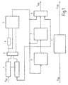
- Fig. 1 shows a block diagram of the arrangement according to the invention, the a doubling of the field frequency of an original image signal allowed and thus generates a converted image signal, this generated image signal is reduced in noise, and that for the partial images line flicker reduction and motion compensation if necessary makes.
- the chroma signal is only doubled in terms of its frequency.
- the special procedure with noise reduction and line flicker reduction is carried out in the example according to FIG. 1 only for the luminance signal. However, it is also possible to take these measures both for the luminance signal and for the chroma signal.
- the luminance signal component Y 50 of the original image signal reaches a first field memory 1, by means of which the field frequency of this signal is doubled.
- Each field of the original image signal read into the field memory 1 is then read out twice. This reading takes place at double frequency. A simple doubling of the field frequency is thus already performed.
- the output signal of this field memory is, however, only suitable for display on a screen when movement disorders and line flicker are accepted.
- a second field memory 2 is also provided, the input side Field signals to be explained are supplied, which are already have twice the field frequency. So stand by Outputs of the two field memories 1 and 2 parallel the signals two successive fields of the original image signal Available, which are already doubled in terms of their field frequency.
- a multiplexer 3 is connected downstream of the two field memories 1 and 2, which alternatively allows one of the output signals of the field memories 1 and 2 to switch to a line memory 4.
- On the Multiplexer 3 receive the output signals of both field memories 1 and 2 to an arrangement 5 for motion compensation.
- Arrangement 5 thus becomes the signals of the two field memories 1 and 2 and thus two successive ones in their field frequency already doubled fields of the original image signal supplied.
- the line memory 4 stands for one of the two field signals at the same time the values of two pixels of the same line position of successive image lines available.
- the arrangement 5 for motion compensation is determined from the two the sub-images fed to it a movement that is contained in the image between these two fields.
- the movement between the two Specifies sub-images for a group of pixels.
- the arrangement 5 for Motion compensation can make this movement both horizontal as well as in the vertical direction, i.e. in the row direction as well as in Determine the direction perpendicular to the lines.
- it can also only the movement in the line direction is determined be that much simpler in circuit design is realized and also delivers good results.
- the arrangement according to FIG. 1 also has an arrangement 6 Noise reduction on.
- This arrangement 6 operates in a manner known per se Way in which they receive the signals from pixels each in the same position successive drawing files combined. These signals are supplied to the arrangement 6 by the arrangement 5. Since the Arrangement 5 has already determined the corresponding motion vector, In arrangement 6, the noise reduction can already be compensated for with motion Signals are made.
- the output signal of the arrangement 6 for noise reduction arrives the input of the second field memory 2, to an input of a Arrangement 7 for line flicker reduction and on a first input of a multiplexer 8.
- the field memory 2 is thus on the input side an already noise-reduced signal is read in, that field corresponds to that from the first field memory 1 to the second Times is read out.
- the arrangement for line flicker reduction 7, for example as Median filter can be designed, which from the supplied to him Signal that with the mean instantaneous amplitude value is selected, in addition to the output signal of the arrangement 6 the output signal of the arrangement 5 for motion compensation supplied, since this output signal also compensates for the movement Output signal of the line memory 4 contains.
- This is required because vertical interpolation is used to reduce line flicker must be made and thus the signals corresponding Pixels, i.e. thus pixels of the same position in their line there must be two lines.
- the arrangement 7 for line flicker reduction receives in addition to this Signals of two successive image lines of a partial image from the Arrangement 6 the signal of another field. In even closer to In an explanatory manner, these signals become median filtering made, which leads to a line flicker reduction.
- the output signal of the arrangement 7 for line flicker reduction is fed to a second input of the multiplexer 8.
- a third entrance of the multiplexer 8 is connected to the output signal of the arrangement 5 Noise reduction applied.
- the multiplexer 8 supplies the luminance signal Y 100 , which represents the converted image signal and that, compared to the input signal Y 50, has a doubled field frequency. Depending on the field to be generated, the multiplexer 8 is switched between its three inputs in a manner still to be explained.
- FIG. 1 also shows a circuit block 9 in which the field frequency of the color signal portion C 50 of the original image signal is doubled. This can be done in the same way as for the luminance signal, but it is also possible to double the field frequency exclusively.
- the unit 9 supplies the color signal portion of the converted image signal on the output side.
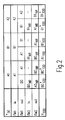
- Fig. 2 shows a table in which is schematically indicated which Fields in the field memories 1 and 2 of the representation according to FIG. 1 be read in or read out from these.
- Two successive fields of the original image signal are in unchanged form e.g. marked as A1, B1 and A2, B2 etc.
- Two drawing files with the same numbering belong to one full picture.
- the two drawing files are interlaced.
- two partial images are, for example A1 and B1 of a frame of the original image signal in the field memory 1, according to FIG. 1, which is designated FM1 in FIG. 2, read.
- Each of these two drawing files is subsequently derived from the Field memory 1 read twice, this reading with twice the frequency, so that the field frequency of these images is already doubled.
- this signal arrives after the arrangement 5 and 1 has passed through the arrangement 6 at the input of the Field memory 2, designated FM2 in the table of FIG. 2 is.
- FM2 the Field memory 2
- FIG. 3 shows a schematic illustration above a broken line of two fields B0 NR and A1 of the original image signal, as are read out of the two field memories 1 and 2 of the representation according to FIG. 1.
- a field A1 100 is shown below the dashed line, which represents the first field of a sequence of the converted image signal. This signal of field A1 100 can be generated by the arrangement according to FIG. 1.
- the output signal of the first field memory 1 is used, from which the field A1 of the original image signal (with a doubled field frequency) is read out.
- Field B0 of the original image signal has already been read into field memory 2, but in a reduced-noise form.
- This signal is now available on the output side at the same time as signal A1 as signal B0 NR at the output of the second field memory.
- the first field A1 100 of the sequence is obtained from these two output signals of the field memories 1 and 2 in accordance with the schematic illustration in FIG. 3.
- This partial image A1 100 to be generated has the correct position vertically and temporally in relation to the partial image A1 of the original image signal. It is therefore only necessary to apply a noise reduction, in particular a line flicker reduction is not necessary.
- the output signals of the field memories 1 and 2 are used for the noise reduction, it being advantageous for the field content of a motion compensation to be used for the field that was read out of the field memory 2 and that does not have the correct temporal position in relation to the field A1 100 to be generated to undergo.
- the motion vector determined by the arrangement 5 for motion compensation according to FIG. 1 is used. This motion vector is designated v x in FIG. 3.
- k is chosen to be small, then little or no noise reduction should be undertaken and this pixel is essentially obtained from the corresponding pixel of sub-picture A1. With a larger factor k, the value of the pixel from field B0 NR is also increasingly used.
- the generated field A1 100 corresponds to the field A1 of the original image signal except for the noise reduction that has been carried out. It is read into the second partial image memory 2 according to FIG. 1 and is available as A1 NR for partial images to be generated subsequently.
- the multiplexer 8 is connected to its first input as shown in FIG. 1, since here the output signals of the noise reduction according to the schematic representation in FIG. 3 are used as the output signal and thus as a signal for the field A1 100 be used.
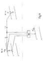
- Fig. 4 shows an illustration corresponding to Figure 3 but for the recovery of the second field B1 -. 100 of the sequence.
- This second field of the sequence has compared to the two fields the correct position of the original image signal neither vertically nor temporally. It therefore becomes a motion compensation and a line flicker reduction performed.
- the first field memory, the field B1 of the original image signal and off the second field memory the field A1 of the original image signal, however, in noise-reduced form, read out.
- an image point of the image line 2 characterized - in the representation of Figure 4 is for the partial image B1.
- the value of this pixel is generated by median filtering from three values, as is obtained from the sub-images A1 NR and B1.
- the first of these values is obtained from the image line 3 for the one pixel of the displaced after application of half the motion vector (v x ⁇ 1 ⁇ 2) the same position is such as to be generated pixel in the partial image B1 - 100.
- the second input of the median filter is calculated from the Pixel of the same line position of line 1 of field A1 NR is obtained. The value of this pixel is also multiplied by a factor k.
- the one pixel of the image line 2 of the field B1 the same after application of the half negative motion vector (v x ⁇ 1 ⁇ 2) image line position has, as to be generated pixel of the partial image B1 - 100, multiplied by a factor 1-k.
- These two values are added and the sum forms the third input signal for median filtering.
- the median filtering is used to select from these three input signals the one that has the mean instantaneous amplitude value. This signal is the value of the designated pixel of the second field B1 - 100 of the sequence.
- the multiplexer 8 is according to the representation of Figure 1 to generate the values of the partial image B1 -. 100 connected to its second input to which the output signal of the arrangement 7 to the line flicker reduction is supplied.
- FIG. 5 also shows a representation corresponding to FIGS. 3 and 4, however, the third field B1 * 100 of the sequence is to be generated in the representation according to FIG. 5.
- the two are used to generate this drawing file corresponding fields A1 and B1 of the original image signal used.
- the drawing file B1 is read out.
- partial image A1 is read out, which is already is reduced in noise.
- a median filtering from three input signals is carried out for the generation of a pixel of the image line 3 of the field B1 * 100 marked in FIG. 5.
- the first of these input signals represents the value of the image point of image line 2 of field B1, which has the same image line position in its image line as the image point to be generated in its image line. Furthermore, from the field A1, as it is read from the second field memory, that pixel is used which, after correction by the movement vector v x, has the same line position as the pixel to be generated. This motion-compensated pixel represents the second input signal of the median filter.
- the third input signal is formed from a sum in which on the one hand the value of the same line position of the pixel of the image line 4 of the field B1, which is multiplied by a factor 1-k, and the value of second input signal of the median filter, which is multiplied by a factor k. This sum represents the third input signal of the median filter and is simultaneously read in as an input signal in the second field memory, from which it can be read out again for field images to be generated subsequently.
- the multiplexer 8 of the block diagram according to FIG. 1 is switched to its second input for the generation of the third field B1 * 100 of the sequence, since a line flicker reduction and also a movement compensation must be carried out.
- FIG. 6 shows a representation corresponding to FIGS. 3 to 5, the values of the fourth field B1 + 100 of the sequence having to be obtained in the representation according to FIG. 6.
- the sub-picture B1 used (in a reduced-noise form) of the original picture signal has the correct position vertically, that is to say has the same position as the picture B1 + 100 , a line flicker reduction is not necessary here.
- the sub-picture B1 NR does not have the correct position in time, so that motion compensation is required.
- the multiplexer 8 Since here only motion compensation (in addition to noise reduction) is required, the multiplexer 8 is on as shown in FIG. 1 switched its third input.
Description
Die Erfindung betrifft eine Anordnung zur Konvertierung eines Original-Bildsignals, das als eine Folge von Vollbildern, von denen sich jedes aus zwei im Zeilensprungverfahren generierten Teilbildern zusammensetzt, in ein konvertiertes Bildsignal, das gegenüber dem Original-Bildsignal eine doppelte Teilbild-Frequenz aufweist.The invention relates to an arrangement for converting an original image signal, that as a sequence of frames, each of which is made up of composes two interlaced fields, in a converted image signal that is one compared to the original image signal has twice the field frequency.
Bei der Konvertierung eines Bildsignals in ein solches konvertiertes Bildsignal, das gegenüber dem ursprünglichen Bildsignal eine doppelte Teilbildfrequenz aufweist, besteht das Problem, daß jedes zweite Teilbild des konvertierten Bildsignals neu erzeugt werden muß, da zeitlich und auch bezüglich der Bildinformation kein entsprechendes Teilbild des Original-Bildsignals zur Verfügung steht.When converting an image signal into one converted Image signal that is double compared to the original image signal Field frequency has the problem that every other field of the converted image signal must be generated again, since temporal and also no corresponding partial image of the image information Original image signal is available.
Bei einfachen Anordnungen zur Verdoppelung der Teilbildfrequenz wird daher jedes zweite Teilbild verdoppelt. Hierbei wird ein bewegtes Objekt in den Teilbildern des konvertierten Bildsignals zweimal in derselben Position abgebildet, bevor es in den beiden darauffolgenden Teilbilder zur nächsten Position springt. Da das menschliche Auge diesen Sprüngen nicht folgen kann, fällt es auf die mittlere Bewegungsgeschwindigkeit ein und nimmt ein bewegtes Objekt von Teilbild zu Teilbild an jeweils verschiedenen Positionen wahr. Dadurch entsteht eine Doppelstruktur und Bewegungsunschärfe.With simple arrangements for doubling the field frequency therefore every second field is doubled. This is a moving object twice in the fields of the converted image signal Position mapped before it in the two subsequent drawing files jumps to the next position. Because the human eye this If jumps cannot follow, it falls on the average movement speed and increases a moving object from drawing file Drawing file true in different positions. This creates one Double structure and motion blur.
Daher ist bei anderen Anordnungen zur Teilbildverdoppelung eines Bildsignals eine Bewegungskompensation vorgesehen, mittels welcher die Bewegung zwischen zwei Teilbildern des Original-Bildsignals ermittelt wird, so daß in zeitlich dazwischen zu generierenden Teilbildern des konvertierten Bildsignals die Bewegung berücksichtigt werden kann und eine entsprechende Interpolation vorgenommen werden kann. Bei derartigen Anordnungen besteht jedoch weiterhin das Problem, daß zusätzlich ein gegebenenfalls vorhandenes Rauschen reduziert werden soll und daß das trotz der Verdoppelung der Teilbild-Frequenz bei Bildsignalen, die im Zeilensprungverfahren generiert sind, das immer noch auftretende Zeilenflimmern reduziert werden soll. Nach dem Stande der Technik sind nur Anordnungen bekannt, bei denen eine Bewegungskompensation entweder mit einer Rauschreduktion oder mit einer Zeilenflimmer-reduktion kombiniert ist.Therefore, in other arrangements for field doubling one Motion signal compensation provided by means of which the movement between two fields of the original image signal is determined is, so that in the intermediate images to be generated between the converted image signal the movement can be taken into account and a corresponding interpolation can be carried out. With such Arrangements, however, still have the problem of being additional any existing noise should be reduced and that despite the doubling of the field frequency for image signals, that are interlaced, the still occurring Line flicker should be reduced. According to the state of the art only known arrangements in which motion compensation either with a noise reduction or with a line flicker reduction is combined.
Es ist Aufgabe der Erfindung, eine Anordnung zu schaffen, welche bei der Konvertierung des Bildsignals in ein konvertiertes Bildsignal mit doppelter Teilbildfrequenz die Bewegung des Bildinhaltes bei der Generierung der kompensierten Teilbilder berücksichtigt wird und welche außerdem eine Rauschreduktion des Bildsignals und eine Zeilenflimmer-reduktion gestattet.It is an object of the invention to provide an arrangement which the conversion of the image signal into a converted image signal with double field frequency the movement of the image content at Generation of the compensated drawing files is taken into account and which also a noise reduction of the image signal and a line flicker reduction allowed.
Diese Aufgabe ist erfindungsgemäß dadurch gelöst, daß zur Verdoppelung der Teilbild-Frequenz eine Speicher-Anordnung vorgesehen ist, der eine Anordnung zur Bewegungskompensation nachgeschaltet ist, deren Ausgangssignal auf eine Anordnung zur Rauschreduktion geschaltet ist, daß eine Anordnung zur Zeilenflimmerreduktion vorgesehen ist, der die Ausgangssignale der Anordnung zur Rauschreduktion und der Anordnung zur Bewegungskompensation zugeführt werden, und daß das konvertierte Bildsignal in Abhängigkeit der zeitlichen Lage eines zu generierenden Teilbildes des konvertierten Bildsignals aus dem Ausgangssignal der Anordnung zur Rauschreduktion, der Anordnung zur Zeilenflimmerreduktion oder der Anordnung zur Bewegungskompensation gewonnen wird.This object is achieved in that for doubling the field frequency a storage arrangement is provided is followed by an arrangement for motion compensation, whose output signal to an arrangement for noise reduction is switched that an arrangement for line flicker reduction is provided which is the output signals of the arrangement for noise reduction and the arrangement for motion compensation are supplied, and that the converted image signal depending on the temporal position of a field to be generated of the converted image signal from the output signal the arrangement for noise reduction, the arrangement for Line flicker reduction or the arrangement for motion compensation is won.
Die reine Verdoppelung der Teilbild-Frequenz wird mittels einer Speicher-anordnung vorgenommen. Dadurch werden die Teilbilder des Original-Bildsignals in doppelter Frequenz wiederholt, so daß eine doppelte Teilbild-Frequenz entsteht. Dieses Signal weist jedoch noch die oben erläuterten Fehler auf.The pure doubling of the field frequency is achieved by means of a memory arrangement performed. As a result, the partial images of the original image signal repeated in double frequency so that a double Field frequency arises. However, this signal still shows the one above explained errors.
Daher ist eine Anordnung zur Bewegungskompensation vorgesehen, welche Bewegungen im Orignal-Bildsignal ermittelt und anhand der bekannten Bewegungen eine Kompensation dieser Bewegung in den neu zu generierenden Teilbildern des kompensierten Signals erlaubt.An arrangement for motion compensation is therefore provided, which movements in the original image signal are determined and based on the known movements a compensation of this movement in the new allowed to generate partial images of the compensated signal.
Der Anordnung zur Bewegungskompensation ist eine Anordnung zur Rauschreduktion nach geschaltet, welche in an sich bekannter Weise zur Rauschreduktion die Daten zweier aufeinanderfolgender Teilbilder miteinander verknüpft.The arrangement for motion compensation is an arrangement for Noise reduction switched after, which in a manner known per se Noise reduction the data of two successive fields with each other connected.
Ferner ist eine Anordnung zur Zeilenflimmerreduktion vorgesehen, der die Ausgangssignale der Anordnung zur Bewegungskompensation und die Ausgangssignale der Anordnung zur Rauschreduktion zugeführt werden.Furthermore, an arrangement for line flicker reduction is provided, which the output signals of the arrangement for motion compensation and the output signals of the arrangement for noise reduction fed will.
Das Ausgangssignal der Anordnung, also das konvertierte Bildsignal mit der doppelten Teilbild-Frequenz, wird in Abhängigkeit der zeitlichen Lage eines zu generierenden Teilbildes des konvertierten Bildsignals aus dem Ausgangssignal einer der drei genannten Anordnungen gewonnen. Dieser Wechsel zwischen den Ausgangssignalen der Anordnungen ist vorteilhaft, da je nach zeitlicher Lage der Teilbilder des konvertierten Bildsignals verschiedene Fehler auftreten. Bei einigen Teilbildern ist eine Bewegungskompensation erforderlich, da sie zeitlich zwischen zwei Teilbildern des Original-Bildsignals fallen. Bei solchen Teilbildern, die zeitlich mit Bildern des Original-Bildsignals zusammenfallen, ist dies nicht erforderlich. Die Zeilenflimmerreduktion wiederum ist nur bei solchen Teilbildern erforderlich, die infolge des Zeilensprung-Verfahrens nicht die richtige vertikale Position haben, verglichen mit den Teilbildern des Original-Bildsignals, aus denen sie generiert werden.The output signal of the arrangement, i.e. the converted image signal with the double field frequency, is dependent on the temporal position a field of the converted image signal to be generated from the Output signal obtained from one of the three arrangements mentioned. This change is between the output signals of the arrays advantageous because, depending on the temporal position of the partial images of the converted Image signal various errors occur. For some drawing files there is one Motion compensation is required because it is between two Fields of the original image signal fall. In such sub-images that this does not coincide with images of the original image signal required. The line flicker reduction in turn is only for such Fields required because of the interlace method not the have the correct vertical position compared to the partial images of the Original image signal from which they are generated.
Die erfindungsgemäße Anordnung bietet also eine Kombination der Bewegungskonvensation mit der Zeilenflimmerreduktion und der Rauschreduktion.The arrangement according to the invention thus offers a combination of Motion convection with line flicker reduction and Noise reduction.
Eine Ausgestaltung für die Anordnung sieht vor, daß das Original-Bildsignal in einen ersten Teilbildspeicher eingelesen wird, aus dem es mit doppelter Frequenz ausgelesen wird, wobei jedes Teilbild zweimal hintereinander ausgelesen wird, und daß ein zweiter Teilbildspeicher vorgesehen ist, in den jedes aus dem ersten Teilbildspeicher zum zweiten Mal ausgelesene Teilbild nach Durchlaufen der Anordnung zur Rauschreduktion eingelesen wird.A configuration for the arrangement provides that the original image signal is read into a first field memory, from which it is double frequency is read, each field twice is read out in succession, and that a second field memory is provided, in which each from the first field memory for field read out a second time after running through the arrangement for Noise reduction is read in.
Der erste Teilbildspeicher dient also zur Verdoppelung der Teilbildfrequenz. Jedes in diesen Speicher eingelesene Teilbild wird zweimal hintereinander ausgelesen. Ein zweiter Teilbildspeicher arbeitet bereits eingangsseitig mit dieser doppelten Teilbild-Frequenz, da in diesen jedes Teilbild, das aus dem ersten Teilbildspeicher zum zweiten Mal ausgelesen wurde und daß die Anordnung zur Rauschreduktion durchlaufen hat, eingelesen wird. Nach dem Einlesen steht dieses rauschreduzierte Teilbild ausgangsseitig am zweiten Teilbildspeicher zur Verfügung.The first field memory is used to double the field frequency. Each field read into this memory becomes twice read out in succession. A second field memory is already working on the input side with this double field frequency, since in each of these Field that is read out from the first field memory for the second time and that the arrangement for noise reduction has gone through has, is read. After reading, this is reduced noise Drawing file available on the output side at the second drawing file memory.
Damit stehen zur Bewegungskompensation an den Ausgängen der beiden Teilbildspeicher zwei Teilbilder des Original-Bildsignals, jedoch mit verdoppelter Teilbild-Frequenz, zur Verfügung. Eines dieser Teilbilder ist bereits rauschreduziert, was der Anordnung zur Bewegungskompensation die Ermittlung der Bewegung vereinfacht.So there are motion compensation at the Outputs of the two field memories two fields of the original image signal, however with a doubled field frequency. One this drawing file is already reduced in noise, which makes the arrangement for Motion compensation simplifies the determination of the motion.
Wie nach einer weiteren Ausgestaltung der Erfindung vorgesehen ist, kann den beiden Teilbildspeichern ein Zeilenspeicher nachgeschaltet sein, welcher eine Bildzeile eines der Ausgangssignale der beiden Teilbilder zwischenspeichert. Damit ist für eines der Teilbilder zeitlich parallel eine Information zweier aufeinanderfolgender Bildzeilen vorhanden, was für die nachgeschaltete Zeilenflimmer-Reduktion von Vorteil ist.As is provided according to a further embodiment of the invention, a line memory can follow the two field memories be, which is a picture line of one of the output signals of the two fields cached. This means that one of the drawing files is parallel in time information of two successive picture lines is available, what is advantageous for the subsequent line flicker reduction.
Die Anordnung zur Zeilenflimmer-Reduktion kann, wie nach einer weiteren Ausgestaltung der Erfindung vorgesehen ist, vorteilhalft als Medianfilter ausgelegt sein, welches ausgangsseitig dasjenige Eingangssignal zur Verfügung stellt, das den mittleren Amplitudenwert der Eingangssignale aufweist.The arrangement for line flicker reduction can, as after a Another embodiment of the invention is provided, advantageously as Median filter be designed, which on the output side that input signal which provides the mean amplitude value of the Has input signals.
Gemäß einer weiteren Ausgestaltung der Erfindung ist vorgesehen, daß der Anordnung zur Bewegungskompensation die Ausgangssignale der beiden Teilbildspeicher und des Zeilenspeichers zugeführt werden, und daß die Anordnung zur Bewegungskompensation aus den beiden aus den Teilbildspeichern ausgelesenen, aufeinanderfolgenden Teilbildern des Original-Bildsignals einen Bewegungsvektor ermittelt, der für eine Gruppe von Bildpunkten dieser Teilbilder deren Bewegung zwischen den beiden Teilbildern angibt.According to a further embodiment of the invention it is provided that the arrangement for motion compensation, the output signals of both field memory and the line memory are supplied, and that the arrangement for motion compensation from the two the successive fields of the field memories read out Original image signal determines a motion vector for a group of pixels of these partial images, their movement between the two Indicates drawing files.
Dieser Bewegungsvektor kann dazu eingesetzt werden, in denjenigen Teilbildern des konvertierten Teilbildsignals eine Bewegungskompensation vorzunehmen, die zeitlich zwischen zwei Teilbilder des Original-Bildsignals fallen.This motion vector can be used in those Fields of the converted field signal a motion compensation make the time between two fields of the original image signal fall.
Eine weitere Ausgestaltung der Erfindung sieht für die Anordnung vor, daß diese zu zwei Teilbildern eines Vollbildes des Original-Bildsignals, eine korrespondierende Sequenz von vier Teilbildern (A1100, B- 100, B1*100, B1+ 100) des konvertierten Bildsignals generiert, wobei das erste Teilbild (A1100) der Sequenz aus dem Ausgangssignal der Anordnung zur Rauschreduktion, das zweite und dritte Teilbild (B1- 100, B1*100) der Sequenz aus dem Ausgangssignal zur Zeilenflimmerreduktion und das vierte Teilbild (B1+ 100) der Sequenz aus der Anordnung zur Bewegungskompensation gewonnen wird.A further embodiment of the invention provides that the arrangement generates a corresponding sequence of four fields (A1 100 , B - 100 , B1 * 100 , B1 + 100 ) of the converted image signal for two fields of a frame of the original image signal, wherein the first field (A1 100 ) of the sequence from the output signal of the arrangement for noise reduction, the second and third field (B1 - 100 , B1 * 100 ) of the sequence from the output signal for line flicker reduction and the fourth field (B1 + 100 ) of the sequence is obtained from the arrangement for motion compensation.
Infolge der verdoppelten Teilbild-Frequenz des konvertierten Bildsignals müssen in einem zeitlichen Bereich, in dem zwei Teilbilder des Original-Bildsignals vorliegen, vier Teilbilder des konvertierten Bildsignals erzeugt werden. Im folgenden werden diese zwei Teilbilder des Original-Bildsignals und die vier Teilbilder der entsprechenden Sequenz des konvertierten Bildsignals als korrespondierende Teilbilder bzw. korrespondierende Sequenz bezeichnet.As a result of the doubled field frequency of the converted image signal must be in a time range in which two fields of the original image signal are present, four fields of the converted image signal are generated will. The following are these two fields of the original image signal and the four fields of the corresponding sequence of the converted image signal as corresponding partial images or corresponding sequence called.
Das erste Teilbild der Sequenz wird aus dem Ausgangssignal der Anordnung zur Rauschreduktion gewonnen. Dies ist möglich, da dieses erste Teilbild der Sequenz gegenüber dem ersten korrespondierenden Teilbild des Original-Bildsignals zeitlich und örtlich die richtige Lage hat und lediglich eine Rauschreduktion vorgenommen werden muß. The first field of the sequence is derived from the output signal of the Noise reduction arrangement won. This is possible because of this first partial image of the sequence compared to the first corresponding one The partial image of the original image signal has the correct position in terms of time and location and only a noise reduction needs to be made.
Das zweite und dritte Teilbild der Sequenz wird aus dem Ausgangssignal zur Zeilenflimmerreduktion gewonnen, da für diese beiden Teilbilder beide Teilbilder des Original-Bildsignals herangezogen werden müssen, von denen zumindest jeweils eines nicht die richtige zeitliche Lage hat und infolge des angewandten Zeilensprungverfahrens auch nicht die richtige vertikale Position hat.The second and third fields of the sequence are derived from the output signal obtained for line flicker reduction, since for these two partial images both partial images of the original image signal must be used, at least one of which does not have the correct timing and not due to the interlaced method used has the correct vertical position.
Das Signal für das vierte Teilbild der Sequenz wird aus der Anordnung zur Bewegungskompensation gewonnen, da dieses Signal nur durch Anwendung der Bewegungskompensation aus dem zweiten korrespondierenden Teilbild des Original-Bildsignals gewonnen werden kann.The signal for the fourth field of the sequence is made up of the arrangement obtained for motion compensation, since this signal can only be obtained by Application of motion compensation from the second corresponding Field of the original image signal can be obtained.
In den weiteren Unteransprüchen ist angegeben, wie die Anordnung vorteilhafterweise die vier Teilbilder zur Sequenz des konvertierten Bildsignals aus dem korrespondierenden beiden Teilbildes des Original-Bildsignals generiert.The other subclaims state how the arrangement advantageously the four fields for the sequence of the converted image signal from the corresponding two fields of the original image signal generated.
Ein Ausführungsbeispiel der Erfindung wird nachfolgend anhand der
Zeichnung näher erläutert. Es zeigen:
Fig. 1 zeigt ein Blockschaltbild der erfindungsgemäßen Anordnung, die eine Verdoppelung der Teilbild-Frequenz eines Original-Bildsignals gestattet und so ein konvertiertes Bildsignal generiert, wobei dieses generierte Bildsignal rauschreduziert ist, und die für die Teilbilder erfordlichenfalls eine Zeilenflimmerreduktion und eine Bewegungskompensation vornimmt.Fig. 1 shows a block diagram of the arrangement according to the invention, the a doubling of the field frequency of an original image signal allowed and thus generates a converted image signal, this generated image signal is reduced in noise, and that for the partial images line flicker reduction and motion compensation if necessary makes.
Die Anordnung gemäß Fig. 1 gliedert sich in zwei Blöcke, von denen der erste Block das ihm zugeführte Luminanzsignal Y50 des Original-Bildsignals bearbeitet und der zweite Block das ihm zugeführte Chromasignal C50 des Original-Bildsignals. In dem in der Fig. 1 dargestellten Beispiel wird das Chromasignal lediglich bezüglich seiner Frequenz verdoppelt. Die besondere Vorgehensweise mit Rauschreduktion und Zeilenflimmerreduktion wird in dem Beispiel gemäß Fig. 1 nur für das Luminanzsignal vorgenommen. Es ist jedoch auch möglich, diese Maßnahmen sowohl für das Luminanzsignal wie auch für das Chromasignal vorzunehmen.1 is divided into two blocks, of which the first block processes the luminance signal Y 50 of the original image signal supplied to it and the second block processes the chroma signal C 50 of the original image signal supplied to it. In the example shown in FIG. 1, the chroma signal is only doubled in terms of its frequency. The special procedure with noise reduction and line flicker reduction is carried out in the example according to FIG. 1 only for the luminance signal. However, it is also possible to take these measures both for the luminance signal and for the chroma signal.
Der Luminanzsignalanteil Y50 des Original-Bildsignals gelangt in der
Anordnung gemäß Fig. 1 auf einen ersten Teilbildspeicher 1, mittels
welchem die Teilbild-Frequenz dieses Signals verdoppelt wird. Jedes in
den Teilbildspeicher 1 eingelesene Teilbild des Original-Bildsignals wird
anschließend zweimal ausgelesen. Dieses Auslesen geschieht mit
doppelter Frequenz. Damit wird bereits eine einfache Verdoppelung der
Teilbild-Frequenz vorgenommen. Das Ausgangssignal dieses Teilbildspeichers
ist jedoch zur Darstellung auf einem Bildschirm nur unter
Inkaufnahme von Bewegungsstörungen und Zeilenflimmern geeignet. In the arrangement according to FIG. 1, the luminance signal component Y 50 of the original image signal reaches a
Es ist ferner ein zweiter Teilbildspeicher 2 vorgesehen, dem eingangsseitig
noch zu erläuternde Teilbild-Signale zugeführt werden, die bereits
die doppelte Teilbild-Frequenz aufweisen. Damit stehen an den
Ausgängen der beiden Teilbildspeicher 1 und 2 parallel die Signale
zweier aufeinanderfolgender Teilbilder des Original-Bildsignals zur
Verfügung, die bezüglich ihrer Teilbild-Frequenz bereits verdoppelt sind.A
Den beiden Teilbildspeichern 1 und 2 ist ein Multiplexer 3 nachgeschaltet,
der es gestattet, alternativ eines der Ausgangssignale der Teilbildspeicher
1 und 2 auf einen Zeilenspeicher 4 zu schalten. Über den
Multiplexer 3 gelangen die Ausgangssignale beider Teilbildspeicher 1
und 2 an eine Anordnung 5 zur Bewegungskompensation. Der
Anordnung 5 werden also die Signale der beiden Teilbildspeicher 1
und 2 und damit zweier aufeinanderfolgender, in ihrer Teilbildfrequenz
bereits verdoppelter Teilbilder des Original-Bildsignals zugeführt. Durch
den Einsatz des Zeilenspeichers 4 stehen für eines der beiden Teilbildsignale
gleichzeitig die Werte zweier Bildpunkte gleicher Zeilenposition
von aufeinanderfolgenden Bildzeilen zur Verfügung.A
Die Anordnung 5 zur Bewegungskompensation ermittelt aus den beiden
ihr zugeführten Teilbildern eine Bewegung, die in den Bildinhalten
zwischen diesen beiden Teilbildern vorliegt. Vorteilhafterweise wird für
eine Gruppe von Bildpunkten aus dieser ermittelten Bewegung ein
Bewegungsvektor gewonnen, der die Bewegung zwischen den beiden
Teilbildern für eine Gruppe von Bildpunkten angibt. Die Anordnung 5 zur
Bewegungskompensation kann diese Bewegung sowohl in horizontaler
wie auch in vertikaler Richtung, d.h. also in Zeilenrichtung wie auch in
Richtung senkrecht zu den Zeilen ermitteln. Es kann jedoch auch
ausschließlich eine Ermittlung der Bewegung in Zeilenrichtung vorgenommen
werden, die im Schaltungsaufbau sehr viel einfacher zu
realisieren ist und auch gute Ergebnisse liefert.The
Die Anordnung gemäß Fig. 1 weist ferner eine Anordnung 6 zur
Rauschreduktion auf. Diese Anordnung 6 arbeitet in an sich bekannter
Weise, in dem sie die Signale von Bildpunkten jeweils gleicher Lage
aufeinanderfolgender Teilbilder miteinander kombiniert. Diese Signale
werden der Anordnung 6 von der Anordnung 5 zugeführt. Da die
Anordnung 5 bereits den entsprechenden Bewegungsvektor ermittelt hat,
kann in der Anordnung 6 die Rauschreduktion bereits mit bewegungskompensierten
Signalen vorgenommen werden.The arrangement according to FIG. 1 also has an
Das Ausgangssignal der Anordnung 6 zur Rauschreduktion gelangt auf
den Eingang des zweiten Teilbildspeichers 2, auf einen Eingang einer
Anordnung 7 zur Zeilenflimmerreduktion und auf einen ersten Eingang
eines Multiplexers 8. In den Teilbildspeicher 2 wird damit eingangsseitig
ein bereits rauschreduziertes Signal eingelesen, das demjenigen Teilbild
entspricht, das aus dem ersten Teilbildspeicher 1 bereits zum zweiten
Mal ausgelesen wird.The output signal of the
Der Anordnung zur Zeilenflimmer-Reduktion 7, die beispielsweise als
Medianfilter ausgelegt sein kann, welches aus dem ihm zugeführten
Signal jeweils dasjenige mit dem mittleren Amplituden-Momentanwert
auswählt, wird außer dem Ausgangssignal der Anordnung 6 auch noch
das Ausgangssignal der Anordnung 5 zur Bewegungskompensation
zugeführt, da dieses Ausgangssignal auch dasjenige bewegungskompensierte
Ausgangssignal des Zeilenspeichers 4 enthält. Dieses ist
erforderlich, da für die Zeilenflimmer-Reduktion eine vertikale Interpolation
vorgenommen werden muß und somit die Signale korrespondierender
Bildpunkte, d.h. also Bildpunkte gleicher Lage in ihrer Zeile, aus
zwei Zeilen vorliegen müssen.The arrangement for
Die Anordnung 7 zur Zeilenflimmer-Reduktion erhält außer diesen
Signalen zweier aufeinanderfolgender Bildzeilen eines Teilbildes aus der
Anordnung 6 das Signal eines anderen Teilbildes. In noch näher zu
erläuterender Weise wird aus diesen Signalen eine Medianfilterung
vorgenommen, die zu einer Zeilenflimmer-Reduktion führt.The
Das Ausgangssignal der Anordnung 7 zur Zeilenflimmer-Reduktion wird
einem zweiten Eingang des Multiplexers 8 zugeführt. Ein dritter Eingang
des Multiplexers 8 ist mit dem Ausgangssignal der Anordnung 5 zur
Rauschreduktion beaufschlagt.The output signal of the
Der Multiplexer 8 liefert ausgangsseitig das Luminanzsignal Y100, das das
konvertierte Bildsignal darstellt und daß gegenüber dem Eingangssignal
Y50 eine verdoppelte Teilbild-Frequenz aufweist. Der Multiplexer 8
wird je nach zu generierenden Teilbild in noch zu erläuternder Weise
zwischen seinen drei Eingängen umgeschaltet.On the output side, the
Die Fig. 1 zeigt ferner einen Schaltungsblock 9, in dem eine Verdoppelung
der Teilbild-Frequenz des Farbsignal-Anteils C50 des Original-Bildsignals
vorgenommen wird. Dies kann in gleicher Weise geschehen
wie für das Luminanzsignal, es kann jedoch auch ausschließlich einer
Verdoppelung der Teilbild-Frequenz vorgenommen werden. Die Einheit 9
liefert ausgangsseitig den Farbsignalanteil des konvertierten Bildsignals.1 also shows a
Fig. 2 zeigt eine Tabelle, in der schematisch angedeutet ist, welche
Teilbilder in die Teilbildspeicher 1 und 2 der Darstellung gemäß Fig. 1
eingelesen werden bzw. aus diesen ausgelesen werden.Fig. 2 shows a table in which is schematically indicated which
Fields in the
Zwei aufeinanderfolgende Teilbilder des Original-Bildsignals sind in unveränderter Form z.B. als A1, B1 und A2, B2 etc. gekennzeichnet. Zwei Teilbilder mit gleicher Bezifferung gehören dabei zu einem Vollbild. Die beiden Teilbilder sind im Zeilensprungverfahren generiert.Two successive fields of the original image signal are in unchanged form e.g. marked as A1, B1 and A2, B2 etc. Two drawing files with the same numbering belong to one full picture. The two drawing files are interlaced.
Wie die Tabelle gemäß Fig. 2 zeigt, werden beispielsweise zwei Teilbilder
A1 und B1 eines Vollbildes des Original-Bildsignals in den Teilbilderspeicher
1, gemäß Fig. 1, der in Fig. 2 mit FM1 bezeichnet ist,
eingelesen. Jedes dieser beiden Teilbilder wird nachfolgend aus dem
Teilbildspeicher 1 zweimal ausgelesen, wobei dieses Auslesen mit
doppelter Frequenz erfolgt, so daß die Teilbild-Frequenz dieser Bilder
bereits verdoppelt ist.As the table in FIG. 2 shows, two partial images are, for example
A1 and B1 of a frame of the original image signal in the
Wird ein Teilbild zum zweiten Mal aus dem ersten Teilbildspeicher 1
ausgelesen, so gelangt dieses Signal, nachdem es die Anordnung 5 und
die Anordnung 6 gemäß Fig. 1 durchlaufen hat, an den Eingang des
Teilbildspeichers 2, der in der Tabelle gemäß Fig. 2 mit FM2 bezeichnet
ist. Beim nächsten Auslesevorgang der Teilbilderspeicher 1 und 2 stehen
dabei an deren Ausgängen jeweils zwei Teilbilder zur Verfügung, die in
ihrer Teilbild-Frequenz bereits verdoppelt sind. Da eines der Teilbilder,
nämlich dasjenige, das in den Teilbilderspeicher 2 eingelesen wurde,
bereits die Rauschreduktion durchlaufen hat, ist dieses bereits rauschreduziert,
was in der Darstellung der Tabelle gemäß Fig. 2 mit den
Indices NR gekennzeichnet ist.If a partial image is extracted from the first
Im Ergebnis stehen an den Ausgängen der Teilbildspeicher 1 und 2 der
Darstellung gemäß Fig. 1 zwei Teilbilder zur Verfügung, die aus dem
Original-Bildsignal hervorgehen, die jedoch bereits verdoppelte Teilbild-Frequenz
aufweisen.The result is at the outputs of
Im folgenden soll anhand der Fig. 3 bis 6 näher erläutert werden, wie
die vier Teilbilder A1100, B1-100, B1*100 und B1+100des Ausgangssignals
Y100 entsprechend der Tabelle gemäß Fig. 2, die die Ausgangssignale
des Multiplexers 8 der Darstellung gemäß Fig. 1 sind, gewonnen
werden. Diese vier Teilbilder werden im folgenden als zu einer Sequenz
zugehörig bezeichnet. Zu dieser Sequenz korrespondiert ein Vollbild des
Original-Bildsignals, bzw. zwei Teilbilder dieses Signals, nämlich die
Teilbilder A1 und B1. Im folgenden werden die vier Teilbilder der
Sequenz als korrespondierend mit diesen vier Teilbildern des Original-Bildsignals
bezeichnet., B1 * 100, and B1 + 100des output signal Y, 100 100 corresponding to the table of Figure 2 that of the output signals of the
Fig. 3 zeigt in einer schematischen Darstellung oberhalb einer
gestrichelten Linie zwei Teilbilder B0NR und A1 des Original-Bildsignals,
wie sie aus den beiden Teilbildspeichern 1 und 2 der Darstellung gemäß
Fig. 1 ausgelesen werden. Unterhalb der gestrichelten Linie ist ein Teilbild
A1100 dargestellt, das das erste Teilbild einer Sequenz des
konvertierten Bildsignals darstellt. Dieses Signal des Teilbildes A1100 ist
durch die Anordnung gemäß Fig. 1 zu erzeugen. FIG. 3 shows a schematic illustration above a broken line of two fields B0 NR and A1 of the original image signal, as are read out of the two
Dazu wird einerseits das Ausgangssignal des ersten Teilbildspeichers 1
herangezogen, aus dem das Teilbild A1 des Original-Bildsignals (mit
verdoppelter Teilbild-Frequenz) ausgelesen wird. In den Teilbildspeicher
2 wurde zuvor bereits das Teilbild B0 des Original-Bildsignals,
jedoch in rauschreduzierter Form, eingelesen. Dieses Signal steht nun
ausgangsseitig gleichzeitig mit dem Signal A1 als Signal B0NR am
Ausgang des zweiten Teilbildspeichers zur Verfügung. Aus diesen beiden
Ausgangssignalen der Teilbildspeicher 1 und 2 wird entsprechend der
schematischen Darstellung in Fig. 3 das erste Teilbild A1100 der Sequenz
gewonnen.For this purpose, on the one hand, the output signal of the
Dieses zu generierende Teilbild A1100 hat gegenüber dem Teilbild A1 des Original-Bildsignals vertikal und zeitlich die richtige Position. Es muß daher nur eine Rauschreduktion zugeführt werden, insbesondere ist eine Zeilenflimmer-Reduktion nicht erforderlich.This partial image A1 100 to be generated has the correct position vertically and temporally in relation to the partial image A1 of the original image signal. It is therefore only necessary to apply a noise reduction, in particular a line flicker reduction is not necessary.
Für die Rauschreduktion werden die Ausgangssignale der Teilbildspeicher
1 und 2 herangezogen, wobei es vorteilhaft ist, das Teilbild,
das aus dem Teilbildspeicher 2 ausgelesen wurde, und das gegenüber
dem zu generierenden Teilbild A1100 nicht die richtige zeitliche Position
hat, in seinem Bildinhalt einer Bewegungskompensation zu unterziehen.
Dazu wird der von der Anordnung 5 zur Bewegungskompensation entsprechend
der Fig. 1 ermittelte Bewegungsvektor herangezogen. Dieser
Bewegungsvektor ist in der Fig. 3 mit vx bezeichnet.The output signals of the
Für einen in der Fig. 3 in dem Teilbild A1100 in dessen Bildzeile 3
gekennzeichneten Bildpunkt wird nun einerseits der Bildpunkt gleicher
Zeilenposition und gleicher Zeilenzahl aus dem Teilbild A1100, wie aus
dem Teilbildspeicher 1 ausgelesen wird, herangezogen. Ferner wird der
um den Bewegungsvektor vx verschobene Bildpunkt des Teilbildes B0NR,
wie es aus dem zweiten Teilbildspeicher ausgelesen wird, verwendet.
Dieser Bildpunkt wird der Zeile 4 entnommen. Aus diesen beiden Bildpunkten
der beiden Teilbilder wird ein rauschreduziertes Signal
gewonnen. Dafür ist ein Faktor k vorgesehen, der angibt, wie stark die
Rauschreduktion erfolgen soll. Der Bildpunkt aus dem Teilbild A1 wird
mit einem Faktor 1-k und der Bildpunkt aus dem Teilbild B0NR mit einem
Faktor k multipliziert. Diese beiden multiplizierten Werte werden addiert
und bilden den Wert des gekennzeichneten Bildpunktes des Teilbildes
A1100.For a pixel identified in FIG. 3 in partial image A1 100 in its
Wird k klein gewählt, so soll nur eine geringe oder gar keine Rauschreduktion vorgenommen werden und dieser Bildpunkt wird im wesentlichen aus dem korrespondierenden Bildpunkt des Teilbildes A1 gewonnen. Mit größerem Faktor k wird zunehmend auch der Wert des Bildpunktes aus dem Teilbild B0NR herangezogen.If k is chosen to be small, then little or no noise reduction should be undertaken and this pixel is essentially obtained from the corresponding pixel of sub-picture A1. With a larger factor k, the value of the pixel from field B0 NR is also increasingly used.
Das generierte Teilbild A1100 entspricht also bis auf die vorgenommene
Rauschreduktion dem Teilbild A1 des Original-Bildsignals. ES wird in den
zweiten Teilbildspeicher 2 gemäß Fig. 1 eingelesen und steht für nachfolgend
zu generierende Teilbilder in diesem als A1NR zur Verfügung.The generated field A1 100 corresponds to the field A1 of the original image signal except for the noise reduction that has been carried out. It is read into the second
Während der Generierung des ersten Teilbildes A1100 ist der Multiplexer 8
entsprechend der Darstellung gemäß Fig. 1 auf seinen ersten Eingang
geschaltet, da hier die Ausgangssignale der Rauschreduktion entsprechend
der schematischen Darstellung in Fig. 3 als Ausgangssignal
und damit als Signal für das Teilbild A1100 herangezogen werden.During the generation of the first field A1 100 , the
Fig. 4 zeigt eine Darstellung entsprechend Fig. 3, jedoch für die Gewinnung des zweiten Teilbildes B1- 100 der Sequenz.Fig. 4 shows an illustration corresponding to Figure 3 but for the recovery of the second field B1 -. 100 of the sequence.
Dieses zweite Teilbild der Sequenz hat gegenüber den beiden Teilbildern des Original-Bildsignals weder vertikal noch zeitlich die richtige Position. Es wird daher eine Bewegungskompensation und eine Zeilenflimmer-Reduktion vorgenommen.This second field of the sequence has compared to the two fields the correct position of the original image signal neither vertically nor temporally. It therefore becomes a motion compensation and a line flicker reduction performed.
Zum Zeitpunkt der Generierung dieses zweiten Teilbildes wird aus dem ersten Teilbildspeicher das Teilbild B1 des Original-Bildsignals und aus dem zweiten Teilbildspeicher das Teilbild A1 des Original-Bildsignals, jedoch in rauschreduzierter Form, ausgelesen. At the time of generation of this second drawing file, the first field memory, the field B1 of the original image signal and off the second field memory the field A1 of the original image signal, however, in noise-reduced form, read out.
In der Darstellung gemäß Fig. 4 ist für das Teilbild B1- 100 ein Bildpunkt
der Bildzeile 2 gekennzeichnet. Der Wert dieses Bildpunktes wird durch
Medianfilterung aus drei Werten generiert, wie aus den Teilbildern A1NR
und B1 gewonnen werden.. 100 an image point of the
Der erste dieser Werte wird aus der Bildzeile 3 für denjenigen Bildpunkt
gewonnen, der nach Anwendung des halben Bewegungsvektors (vx · ½)
verschoben die gleiche Position hat wie der zu generierende Bildpunkt
im Teilbild B1-100. Das zweite Eingangssignal des Medianfilters wird aus
dem Bildpunkt gleicher Zeilenposition der Zeile 1 des Teilbildes A1NR
gewonnen. Der Wert dieses Bildpunktes wird außerdem mit einem
Faktor k multipliziert. Ferner wird derjenige Bildpunkt aus der Bildzeile 2
des Teilbildes B1, der nach Anwendung des halben negativen
Bewegungsvektors (-vx · ½) gleiche Bildzeilenposition hat, wie der zu
generierende Bildpunkt des Teilbildes B1- 100, mit einem Faktor 1-k multipliziert.
Diese beiden Werte werden addiert und die Summe bildet das
dritte Eingangssignal für die Medianfilterung. Durch die Medianfilterung
wird aus diesen drei Eingangssignalen dasjenige ausgewählt, das den
mittleren Momentan-Amplitudenwert aufweist. Dieses Signal ist der Wert
des gekennzeichneten Bildpunktes des zweiten Teilbildes B1- 100 der
Sequenz.The first of these values is obtained from the
Wie schon die Darstellung gemäß Fig. 4 zeigt, ist für dieses Teilbild eine
Bewegungskompensation für alle Signale erforderlich. Ferner muß eine
Zeilenflimmer-Reduktion vorgenommen werden. Daher wird der Multiplexer
8 entsprechend der Darstellung gemäß Fig. 1 für die Generierung
der Werte des Teilbildes B1- 100 auf seinen zweiten Eingang geschaltet,
dem das Ausgangssignal der Anordnung 7 zur Zeilenflimmer-Reduktion
zugeführt wird.As the illustration according to FIG. 4 already shows, motion compensation for all signals is required for this field. A line flicker reduction must also be carried out. Therefore, the
Fig. 5 zeigt ebenfalls eine Darstellung entsprechend den Fig. 3 bzw. 4, wobei jedoch in der Darstellung gemäß Fig. 5 das dritte Teilbild B1*100 der Sequenz generiert werden soll. FIG. 5 also shows a representation corresponding to FIGS. 3 and 4, however, the third field B1 * 100 of the sequence is to be generated in the representation according to FIG. 5.
Für die Generierung dieses Teilbildes werden wiederum die beiden
korrespondierenden Teilbilder A1 bzw. B1 des Original-Bildsignals
herangezogen. Aus dem Teilbildspeicher 1 der Darstellung gemäß Fig. 1
wird das Teilbild B1 ausgelesen. Aus dem Teilbildspeicher 2 der
Darstellung gemäß Fig. 1 wird das Teilbild A1 ausgelesen, das bereits
rauschreduziert ist.In turn, the two are used to generate this drawing file
corresponding fields A1 and B1 of the original image signal
used. From the
Es wird wiederum eine Medianfilterung vorgenommen, da das Ausgangsteilbild B1 die falsche vertikale Position hat. Das Ausgangsbild A1NR hat darüber hinaus die falsche zeitliche Position, so daß für dieses Teilbild auch eine Bewegungskompensation vorgenommen werden muß.Median filtering is again carried out since the output sub-image B1 has the wrong vertical position. The output picture A1 NR also has the wrong temporal position, so that motion compensation must also be carried out for this sub-picture.
Für die Generierung eines in der Fig. 5 markierten Bildpunktes der
Bildzeile 3 des Teilbildes B1*100 wird eine Medianfilterung aus drei
Eingangssignalen vorgenommen.A median filtering from three input signals is carried out for the generation of a pixel of the
Das erste dieser Eingangssignale stellt den Wert des Bildpunktes der
Bildzeile 2 des Teilbildes B1 dar, der in seiner Bildzeile die gleiche
Bildzeilenposition hat wie der zu generierende Bildpunkt in seiner Bildzeile.
Ferner wird aus dem Teilbild A1, wie es aus dem zweiten Teilbildspeicher
ausgelesen wird, derjenige Bildpunkt herangezogen, der nach
Korrektur um den Bewegungsvektor vx die gleiche Zeilenposition hat wie
der zu generierende Bildpunkt. Dieser bewegungskompensierte Bildpunkt
stellt das zweite Eingangssignal des Medianfilters dar. Das dritte
Eingangssignal wird aus einer Summe gebildet, in der einerseits der
Wert gleicher Zeilenposition des Bildpunktes der Bildzeile 4 des Teilbildes
B1, der mit einem Faktor 1-k multipliziert wird, und der Wert des
zweiten Eingangssignals des Medianfilters, der mit einem Faktor k multipliziert
wird. Diese Summe stellt das dritte Eingangssignal des Medianfilters
dar und wird gleichzeitig als Eingangssignal in den zweiten Teilbildspeicher
eingelesen, aus dem es für nachfolgend zu generierende
Teilbilder wieder ausgelesen werden kann.The first of these input signals represents the value of the image point of
Der Multiplexer 8 des Blockschaltbildes gemäß Fig. 1 ist für die
Generierung des dritten Teilbildes B1*100 der Sequenz auf seinen zweiten
Eingang geschaltet, da eine Zeilenflimmer-Reduktion sowie auch eine
Bewegungskompensation vorgenommen werden muß.The
Fig. 6 zeigt eine Darstellung entsprechend den Fig. 3 bis 5, wobei in der Darstellung gemäß Fig. 6 die Werte des vierten Teilbildes B1+ 100 der Sequenz gewonnen werden müssen.FIG. 6 shows a representation corresponding to FIGS. 3 to 5, the values of the fourth field B1 + 100 of the sequence having to be obtained in the representation according to FIG. 6.
Da das dazu eingesetzte Teilbild B1 (in rauschreduzierter Form) des Original-Bildsignals vertikal die richtige Position hat, d.h. also die gleiche Position hat wie das Bild B1+ 100, ist hier eine Zeilenflimmer-Reduktion nicht erforderlich. Das Teilbild B1NR hat jedoch zeitlich nicht die richtige Position, so daß eine Bewegungskompensation erforderlich ist.Since the sub-picture B1 used (in a reduced-noise form) of the original picture signal has the correct position vertically, that is to say has the same position as the picture B1 + 100 , a line flicker reduction is not necessary here. However, the sub-picture B1 NR does not have the correct position in time, so that motion compensation is required.
Daher wird für einen Bildpunkt, wie er in Fig. 6 beispielhaft in Bildzeile 2
mit einer bestimmten Position gekennzeichnet ist, derjenige Bildpunkt
des Teilbildes B1NR, wie es aus dem Teilbildspeicher 2 ausgelesen wird,
angewendet, der nach Korrektur um den halben Bewegungsvektor (vx ·
½) die gleiche Zeilenposition hat wie der zu generierende Bildpunkt in
seiner Bildzeile.Therefore, for a pixel as it is identified in FIG. 6 by way of example in
Da hier nur eine Bewegungskompensation (neben der Rauschreduktion)
erforderlich ist, ist der Multiplexer 8 gemäß der Darstellung in Fig. 1 auf
seinen dritten Eingang geschaltet.Since here only motion compensation (in addition to noise reduction)
is required, the
Die Art der Generierung einer Sequenz der vier Teilbilder entsprechend den Fig. 3 bis 6 wiederholt sich laufend, wobei für jeweils zwei Ausgangsteilbilder des Original-Bildsignals vier korrespondierende Teilbilder des konvertierten Bildsignals gewonnen werden.The way in which a sequence of the four drawing files is generated 3 to 6 is repeated continuously, with two for each Output fields of the original image signal four corresponding fields of the converted image signal can be obtained.
Claims (10)
- An arrangement for converting an original picture signal representing a sequence of frames, each of which is composed of two interlaced fields, into a converted picture signal which has a double field frequency with respect to the original picture signal, characterized in that a memory arrangement (1, 2) is provided for doubling the field frequency, which arrangement precedes a motion compensation arrangement (5) whose output signal is applied to a noise reduction arrangement (6), in that a line flicker reduction arrangement (7) is provided which receives the output signals from the noise reduction arrangement (6) and the motion compensation arrangement (5), and in that the converted picture signal is obtained from the output signal of the noise reduction arrangement (6), the line flicker reduction arrangement (7) or the motion compensation arrangement (5), dependent on the position with respect to time of a field to be generated of the converted picture signal.
- An arrangement as claimed in claim 1, characterized in that the original picture signal is written into a first field memory (1) from which it is read at the double frequency, each field being consecutively read twice, and in that a second field memory (2) is provided into which each field read for the second time from the first field memory (1) is written after it has passed through the noise reduction arrangement (6).
- An arrangement as claimed in claim 2, characterized in that the two field memories (1, 2) precede a line memory (4) which buffers a picture line of one of the output signals of the two field memories (1, 2).
- An arrangement as claimed in any one of claims 1 to 3, characterized in that the line flicker reduction arrangement (7) is a median filter whose output supplies that input signal which has the middle amplitude value.
- An arrangement as claimed in claims 2 and 3, characterized in that the motion compensation arrangement (5) receives the output signals of the two field memories (1, 2) and the line memory (4), and in that the motion compensation arrangement determines a motion vector from the two consecutive fields of the original picture signal read from the field memories (1, 2), which motion vector indicates the motion between the two fields for a group of pixels of these fields.
- An arrangement as claimed in any one of claims 1 to 5, characterized in that the arrangement generates a sequence of four fields (A1100, B1- 100, B1*100, B1+ 100) of the converted picture signal corresponding to two fields (Al, B1) of a frame of the original picture signal, the first field (A1100) of the sequence being obtained from the output signal of the noise reduction arrangement (6), the second and third fields (B1- 100, B1*100) of the sequence being obtained from the output signal of the line flicker reduction arrangement (7), and the fourth field (B1+ 100) of the sequence being obtained from the motion compensation arrangement (5).
- An arrangement as claimed in claims 5 and 6, characterized in that, in generating the first field (A1100) of the sequence, the arrangement obtains the value of each pixel of a line position x in a picture line y by addition ofthe value vxbeing a motion vector supplied by the motion compensation arrangement (5) and the value k determining the measure of noise reduction.the value, multiplied by a factor k, of the pixel of the line position x-vx in the line y+1 of the last field (B0) of the original picture signal transmitted before the corresponding frame of the original picture signal,and the value, multiplied by a factor 1-k, of the pixel of the line position x of the picture line y of the first field (Al) of the corresponding frame of the original picture signal,
- An arrangement as claimed in claims 5 and 6, characterized in that, in generating the second field (B1- 100) of the sequence, the arrangement obtains the value of each pixel of a line position x in a picture line y by median filtering fromthe value vx being a motion vector supplied by the motion compensation arrangement (5) and the value k indicating the measure of noise reduction.the value of the pixel of the line position x+(vx.1/2) in the line y+1 of the first field (A1) of the corresponding frame of the original picture signal,the value of the pixel of the line position x+(vx.1/2) in the line y-1 of the first field (A1) of the corresponding frame of the original picture signal,and the value of the sum fromthe value, multiplied by a factor k, of the pixel of the line position x+(vx.1/2) in the line y-1 of the first field (A1) of the corresponding frame of the original picture signal,and the value, multiplied by a factor 1-k, of the pixel of the line position x-(vx.1/2) in the line y of the second field of the corresponding frame of the original picture signal,
- An arrangement as claimed in claims 5 and 6, characterized in that, in generating the third field (B1*100) of the sequence, the arrangement obtains the value of each pixel of a line position x in a picture line y by median filtering fromthe value vx being a motion vector supplied by the motion compensation arrangement (5) and the value k determining the measure of noise reduction.the value of the pixel of the line position x+vx in the picture line y of the first field of the corresponding frame of the original picture signal,the value of the pixel of the line position x in the line y-1 of the second field of the corresponding frame of the original picture signal,and the value of the sum fromthe value, multiplied by a factor k, of the pixel of the line position x+vx in the picture line y of the first field of the corresponding frame,and the value, multiplied by a factor 1-k, of the pixel of the line position x in the line y+1 of the second field of the corresponding frame of the original picture signal,
- An arrangement as claimed in claims 5 and 6, characterized in that, in regenerating the fourth field (B1+ 100) of the sequence, the value of each pixel of a line position x in a picture line y is obtained from the value of the pixel of the line position x+(vx.1/2) of the line y of the second field (B1) of the corresponding frame of the original picture signal, the value vx being a motion vector supplied by the motion compensation arrangement (5).
Applications Claiming Priority (2)
| Application Number | Priority Date | Filing Date | Title |
|---|---|---|---|
| DE4237225A DE4237225A1 (en) | 1992-11-04 | 1992-11-04 | Arrangement for doubling the field frequency of an image signal |
| DE4237225 | 1992-11-04 |
Publications (2)
| Publication Number | Publication Date |
|---|---|
| EP0596561A1 EP0596561A1 (en) | 1994-05-11 |
| EP0596561B1 true EP0596561B1 (en) | 1998-01-07 |
Family
ID=6472082
Family Applications (1)
| Application Number | Title | Priority Date | Filing Date |
|---|---|---|---|
| EP93203010A Expired - Lifetime EP0596561B1 (en) | 1992-11-04 | 1993-10-28 | Arrangement for doubling the frame frequency of a picture signal |
Country Status (4)
| Country | Link |
|---|---|
| US (1) | US5469217A (en) |
| EP (1) | EP0596561B1 (en) |
| JP (1) | JPH06217264A (en) |
| DE (2) | DE4237225A1 (en) |
Families Citing this family (7)
| Publication number | Priority date | Publication date | Assignee | Title |
|---|---|---|---|---|
| EP1307056B1 (en) * | 1995-06-30 | 2004-10-06 | Mitsubishi Denki Kabushiki Kaisha | Scan conversion apparatus with improved vertical resolution and flicker reduction apparatus |
| US5844619A (en) * | 1996-06-21 | 1998-12-01 | Magma, Inc. | Flicker elimination system |
| US6108041A (en) * | 1997-10-10 | 2000-08-22 | Faroudja Laboratories, Inc. | High-definition television signal processing for transmitting and receiving a television signal in a manner compatible with the present system |
| US6014182A (en) | 1997-10-10 | 2000-01-11 | Faroudja Laboratories, Inc. | Film source video detection |
| KR100730499B1 (en) * | 1999-04-23 | 2007-06-22 | 소니 가부시끼 가이샤 | Image conversion device and method |
| US6330032B1 (en) * | 1999-09-30 | 2001-12-11 | Focus Enhancements, Inc. | Motion adaptive de-interlace filter |
| JP2006165974A (en) * | 2004-12-07 | 2006-06-22 | Samsung Sdi Co Ltd | Video signal processing circuit, image display system and video signal processing method |
Family Cites Families (4)
| Publication number | Priority date | Publication date | Assignee | Title |
|---|---|---|---|---|
| NL8402707A (en) * | 1984-09-05 | 1986-04-01 | Philips Nv | GRID FREQUENCY DOUBLE CIRCUIT. |
| GB8608876D0 (en) * | 1986-04-11 | 1986-05-14 | Rca Corp | Television display system |
| AU618411B2 (en) * | 1988-10-13 | 1991-12-19 | Sony Corporation | Flicker reduction apparatus |
| JPH04276989A (en) * | 1991-03-04 | 1992-10-02 | Sony Corp | Television receiver |
-
1992
- 1992-11-04 DE DE4237225A patent/DE4237225A1/en not_active Withdrawn
-
1993
- 1993-10-28 US US08/146,287 patent/US5469217A/en not_active Expired - Fee Related
- 1993-10-28 DE DE59307932T patent/DE59307932D1/en not_active Expired - Fee Related
- 1993-10-28 EP EP93203010A patent/EP0596561B1/en not_active Expired - Lifetime
- 1993-11-01 JP JP5273742A patent/JPH06217264A/en active Pending
Also Published As
| Publication number | Publication date |
|---|---|
| DE59307932D1 (en) | 1998-02-12 |
| DE4237225A1 (en) | 1994-05-05 |
| EP0596561A1 (en) | 1994-05-11 |
| JPH06217264A (en) | 1994-08-05 |
| US5469217A (en) | 1995-11-21 |
Similar Documents
| Publication | Publication Date | Title |
|---|---|---|
| DE3609887C2 (en) | Circuit arrangement for generating design factors for a recursive filter for video signals | |
| EP0472239B1 (en) | Method for evaluating horizontal movements in picture content of a television signal | |
| DE3233882C2 (en) | ||
| EP0318757A2 (en) | Television receiver with a device for suppressing flicker disturbances | |
| DE3330570A1 (en) | DOUBLE SCANNING NON-SKIP TELEVISION RECEIVER | |
| EP0596561B1 (en) | Arrangement for doubling the frame frequency of a picture signal | |
| EP1125428B1 (en) | Circuit for transforming an image rate | |
| DE4327779C1 (en) | Method and circuit arrangement for a television set for the purpose of reducing flicker | |
| DE3338855A1 (en) | VIDEO SIGNAL PROCESSING DEVICE | |
| EP0554495B1 (en) | Method and circuit arrangement for flicker reduction based on motion vector in a television receiver | |
| EP0739130B1 (en) | Method and circuit for a picture in picture insertion | |
| EP0705031B1 (en) | Method and circuit for reducing flicker for a video signal processing apparatus | |
| EP0727904B1 (en) | Method and circuit arrangement for flicker reduction in a video signal processing device | |
| EP0753972A2 (en) | Method for interframe interpolating colour difference signals and device for carrying out the method | |
| DE4414173C1 (en) | Conversion process for video half frame images for display | |
| DE602004006102T2 (en) | ARRANGEMENT FOR GENERATING A 3D VIDEO SIGNAL | |
| DE3909921A1 (en) | METHOD AND CIRCUIT FOR PLAYING RECEIVED VIDEO SIGNALS | |
| EP0431116B1 (en) | Circuitry for reducing flicker in lines and edges in television pictures, and interpolation circuit | |
| EP0941603B1 (en) | Method and circuit configuration for producing a series of progressive pictures | |
| EP0639922A2 (en) | Motion detection circuit for picture signal | |
| EP0467455A2 (en) | Method for reducing colour edge flicker in colour television signals | |
| DE4031921A1 (en) | Horizontal motion detection in TV picture | |
| DE4011835C2 (en) | Circuit arrangement for generating a still picture signal | |
| DE4336352C2 (en) | Method and circuit arrangement for reducing flicker in television sets | |
| DE4026511A1 (en) | Horizontal motion detection in TV picture |
Legal Events
| Date | Code | Title | Description |
|---|---|---|---|
| PUAI | Public reference made under article 153(3) epc to a published international application that has entered the european phase |
Free format text: ORIGINAL CODE: 0009012 |
|
| AK | Designated contracting states |
Kind code of ref document: A1 Designated state(s): DE FR GB |
|
| RAP1 | Party data changed (applicant data changed or rights of an application transferred) |
Owner name: N.V. PHILIPS' GLOEILAMPENFABRIEKEN Owner name: PHILIPS PATENTVERWALTUNG GMBH |
|
| 17P | Request for examination filed |
Effective date: 19941019 |
|
| GRAG | Despatch of communication of intention to grant |
Free format text: ORIGINAL CODE: EPIDOS AGRA |
|
| 17Q | First examination report despatched |
Effective date: 19970204 |
|
| GRAH | Despatch of communication of intention to grant a patent |
Free format text: ORIGINAL CODE: EPIDOS IGRA |
|
| GRAH | Despatch of communication of intention to grant a patent |
Free format text: ORIGINAL CODE: EPIDOS IGRA |
|
| GRAA | (expected) grant |
Free format text: ORIGINAL CODE: 0009210 |
|
| AK | Designated contracting states |
Kind code of ref document: B1 Designated state(s): DE FR GB |
|
| REF | Corresponds to: |
Ref document number: 59307932 Country of ref document: DE Date of ref document: 19980212 |
|
| GBT | Gb: translation of ep patent filed (gb section 77(6)(a)/1977) |
Effective date: 19980205 |
|
| ET | Fr: translation filed | ||
| RAP4 | Party data changed (patent owner data changed or rights of a patent transferred) |
Owner name: KONINKLIJKE PHILIPS ELECTRONICS N.V. Owner name: PHILIPS PATENTVERWALTUNG GMBH |
|
| REG | Reference to a national code |
Ref country code: FR Ref legal event code: CD |
|
| PLBE | No opposition filed within time limit |
Free format text: ORIGINAL CODE: 0009261 |
|
| STAA | Information on the status of an ep patent application or granted ep patent |
Free format text: STATUS: NO OPPOSITION FILED WITHIN TIME LIMIT |
|
| 26N | No opposition filed | ||
| PGFP | Annual fee paid to national office [announced via postgrant information from national office to epo] |
Ref country code: GB Payment date: 19991021 Year of fee payment: 7 |
|
| PGFP | Annual fee paid to national office [announced via postgrant information from national office to epo] |
Ref country code: FR Payment date: 19991026 Year of fee payment: 7 |
|
| PGFP | Annual fee paid to national office [announced via postgrant information from national office to epo] |
Ref country code: DE Payment date: 19991215 Year of fee payment: 7 |
|
| PG25 | Lapsed in a contracting state [announced via postgrant information from national office to epo] |
Ref country code: GB Free format text: LAPSE BECAUSE OF NON-PAYMENT OF DUE FEES Effective date: 20001028 |
|
| GBPC | Gb: european patent ceased through non-payment of renewal fee |
Effective date: 20001028 |
|
| PG25 | Lapsed in a contracting state [announced via postgrant information from national office to epo] |
Ref country code: FR Free format text: LAPSE BECAUSE OF NON-PAYMENT OF DUE FEES Effective date: 20010629 |
|
| PG25 | Lapsed in a contracting state [announced via postgrant information from national office to epo] |
Ref country code: DE Free format text: LAPSE BECAUSE OF NON-PAYMENT OF DUE FEES Effective date: 20010703 |
|
| REG | Reference to a national code |
Ref country code: FR Ref legal event code: ST |