EP0596528B1 - Tape cassette and automatic attaching apparatus for heat-fusible tape pieces - Google Patents
Tape cassette and automatic attaching apparatus for heat-fusible tape pieces Download PDFInfo
- Publication number
- EP0596528B1 EP0596528B1 EP93117995A EP93117995A EP0596528B1 EP 0596528 B1 EP0596528 B1 EP 0596528B1 EP 93117995 A EP93117995 A EP 93117995A EP 93117995 A EP93117995 A EP 93117995A EP 0596528 B1 EP0596528 B1 EP 0596528B1
- Authority
- EP
- European Patent Office
- Prior art keywords
- tape
- tape guide
- tape cassette
- support base
- reel
- Prior art date
- Legal status (The legal status is an assumption and is not a legal conclusion. Google has not performed a legal analysis and makes no representation as to the accuracy of the status listed.)
- Expired - Lifetime
Links
- 229920001169 thermoplastic Polymers 0.000 claims description 25
- 239000004416 thermosoftening plastic Substances 0.000 claims description 25
- 238000011144 upstream manufacturing Methods 0.000 claims 1
- 230000003014 reinforcing effect Effects 0.000 description 12
- 238000004519 manufacturing process Methods 0.000 description 6
- 210000000078 claw Anatomy 0.000 description 5
- 230000006835 compression Effects 0.000 description 5
- 238000007906 compression Methods 0.000 description 5
- 238000000034 method Methods 0.000 description 5
- 239000003086 colorant Substances 0.000 description 2
- 238000010276 construction Methods 0.000 description 1
- 238000010438 heat treatment Methods 0.000 description 1
- 230000000284 resting effect Effects 0.000 description 1
- 239000007787 solid Substances 0.000 description 1
- 239000002759 woven fabric Substances 0.000 description 1
Images

Classifications
-
- B—PERFORMING OPERATIONS; TRANSPORTING
- B65—CONVEYING; PACKING; STORING; HANDLING THIN OR FILAMENTARY MATERIAL
- B65H—HANDLING THIN OR FILAMENTARY MATERIAL, e.g. SHEETS, WEBS, CABLES
- B65H37/00—Article or web delivery apparatus incorporating devices for performing specified auxiliary operations
- B65H37/04—Article or web delivery apparatus incorporating devices for performing specified auxiliary operations for securing together articles or webs, e.g. by adhesive, stitching or stapling
-
- A—HUMAN NECESSITIES
- A44—HABERDASHERY; JEWELLERY
- A44B—BUTTONS, PINS, BUCKLES, SLIDE FASTENERS, OR THE LIKE
- A44B19/00—Slide fasteners
- A44B19/42—Making by processes not fully provided for in one other class, e.g. B21D53/50, B21F45/18, B22D17/16, B29D5/00
-
- B—PERFORMING OPERATIONS; TRANSPORTING
- B65—CONVEYING; PACKING; STORING; HANDLING THIN OR FILAMENTARY MATERIAL
- B65H—HANDLING THIN OR FILAMENTARY MATERIAL, e.g. SHEETS, WEBS, CABLES
- B65H16/00—Unwinding, paying-out webs
- B65H16/02—Supporting web roll
-
- B—PERFORMING OPERATIONS; TRANSPORTING
- B65—CONVEYING; PACKING; STORING; HANDLING THIN OR FILAMENTARY MATERIAL
- B65H—HANDLING THIN OR FILAMENTARY MATERIAL, e.g. SHEETS, WEBS, CABLES
- B65H19/00—Changing the web roll
- B65H19/10—Changing the web roll in unwinding mechanisms or in connection with unwinding operations
-
- B—PERFORMING OPERATIONS; TRANSPORTING
- B65—CONVEYING; PACKING; STORING; HANDLING THIN OR FILAMENTARY MATERIAL
- B65H—HANDLING THIN OR FILAMENTARY MATERIAL, e.g. SHEETS, WEBS, CABLES
- B65H2701/00—Handled material; Storage means
- B65H2701/30—Handled filamentary material
- B65H2701/37—Tapes
-
- Y—GENERAL TAGGING OF NEW TECHNOLOGICAL DEVELOPMENTS; GENERAL TAGGING OF CROSS-SECTIONAL TECHNOLOGIES SPANNING OVER SEVERAL SECTIONS OF THE IPC; TECHNICAL SUBJECTS COVERED BY FORMER USPC CROSS-REFERENCE ART COLLECTIONS [XRACs] AND DIGESTS
- Y10—TECHNICAL SUBJECTS COVERED BY FORMER USPC
- Y10T—TECHNICAL SUBJECTS COVERED BY FORMER US CLASSIFICATION
- Y10T156/00—Adhesive bonding and miscellaneous chemical manufacture
- Y10T156/10—Methods of surface bonding and/or assembly therefor
- Y10T156/1089—Methods of surface bonding and/or assembly therefor of discrete laminae to single face of additional lamina
- Y10T156/1092—All laminae planar and face to face
- Y10T156/1097—Lamina is running length web
- Y10T156/1098—Feeding of discrete laminae from separate sources
-
- Y—GENERAL TAGGING OF NEW TECHNOLOGICAL DEVELOPMENTS; GENERAL TAGGING OF CROSS-SECTIONAL TECHNOLOGIES SPANNING OVER SEVERAL SECTIONS OF THE IPC; TECHNICAL SUBJECTS COVERED BY FORMER USPC CROSS-REFERENCE ART COLLECTIONS [XRACs] AND DIGESTS
- Y10—TECHNICAL SUBJECTS COVERED BY FORMER USPC
- Y10T—TECHNICAL SUBJECTS COVERED BY FORMER US CLASSIFICATION
- Y10T156/00—Adhesive bonding and miscellaneous chemical manufacture
- Y10T156/12—Surface bonding means and/or assembly means with cutting, punching, piercing, severing or tearing
- Y10T156/1317—Means feeding plural workpieces to be joined
- Y10T156/1322—Severing before bonding or assembling of parts
- Y10T156/133—Delivering cut part to indefinite or running length web
Definitions
- This invention relates to a tape cassette for use in a machine for successively attaching reinforcing tape pieces closely to the respective space portions of a slide fastener chain and also to an automatic heat fusible tape piece attaching apparatus using the tape cassette. More particularly the invention relates to a tape cassette equipped with a reel support part rotatably supporting a tape reel and a tape guide part defining a tape guide path extending from said reel support part in a direction of drawing a tape.
- JP-B-63 40 085 discloses an apparatus for automatically attaching heat-fusible tape pieces successively onto a surface of a continuous strip at predetermined distances while the strip is being intermittently conveyed, the apparatus comprising: a tape reel, a tape piece fusing means situated on the travelling path of the strip, a gripping means situated in an extension line passing through said tape fusing means for gripping a tape end of said tape reel, and a cutting means situated between a tape guide part and said tape fusing means for cutting a predetermined length of tape piece off a thermoplastic tape drawn from said tape reel.
- thermosplastic tape holder is fixed; for instance, if the fastener tapes of a slide fastener chain are to be exchanged with those of different colours, the reinforcing thermoplastic tapes also have to be exchanged with those of the same colour as that of the fastener tapes.
- thermoplastic tape piece attaching apparatuses of the above-mentioned publications or any other conventional apparatuses of this type a supply part for the thermoplastic tape is fixed so that an exchange of tape cannot take place until the apparatus is stopped, thus causing a very low operating rate.
- a supply part for the thermoplastic tape is fixed so that an exchange of tape cannot take place until the apparatus is stopped, thus causing a very low operating rate.
- a tape cassette satisfying these requirements and an apparatus using such tape cassette are characterized in claims 1, 4 and 5 respectively.
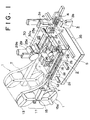
- FIG. 1 is a perspective view, with parts broken away, of the main part of an automatic heat-fusible tape piece attaching apparatus applied to a slide fastener chain manufacturing machine according to a typical embodiment of the invention.
- FIG. 2 is an enlarged cross-sectional view of FIG. 1. The remaining components other than those shown in these views are described in detail in the above-mentioned publications, so their detailed description is omitted here for clarity.
- the tape supply part includes a tape cassette 1 with a reel support part 11 and a tape guide part 12, a tape cassette support base 2 for supporting a plurality of tape cassettes 1 in row and for moving a desired tape cassette 1 to position in alignment with a thermoplastic tape attaching portion, and a tape piece fusing means 3 to be located in the travelling path of a slide fastener chain at a predetermined position within a range of movement of the tape cassette support base 2.
- the tape cassette 1 of the illustrated embodiment has a generally T-shape contour.
- a reel support part 11 has a bracket (not shown) supporting a set of upper and lower reels 13, and a tape guide part 12 horizontally extending forwardly (at the right in FIG. 2) from the center of the bracket.
- the non-illustrated bracket of the reel support part 11 has a pair of cantilevered shafts 14 on which the upper and lower tape reels 13 are detachably and rotatably mounted and which is equipped with a known removing and mounting mechanism.
- the tape guide part 12 is in the form of a square pillar; a back half portion 15 (leftside in FIG. 2) has a through hole 15a of rectangular cross section extending centrally and longitudinally, while the front half portion 16 (rightside in FIG. 2) is in the form of a generally square tube having a space 16a of rectangular cross section.
- the tape guide part 12 has a front end portion constituting a throat 17 having upper and lower tape passageways 17a.
- the tape guide part 12 has upper and lower guide levers 18 projecting substantially centrally from the back half portion 15 in opposite directions, each guide lever 18 having a pair of guide pins 18a.
- upper and lower guide rollers 19 and upper and lower tape return preventing members 20 are situated in order along the traveling path of tape.
- Each tape return preventing member 20 is of an L shape as shown in FIG. 2 and has a claw, at a front end in the direction of travel of the thermoplastic tape T, confronting the tape surface; the tape return preventing member 20 is vertically pivotable about the center of the L shape.
- a support base holding and releasing mechanism 21, and a pair of pressure rollers 22a, 22b are situated in order from the back side to the front side.
- Two walls are situated over the back and front pressure rollers 22a, 22b, respectively, and each wall has a cutout through which part of the respective pressure roller 22a, 22b is exposed to the outside.
- the pressure rollers 22a, 22b are rotatably mounted on the respective horizontal shafts in the space 16a.
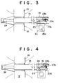
- FIGS. 3 and 4 show the support base holding and releasing mechanism 21 in operative position.
- the support base holding and releasing mechanism 21, as shown in FIGS. 3 and 4 has at a lower portion of the front end a locking claw 23a engageable with part of the tape cassette support base 2 and at an upper portion of the front end a lock member 23 having a cam contact 23b.
- the back end portion of the lock member 23 is pivotally supported in the space 16a so that its front end is pivotally movable vertically.
- the lower wall of the front half portion 16 has an opening at a position under the lock member 23.
- a compression spring 23c is mounted between the front end of the lock member 23 and the upper wall of the front half portion 16 to urge the front end of the lock member 23 to pivotally move normally downwardly.
- the support base holding and releasing mechanism 21 has an operation lever 24 for the lock member 23.
- the operation lever 24 has at its back end a right-angled operating end portion 24a as shown in FIGS. 2 to 4 and on the upper surface of its front end a cam surface 24b on which the cam contact 23 of the lock member 23 resiliently rests.
- the operation lever 24, with its front end directed forwardly, is inserted into the through hole 15a extending centrally through the back half portion 15 and is positioned in such a manner that the cam contact 23b resiliently rests on the cam surface 24b.
- the throat 17 or the front end solid portion of the tape guide part 12 has upper and lower tape passageways 17a which open to the front end of the throat 17.
- the throat 17 has in the front portion of its lower surface an engaging groove 17b in which engages a below-described tape cassette locking member 2g of the tape cassette support base 2.
- the tape cassette 1 of the above-mentioned construction can be applied not only to the apparatus for attaching the reinforcing tape pieces Tc to the space portions of a slide fastener chain S like the illustrated example, but also to an apparatus for attaching markers in the form of tape pieces to woven fabrics for usual inventory purposes. It also may be used in, for example, production of a fastener tape or a supply means for a tape-like article such as a surface fastener or a ribbon tape.
- the tape cassette support base 2 which is one of the components of this invention, will now be described in detail in connection with the illustrated example.
- the cassette support base 2 is in the form of a rectangular frame composed of two column blocks 2a, 2b connected by two connecting members 2c with a predetermined distance.
- the cassette support base 2 is situated and movable reciprocally alongside the traveling path of the slide fastener chain S as it is being positioned in a predetermined position parallel to the chain S.
- the tape cassette support base 2 is slidably supported on two guide rails 25a supported by a frame 25 and is restrictively moved along the guide rails 25a by a below-described drive means to thereby be positioned in a predetermined position.
- the tape cassette support base 2 On the upper surface of the tape cassette support base 2, there are formed a plurality of gutter-shape tape cassette mounts 2d for receiving a plurality of tape cassette 1 at predetermined distances, the tape cassette 1 being arranged perpendicularly to the traveling path of the slide fastener chain S.
- a plurality of locking holes 2e in which a drive pin 26c of a below-described support base drive 26 is engageable, at a predetermined pitch in the longitudinal direction, the number of the locking holes 2e being equal to that of the tape cassettes.
- a plurality of engaging holes 2f in which a positioning pin 28a of a below-described positioning means 28 is engageable, at the same pitch as the locking holes 2e, the number of the engaging holes 2f being equal to that of the locking holes 2e.
- a generally C-shape tape cassette locking member 2g is fastened by a screw with its one arm projecting upwardly.
- the tape cassette 1 For mounting the tape cassette 1 on the tape cassette support base 2, the tape cassette 1 is fitted in the generally C-shape tape cassette mount 2d of the tape cassette support base 2 and, at the same time, the tape cassette locking member 2g attached to the front edge of the front block 2b is brought into locking engagement with the locking groove 17b formed in the front end of the throat 17 of the tape cassette 1. At that time, the locking claw 23a of the locking member 23 is projected downwardly from the space 16a of the tape guide part 12 under the resilience of the compression spring 23c to engage the upper edge of the back block 2a. Therefore, the mounting of the tape cassette 1 can be performed in a simple snap action.
- the tape cassette 1 is mounted on the tape cassette support base 2, and upper and lower feed rollers 29, 30 are situated right above the back pressure roller 22a and right under the front pressure roller 22b, respectively, of the tape cassette 1 in the traveling paths of the thermoplastic tapes T.
- the feed rollers 29, 30 are operatively connected with drive motors 29a, 30a for driven rotation in synchronism.
- the upper and lower feed rollers 29, 30 together with the drive motors 29a, 30a are supported respectively by cylinders 33, 34 mounted on upper and lower frames 31, 32.
- the feed rollers 29, 30 are brought into contact with the respective exposed surfaces of the back and front pressure rollers 22a, 22b to rotate the pressure rollers 22a, 22b when feeding the tapes.
- the feed rollers 29, 30 are moved apart from the exposed surfaces of the pressure rollers 22a, 22b and are stopped rotating.
- a support base drive 26 is fixedly mounted on the upper surface of the base 35 via a suitable support means.
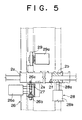
- the support base drive 26 includes a support base drive cylinder 26a and a drive pin actuating cylinder 26b as shown in FIGS. 1, 2 and 5.
- the drive pin actuating cylinder 26b is vertically attached to the end of the rod of the horizontally extending support base drive cylinder 26a.
- the drive pin actuating cylinder 26b is an upwardly stretchable one-way actuating cylinder, and a drive pin 26c vertically attached to the rod end is normally urged downwardly by a compression spring 27 to shrink the drive pin actuating cylinder 26b.
- the tape cassette support base 2 is moved reciprocally pitch by pitch of the locking hole 2e so that a desired tape cassette 1 on the tape cassette support base 2 is moved to a predetermined position, where the tape piece attaching portion is located, in the traveling path of the tape.
- the positioning means 28 upon every termination of movement of the tape cassette support base 2 by the support base drive 26, the positioning means 28 is actuated to define the support base position and to fix the support base 2 in that position.
- the positioning means 28 is fixedly mounted on the upper surface of the base 35 via a suitable support means in confronting relationship with the engaging hole 2f of the front block 2b.
- the positioning means 28 is in the form of a cylinder 28b having a retractable locking pin 28a as shown in FIGS. 2 and 5.
- the locking pin 28a is repeatedly projected from and retracted into the cylinder 28b, and finally the locking pin 28a comes into locking engagement with the corresponding engaging hole 2f of the front block 2b that has stopped moving, thereby locking the tape cassette support base 2 in that position.
- the locking pin 28a of the positioning means 28 is retractably projected by the actuation of the cylinder 28b.
- the inner surface of the engaging hole 2f may be inclined, and the locking pin 28a may be normally urged upwardly by, for example, a compression spring; in this case, engaging and disengaging of the locking pin 28a with respect to the engaging hole 2f can be performed easily.
- the foregoing description refers to the tape cassette according to one embodiment of this invention and to the main components of the automatic thermoplastic tape piece attaching apparatus of the invention using that tape cassette.
- the automatic thermoplastic tape piece attaching apparatus includes, in addition to the above-mentioned components, a tape piece fusing means 3, a cutter 5 and a gripper 4. But the tape piece fusing means 3, the cutter 5 and the gripper 4 are not peculiar to this invention and are known in the prior art; as their details are disclosed in the above-mentioned publications, only a simple description of these additional components is made here for clarity.
- the tape piece fusing means 3 includes an ultrasonic horn 3a and an anvil 3b and is situated at the crossing of the traveling path of the tape passing through the front and back feed rollers 29, 30 and the traveling path of a slide fastener chain S to which the tape pieces Tc are to be attached.
- the cutter 5 has cutting blades 5d, 5e vertically slidable on the back surface (leftside in FIG. 2) of the tape guide members 5a to 5c in the form of upper, central and lower blocks.
- the gripper 4 is situated between the ultrasonic horn 3a and the anvil 3b and is actuated, during the tape attaching, to hold a predetermined length of the tape pieces Tc, which have been cut off from the thermoplastic tape T, in a fixed position of front and back surfaces of the slide fastener chain S.
- the gripper 4 is held in inoperative position at all times except during the tape attaching.
- the support base drive 26 is actuated, according to the above-mentioned operation by an instruction from a non-illustrated control means, to move the tape cassette support base 2 so that the tape cassette 1 containing the thermoplastic tapes T to be attached for the first is positioned at the attaching portion in the traveling paths of the tapes.
- the locking pin 28a of the positioning means 28 comes into locking engagement with the corresponding engaging hole 2f formed in the front block 2b, thus holding the tape cassette support base 2 in that position.
- the upper and lower feed rollers 29, 30 come into contact with the reinforcing thermoplastic tapes T being guided on the respective exposed surfaces of the pressure rollers 22a, 22b of the tape cassette 1 and starts driven rotation to feed the thermoplastic tapes T forwards by a predetermined length.
- the slide fastener chain S traveling across in front of the tape cassette support base 2 is stopping with the reinforcing tape piece attaching portion reached in front of the tape cassette 1.
- the leading end portion of the thermoplastic tape T is guided by the tape guide members 5a to 5c so that its end is gripped by the gripper 4 situated in front of the tape cassette support base 2.
- the gripper 4 is moved rightwardly in FIG. 2 to bring the leading end portions of the reinforcing thermoplastic tapes T into contact with each of the front and back surfaces of the tape piece attaching portion of the slide fastener chain S.
- the cutter 5 is actuated to cut the leading end portion transversely of the tape T.
- the ultrasonic horn 3a and the anvil 3b of the tape piece fusing means 3 are moved toward each other to bring the leading end portion of the thermoplastic tape T against the attaching portion near the space of the slide fastener chain S, whereupon the thermoplastic tape and the slide fastener chain are fused together by ultrasonic process.
- the tape attaching of the tape piece fusing means 3 is performed only about the core cords of the slide fastener chain S and, at the same time, the core cords of the tape attaching portion are fused and separated.
- the cut-off piece of the thermoplastic tape is cut by a length corresponding to the width of the slide fastener chain S.
- the gripper 4 Upon termination of attaching the thermoplastic tape T, the gripper 4 releases the cut piece Tc of the thermoplastic tape T. Simultaneously with this cutting, the feed rollers 29, 30 make a predetermined number of reverse rotations to bring the cut end of the thermoplastic tape T back to the front end position of the throat 17 of the tape guide part 12, whereupon the feed rollers 29, 30 are moved apart from the tape cassette 1.
- the slide fastener chain S is moved to a non-illustrated heating and fusing means, by which the unattached region of the thermoplastic tape to be attached is fused to the front and back surfaces of the slide fastener chain S.
- the support base drive 26 and the positioning means 28 are activated again by an instruction from the control means to move the tape cassette support base 2 and, at the same time, to move the tape cassette 1 containing the thermoplastic tape T to be attached for the next, to the attaching portion in the traveling path of tape, thereby fixedly holding the tape cassette 1 there.
- the attaching process for the tape pieces Tc to a predetermined length of the second slide fastener chain S takes place automatically as the foregoing operation is repeated.
- the tape cassette of this invention can be applied to the apparatus for automatically attaching reinforcing tape pieces to a slide fastener chain like the foregoing embodiment as well as to many other applications.
- it may be used in an apparatus for attaching marks to cloths for inventory, a surface fastener manufacturing machine as well as a supply part of a ribbon tape processing machine, etc.
- the tape cassette of this invention is used in the supply part for a tape-like article, the tape together with the cassette can be exchanged with a new one in a simple operation. Since the tape exchange can be performed easily, it is possible not only to improve the rate of production but also to cope with recent flexible manufacturing.
- the tape cassette of this invention is applied to the automatic attaching machine for the thermoplastic tape, the conventional lot organizing work will be completely unnecessary, and also there will be no need of stopping the apparatus, thus it will be possible to meet the customers' demands sufficiently and speedily.
Landscapes
- Engineering & Computer Science (AREA)
- Textile Engineering (AREA)
- Slide Fasteners (AREA)
- Adhesive Tape Dispensing Devices (AREA)
- Replacement Of Web Rolls (AREA)
- Lining Or Joining Of Plastics Or The Like (AREA)
Description
Claims (5)
- A tape cassette equipped with a reel support part (11) rotatably supporting a tape reel (13), and a tape guide part (12) defining a tape guide path extending from said reel support part (11) in a direction of drawing a tape (T); characterized in that said tape guide part (12) has pressure rollers (22a, 22b) sectioning a part of said tape guide path, and a window through which part of said pressure rollers (22a, 22b) is exposed to the outside from said tape guide part (12).
- A tape cassette according to claim 1, wherein said reel support part (11) is arranged on upper and lower sides of said tape guide path, said tape guide part (12) having a square pillar, said tape guide path being divided into upper and lower steps within said tape guide part (12), said tape guide path being sectioned by said pressure rollers (22a, 22b) which are rotatably mounted at upstream and downstream positions, respectively, in said tape guide part (12).
- A tape cassette according to claim 1 or 2, wherein said tape guide part (12) further includes an operation lever (24) inserted through said tape guide path, and a lock member (23) operable, in response to the operation of said operation lever (24), to project into and retract from said tape guide path for engagement with and disengagement from a tape cassette mounting part.
- Use of a tape cassette according to one of claims 1 to 3 in an apparatus for automatically attaching heat-fusible tape pieces (Tc) successively onto a surface of a continuous strip (S) at predetermined distances while the strip (S) is being intermittently conveyed, said apparatus comprising:a) a tape cassette support base (2) situated alongside of a traveling path of the strip (S) and able to detachably support a plurality of said tape cassettes (1) at predetermined distances along the traveling path, said tape cassette support base (2) being movable along the traveling path for positioning; andb) drive rollers (29, 30) movably supported to come into and out of engagement with the respective exposed surfaces of said pressure rollers (22a, 22b).
- An apparatus for automatically attaching heat-fusible tape pieces (Tc) successively onto a surface of a continuous strip (S) at predetermined distances while the strip (S) is being intermittently conveyed, said apparatus comprising:a) a tape reel (13);b) a tape piece fusing means (3) situated on the travelling path of the strip (S);c) a gripping means (4) situated in an extension line passing through said tape fusing means for gripping a tape end of said tape reel (13); andd) a cutting means (5') situated between said tape guide part (12) and said tape fusing means (3) for cutting a predetermined length of tape piece off a thermoplastic tape (T) drawn from said tape reel (13);
characterized bye) a tape cassette (1) equipped with a reel support part (11) rotatably supporting said tape reel (13), and a tape guide part (12) in the form of a square pillar defining a tape guide path extending from said reel support part (11) in a direction of drawing a tape (T);f) a tape cassette support base (2) situated alongside of a travelling path of the strip (S) and able to detachably support a plurality of said tape cassettes (1) at predetermined distances along the travelling path, said tape cassette support base (2) being movable along the travelling path for positioning; andg) said tape guide part (12) having pressure rollers (22a, 22b) sectioning a part of said tape guide path, and a window in said square pillar through which part of said pressure rollers (22a, 22b) is exposed to the outside from said tape guide part (12), there being situated drive rollers (29, 30) movable to come into and out of engagement with the respective exposed surfaces of said pressure rollers (22a, 22b).
Applications Claiming Priority (2)
| Application Number | Priority Date | Filing Date | Title |
|---|---|---|---|
| JP297005/92 | 1992-11-06 | ||
| JP4297005A JPH06144689A (en) | 1992-11-06 | 1992-11-06 | Tape cassette and automatic sticking device for heat-welded tape piece |
Publications (2)
| Publication Number | Publication Date |
|---|---|
| EP0596528A1 EP0596528A1 (en) | 1994-05-11 |
| EP0596528B1 true EP0596528B1 (en) | 1998-02-04 |
Family
ID=17841019
Family Applications (1)
| Application Number | Title | Priority Date | Filing Date |
|---|---|---|---|
| EP93117995A Expired - Lifetime EP0596528B1 (en) | 1992-11-06 | 1993-11-05 | Tape cassette and automatic attaching apparatus for heat-fusible tape pieces |
Country Status (12)
| Country | Link |
|---|---|
| US (1) | US5746880A (en) |
| EP (1) | EP0596528B1 (en) |
| JP (1) | JPH06144689A (en) |
| KR (1) | KR0139832B1 (en) |
| BR (1) | BR9304507A (en) |
| CA (1) | CA2109142C (en) |
| DE (1) | DE69316829T2 (en) |
| ES (1) | ES2112945T3 (en) |
| FI (1) | FI934856A (en) |
| HK (1) | HK1005906A1 (en) |
| SG (1) | SG44861A1 (en) |
| ZA (1) | ZA938270B (en) |
Families Citing this family (15)
| Publication number | Priority date | Publication date | Assignee | Title |
|---|---|---|---|---|
| GB2313110A (en) * | 1996-05-18 | 1997-11-19 | Boris Siegmund Davis | Web feeding |
| US8458874B2 (en) * | 2009-06-09 | 2013-06-11 | Graphic Packaging International, Inc. | Article selection and placement assembly and method |
| CN103586329A (en) * | 2012-08-13 | 2014-02-19 | 梁鸿初 | Tooth arranging die |
| KR101364261B1 (en) * | 2013-02-01 | 2014-02-17 | 서강대학교산학협력단 | Apparatus for automatically forming micro bead substrate |
| CN104582522B (en) * | 2013-08-07 | 2017-03-15 | Ykk株式会社 | Reinforcing film supply casket and reinforcing film adhering device |
| WO2015145545A1 (en) * | 2014-03-24 | 2015-10-01 | Ykk株式会社 | Reinforcement film adhering device |
| CN106413459B (en) * | 2014-06-09 | 2019-08-20 | Ykk株式会社 | Reinforcing film then device and reinforcing film then method |
| CN105495877B (en) * | 2014-09-24 | 2018-04-20 | 成都瑞克西自动化技术有限公司 | One kind is vertical to put band machine |
| CN104326300A (en) * | 2014-10-24 | 2015-02-04 | 浙江东方基因生物制品有限公司 | Automatic adhesive tape sticking device |
| CN104444537B (en) * | 2014-11-24 | 2016-09-21 | 盐城市华森机械有限公司 | Based Intelligent Control high speed scouring pad microtome |
| CN104477694B (en) * | 2014-12-03 | 2017-01-11 | 湖北美的电冰箱有限公司 | Equipment for coating adhesive tape and refrigerator |
| CN105129494A (en) * | 2015-06-17 | 2015-12-09 | 东莞市三毛机械科技有限公司 | Metal zipper surface film pasting technology |
| CN108652144B (en) * | 2017-03-29 | 2020-11-10 | Ykk株式会社 | Zipper strip manufacturing device and method, and method for attaching reinforcing film to zipper strip |
| CN107415259B (en) * | 2017-09-30 | 2023-05-12 | 四川省绵竹兴远特种化工有限公司 | Recovery method and recovery device for U-shaped buckle remainder for emulsion explosive packaging |
| CN113942861B (en) * | 2020-07-15 | 2024-04-30 | Ykk株式会社 | Reinforcing film tape supply device |
Family Cites Families (7)
| Publication number | Priority date | Publication date | Assignee | Title |
|---|---|---|---|---|
| DE1753138A1 (en) * | 1968-01-12 | 1971-04-01 | Prym Werke William | Sales stand for zippers |
| US3939032A (en) * | 1974-12-27 | 1976-02-17 | Compensating Tension Controls, Inc. | Web butt splicer |
| US4242167A (en) * | 1978-10-26 | 1980-12-30 | B & H Manufacturing Company, Inc. | Labeling machine |
| JPS58188402A (en) * | 1982-04-28 | 1983-11-02 | ワイケイケイ株式会社 | Method and apparatus for attaching reinforcing strip to attachment part of opening and insert jig of slid fastener |
| US4462854A (en) * | 1983-09-21 | 1984-07-31 | William W. Holes | Process and apparatus for making a multi-pocketed album page |
| JPS62102934A (en) * | 1985-10-26 | 1987-05-13 | Yoshida Kogyo Kk <Ykk> | Cutting and connecting device for connection piece |
| FR2601996B1 (en) * | 1986-07-23 | 1991-08-23 | Nergeco Sa | SUPPORT AND TRANSMISSION MODULE FOR THE WINDING SHAFT OF A LIFT CURTAIN |
-
1992
- 1992-11-06 JP JP4297005A patent/JPH06144689A/en active Pending
-
1993
- 1993-10-25 CA CA002109142A patent/CA2109142C/en not_active Expired - Fee Related
- 1993-11-03 FI FI934856A patent/FI934856A/en unknown
- 1993-11-05 SG SG1996008873A patent/SG44861A1/en unknown
- 1993-11-05 ZA ZA938270A patent/ZA938270B/en unknown
- 1993-11-05 EP EP93117995A patent/EP0596528B1/en not_active Expired - Lifetime
- 1993-11-05 ES ES93117995T patent/ES2112945T3/en not_active Expired - Lifetime
- 1993-11-05 DE DE69316829T patent/DE69316829T2/en not_active Expired - Lifetime
- 1993-11-05 KR KR1019930023429A patent/KR0139832B1/en not_active IP Right Cessation
- 1993-11-05 BR BR9304507A patent/BR9304507A/en not_active Application Discontinuation
-
1995
- 1995-10-26 US US08/548,780 patent/US5746880A/en not_active Expired - Lifetime
-
1998
- 1998-06-05 HK HK98104969A patent/HK1005906A1/en not_active IP Right Cessation
Also Published As
| Publication number | Publication date |
|---|---|
| CA2109142A1 (en) | 1994-05-07 |
| AU5021393A (en) | 1994-05-26 |
| CA2109142C (en) | 1998-01-06 |
| US5746880A (en) | 1998-05-05 |
| AU664313B2 (en) | 1995-11-09 |
| BR9304507A (en) | 1994-06-28 |
| KR940012263A (en) | 1994-06-23 |
| JPH06144689A (en) | 1994-05-24 |
| DE69316829D1 (en) | 1998-03-12 |
| FI934856A0 (en) | 1993-11-03 |
| KR0139832B1 (en) | 1998-07-01 |
| FI934856A (en) | 1994-05-07 |
| EP0596528A1 (en) | 1994-05-11 |
| SG44861A1 (en) | 1997-12-19 |
| HK1005906A1 (en) | 1999-01-29 |
| DE69316829T2 (en) | 1998-09-03 |
| ES2112945T3 (en) | 1998-04-16 |
| ZA938270B (en) | 1994-06-23 |
Similar Documents
| Publication | Publication Date | Title |
|---|---|---|
| EP0596528B1 (en) | Tape cassette and automatic attaching apparatus for heat-fusible tape pieces | |
| CA1137285A (en) | Method of and apparatus for manufacturing slide fasteners | |
| EP0092789B1 (en) | Method of and apparatus for applying reinforcing film pieces to a slide fastener chain | |
| US4122594A (en) | Method for engaging a slider automatically on a slide fastener chain | |
| JPS5933365B2 (en) | Reinforcement band attaching device for slide fasteners with release fittings | |
| CN109068815B (en) | Slide fastener manufacturing apparatus and slide fastener manufacturing method | |
| CA1213422A (en) | Apparatus for cutting continuous slide fastener chain | |
| EP0172546B1 (en) | A space portion processing method and apparatus for a slide fastener chain | |
| EP0030706B1 (en) | Method of and apparatus for interengaging a pair of slide fastener stringers | |
| WO2020103377A1 (en) | Finger clamping mechanism having two clamping positions, band transporting, folding and rotating device, and automatic shoe-loop folding and sewing apparatus comprising same. | |
| EP0657120B1 (en) | Slider inserting apparatus for concealed slide fastener and concealed slide fastener finishing machine | |
| EP0145016A2 (en) | Apparatus for melt-forming bottom stop of slide fastener chain | |
| EP0052486B1 (en) | Apparatus for manufacturing electrical leads | |
| US4131993A (en) | Means for engaging a slider automatically on a slide fastener chain | |
| JPH06181806A (en) | Device for manufacturing slide fastener provided with selected number of sliders | |
| KR900006024B1 (en) | Method and apparatus for applying protective strip to and of slide fastener | |
| US5340043A (en) | Stator winding apparatus including winding form assemblies | |
| US4980968A (en) | Slider-installing system for slide-fastener manufacture | |
| US4062100A (en) | Method of and apparatus for removing coupling members of a slide-fastener stringer from a support tape | |
| EP0771538B1 (en) | Method of manufacturing slide fastener | |
| CA2109013C (en) | Apparatus for automatically cutting, welding and connecting ends of tape-like articles | |
| KR870000902Y1 (en) | Apparatus for finishing slide fastener chain with rein-forcing strip | |
| EP0193941B1 (en) | Method and apparatus for sewing a slide fastener to fabric pieces | |
| JPH10319842A (en) | Working device for tape having consecutively printed display tape pieces | |
| JPS6331947Y2 (en) |
Legal Events
| Date | Code | Title | Description |
|---|---|---|---|
| PUAI | Public reference made under article 153(3) epc to a published international application that has entered the european phase |
Free format text: ORIGINAL CODE: 0009012 |
|
| AK | Designated contracting states |
Kind code of ref document: A1 Designated state(s): BE CH DE ES FR GB IT LI NL SE |
|
| 17P | Request for examination filed |
Effective date: 19940825 |
|
| RAP1 | Party data changed (applicant data changed or rights of an application transferred) |
Owner name: YKK CORPORATION |
|
| GRAG | Despatch of communication of intention to grant |
Free format text: ORIGINAL CODE: EPIDOS AGRA |
|
| 17Q | First examination report despatched |
Effective date: 19970312 |
|
| GRAG | Despatch of communication of intention to grant |
Free format text: ORIGINAL CODE: EPIDOS AGRA |
|
| GRAG | Despatch of communication of intention to grant |
Free format text: ORIGINAL CODE: EPIDOS AGRA |
|
| GRAH | Despatch of communication of intention to grant a patent |
Free format text: ORIGINAL CODE: EPIDOS IGRA |
|
| GRAH | Despatch of communication of intention to grant a patent |
Free format text: ORIGINAL CODE: EPIDOS IGRA |
|
| GRAA | (expected) grant |
Free format text: ORIGINAL CODE: 0009210 |
|
| AK | Designated contracting states |
Kind code of ref document: B1 Designated state(s): BE CH DE ES FR GB IT LI NL SE |
|
| ITF | It: translation for a ep patent filed |
Owner name: JACOBACCI & PERANI S.P.A. |
|
| REG | Reference to a national code |
Ref country code: CH Ref legal event code: NV Representative=s name: BOVARD AG PATENTANWAELTE Ref country code: CH Ref legal event code: EP |
|
| REF | Corresponds to: |
Ref document number: 69316829 Country of ref document: DE Date of ref document: 19980312 |
|
| ET | Fr: translation filed | ||
| REG | Reference to a national code |
Ref country code: ES Ref legal event code: FG2A Ref document number: 2112945 Country of ref document: ES Kind code of ref document: T3 |
|
| PGFP | Annual fee paid to national office [announced via postgrant information from national office to epo] |
Ref country code: SE Payment date: 19980914 Year of fee payment: 6 Ref country code: BE Payment date: 19980914 Year of fee payment: 6 |
|
| PGFP | Annual fee paid to national office [announced via postgrant information from national office to epo] |
Ref country code: CH Payment date: 19981110 Year of fee payment: 6 |
|
| PLBE | No opposition filed within time limit |
Free format text: ORIGINAL CODE: 0009261 |
|
| STAA | Information on the status of an ep patent application or granted ep patent |
Free format text: STATUS: NO OPPOSITION FILED WITHIN TIME LIMIT |
|
| 26N | No opposition filed | ||
| PG25 | Lapsed in a contracting state [announced via postgrant information from national office to epo] |
Ref country code: NL Free format text: LAPSE BECAUSE OF NON-PAYMENT OF DUE FEES Effective date: 19990601 |
|
| NLV4 | Nl: lapsed or anulled due to non-payment of the annual fee |
Effective date: 19990601 |
|
| PG25 | Lapsed in a contracting state [announced via postgrant information from national office to epo] |
Ref country code: SE Free format text: LAPSE BECAUSE OF NON-PAYMENT OF DUE FEES Effective date: 19991106 |
|
| PG25 | Lapsed in a contracting state [announced via postgrant information from national office to epo] |
Ref country code: LI Free format text: LAPSE BECAUSE OF NON-PAYMENT OF DUE FEES Effective date: 19991130 Ref country code: CH Free format text: LAPSE BECAUSE OF NON-PAYMENT OF DUE FEES Effective date: 19991130 Ref country code: BE Free format text: LAPSE BECAUSE OF NON-PAYMENT OF DUE FEES Effective date: 19991130 |
|
| BERE | Be: lapsed |
Owner name: YKK CORP. Effective date: 19991130 |
|
| REG | Reference to a national code |
Ref country code: CH Ref legal event code: PL |
|
| EUG | Se: european patent has lapsed |
Ref document number: 93117995.6 |
|
| REG | Reference to a national code |
Ref country code: GB Ref legal event code: IF02 |
|
| PGFP | Annual fee paid to national office [announced via postgrant information from national office to epo] |
Ref country code: ES Payment date: 20091125 Year of fee payment: 17 Ref country code: DE Payment date: 20091029 Year of fee payment: 17 |
|
| PGFP | Annual fee paid to national office [announced via postgrant information from national office to epo] |
Ref country code: IT Payment date: 20091112 Year of fee payment: 17 Ref country code: GB Payment date: 20091104 Year of fee payment: 17 Ref country code: FR Payment date: 20091123 Year of fee payment: 17 |
|
| GBPC | Gb: european patent ceased through non-payment of renewal fee |
Effective date: 20101105 |
|
| REG | Reference to a national code |
Ref country code: FR Ref legal event code: ST Effective date: 20110801 |
|
| REG | Reference to a national code |
Ref country code: DE Ref legal event code: R119 Ref document number: 69316829 Country of ref document: DE Effective date: 20110601 Ref country code: DE Ref legal event code: R119 Ref document number: 69316829 Country of ref document: DE Effective date: 20110531 |
|
| PG25 | Lapsed in a contracting state [announced via postgrant information from national office to epo] |
Ref country code: DE Free format text: LAPSE BECAUSE OF NON-PAYMENT OF DUE FEES Effective date: 20110531 |
|
| PG25 | Lapsed in a contracting state [announced via postgrant information from national office to epo] |
Ref country code: FR Free format text: LAPSE BECAUSE OF NON-PAYMENT OF DUE FEES Effective date: 20101130 |
|
| PG25 | Lapsed in a contracting state [announced via postgrant information from national office to epo] |
Ref country code: GB Free format text: LAPSE BECAUSE OF NON-PAYMENT OF DUE FEES Effective date: 20101105 |
|
| PG25 | Lapsed in a contracting state [announced via postgrant information from national office to epo] |
Ref country code: IT Free format text: LAPSE BECAUSE OF NON-PAYMENT OF DUE FEES Effective date: 20101105 |
|
| REG | Reference to a national code |
Ref country code: ES Ref legal event code: FD2A Effective date: 20120110 |
|
| PG25 | Lapsed in a contracting state [announced via postgrant information from national office to epo] |
Ref country code: ES Free format text: LAPSE BECAUSE OF NON-PAYMENT OF DUE FEES Effective date: 20101106 |