EP0595987B1 - Hydrocracking with ultra large pore size catalysts - Google Patents
Hydrocracking with ultra large pore size catalysts Download PDFInfo
- Publication number
- EP0595987B1 EP0595987B1 EP92916471A EP92916471A EP0595987B1 EP 0595987 B1 EP0595987 B1 EP 0595987B1 EP 92916471 A EP92916471 A EP 92916471A EP 92916471 A EP92916471 A EP 92916471A EP 0595987 B1 EP0595987 B1 EP 0595987B1
- Authority
- EP
- European Patent Office
- Prior art keywords
- process according
- hydrocracking
- catalyst
- grams
- zeolite
- Prior art date
- Legal status (The legal status is an assumption and is not a legal conclusion. Google has not performed a legal analysis and makes no representation as to the accuracy of the status listed.)
- Expired - Lifetime
Links
Images

Classifications
-
- C—CHEMISTRY; METALLURGY
- C10—PETROLEUM, GAS OR COKE INDUSTRIES; TECHNICAL GASES CONTAINING CARBON MONOXIDE; FUELS; LUBRICANTS; PEAT
- C10G—CRACKING HYDROCARBON OILS; PRODUCTION OF LIQUID HYDROCARBON MIXTURES, e.g. BY DESTRUCTIVE HYDROGENATION, OLIGOMERISATION, POLYMERISATION; RECOVERY OF HYDROCARBON OILS FROM OIL-SHALE, OIL-SAND, OR GASES; REFINING MIXTURES MAINLY CONSISTING OF HYDROCARBONS; REFORMING OF NAPHTHA; MINERAL WAXES
- C10G47/00—Cracking of hydrocarbon oils, in the presence of hydrogen or hydrogen- generating compounds, to obtain lower boiling fractions
- C10G47/02—Cracking of hydrocarbon oils, in the presence of hydrogen or hydrogen- generating compounds, to obtain lower boiling fractions characterised by the catalyst used
- C10G47/10—Cracking of hydrocarbon oils, in the presence of hydrogen or hydrogen- generating compounds, to obtain lower boiling fractions characterised by the catalyst used with catalysts deposited on a carrier
- C10G47/12—Inorganic carriers
- C10G47/16—Crystalline alumino-silicate carriers
-
- B—PERFORMING OPERATIONS; TRANSPORTING
- B01—PHYSICAL OR CHEMICAL PROCESSES OR APPARATUS IN GENERAL
- B01J—CHEMICAL OR PHYSICAL PROCESSES, e.g. CATALYSIS OR COLLOID CHEMISTRY; THEIR RELEVANT APPARATUS
- B01J29/00—Catalysts comprising molecular sieves
- B01J29/005—Mixtures of molecular sieves comprising at least one molecular sieve which is not an aluminosilicate zeolite, e.g. from groups B01J29/03 - B01J29/049 or B01J29/82 - B01J29/89
-
- B—PERFORMING OPERATIONS; TRANSPORTING
- B01—PHYSICAL OR CHEMICAL PROCESSES OR APPARATUS IN GENERAL
- B01J—CHEMICAL OR PHYSICAL PROCESSES, e.g. CATALYSIS OR COLLOID CHEMISTRY; THEIR RELEVANT APPARATUS
- B01J29/00—Catalysts comprising molecular sieves
- B01J29/04—Catalysts comprising molecular sieves having base-exchange properties, e.g. crystalline zeolites
- B01J29/041—Mesoporous materials having base exchange properties, e.g. Si/Al-MCM-41
- B01J29/042—Mesoporous materials having base exchange properties, e.g. Si/Al-MCM-41 containing iron group metals, noble metals or copper
- B01J29/044—Iron group metals or copper
-
- B—PERFORMING OPERATIONS; TRANSPORTING
- B01—PHYSICAL OR CHEMICAL PROCESSES OR APPARATUS IN GENERAL
- B01J—CHEMICAL OR PHYSICAL PROCESSES, e.g. CATALYSIS OR COLLOID CHEMISTRY; THEIR RELEVANT APPARATUS
- B01J29/00—Catalysts comprising molecular sieves
- B01J29/04—Catalysts comprising molecular sieves having base-exchange properties, e.g. crystalline zeolites
- B01J29/041—Mesoporous materials having base exchange properties, e.g. Si/Al-MCM-41
- B01J29/045—Mesoporous materials having base exchange properties, e.g. Si/Al-MCM-41 containing arsenic, antimony, bismuth, vanadium, niobium, tantalum, polonium, chromium, molybdenum, tungsten, manganese, technetium or rhenium
-
- B—PERFORMING OPERATIONS; TRANSPORTING
- B01—PHYSICAL OR CHEMICAL PROCESSES OR APPARATUS IN GENERAL
- B01J—CHEMICAL OR PHYSICAL PROCESSES, e.g. CATALYSIS OR COLLOID CHEMISTRY; THEIR RELEVANT APPARATUS
- B01J29/00—Catalysts comprising molecular sieves
- B01J29/04—Catalysts comprising molecular sieves having base-exchange properties, e.g. crystalline zeolites
- B01J29/06—Crystalline aluminosilicate zeolites; Isomorphous compounds thereof
- B01J29/08—Crystalline aluminosilicate zeolites; Isomorphous compounds thereof of the faujasite type, e.g. type X or Y
-
- B—PERFORMING OPERATIONS; TRANSPORTING
- B01—PHYSICAL OR CHEMICAL PROCESSES OR APPARATUS IN GENERAL
- B01J—CHEMICAL OR PHYSICAL PROCESSES, e.g. CATALYSIS OR COLLOID CHEMISTRY; THEIR RELEVANT APPARATUS
- B01J29/00—Catalysts comprising molecular sieves
- B01J29/04—Catalysts comprising molecular sieves having base-exchange properties, e.g. crystalline zeolites
- B01J29/06—Crystalline aluminosilicate zeolites; Isomorphous compounds thereof
- B01J29/40—Crystalline aluminosilicate zeolites; Isomorphous compounds thereof of the pentasil type, e.g. types ZSM-5, ZSM-8 or ZSM-11, as exemplified by patent documents US3702886, GB1334243 and US3709979, respectively
-
- B—PERFORMING OPERATIONS; TRANSPORTING
- B01—PHYSICAL OR CHEMICAL PROCESSES OR APPARATUS IN GENERAL
- B01J—CHEMICAL OR PHYSICAL PROCESSES, e.g. CATALYSIS OR COLLOID CHEMISTRY; THEIR RELEVANT APPARATUS
- B01J29/00—Catalysts comprising molecular sieves
- B01J29/04—Catalysts comprising molecular sieves having base-exchange properties, e.g. crystalline zeolites
- B01J29/06—Crystalline aluminosilicate zeolites; Isomorphous compounds thereof
- B01J29/70—Crystalline aluminosilicate zeolites; Isomorphous compounds thereof of types characterised by their specific structure not provided for in groups B01J29/08 - B01J29/65
- B01J29/72—Crystalline aluminosilicate zeolites; Isomorphous compounds thereof of types characterised by their specific structure not provided for in groups B01J29/08 - B01J29/65 containing iron group metals, noble metals or copper
- B01J29/76—Iron group metals or copper
-
- B—PERFORMING OPERATIONS; TRANSPORTING
- B01—PHYSICAL OR CHEMICAL PROCESSES OR APPARATUS IN GENERAL
- B01J—CHEMICAL OR PHYSICAL PROCESSES, e.g. CATALYSIS OR COLLOID CHEMISTRY; THEIR RELEVANT APPARATUS
- B01J29/00—Catalysts comprising molecular sieves
- B01J29/04—Catalysts comprising molecular sieves having base-exchange properties, e.g. crystalline zeolites
- B01J29/06—Crystalline aluminosilicate zeolites; Isomorphous compounds thereof
- B01J29/70—Crystalline aluminosilicate zeolites; Isomorphous compounds thereof of types characterised by their specific structure not provided for in groups B01J29/08 - B01J29/65
- B01J29/78—Crystalline aluminosilicate zeolites; Isomorphous compounds thereof of types characterised by their specific structure not provided for in groups B01J29/08 - B01J29/65 containing arsenic, antimony, bismuth, vanadium, niobium, tantalum, polonium, chromium, molybdenum, tungsten, manganese, technetium or rhenium
-
- B—PERFORMING OPERATIONS; TRANSPORTING
- B01—PHYSICAL OR CHEMICAL PROCESSES OR APPARATUS IN GENERAL
- B01J—CHEMICAL OR PHYSICAL PROCESSES, e.g. CATALYSIS OR COLLOID CHEMISTRY; THEIR RELEVANT APPARATUS
- B01J29/00—Catalysts comprising molecular sieves
- B01J29/04—Catalysts comprising molecular sieves having base-exchange properties, e.g. crystalline zeolites
- B01J29/06—Crystalline aluminosilicate zeolites; Isomorphous compounds thereof
- B01J29/80—Mixtures of different zeolites
-
- B—PERFORMING OPERATIONS; TRANSPORTING
- B01—PHYSICAL OR CHEMICAL PROCESSES OR APPARATUS IN GENERAL
- B01J—CHEMICAL OR PHYSICAL PROCESSES, e.g. CATALYSIS OR COLLOID CHEMISTRY; THEIR RELEVANT APPARATUS
- B01J2229/00—Aspects of molecular sieve catalysts not covered by B01J29/00
- B01J2229/10—After treatment, characterised by the effect to be obtained
- B01J2229/26—After treatment, characterised by the effect to be obtained to stabilize the total catalyst structure
-
- B—PERFORMING OPERATIONS; TRANSPORTING
- B01—PHYSICAL OR CHEMICAL PROCESSES OR APPARATUS IN GENERAL
- B01J—CHEMICAL OR PHYSICAL PROCESSES, e.g. CATALYSIS OR COLLOID CHEMISTRY; THEIR RELEVANT APPARATUS
- B01J2229/00—Aspects of molecular sieve catalysts not covered by B01J29/00
- B01J2229/30—After treatment, characterised by the means used
- B01J2229/36—Steaming
-
- B—PERFORMING OPERATIONS; TRANSPORTING
- B01—PHYSICAL OR CHEMICAL PROCESSES OR APPARATUS IN GENERAL
- B01J—CHEMICAL OR PHYSICAL PROCESSES, e.g. CATALYSIS OR COLLOID CHEMISTRY; THEIR RELEVANT APPARATUS
- B01J2229/00—Aspects of molecular sieve catalysts not covered by B01J29/00
- B01J2229/30—After treatment, characterised by the means used
- B01J2229/42—Addition of matrix or binder particles
-
- B—PERFORMING OPERATIONS; TRANSPORTING
- B01—PHYSICAL OR CHEMICAL PROCESSES OR APPARATUS IN GENERAL
- B01J—CHEMICAL OR PHYSICAL PROCESSES, e.g. CATALYSIS OR COLLOID CHEMISTRY; THEIR RELEVANT APPARATUS
- B01J29/00—Catalysts comprising molecular sieves
- B01J29/03—Catalysts comprising molecular sieves not having base-exchange properties
- B01J29/0308—Mesoporous materials not having base exchange properties, e.g. Si-MCM-41
-
- B—PERFORMING OPERATIONS; TRANSPORTING
- B01—PHYSICAL OR CHEMICAL PROCESSES OR APPARATUS IN GENERAL
- B01J—CHEMICAL OR PHYSICAL PROCESSES, e.g. CATALYSIS OR COLLOID CHEMISTRY; THEIR RELEVANT APPARATUS
- B01J29/00—Catalysts comprising molecular sieves
- B01J29/04—Catalysts comprising molecular sieves having base-exchange properties, e.g. crystalline zeolites
- B01J29/06—Crystalline aluminosilicate zeolites; Isomorphous compounds thereof
- B01J29/08—Crystalline aluminosilicate zeolites; Isomorphous compounds thereof of the faujasite type, e.g. type X or Y
- B01J29/084—Y-type faujasite
Definitions
- This invention relates to a process for hydrocracking and more particularly to a process for catalytically hydrocracking petroleum feedstocks to produce distillate products of improved characteristics, especially low nitrogen content.
- Hydrocracking is a process which has achieved widespread use in petroleum refining for converting various petroleum fractions to lighter and more valuable products, especially distillates such as jet fuels, diesel oils and heating oils. Hydrocracking is generally carried out in conjunction with an initial hydrotreating step in which the heteroatom-containing impurities in the feed are hydrogenated without a significant degree of bulk conversion. During this initial step, the heteroatoms, principally nitrogen and sulfur, are converted to inorganic form (ammonia, hydrogen-sulfide) and these gases may be removed prior to the subsequent hydrocracking step although the two stages may be combined in cascade without interstage separation as, for example, in the Unicracking-JHC process and in the moderate pressure hydrocracking process described in U.S. Patent No. 4,435,275.
- inorganic form ammonia, hydrogen-sulfide
- the hydrotreated feedstock is contacted with a bifunctional catalyst which possesses both acidic and hydrogenation/dehydrogenation functionality.
- the characteristic hydrocracking reactions occur in the presence of the catalyst.
- Polycyclic aromatics in the feed are hydrogenated, and ring opening of aromatic and napthenic rings takes place together with dealkylation. Further hydrogenation may take place upon opening of the aromatic rings.
- the polycyclic aromatics in the feed will be hydrocracked to paraffinic materials or, under less severe conditions, to monocylic aromatics as well as paraffins.
- Naphthenic and aromatic rings may be present in the product, for example, as substituted naphthenes and substituted polycyclic aromatics in the higher boiling products, depending upon the degree of operational severity.
- the bifunctional catalyst typically comprises a metal component which provides the hydrogenation/dehydrogenation functionality and a porous, inorganic oxide support provides the acidic function.
- the metal component typically comprises a combination of metals from Groups IVA, VIA and VIIIA of the Periodic Table (IUPAC Table) although single metals may also be encountered. Combinations of metals from Groups VIA and VIIIA are especially preferred, such as nickel-molybdenum, cobalt-molybdenum, nickel-tungsten, cobalt-nickel- molybdenum and nickel-tungsten-titanium.
- Noble metals of Group VIIIA especially platinum or palladium may be encountered but are not typically used for treating high boiling feeds which tend to contain significant quantities of heteroatoms which function as poisons for these metals.
- the porous support which provides the acidic functionality in the catalyst may comprise either an amorphous or a crystalline material or both.
- Amorphous materials have significant advantages for processing very high boiling feeds which contain significant quantities of bulky polycyclic materials (aromatics as well as polynapthenes) since the amorphous materials usually possesses pores extending over a wide range of sizes and the larger pores, frequently in the size range of 100 to 400 Angstroms ( ⁇ ) are large enough to provide entry of the bulky components of the feed into the interior structure of the material where the acid-catalyzed reactions may take place.
- Typical amorphous materials of this kind include alumina and silica-alumina and mixtures of the two, possibly modified with other inorganic oxides such as silica, magnesia or titania.
- Crystalline materials especially the large pore size zeolites such as zeolites X and Y, have been found to be useful for a number of hydrocracking applications since they have the advantage, as compared to the amorphous materials, of possessing a greater degree of activity, which enables the hydrocracking to be carried out at lower temperatures at which the accompanying hydrogenation reactions are thermodynamically favored.
- the crystalline catalysts tend to be more stable in operation than the amorphous materials such as alumina.
- the crystalline materials may, however, not be suitable for all applications since even the largest pore sizes in these materials, typically 7.4 ⁇ in the X and Y zeolites, are too small to permit access by various bulky species in the feed. For this reason, hydrocracking of residuals fractions and high boiling feeds has generally required an amorphous catalyst of rather lower activity.
- EP-A-512 026 the content of which was published on 8 Aug 91, discloses crystalline mesoporous materials and their use to hydrocrack feeds such as residual oils.
- the crystalline hydrocracking catalysts generally tend to produce significant quantities of gasoline boiling range materials (approximately 330°F-, 165°C-) materials as product. Since hydrocracked gasolines tend to be of relatively low octane and require further treatment as by reforming before the product can be blended into the refinery gasoline pool, hydrocracking is usually not an attractive route for the production of gasoline. On the other hand, it is favorable to the production of distillate fractions, especially jet fuels, heating oils and diesel fuels since the hydrocracking process reduces the heteroatom impurities characteristically present in these fractions to the low level desirable for these products.
- the selectivity of crystalline aluminosilicate catalysts for distillate production may be improved by the use of highly siliceous zeolites, for example, the zeolites possessing a silica: alumina ratio of 50:1 or more, as described in U.S. Patent No. 4,820,402 (Partridge et al), but even with this advance in the technology, it would still be desirable to integrate the characteristics of the amorphous materials with their large pore sizes capable of accommodating the bulky components of typical hydrocracking feeds, with the activity of the zeolite catalysts.
- the zeolite content of the catalyst is conventionally as high as possible for the desired acidity; conversely the amount of matrix which supports the metal component is limited and as the proportion of zeolite in the catalyst increases, the amount of support available for the metal component decreases with the result that the hydrogenation activity becomes limited at the high zeolite loadings requisite to fuels hydrocracking.
- mesoporous siliceous materials having a novel and unique pore geometry may be used as the basis for hydrocracking catalysts of excellent properties.
- These mesoporous siliceous materials are characterized by a regular, crystalline microstructure with uniform pores having a cell diameter greater than 13 ⁇ and typically in the range of 20 to 100 ⁇
- These crystalline catalytic materials are readily characterized by their X-ray diffraction pattern which includes at least one peak having a relative intensity of 100; they have a high surface area and porosity which is manifested by a benzene adsorption greater than 15 g. benzene per 100 g.
- crystalline material at 6.7 kPa (50 torr) and 25°C.
- MCM-41 a new metallosilicate having a structure identified as MCM-41 which is usually synthesized with Br ⁇ nsted acid sites by incorporating a tetrahedrally coordinated trivalent element such as Al, Ga, B, or Fe within the silicate framework.
- Aluminosilicate materials of this type possess good thermal and chemical stability, properties favored for acid catalysis.
- the unique structure of these materials enables hydrocracking to be carried out under advantageous conditions with excellent results, especially in the reduction of heteroatom contaminants.
- the hydrocracking is preferably carried out under moderate pressure conditions, typically at total system pressures of under 1500 psig (10,445 kPa abs) and in most cases under 1000 psig (7,000 kPa abs) or even lower, for example, under 800 psig (5620 kPa abs) using the mesoporous catalysts.
- These catalysts exhibit kerosene and distillate yield selectivities in fuels hydrocracking which are comparable to current state-of-the-art amorphous catalysts currently used in petroleum refineries.
- the bottoms produced by the present invention have product quality benefits (lower nitrogen and aromatics) compared to those produced from amorphous catalysts.
- the desirable features of the ultra-large pore size hydroprocessing catalysts and the zeolite hydroprocessing catalysts may be combined by utilizing the ultra-large poor size material to provide additional surface area for the support of the metal component of the catalyst while a zeolite provides the acidic functionality required for cracking activity.
- the resulting combination catalyst enables both the metal loading and the acidic functionality of the catalyst to be optimized with the result that good hydrogenation activity is obtained together with good cracking activity and the resulting catalysts are useful in fuels hydrocracking processes, especially where high conversion levels are desired.
- a hydrocracking catalyst which comprises a metal hydrogenation/dehydrogenation component, a mesoporous siliceous material and a crystalline zeolite, preferably a large pore size zeolite such as zeolite USY.
- a hydrocarbon feed normally a high-boiling feed such as a gas oil
- the hydrocracking is preferably carried out under moderate pressure conditions and is capable of producing high-quality kerosene and distillate with good selectivity.
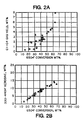
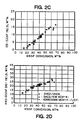
- Figures 1 and 2 are graphical representations of the performance of the present hydrocracking catalysts, as described below in the Examples.
- the feedstock for the present process is a heavy oil fraction having an initial boiling point no higher than 345°C (650°F), although the present catalysts may also be used for hydrocracking lighter fractions such as naphtha or Udex raffinates or extracts and light cycle oil.
- Suitable high boiling feedstocks include gas oils such as vacuum gas oil, coker gas oil, lube extracts produced by the solvent extraction of lube oil fractions using solvents such as phenol, furfural or N-methyl-pyrrolidone, visbreaker oil or deasphalted oil.
- the feedstock will have an extended boiling range, e.g.
- 345° to 590°C (650° to 1100°F), but may be of more limited ranges with certain feedstocks or alternatively may include or comprise non-distillable i.e. residual, fractions.
- the heteroatom is not critical: the nitrogen content will generally be in the range 200 to 1500 ppmw.
- the sulfur content is not critical and typically may range as high as 5 percent by weight. Sulfur contents of 2.0 to 3.0 percent by weight are common.
- Typical feedstock boiling ranges will be 345° to 565°C (650° to 1050°F) or 345° to 510°C (650° to 950°F) but oils with a narrower boiling range may, of course, be processed, for example, those with a boiling range of 345° to 455°C (650° to 850°F).
- Heavy gas oils are often of this kind as are heavy cycle oils and other non-residual materials.
- the heavy oil feeds will comprise high molecular weight long chain paraffins and high molecular weight aromatics with a large proportion of fused ring aromatics.
- the fused ring aromatics are hydrogenated by the metal function on the catalyst, naphthenes are cracked by the acidic catalyst and the paraffinic cracking products, together with paraffinic components of the initial feedstock undergo isomerization to iso-paraffins with some cracking to lower molecular weight materials.
- Hydrogenation of unsaturated side chains on the monocyclic cracking residues of the original polycyclics is catalyzed by the metal component of the hydrocracking catalyst to form substituted monocyclic aromatics which are highly desirable end products.
- High quality fuel products exemplified by low sulfur, high hydrogen content, high cetane number (30-45) diesel fuel oils and similar high smoke point jet fuels (typical smoke point 20-25 mm) may be obtained with suitable VGO feeds.
- the feedstock is heated to an elevated temperature and is then passed over the hydrotreating and hydrocracking catalysts in the presence of hydrogen. Because the thermodynamics of hydrocracking become unfavorable at temperatures above 450°C (850°F) temperatures above this value will not normally be used. In addition, because the hydrotreating and hydrocracking reactions are exothermic, the feedstock need not be heated to the temperature desired in the catalyst bed which is normally in the range 290°, usually 360° to 440°C (550°, usually 675° to 825°F). At the beginning of the process cycle, the temperature employed will be at the lower end of this range but as the catalyst ages, the temperature may be increased in order to maintain the desired degree of activity.
- the heavy oil feedstock is passed over the catalysts in the presence of hydrogen.
- the space velocity of the oil is usually in the range 0.1 to 10 LHSV preferably 0.2 to 2.0 LHSV and the hydrogen circulation rate from 250 to 1000 n.1.1 -1 . (1400 to 5600 SCF/bbl) and more usually from 300 to 800 (1685 to 4500 SCF/bbl).
- Hydrogen partial pressure is usually at least 75% of the total system pressure with reactor inlet pressures normally being in the range of 400 to 1500 psig (2860 to 10445 kPa abs), more commonly from 800 to 1200 psig (5620 to 8375 kPa abs) for low to moderate pressure operation, which is the preferred mode with the present catalyst, although high pressure operation above 1500 psig (10445 kPa abs) is also feasible and with similar advantages, especially for fuels hydrocracking.
- pressures from 1500 to 5000 psig (10445 to 34575 kPa abs) are typical although higher pressures may also be utilized with the upper limit usually being set by equipment constraints.
- the pressure When operating at low conversions, for example, less than 50 wt % conversion to 345°C- (650°F-) products, the pressure may be considerably lower than normal, conventional practices. We have found that total system pressures of 700 to 1200 psig (4930 to 8375 kPa abs) are satisfactory, as compared to the pressures of at least 1500 psig (10445 kPa) normally used in commercial hydrocracking processes. Low conversion may be obtained by suitable selection of other reaction parameters, e.g., temperature, space velocity, choice of catalyst, and even lower pressures may be used. Low pressures are desirable from the point of view of equipment design since less massive and consequently cheaper equipment will be adequate. Similarly, lower pressures usually influence less aromatic saturation and thereby permit economy in the total amount of hydrogen consumed in the process.
- the relative proportions of the hydrocracking and the hydrotreating catalysts may be varied according to the feedstock in order to convert the nitrogen in the feedstock to ammonia before the charge passes to the hydrocracking step; the object is to reduce the nitrogen level of the charge to a point where the desired degree of conversion by the hydrocracking catalyst is attained with the optimum combination of space velocity and reaction temperature.
- the greater the amount of nitrogen in the feed the greater then will be the proportion of hydrotreating (denitrogenation) catalyst relative to the hydrocracking catalyst.
- the catalyst ratio may be as low as 10:90 (by volume, denitrogenation: hydrocracking). In general, however, ratios between 25:75 to 75:25 will be used. With many stocks an approximately equal volume ratio will be suiable, e.g. 40:60, 50:50 or 60:40.
- the overall conversion may be maintained at varying levels depending on the nature of the feed and on the desired product characteristics. It is possible to operate the process at a low conversion level, less than 50 wt % to lower boiling products, usually 340°C- (650°F-) products from the heavy oil feedstocks used while still maintaining satisfactory product quality.
- the conversion may, of course, be maintained at even lower levels, e.g. 30 or 40 percent by weight.
- the degree of cracking to gas (C 4 -) which occurs at these low conversion figures is correspondingly low and so is the conversion to naphtha (200°C-, 400°F-); the distillate selectivity of the process is accordingly high and overcracking to lighter and less desired products is minimized. It is believed that in cascade operation this effect is procured, in part, by the effect of the ammonia carried over from the first stage. Control of conversion may be effected by conventional expedients such as control of temperature, pressure, space velocity and other reaction parameters.
- the present process has the advantage that it may be operated under low to moderate pressure conditions in existing low pressure equipment. For example, if a desulfurizer is available, it may be used with relatively few modifications since the present process may be operated at low pressures comparable to the low severity conditions used in desulfurization. This may enable substantial savings in capital costs to be made since existing refinery units may be adapted to increase the pool of distillate products.
- the feed is preferably passed over a hydrotreating catalyst before the hydrocracking catalyst in order to convert nitrogen and sulfur containing compounds to gaseous ammonia and hydrogen sulfide.
- hydrocracking is minimized but partial hydrogenation of polycyclic aromatics proceeds, together with a limited degree of conversion to lower boiling (345°C-, 650°F-) products.
- the catalyst used in this stage may be a conventional denitrogenation (denitrification) catalyst.
- Catalysts of this type are relatively immune to poisoning by the nitrogenous and sulfurous impurities in the feedstock and, generally comprise a non-noble metal component supported on an amorphous, porous carrier such as silica, alumina, silica-alumina or silica-magnesia. Because extensive cracking is not desired in this stage of the process, the acidic functionality of the carrier may be relatively low compared to that of the subsequent hydrocracking catalyst.
- the metal component may be a single metal from Groups VIA and VIIIA of the Periodic Table such as nickel, cobalt, chromium, vanadium, molybdenum, tungsten, or a combination of metals such as nickel-molybdenum, cobalt-nickel-molybdenum, cobalt-molybdenum, nickel-tungsten or nickel-tungsten-titanium.
- the metal component will be selected for good hydrogen transfer activity; the catalyst as a whole will have good hydrogen transfer and minimal cracking characteristics.
- the catalyst should be pre-sulfided in the normal way in order to convert the metal component (usually impregnated into the carrier and converted to oxide) to the corresponding sulfide.
- the nitrogen and sulfur impurities are converted to ammonia and hydrogen sulfide.
- the polycyclic aromatics are partially hydrogenated to form naphthenes and hydroaromatics which are more readily cracked in the second stage.
- the effluent from the first stage may be passed directly to the second or hydrocracking stage without the conventional interstage separation of ammonia or hydrogen sulfide.
- Hydrogen quenching may be carried out in order to control the effluent temperature and to control the catalyst temperature in the second stage.
- interstage separation of ammonia and hydrogen sulfide and light fractions may be carried out, especially with the noble metal hydrocracking catalysts which are more sensitive to the impurities.
- the relative proportions of the hydrocracking and the hydrotreating catalysts may be varied according to the feedstock in order to convert the nitrogen in the feedstock to ammonia before the charge passes to the hydrocracking step; the object is to reduce the nitrogen level of the charge to a point where the desired degree of conversion by the hydrocracking catalyst is attained with the optimum combination of space velocity and reaction temperature.
- the greater the amount of nitrogen in the feed the greater then will be the proportion of hydrotreating (denitrogenation) catalyst relative to the hydrocracking catalyst.
- the catalyst ratio may be as low as 10:90 (by volume, denitrogenation: hydrocracking). In general, however, ratios between 25:75 to 75:25 will be used. With many stocks an approximately equal volume ratio will be suitable, e.g. 40:60, 50:50 or 60:40.
- the effluent from the denitrogenation/ desulfurization stage is passed to the hydrocracking step to crack partially hydrogenated aromatics and carry out the other characteristic reactions which take place over the hydrocracking catalyst.
- the hydrocracking is carried out in the presence of a catalyst which contains three essential components.
- the first component is the metal which provides the desired hydrogenation/dehydrogenation functionality and this component is supported on the two porous components, namely, the mesoporous crystalline material (which also provides some of the acidic functionality of the catalyst) and the crystalline zeolite which may ber a large pore zeolite such as zeolite USY, a medium (intermediate) pore size zeolite such as ZSM-5 or a small pote size zeolite such as erionite.
- the hydrocracking catalyst is a bifunctional catalyst which comprises a mesoporous crystalline material as described below as the component which acts as a support and in addition, provides the desired acidic functionality for the hydrocracking reactions, together with a hydrogenation-dehydrogenation component.
- the hydrogenation-dehydrogenation component is provided by a metal or combination of metals.
- Noble metals of Group VIIIA especially palladium, platinum, or base metals of Groups IVA, VIA and VIIIA, especially chromium, molybdenum, tungsten, cobalt and nickel, may be used.
- the combination of at least one Group VIA metal such as tungsten with at least one Group VIIA metal such as nickel is particularly preferred for many applications, for example, combinations such as nickel-molybdenum, cobalt-nickel, nickel-tungsten, cobalt-nickel-molybdenum and nickel-tungsten-titanium. For certain applications palladium or platinum is preferred.
- the content of the metal component will vary according to its catalytic activity.
- the highly active noble metals may be used in smaller amounts than the less active base metals.
- 1 wt % or less palladium or platinum will be effective and in a preferred base metal combination, 7 wt % nickel and 2.1 to 21 wt % tungsten, expressed as metal.
- the present catalysts/support materials are, however, notable in that they are capable of including a greater proportion of metal than previous support materials because of their extraordinarily large surface area.
- the metal component may exceed 30% in a monolayer, and metal contents of up to 40% or even more may be achieved.
- the hydrogenation component can be exchanged onto the support materials when the metal is in the cationic form or alternatively may be impregnated into them or physically admixed with them. If the metal is to be impregnated into or exchanged onto the mesoporous support, it may be done, for example, by treating the zeolite with a palladium or platinum metal-containing ion. Suitable platinum compounds include chloroplatinic acid, platinous chloride and various compounds containing the platinum ammine complex. The metal compounds may be either compounds in which the metal is present in the cation of the compound and compounds in which it is present in the anion of the compound. Both types of compounds can be used.
- Palladium or platinum compounds in which the metal is in the form of a cation of cationic complex e.g., Pd(NH 3 ) 4 Cl 2 or Pt(NH 3 ) 4 Cl 2 are particularly useful, as are anionic complexes such as the molybdenum, vanadate and metatungstate ions, where the metal component is to be impregnated into the support.
- anionic complexes such as the molybdenum, vanadate and metatungstate ions, where the metal component is to be impregnated into the support.
- Cationic forms of other metals are also very useful since they may be exchanged onto the crystalline material or impregnated into it.
- the acidic component of the hydrocracking catalyst is a mesoporous crystalline material which is described in detail below.
- the mesoporous crystalline material is at least partly in the hydrogen form in order to provide the desired acidic functionality for the cracking reactions which are to take place.
- one of the two acidic components of the hydrocracking catalyst is a mesoporous crystalline material.
- Such matrix materials include synthetic and naturally occurring substances such as inorganic materials, e.g. clay, silica and metal oxides. Matrix materials may themselves possess catalytic properties, generally of an acidic nature.
- the catalyst may be treated by conventional pre-sulfiding treatments, e.g. by heating in the presence of hydrogen sulfide, to convert oxide forms of the metals such as CoO or NiO to their corresponding sulfides.
- One of the two acidic components of the hydrocracking catalyst is a mesoporous crystalline material.
- This material is an inorganic, porous, non-layered crystalline phase material which can be characterized (in its calcined form) by pores with diameters of at least 13 ⁇ and an X-ray diffraction pattern with at least one peak at a d-spacing greater than 18 ⁇ with a relative intensity of 100.
- the high porosity of these materials is manifested by a high sorption capacity which, for benzene, is greater than 15 grams of benzene per 100 grams of the the material at 6.7 kPa (50 torr) and 25°C.
- the preferred form of the crystalline material is an inorganic, porous, non-layered material having a hexagonal arrangement of uniformly-sized pores with a maximum perpendicular cross-section pore dimension of at least 13 ⁇ , and typically within the range of from 13 ⁇ to 200 ⁇ .
- a preferred form of this crystalline composition, identified as MCM-41 exhibits a hexagonal electron diffraction pattern that can be indexed with a d 100 value greater than 18 ⁇ , and a benzene adsorption capacity of greater than 15 grams benzene/100 grams crystal at 6.7 kPa (50 torr) and 25°C.
- the inorganic, non-layered mesoporous crystalline material used as a component of the catalyst has the following composition: M n/q (W a X b Y c Z d 0 h ) wherein W is a divalent element, such as a divalent first row transition metal, e.g.
- X is a trivalent element, such as aluminum, boron, iron and/or gallium, preferably aluminum;
- Y is a tetravalent element such as silicon and/or germanium, preferably silicon;
- Z is a pentavalent element, such as phosphorus;
- M is one or more ions, such as, for example, ammonium, Group IA, IIA and VIIB ions, usually hydrogen, sodium and/or fluoride ions;
- n is the charge of the composition excluding M expressed as oxides;
- q is the weighted molar average valence of M;
- n/q is the number of moles or mole fraction of M;
- a, b, c, and d are mole fractions of W, X, Y and Z, respectively;
- the preferred materials for use in making the present hydrocracking catalysts are the aluminosilicates.
- the catalytic material has a composition, on an anhydrous basis, expressed empirically as follows: rRM M n/q (W a X b Y c Z d 0 h ) where R is the total organic material not included in M as an ion, and r is the coefficient for R, i.e. the number of moles or mole fraction of R.
- the M and R components are associated with the material as a result of their presence during crystallization, and are easily removed or, in the case of M, replaced by post-crystallization methods described below.
- the original M e.g. sodium or chloride
- ions of the as-synthesized material of this invention can be replaced in accordance with conventional ion-exchange techniques.
- Preferred replacing ions include metal ions, hydrogen ions, hydrogen precursor, e.g. ammonium, ions and mixtures of these ions.
- Particularly preferred ions are those which provide the desired metal functionality in the final hydrocracking catalyst. These include hydrogen, rare earth metals and metals of Groups VIIA (e.g. Mn), VIIIA (e.g. Ni),IB (e.g. Cu), IVB (e.g. Sn), and VIIB (e.g. F) of the Periodic Table of the Elements and mixtures of these ions.
- mesoporous material may be characterized by its structure, which includes extremely large pore windows as well as by its high sorption capacity.
- the term "mesoporous” is used here to indicate crystals having uniform pores within the range of from 13 ⁇ to 200 ⁇ .
- the mesoporous materials have uniform pores within the range of from 13 ⁇ to 200 ⁇ , more usually from 15 ⁇ to 100 ⁇ . Since these pores are significantly larger than those of other crystalline materials, it is appropriate to refer to them as ultra-large pore size materials.
- a working definition of "porous” is a material that adsorbs at least 1 gram of a small molecule, such as Ar, N 2 , n-hexane or cyclohexane, per 100 grams of the solid.
- the catalytic material can be distinguished from other porous inorganic solids by the regularity of its large open pores, whose pore size more nearly resembles that of amorphous or paracrystalline materials, but whose regular arrangement and uniformity of size (pore size distribution within a single phase of, for example, ⁇ 25%, usually ⁇ 15% or less of the average pore size of that phase) resemble more those of crystalline framework materials such as zeolites.
- the calcined inorganic, non-layered crystalline material may also be characterized as having a pore size of 13 ⁇ or greater as measured by physisorption measurements, described below. Pore size is considered a maximum perpendicular cross-section pore dimension of the crystal.
- the size of the pores in the present mesoporous catalytic materials is large enough that the spatiospecific selectivity with respect to transition state species in reactions such as cracking is minimized (Chen et al., "Shape Selective Catalysis in Industrial Applications", 36 CHEMICAL INDUSTRIES, pgs. 41-61 (1989) to which reference is made for a discussion of the factors affecting shape selectivity). Diffusional limitations are also minimized as a result of the very large pores. For these reasons, the present compositions are especially useful for catalyzing the hydrocracking reactions with high boiling feeds containing components with bulky molecular configurations.
- the preferred materials have a hexagonal arrangement of large open channels that can be synthesized with open internal diameters from 13 ⁇ to 200 ⁇ .
- hexagonal is intended to encompass not only materials that exhibit mathematically perfect hexagonal symmetry within the limits of experimental measurement, but also those with significant observable deviations from that ideal state.
- a working definition as applied to the microstructure of the present invention would be that most channels in the material would be surrounded by six nearest neighbor channels at roughly the same distance. Defects and imperfections will cause significant numbers of channels to violate this criterion to varying degrees, depending on the quality of the material's preparation. Samples which exhibit as much as ⁇ 25% random deviation from the average repeat distance between adjacent channels still clearly give recognizable images of the present ultra-large pore materials. Comparable variations are also observed in the d 100 values from the electron diffraction patterns.
- the most regular preparations of the material of the present invention give an X-ray diffraction pattern with a few distinct maxima in the extreme low angle region. The positions of these peaks approximately fit the positions of the hkO reflections from a hexagonal lattice.
- the X-ray diffraction pattern is not always a sufficient indicator of the presence of these materials, as the degree of regularity in the microstructure and the extent of repetition of the structure within individual particles affect the number of peaks that will be observed. Indeed, preparations with only one distinct peak in the low angle region of the X-ray diffraction pattern have been found to contain substantial amounts of the material in them.
- Other techniques to illustrate the microstructure of this material are transmission electron microscopy and electron diffraction.
- This d 100 spacing observed in the electron diffraction patterns corresponds to the d-spacing of a low angle peak in the X-ray diffraction pattern of the material.
- the most highly ordered preparations of the material obtained so far have 20-40 distinct spots observable in the electron diffraction patterns. These patterns can be indexed with the hexagonal hkO subset of unique reflections of 100, 110, 200, 210, etc., and their symmetry-related reflections.
- the crystalline material may be further characterized by an X-ray diffraction pattern with at least one peak at a position greater than 18 Angstrom Units d-spacing (4.909° 2_ for Cu K-alpha radiation) which corresponds to the d 100 value of the electron diffraction pattern of the material, and an equilibrium benzene adsorption capacity of greater than 15 grams benzene/100 grams crystal at 6.7 kPa (50 torr) and 25°C (basis: crystal material having been treated in an attempt to insure no pore blockage by incidental contaminants, if necessary).
- the equilibrium benzene adsorption capacity characteristic of this material is measured on the basis of no pore blockage by incidental contaminants. For instance, the sorption test will be conducted on the crystalline material phase having any pore blockage contaminants and water removed by ordinary methods. Water may be removed by dehydration techniques, e.g. thermal treatment. Pore blocking inorganic amorphous materials, e.g. silica, and organics may be removed by contact with acid or base or other chemical agents such that the detrital material will be removed without detrimental effect on the crystal.
- the calcined crystalline non-layered material may be characterized by an X-ray diffraction pattern with at least two peaks at positions greater than 10 ⁇ d-spacing (8.842 °_ for Cu K-alpha radiation), at least one of which is at a position greater than about 18 Angstrom Units d-spacing, and no peaks at positions less than 10 ⁇ d-spacing with relative intensity greater than 20% of the strongest peak. Still more particularly, the X-ray diffraction pattern of the calcined material of this invention will have no peaks at positions less than 10 ⁇ d-spacing with relative intensity greater than 10% of the strongest peak. In any event, at least one peak in the X-ray diffraction pattern will have a d-spacing that corresponds to the d 100 value of the electron diffraction pattern of the material.
- X-ray diffraction data were collected on a Scintag PAD X automated diffraction system employing theta-theta geometry, Cu K-alpha radiation, and an energy dispersive X-ray detector.
- Use of the energy dispersive X-ray detector eliminated the need for incident or diffracted beam monochromators.
- Both the incident and diffracted X-ray beams were collimated by double slit incident and diffracted collimation systems.
- the slit sizes used, starting from the X-ray tube source were 0.5, 1.0, 0.3 and 0.2 mm, respectively. Different slit systems may produce differing intensities for the peaks.
- the materials of the present invention that have the largest pore sizes may require more highly collimated incident X-ray beams in order to resolve the low angle peak from the transmitted incident X-ray beam.
- the diffraction data were recorded by step-scanning at 0.04 degrees of 2_, where _ is the Bragg angle, and a counting time of 10 seconds for each step.
- the interplanar spacings, d's, were calculated in ⁇ (A), and the relative intensities of the lines, I/I o , where I o is one-hundredth of the intensity of the strongest line, above background, were derived with the use of a profile fitting routine.
- the intensities were uncorrected for Lorentz and polarization effects.
- the diffraction data listed as single lines may consist of multiple overlapping lines which under certain conditions, such as very high experimental resolution or crystallographic changes, may appear as resolved or partially resolved lines.
- crystallographic changes can include minor changes in unit cell parameters and/or a change in crystal symmetry, without a substantial change in structure. These minor effects, including changes in relative intensities, can also occur as a result of differences in cation content, framework composition, nature and degree of pore filling, thermal and/or hydrothermal history, and peak width/shape variations due to particle size/shape effects, structural disorder or other factors known to those skilled in the art of X-ray diffraction.
- the equilibrium benzene adsorption capacity is determined by contacting the material of the invention, after dehydration or calcination at, for example, 540°C for at least one hour and other treatment, if necessary, in an attempt to remove any pore blocking contaminants, at 25°C and 50 torr benzene until equilibrium is reached.
- the weight of benzene sorbed is then determined as described below.
- the ammonium form of the catalytic material may be readily converted to the hydrogen form by thermal treatment (calcination).
- This thermal treatment is generally performed by heating one of these forms at a temperature of at least 400°C for at least 1 minute and generally not longer than 20 hours, preferably from 1 to 10 hours. While subatmospheric pressure can be employed for the thermal treatment, atmospheric pressure is desired for reasons of convenience, such as in air, nitrogen, ammonia, etc.
- the thermal treatment can be performed at a temperature up to 750°C.
- the crystalline material can be prepared by one of several methods, each with particular limitations.
- a first method involves a reaction mixture having an X 2 O 3 /YO 2 mole ratio of from 0 to 0.5, but an Al 2 O 3 /SiO 2 mole ratio of from 0 to 0.01, a crystallization temperature of from 25° to 250°C, preferably from 50° to 175°C, and an organic directing agent, hereinafter more particularly described, or, preferably a combination of that organic directing agent plus an additional organic directing agent, described below.
- This first method comprises preparing a reaction mixture containing sources of, for example, alkali or alkaline earth metal (M), e.g. sodium or potassium, cation if desired, one or a combination of oxides selected from the group consisting of divalent element W, e.g.
- M alkali or alkaline earth metal
- cobalt trivalent element X, e.g. aluminum, tetravalent element Y, e.g. silicon, and pentavalent element Z, e.g. phosphorus, an organic (R) directing agent, described below, and a solvent or solvent mixture, such as, for example, C 1 -C 6 alcohols, C 1 -C 6 diols and/or water, especially water.
- trivalent element X e.g. aluminum
- tetravalent element Y e.g. silicon
- pentavalent element Z e.g. phosphorus
- an organic (R) directing agent described below
- solvent or solvent mixture such as, for example, C 1 -C 6 alcohols, C 1 -C 6 diols and/or water, especially water.
- the reaction mixture has a composition, in terms of mole ratios of oxides, within the following ranges: Reactants Useful Preferred X 2 O 3 /YO 2 0 to 0.5 0.001 to 0.5 Al 2 O 3 /SiO 2 0 to 0.01 0.001 to 0.01 X 2 O 3 /(YO 2 +Z 2 O 5 ) 0.1 to 100 0.1 to 20 X 2 O 3 /(YO 2 +WO+Z 2 O 5 ) 0.1 to 100 0.1 to 20 Solvent/ (YO 2 +WO+Z 2 O 5 +X 2 O 3 ) 1 to 1500 5 to 1000 OH - /YO 2 0 to 10 0 to 5 (M 2/e O+R 2/f O)(YO 2 +WO+Z 2 O 5 +X 2 O 3 ) 0.01 to 20 0.05 to 5 M 2/e O/(YO 2 +WO+Z 2 O 5 +X 2 O 3 ) 0 to 10 0 to 5 R 2/f O/(YO 2 +
- the pH is important and must be maintained at from 9 to 14.
- the pH is not narrowly important for synthesis of the present crystalline material.
- the R 2/f O/(YO 2 +WO+Z 2 O 5 +X 2 O 3 ) ratio is important. When this ratio is less than 0.01 or greater than 2.0, impurity products tend to be synthesized at the expense of the desired crystalline material.
- a second method for synthesis of the crystalline material involves a reaction mixture having an X 2 O 3 /YO 2 mole ratio of from 0 to 0.5, a crystallization temperature of from 25°C to 250°C, preferably from 50°C to 175°C, and two separate organic directing agents, i.e. the organic and additional organic directing agents, described below.
- This second method comprises preparing a reaction mixture containing sources of, for example, alkali or alkaline earth metal (M), e.g. sodium or potassium, cation if desired, one or a combination of oxides selected from the group consisting of divalent element W, e.g. cobalt, trivalent element X, e.g.
- M alkali or alkaline earth metal
- tetravalent element Y e.g. silicon
- pentavalent element Z e.g. phosphorus
- a combination of organic directing agent and additional organic directing agent (R) each described below
- a solvent or solvent mixture such as, for example, C 1 -C 6 alcohols, C 1 -C 6 diols and/or water, especially water.
- the reaction mixture has a composition, in terms of mole ratios of oxides, within the following ranges: Reactants Useful Preferred X 2 O 3 /YO 2 0 to 0.5 0.001 to 0.5 X 2 O 3 /(YO 2 +Z 2 O 5 ) 0.1 to 100 0.1 to 20 X 2 O 3 /(YO 2 +WO+Z 2 O 5 ) 0.1 to 100 0.1 to 20 Solvent/(YO 2 +WO+Z 2 O 5 +X 2 O 3 ) 1 to 1500 5 to 1000 OH - /YO 2 0 to 10 0 to 5 (M 2/e O+R 2/f O)/(YO 2 +WO+Z 2 O 5 +X 2 O 3 ) 0.01 to 20 0.05 to 5 M 2/e O/(YO 2 +WO+Z 2 O 5 +X 2 O 3 ) 0 to 10 0 to 5 R 2/f O/(YO 2 +WO+Z 2 O 5 +X 2 O 3 ) 0.1 to 2.0 0.12 to
- a third method for synthesis of the crystalline material is where X comprises aluminum and Y comprises silicon, the crystallization temperature must be from 25° to 175°C, preferably from 50 to 150°C, and an organic directing agent, described below, or, preferably a combination of that organic directing agent plus an additional organic agent, described below, is used.
- This third method comprises preparing a reaction mixture containing sources of, for example, alkali or alkaline earth metal (M), e.g.
- a solvent or solvent mixture such as, for example C 1 -C 6 alcohols, C 1 -C 6 diols and/or water, especially water.
- the reaction mixture has a composition, in terms of mole ratios of oxides, within the following ranges: Reactants Useful Preferred Al 2 O 3 /SiO 2 0 to 0.5 0.001 to 0.5 Solvent/SiO 2 1 to 1500 5 to 1000 OH - /SiO 2 0 to 10 0 to 5 (M 2/e O+R 2/f O)/(SiO 2 +Al 2 O 3 ) 0.01 to 20 0.05 to 5 M 2/e O/(SiO 2 +Al 2 O 3 ) 0 to 5 0 to 3 R 2/f O/(SiO 2 +Al 2 O 3 ) 0.01 to 2 0.03 to 1 where e and f are the weighted average valences of M and R, respectively.
- a fourth method for the present synthesis involves the reaction mixture used for the third method, but the following specific procedure with tetraethylorthosilicate the source of silicon oxide:
- batch crystallization of the crystalline material can be carried out under either static or agitated, e.g. stirred, conditions in a suitable reactor vessel, such as for example, polypropylene jars or teflon lined or stainless steel autoclaves. Crystallization may also be conducted continuously in suitable equipment. The total useful range of temperatures for crystallization is noted above for each method for a time sufficient for crystallization to occur at the temperature used, e.g. from 5 minutes to 14 days. The crystals are then separated from the liquid and recovered. Following the synthesis,the crystalline material should be subjected to treatment to remove part or all of any organic constituent.
- an organic silicate such as, for example, a quaternary ammonium silicate.
- a silicate include tetramethylammonium silicate and tetraethylorthosilicate.
- various embodiments of the present non-layered crystalline material with a desired average pore size may be prepared.
- changing the pH, the temperature or the reaction time may promote formation of product crystals with different average pore size.
- Non-limiting examples of various combinations of W, X, Y and Z contemplated for the first and second synthesis methods include: W X Y Z -- Al Si -- -- Al -- P -- Al Si P Co Al -- P Co Al Si P -- -- Si -- including the combinations of W being Mg, or an element selected from the divalent first row transition metals, e.g. Mn, Co and Fe; X being B, Ga or Fe; and Y being Ge.
- An organic directing agent for use in each of the above methods for synthesizing the present material from the respective reaction mixtures is an ammonium or phosphonium ion of the formula R 1 R 2 R 3 R 4 Q + , i.e.: where Q is nitrogen or phosphorus and wherein at least one of R 1 , R 2 , R 3 and R 4 is aryl or alkyl of from 6 to 36 carbon atoms, e.g. -C 6 H 13 , -C 10 H 21 , -C 16 H 33 and -C 18 H 37 , or combinations thereof, the remainder of R 1 , R 2 , R 3 and R 4 being selected from hydrogen, alkyl of from 1 to 5 carbon atoms and combinations of these.
- the compound from which the above ammonium or phosphonium ion is derived may be, for example, the hydroxide, halide, silicate, or mixtures of these.
- That additional organic directing agent is the ammonium or phosphonium ion of the above directing agent formula wherein R 1 , R 2 , R 3 and R 4 together or separately are selected from the group consisting of hydrogen and alkyl of 1 to 5 carbon atoms and combinations thereof. Any such combination of organic directing agents go to make up "R" and will be in molar ratio of 100/1 to 0.01/1, first above listed organic directing agent/additional organic directing agent.
- Non-limiting examples of these directing agents include cetyltrimethylammonium, cetyltrimethylphosphonium, benzyltrimethylammonium, cetylpyridinium, myristyltrimethylammonium, decyltrimethylammonium, dodecyltrimethylammonium and dimethyldidodecylammonium.
- the reaction mixture components can be supplied by more than one source.
- the reaction mixture can be prepared either batchwise or continuously. Crystal size and crystallization time of the new crystalline material will vary with the nature of the reaction mixture employed and the crystallization conditions.
- the crystals prepared by the synthesis procedure can be shaped into a wide variety of particle sizes.
- the particles can be in the form of a powder, a granule, or a molded product, such as an extrudate having particle size sufficient to pass through a 2 mesh (Tyler) screen and be retained on a 400 mesh (Tyler) screen.
- the crystals can be extruded before drying or partially dried and then extruded.
- the porous crystalline material may be used in a matrixed or unmatrixed form for this purpose and may suitably be formed into extrudates, pellets or other shapes to permit the passage of gases over the catalyst with the minimum pressure drop.
- it may be matrixed or bound with active and inactive materials and synthetic or naturally occurring zeolites as well as inorganic materials such as clays, silica and/or metal oxides such as alumina, titania and/or zirconia.
- the latter may be either naturally occurring or in the form of gelatinous precipitates or gels including mixtures of silica and metal oxides.
- Inactive materials suitably serve as diluents to control the amount of conversion in a given process so that products can be obtained economically and orderly without employing other means for controlling the rate of reaction. It may be desirable to provide at least a part of the foregoing matrix materials in colloidal form so as to facilitate extrusion of the bound catalyst components(s).
- the relative proportions of finely divided crystalline material and matrix vary widely, with the crystal content ranging from 1 to 90 percent by weight and more usually, particularly when the composite is prepared in the form of beads, in the range of 2 to 80 wt % of the composite.
- the hydrocracking catalyst comprises a third component which is a crystalline metallosilicate conventionally referred to as a zeolite.
- Zeolites are conventionally classified as large pore-size, intermediate pore-size or small pore-size, depending upon the structure of the zeolite and this form of nomenclature is used here although the significantly larger pores sizes of the mesoporous materials makes it inappropriate to refer to zeolites such as zeolite Y as "large pore" on the same basis. Since these designations are recognized for the zeolites, they are, however, used here in reference to them.
- the intracrystalline pore volume of the large pore-size materials is accessible through apertures formed of rings of twelve SiO 4 tetrahedra which in the zeolites typical of this class have a diameter of at least 7.4 ⁇ .
- the medium or intermediate pore size pentasil zeolites, such as ZSM-5, ZSM-11 and ZSM-23 have a 10-ring system and the small pore size zeolites such as erionite and zeolite A have an 8-ring system.
- the metallosilicate zeolites which are preferred for use in the present catalysts are the aluminosilicate large pore size zeolites, with preference given to the zeolites with the faujasite structure, especially zeolite Y and the high silica forms of zeolite Y such as zeolite USY.
- the large pore size zeolites are preferred because their relatively open structure permits access by many of the bulky molecular species encountered in the high-boiling feeds commonly used in hydrocracking, so that consistent reduction in boiling range is achieved.
- the aluminosilicate zeolites provide a high-level of acid activity which results in high levels of conversion being obtainable at acceptable space velocities and temperatures and the high silica forms of zeolite Y, especially USY, have excellent long term stability for use in hydrocracking processes.
- the medium pore size zeolites such as ZSM-5, ZSM-11, ZSM-12, ZSM-23 and ZSM-35 may also be in the present hydrocracking catalysts and may be preferred for certain applications, especially where hydrocracked products of low pour point are desired.
- the medium pore size zeolites are preferbly used in the aluminosilicate from since this is the form in which the activity is usually the greatest.
- the medium pore size zeolites may be used in combination with the large pore size zeolites to form a hydrocracking catalyst with three (or more) acidic components, for example, MCM-41, USY and ZSM-5. The relative amounts of the three materials may be adjusted in accordance with the characteristics of the feed and of the desired products.
- the relative amounts of the mesoporous support material with its associated metal component and the zeolite may be adjusted according to the demands of the intended use and this will normally require a consideration of the hydrogenation activity and cracking activity which are required in the catalyst. In most cases, a ratio of from 0.5:2 to 2:0.5 for the porous components will be typical, but ratios outside this range may be employed if desired, usually within the range of 10:1 to 1:10. A 1:1 ratio between the two porous components will be suitable for many hydrocracking applications.
- the relatively smaller pore size molecular sieve zeolite can be composited with the mesoporous crystalline component in the same catalyst particle or alternatively they may be mixed as separate particles or staged as separate sections or zones of the hydrocracker. If the latter, the mesoporous components with its associated metal is preferably located upstream of the smaller pore sized molecular sieve component in order to promote the hydrogenation reactions before the feed encounters the more highly acidic zeolite which carries out the cracking.
- the metal component may be incorporated by exchange or impregnation into the material using conventional techniques. Because the mesoporous crystalline component has a higher surface area than the zeolite component, the metal will be preferentially sorbed on the mesoporous component.
- the porous crystalline materials i.e the mesoporous material and the zeolite component are suitably used in a matrixed form in the catalysts and may suitably be formed into extrudates, pellets or other shapes to permit the passage of gases over the catalyst with the minimum pressure drop.
- the crystalline components may be matrixed or bound with active and inactive materials and synthetic or naturally occurring zeolites as well as inorganic materials such as clays, silica and/or metal oxides such as alumina, titania and/or zirconia. The latter may be either naturally occurring or in the form of gelatinous precipitates or gels including mixtures of silica and metal oxides.
- Inactive materials suitably serve as diluents to control the amount of conversion in a given process so that products can be obtained economically and orderly without employing other means for controlling the rate of reaction. It may be desirable to provide at least a part of the foregoing matrix materials in colloidal form so as to facilitate extrusion of the bound catalyst components(s).
- the relative proportions of finely divided crystalline material and matrix vary widely, with the crystal content ranging from 1 to 90 percent by weight and more usually, particularly when the composite is prepared in the form of beads, in the range of 2 to 80 wt % of the composite.
- the catalyst may be treated by conventional pre-sulfiding treatments, e.g. by heating in the presence of hydrogen sulfide, to convert oxide forms of the metals such as CoO or NiO to their corresponding sulfides.
- the increase in weight of the adsorbent is calculated as the adsorption capacity of the sample in terms of grams/100 grams adsorbent based on adsorbent weight after calcination at 540°C.
- the present composition exhibits an equilibrium benzene adsorption capacity at 6.7 kPa (50 torr) and 25°C of greater than 15 grams/100 grams, particularly greater than 17.5 g/100 g/ and more particularly greater than 20 g/100 g.
- a preferred way to do this is to contact the desired pure adsorbate vapor in an adsorption chamber evacuated to less than 1 mm at conditions of 12 Torr of water vapor, 40 Torr of n-hexane or cyclohexane vapor, or 50 Torr of benzene vapor, at 25°C.
- the pressure is kept constant (within ⁇ 0.5 mm) by addition of adsorbate vapor controlled by a manostat during the adsorption period.
- the decrease in pressure causes the manostat to open a valve which admits more adsorbate vapor to the chamber to restore the above control pressures. Sorption is complete when the pressure change is not sufficient to activate the manostat.
- thermogravimetric analysis system such as a computer-controlled 990/951 duPont TGA system.
- the adsorbent sample is dehydrated (physically sorbed water removed) by heating at, for example, 350° or 500°C to constant weight in flowing helium. If the sample is in as-synthesized form, e.g. containing organic directing agents, it is calcined at 540°C in air and held to constant weight instead of the previously described 350° or 500°C treatment.
- Benzene adsorption isotherms are measured at 25°C by blending a benzene saturated helium gas stream with a pure helium gas stream in the proper proportions to obtain the desired benzene partial pressure.
- the value of the adsorption at 50 Torr of benzene is taken from a plot of the adsorption isotherm.
- cetyltrimethylammonium (CTMA) hydroxide solution prepared by contacting a 29 wt % N,N,N-trimethyl-1-hexadecanaminium chloride solution with a hydroxide-for-halide exchange resin, was combined with 100 grams of an aqueous solution of tetramethylammonium (TMA) silicate (10% silica) with stirring.
- TMA tetramethylammonium
- HiSil a precipitated hydrated silica containing 6 wt % free water and 4.5 wt % bound water of hydration and having an ultimate particle size of 0.02 micron, was added.
- the resulting mixture was placed in a polypropylene bottle, which was kept in a steam box at 95°C overnight.
- the mixture had a composition in terms of moles per mole Al 2 O 3 :
- the resulting solid product was recovered by filtration and dried in air at ambient temperature. The product was then calcined at 540°C for 1 hour in nitrogen, followed by 6 hours in air.
- the calcined product proved to have a surface area of 475 m 2 /g and the following equilibrium adsorption capacities in grams/100 grams: H 2 O 8.3 Cyclohexane 22.9 n-Hexane 18.2 Benzene 21.5
- the product of this example may be characterized by X-ray diffractiion as including a very strong relative intensity line at 37.8 ⁇ 2.0 ⁇ d-spacing, and weak lines at 21.6 ⁇ 1.0 and 19.2 ⁇ 1.0 ⁇ .
- Transmission electron microscopy (TEM) produced images of a hexagonal arrangement of uniform pores and hexagonal electron diffraction pattern with a d 100 value of 39 ⁇ .
- CTMA cetyltrimethylammonium
- TMA tetramethylammonium
- HiSil a precipitated hydrated silica containing 6 wt % free water and 4.5 wt % bound water of hydration and having an ultimate particle size of 0.02 micron
- the resulting solid product was recovered by filtration and dried in air at ambient temperature. The product was then calcined at 540°C for 1 hour in nitrogen, followed by 6 hours in air.
- the calcined product proved to have a surface area of 993 m 2 /g and the following equilibrium adsorption capacities in grams/100 grams: H 2 O 7.1 Cyclohexane 47.2 n-Hexane 36.2 Benzene 49.5
- the X-ray diffraction pattern of the calcined product may be characterized as including a very strong relative intensity line at 39.3 ⁇ 2.0 ⁇ d-spacing, and weak lines at 22.2 ⁇ 1.0 and 19.4 ⁇ 1.0 ⁇ .
- TEM indicated that the product contained the. ultra-large pore material.
- the resulting mixture was placed in a polypropylene bottle, which was kept in a steam box at 95°C for 192 hours.
- the sample was then cooled to room temperature and combined with CTMA hydroxide solution prepared as in Example 1 and TMA hydroxide (25% by weight) in the weight ratio of 3 parts mixture, 1 part CTMA hydroxide and 2 parts TMA hydroxide.
- the combined mixture was then placed in a polypropylene bottle and kept in a steam box at 95°C overnight.
- the combined mixture had a composition in terms of moles per mole Al 2 O 3 :
- the resulting solid product was recovered by filtration and dried in air at ambient temperature. The product was then calcined at 540°C for 1 hour in nitrogen, followed by 6 hours in air.
- the calcined product proved to have a surface area of 1085 m 2 /g and the following equilibrium adsorption capacities in grams/100 grams: H 2 O 11.5 Cyclohexane > 50 n-Hexane 39.8 Benzene 62
- the X-ray diffraction pattern of the calcined product of this example may be characterized as including a very strong relative intensity line at 38.2 ⁇ 2.0 ⁇ d-spacing, and weak lines at 22.2 ⁇ 1.0 and 19.4 ⁇ 1.0 ⁇ .
- TEM indicated the product contained the ultra-large pore material.
- CTMA cetyltrimethylammonium
- Catapal alumina alpha-alumina monohydrate, 74% alumina
- TMA tetramethylammonium silicate
- the resulting solid product was recovered by filtration and dried in air at ambient temperature. The product was then calcined at 540°C for 1 hour in nitrogen, followed by 6 hours in air.
- the calcined product proved to have a surface area of 1043 m 2 /g and the following equilibrium adsorption capacities in grams/100 grams: H 2 O 6.3 Cyclohexane > 50 n-Hexane 49.1 Benzene 66.7
- the X-ray diffraction pattern of the calcined product of this example may be characterized as including a very strong relative intensity line at 40.8 ⁇ 2.0 ⁇ d-spacing, and weak lines at 23.1 ⁇ 1.0 and 20.1 ⁇ 1.0 ⁇ .
- TEM indicated that the product contained the ultra-large pore material.
- the first mixture had a composition in terms of moles per mole Al 2 O 3 :
- the resulting solid product was recovered by filtration and dried in air at ambient temperature. The product was then calcined at 540°C for 1 hour in nitrogen, followed by 6 hours in air.
- the calcined product proved to have a surface area of 707 m 2 /g and the following equilibrium adsorption capacities in grams/100 grams: H 2 O 33.2 Cyclohexane 19.7 n-Hexane 20.1 Benzene 23.3
- the X-ray diffraction pattern of the calcined product may be characterized as including a very strong relative intensity line at 25.4 ⁇ 1.5 ⁇ d-spacing.
- TEM indicated the product contained the present ultra-large pore material (see Example 23).
- the resulting solid product was recovered by filtration and washed with water and ethanol. The product was then calcined at 540°C for 1 hour in nitrogen, followed by 6 hours in air.
- the calcined product composition included 0.14 wt % Na, 68.5 wt % SiO 2 and 5.1 wt % Al 2 O 3 , and proved to have a benzene equilibrium adsorption capacity of 58.6 grams/100 grams.
- the X-ray diffraction pattern of the calcined product may be characterized as including a very strong relative intensity line at 31.4 ⁇ 1.5 ⁇ d-spacing.
- TEM indicated that the product contained the present ultra-large pore material.
- the resulting solid product was recovered by filtration, washed with water, then calcined at 540°C for 1 hour in nitrogen, followed by 10 hours in air.
- the calcined product composition included less than 0.01 wt % Na, 98.7 wt % SiO 2 and 0.01 wt % Al 2 O 3 , and proved to have a surface area of 896 m 2 /g.
- the calcined product had the following equilibrium adsorption capacities in grams/100 grams: H 2 O 8.4 Cyclohexane 49.8 n-Hexane 42.3 Benzene 55.7
- the X-ray diffraction pattern of the calcined product of this example may be characterized as including a very strong relative intensity line at 40.0 ⁇ 2.0 ⁇ d-spacing and a weak line at 21.2 ⁇ 1.0 ⁇ .
- the resulting solid product was recovered by filtration, washed with water, then calcined at 540°C for 6 hours in air.
- the calcined product composition was measured to include 0.01 wt % Na, 93.2 wt % SiO 2 and 0.016 wt % Al 2 O 3 , and proved to have a surface area of 992 m 2 /g and the following equilibrium adsorption capacities in grams/100 grams: H 2 O 4.6 Cyclohexane > 50 n-Hexane > 50 Benzene 62.7
- the X-ray diffraction pattern of the calcined product may be characterized as including a very strong relative intensity line at 43.6 ⁇ 2.0 ⁇ d-spacing and weak lines at 25.1 ⁇ 1.5 and 21.7 ⁇ 1.0 ⁇ .
- TEM indicated that the product contained the ultra-large pore material.
- Sodium aluminate (4.15g) was added slowly into a solution containing 16g of myristyltrimethylammonium bromide (C 14 TMABr) in 100g of water. Tetramethylammonium silicate (100g-10% SiO 2 ), HiSil (25g) and tetramethylammonium hydroxide (14.2g-25% solution) were then added to the mixture. The mixture was crystallized in an autoclave at 120°C with stirring for 24 hours.
- the product was filtered, washed and air dried. Elemental analysis showed the product contained 53.3 wt % SiO 2 , 3.2 wt % Al 2 O 3 , 15.0 wt % C, 1.88 wt % N, 0.11 wt % Na and 53.5 wt % ash at 1000°C.
- the X-ray diffraction pattern of the material after calcination at 540°C for 1 hour in N 2 and 6 hours in air includes a very strong relative intensity line at 35.3 ⁇ 2.0 ⁇ d-spacing and weak lines at 20.4 ⁇ 1.0 and 17.7 ⁇ 1.0 ⁇ d-spacing.
- TEM indicated that the product contained the ultra-large pore material.
- the washed product having been exchanged with 1N ammonium nitrate solution at room temperature, then calcined, proved to have a surface area of 827 m 2 /g and the following equilibrium adsorption capacities in g/100g anhydrous sorbent: H 2 O 30.8 Cyclohexane 33.0 n-Hexane 27.9 Benzene 40.7
- the product was filtered, washed and air dried. After calcination at 540°C for 1 hour in N 2 and 6 hours in air, the X-ray diffraction pattern includes a very strong relative intensity line at 30.4 ⁇ 1.5 ⁇ d-spacing and weak lines at 17.7 ⁇ 1.0 and 15.3 ⁇ 1.0 ⁇ d-spacing.
- TEM indicated that the product contained the ultra-large pore material.
- the washed product having been exchanged with 1N ammonium nitrate solution at room temperature, then calcined, proved to have a surface area of 1078 m 2 /g and the following equilibrium adsorption capacities in g/100g anhydrous sorbent: H 2 O 32.6 Cyclohexane 38.1 n-Hexane 33.3 Benzene 42.9
- the resulting solid product was recovered by filtration, washed with water then calcined at 540°C for 16 hours in air.
- the calcined product proved to have a surface area of 1352 m 2 /g and the following equilibrium adsorption capacities in grams/100 grams: H 2 O 23.6 Cyclohexane >50 n-Hexane 49 Benzene 67.5
- the X-ray diffraction pattern of the calcined product may be characterized as including a very strong relative intensity line at 38.5 ⁇ 2.0 ⁇ d-spacing and a weak line at 20.3 ⁇ 1.0 ⁇ .
- TEM indicated that the product contained the ultra-large pore material.
- CTMA cetyltrimethylammonium
- TMA aqueous tetramethylammonium silicate solution (10% silica) with stirring.
- HiSil a precipitated hydrated silica containing 6 wt % free water and 4.5 wt % bound water of hydration and having an ultimate particle size of 0.02 micron, was added.
- HiSil a precipitated hydrated silica containing 6 wt % free water and 4.5 wt % bound water of hydration and having an ultimate particle size of 0.02 micron.
- the resulting mixture was placed in a static autoclave at 150°C for 24 hours.
- the mixture had a composition in terms of moles per mole Al 2 O 3 :
- the resulting solid product was recovered by filtration and dried in air at ambient temperature. The product was then calcined at 540°C for 1 hour in nitrogen, followed by 6 hours in air. TEM indicated that this product contained the ultra-large pore material.
- the X-ray diffraction pattern of the calcined product of this example can be characterized as including a very strong relative intensity line at 44.2 ⁇ 2.0 ⁇ d-spacing and weak lines at 25.2 ⁇ 1.5 and 22.0 ⁇ 1.0 ⁇ .
- the calcined product proved to have a surface area of 932 m 2 /g and the following equilibrium adsorption capacities in grams/100 grams: H 2 O 39.3 Cyclohexane 46.6 n-Hexane 37.5 Benzene 50
- CTMA cetyltrimethylammonium
- TMA aqueous tetramethylammonium silicate solution (10% silica) with stirring.
- HiSil a precipitated hydrated silica containing 6 wt % free water and 4.5 wt % bound water of hydration and having an ultimate particle size of 0.02 micron, was added.
- the resulting mixture was placed in a steam box at 100°C for 48 hours.
- the mixture had a composition in terms of moles per mole Al 2 O 3 :
- the X-ray diffraction pattern of the calcined product may be characterized as including a very strong relative intensity line at 39.1 ⁇ 2.0 ⁇ d-spacing and weak lines at 22.4 ⁇ 1.0 and 19.4 ⁇ 1.0 ⁇ .
- TEM indicated that this product contained the ultra-large pore material.
- the solid product was isolated by filtration, washed with water, dried for 16 hours at room temperature and calcined at 540°C for 10 hours in air.
- the calcined product proved to have a surface area of 840 m 2 /g, and the following equilibrium adsorption capacities in grams/100 grams: H 2 O 15.2 Cyclohexane 42.0 n-Hexane 26.5 Benzene 62
- the X-ray diffraction pattern of the calcined product may be characterized as including a very strong relative intensity line at 40.5 ⁇ 2.0 ⁇ d-spacing.
- TEM indicated that the product contained the ultra-large pore material.
- the resulting solid product was recovered by filtration, washed with water and dried in air at ambient temperature. The product was then calcined at 540°C for 1 hour in nitrogen, followed by 6 hours in air.
- the calcined product proved to have a surface area of 1223 m 2 /g and the following equilibrium adsorption capacities in grams/100 grams: H 2 O 25.5 Cyclohexane 41.1 n-Hexane 35.1 Benzene 51
- the X-ray diffraction pattern of the calcined product may be characterized as including a very strong relative intensity line at 30.8 ⁇ 1.5 ⁇ d-spacing and weak lines at 17.9 ⁇ 1.0 and 15.5 ⁇ 1.0 ⁇ .
- TEM indicated this product to contain the ultra-large pore material.
- a 50.75 gram quantity of decyltrimethylammonium hydroxide (prepared by contacting a ca. 29 wt % solution of decyltrimethylammonium bromide with a hydroxide-for-halide exchange resin) was combined with 8.75 grams of tetraethylorthosilicate. The mixture was stirred for 1 hour and then transferred to a polypropylene jar which was then placed in a steambox for 24 hours. The mixture had a composition in terms of moles per mole SiO 2 :
- the resulting solid product was filtered and washed several times with warm (60°-70°C) distilled water and with acetone.
- the final product was calcined to 538°C in N 2 /air mixture and then held in air for 8 hours.
- the calcined product proved to have a surface area of 915 m 2 /g and an equilibrium benzene adsorption capacity of 35 grams/100 grams.
- the X-ray diffraction pattern of the calcined product of this example may be characterized as including a very strong relative intensity line at 27.5 ⁇ 1.5 ⁇ d-spacing and weak lines at 15.8 ⁇ 1.0 and 13.7 ⁇ 1.0 ⁇ .
- TEM indicated that the product of this example contained the ultra-large pore material.
- TMAOH cetyltrimethylammonium hydroxide
- the resulting product was filtered and washed several times with warm (60°-70°C) distilled water and with acetone.
- the final product was calcined to 538°C in N 2 /air mixture and then held in air for 10 hours.
- the calcined product proved to have an equilbrium benzene adsorption capacity of >25 grams/100 grams.
- the X-ray diffraction pattern of the calcined product may be characterized as including a broad, very strong relative intensity line at 102 ⁇ d-spacing, but accurate positions of lines in the extreme low angle region of the X-ray diffraction pattern are very difficult to determine with conventional X-ray diffractometers. Furthermore, finer collimating slits were required to resolve a peak at this low 2-theta angle.
- the slits used in this example, starting at the X-ray tube, were 0.1, 0.3, 0.5 and 0.2 mm, respectively.
- TMAOH cetyltrimethylammonium hydroxide
- the resulting product was filtered and washed several times with warm (60°-70°C) distilled water and with acetone.
- the final product was calcined to 538°C in N 2 /air mixture and then held in air for 10 hours.
- the calcined product proved to have a surface area of 915 m 2 /g and an equilbrium benzene adsorption capacity of >25 grams/100 grams.
- Argon physisorption data indicated an argon uptake of 0.95 cc/gram, and a pore size centered on 78 ⁇ (Dollimore-Heal Method, see Example 19(b)), but running from 70 to greater than 105 ⁇ .
- the X-ray diffraction pattern of the calcined product of this example may be characterized as having only enhanced scattered intensity in the very low angle region of the X-ray diffraction, where intensity from the transmitted incident X-ray beam is usually observed.
- TEM indicated that the product contained several materials with different d 100 values as observed in their electron diffraction patterns. These materials were found to possess d 100 values between 85 ⁇ d-spacing and 110 ⁇ d-spacing.
- TMAOH cetyltrimethylammonium hydroxide
- the resulting product was filtered and washed several times with warm (60°-70°C) distilled water and with acetone.
- the final product was calcined to 538°C in N 2 /air mixture and then held in air for 8 hours.
- the calcined product proved to have a surface area of 975 m 2 /g and an equilbrium benzene adsorption capacity of >40 grams/100 grams.
- the X-ray diffraction pattern of the calcined product of this example may be characterized as including a very strong relative intensity line at 63 ⁇ 5 ⁇ d-spacing and weak lines at 36.4 ⁇ 2.0, 31.3 ⁇ 1.5 ⁇ and 23.8 ⁇ 1.0 ⁇ d-spacing.
- the samples were heated to 300°C for 3 hours in vacuo to remove adsorbed water. Thereafter, the samples were cooled to 87°K by immersion of the sample tubes in liquid argon. Metered amounts of gaseous argon were then admitted to the samples in stepwise manner as described in U.S. Patent No. 4,762,010, column 20. From the amount of argon admitted to the samples and the amount of argon left in the gas space above the samples, the amount of argon adsorbed can be calculated. For this calculation, the ideal gas law and the calibrated sample volumes were used. (See also S.J. Gregg et al., Adsorption, Surface Area and Porosity , 2nd ed., Academic Press, 1982).
- a graph of the amount adsorbed versus the relative pressure above the sample, at equilibrium constitutes the adsorption isotherm. It is common to use relative pressures which are obtained by forming the ratio of the equilibrium pressure and the vapor pressure P o of the adsorbate at the temperature where the isotherm is measured. Sufficiently small amounts of argon were admitted in each step to generate 168 data points in the relative pressure range from 0 to 0.6. At least 100 points are required to define the isotherm with sufficient detail.
- the step (inflection) in the isotherm indicates filling of a pore system.
- the size of the step indicates the amount adsorbed, whereas the position of the step in terms of P/P o reflects the size of the pores in which the adsorption takes place. Larger pores are filled at higher P/P o .
- the derivative with respect to log (P/P o ) is formed.
- This formula is derived from the method of Horvath and Kawazoe (G. Horvath et al., J. Chem. Eng. Japan , 16 (6) 470(1983)).
- the constants required for the implementation of this formula were determined from a measured isotherm of ALPO-5 and its known pore size. This method is particularly useful for microporous materials having pores of up to 60 ⁇ in diameter.
- Horvath and Kawazoe for determining pore size from physisorption isotherms was intended to be applied to pore systems of up to 20 ⁇ diameter; but with some care as above detailed, its use can be extended to pores of up to 60 ⁇ diameter.
- the Kelvin equation treats adsorption in pore systems as a capillary condensation phenomenon and relates the pressure at which adsorption takes place to the pore diameter through the surface tension and contact angle of the adsorbate (in this case, argon).
- the principles upon which the Kelvin equation are based are valid for pores in the size range 50 to 1000 Angstrom diameter. Below this range the equation no longer reflects physical reality, since true capillary condensation cannot occur in smaller pores; above this range the logarithmic nature of the equation precludes obtaining sufficient accuracy for pore size determination.
- the particular implementation of the Kelvin equation often chosen for measurement of pore size is that reported by Dollimore and Heal (D. Dollimore and G.R. Heal, J. Applied Chem, 14 , 108 (1964)).
- This method corrects for the effects of the surface layer of adsorbate on the pore wall, of which the Kelvin equation proper does not take account, and thus provides a more accurate measurement of pore diameter.
- the method of Dollimore and Heal was derived for use on desorption isotherms, it can be applied equally well to adsorption isotherms by simply inverting the data set.
- TEM transmission electromicroscopy
- samples In order to illuminate the microstructure of materials by transmission electromicroscopy (TEM), samples must be thin enough for an electron beam to pass through them, generally 500-1000 ⁇ or so thick.
- the crystal morphology of the present materials usually required that they be prepared for study by ultramicrotomy. While time consuming, this technique of sample preparation is quite familiar to those skilled in the art of electron microscopy.
- the materials are embedded in a resin, in this case a commercially available low viscosity acrylic resin L.R. WHITE (hard), which is then cured at 80°C for 1 1/2 hours. Thin sections of the block are cut on an ultramicrotome using a diamond knife and sections in the thickness range 500-1000 ⁇ are collected on fine mesh electron microscope support grids.
- High resolution TEM micrographs show projections of structure along the direction that the sample is viewed. For this reason, it is necessary to have a sample in specific orientations to see certain details of the microstructure of the material. For crystalline materials, these orientations are most easily chosen by observing the electron diffraction pattern (EDP) that is produced simultaneously with the electron microscope image.
- EDP electron diffraction pattern
- Such EDPs are readily produced on modern TEM instruments using, e.g. the selected area field limiting aperture technique familiar to those skilled in the art of electron microscopy.
- the corresponding image of the crystal giving that EDP will reveal details of the microstructure along the direction of projection indicated by the EDP. In this way, different projections of a crystal's structure can be observed and identified using TEM.
- Microtomed samples of materials from the Examples were examined by the techniques described above in a JEOL 200 CX transmission electron microscope operated at 200,000 volts with an effective 2 ⁇ objective aperture in place.
- the instrument has a point-to-point resolution of 4.5 ⁇ .
- Other experimental arrangements familiar to one skilled in the art of high resolution (phase contrast) TEM could be used to produce equivalent images provided care is taken to keep the objective lens on the underfocus (weak leans) side of the minimum contrast lens current setting.
- This example illustrates the use of an amorphous hydrocracking catalyst and provides a base case for comparison.
- a heavy vacuum gas oil from a Persian Gulf crude was processed at 8400 kPa abs (1200 psig) hydrogen pressure, 800 n.l.l. -1 (4500 SCFB) hydrogen circulation and 0.5 LHSV over an amorphous cascaded catalyst system consisting of DHC-2 followed by DHC-6. Both catalysts are manufactured by UOP.
- the VGO properties are listed in Table 1 below.
- the heavy vacuum gas oil feed was processed at 8380 kPa abs (1200 psig) hydrogen pressure, 800 n.l.l. -1 (4500 scf/bbl) hydrogen circulation, and 0.5 LHSV over amorphous catalyst system consisting of DHC-2/DHC-6 catalysts (UOP).
- the DHC-2 catalyst serves as a hydrotreating catalyst to reduce nitrogen and sulfur content before the oil is processed in the hydrocracking section of the reactor containing the DHC6 catalyst.
- the DHC-6 catalyst does the bulk of the boiling range conversion.
- the catalyst fill ratio was 38.4 g of DHC-2 and 60.3 g of DHC-6 to give a HDT/HDC weight ratio of 0.64 with a total catalyst volume of 150 ml.
- 650°F- boiling range conversion 650°F+ in Feed (wt %) - 650°F+ in Product (wt %) 650°F+ in Feed (wt %)
- CMA Cetyltrimethylammonium
- the mixture was crystallized at 100°C for 20 hrs. with srirring under autogeneous pressure.
- the resulting product was recovered by filtration and dried in air at ambient temperature.
- a sample of the product was calcined at 540° C for 1 hour in nitrogen, followed by 6 hours in air for characterization.
- the calcined product had a surface area of 1120 m 2 /g and the following equilibrium absorption capacities in grams/100 grams: H 2 O 10.8 Cyclohexane >50 n-hexane >50 Benzene 67
- the product was identified as MCM-41 with an X-ray diffraction pattern which included a very strong relative intensity line at 38.4 ⁇ 2.0 ⁇ d-spacing, and weak lines at 22.6 ⁇ 1.0, 20.0 ⁇ 1.0, and 15.2 +1.0 ⁇ .
- the MCM-41 crystalline product was exchanged with room temperature aqueous solutions of ammonium nitrate and subsequently dried overnight at 121°C (250°F). A portion of the resultant crystals was combined with Al 2 O 3 to form a mixture of 65 parts, by weight MCM-41 and 35 parts alumina. Water was added to this mixture to allow the resulting catalyst to be formed into extrudates.
- the catalyst was activated by calcination at 510°C (950°F) in 5v/v/min of nitrogen for 6 hours followed by the replacement of the nitrogen with 5v/v/min of air. The calcination was completed by raising the temperature to 538°C (1000°F) and maintaining that temperature in 5v/v/min air for 18 hours.
- Nickel and tungsten were incorporated via incipient wetness coimpregnation using solutions of Ni(NO 3 ) 2 .6H 2 O and (NH 4 ) 6 H 2 W 12O 40.H 2 O. After drying overnight at 121°C (250°F), the extrudate was calcined in 5v/v/min air at 538°C (1000°F) for 3 hours.
- NiW/MCM-41/Al 2 O 3 catalyst Physical and chemical properties of the NiW/MCM-41/Al 2 O 3 catalyst are provided below: Nickel, wt % 3.7 Tungsten, wt % 9.2 Sodium, ppm 200 Surface Area, m 2 /g 530 Pore Volume, cc/g 0.780 Particle Density, g/cc 0.883 Real Density, g/cc 2.837
- the catalyst of Example 22 was used as the hydrocracking catalyst in a DHC2/NiW MCM-41 cascade MPHC reactor system.
- the catalyst fill ratio was 4.08g of DHC-2 and 6.40g of NiW-MCM-41 to give the same HDT/HDC weight ratio of 0.64 as in Example 21, with a total catalyst volume of 20.2cc.
- the feed and process conditions of Example 21 were used. Severity was varied by adjusting reactor temperature from 382°-410°C (720°-770°F). The results of these runs are summarized graphically in Figures 1 and 2.
- Figure 2 shows the 343°C- (650°F-) product selectivities as a function of 343°C- (650°F-) boiling range conversion for the results of Examples 21 and 23.
- the data show that the selectivities for kerosene 166°-227°C (330°-440°F fraction) and distillate 227°-343°C (440°-650°F fraction) are almost identical for the MCM-41 catalyst system as compared to the base case amorphous DHC6 catalyst.
- TLP Total Liquid Product
- Weight 406 388 Pour Point, °C (°F) 35 (95) 32(90) KV @ 100°C, mm 2 /s 5.019 4.804 Composition, wt % Paraffins 44.5 43.3 Mononaphthenes 15.7 19.3 Polynaphthenes 20.2 23.4 Aromatics 19.6 14.0 Simulated Dist., wt % °C (°F) IBP/5 343/377 (650/711) 372/388 (701/731) 10/50 389/438 (733/820) 396/436 (745/817)
- the MCM-41 catalyst of Example 23 was much more effective in reducing the nitrogen level of the bottoms to a very low level of 3 ppm as compared to a 15 ppm level for the catalyst of Example 21. Also, the degree of aromatic saturation for the MCM-41 catalyst was improved by 23% over the DHC-6 catalyst. Aromatics level dropped from 19.6 to 14.0 wt %. This can impact the quality of the bottoms for lube upgrading applications since lower aromatics levels are desired for producing premium quality high viscosity index lubes.
- Example 22 The product of Example 22 was exchanged with aqueous solutions of ammonium nitrate and subsequently dried overnight at 121°C (250°F). A portion of the resultant material was combined with alumina and a commercial USY (TOSOH HSZ-360HUA) to form a mixture of 40 parts, by weight, MCM-41, 40 parts USY, and 20 parts Al 2 O 3 . Water was added to this mixture to allow the resulting catalyst to be formed into extrudates.
- TOSOH HSZ-360HUA commercial USY
- the catalyst was activated by calcination as described in Example 22 above except that the calcination of the unimpregnated catalyst was completed in air at 538°C (1000°F) for 12 hours. Incorporation of the nickel and tungsten was made in the same way as described above.
- NiW/MCM-41/USY/Al 2 O 3 catalyst Physical and chemical properties of the NiW/MCM-41/USY/Al 2 O 3 catalyst are shown in Table 6 below: NiW/MCM-41/USY Hydrocracking Catalyst Properties Nickel, wt % 4.4 Tungsten, wt % 14.8 Sodium, ppm 80 Surface Area, m 2 /g 430 Pore Volume, ml/g 1.000 Particle Density, g/ml 0.753 Real Density, g/ml 3.046
- the catalyst of Example 25 was used as a hydrocracking catalyst in a set of moderate pressure hydrocracking runs. The same feed and process conditions as in Example 21 were used.
- the hydrotreating catalyst for this set of runs was a commercial Nimo/Al 2 O 3 catalyst (HDN-60, American Cyanamid).
- the reactor was filled with 6.27 grams (8.0 ml) of HDN-60 and 4.45 grams (12.0 ml) of the composite NiW/MCM-41/USY catalyst. Severity was varied by adjusting reactor temperature from 371°-393°C (700°-740°F). The results of these runs are summarized in Figures 1 and 2.
- Figure 2 shows the 343°C- (650°F-) product selectivities as a function of 343°C- (650°F-) boiling range conversion for the results of Examples 21, 25 and 26. These data show that kerosene 166°-227°C (330°-440°F) and distillate 227°-343°C (440°-650°F) selectivities are comparable for the MCM-41/USY catalyst as compared to the DHC-6 and MCM-41 catalysts. These results are also shown in tabular form for a conversion level of 45 wt% target feed conversion, in Table 7 below. Hydrocracking of VGO Blend (45 wt % Conversion. 1200 psig.
Description
- This invention relates to a process for hydrocracking and more particularly to a process for catalytically hydrocracking petroleum feedstocks to produce distillate products of improved characteristics, especially low nitrogen content.
- Hydrocracking is a process which has achieved widespread use in petroleum refining for converting various petroleum fractions to lighter and more valuable products, especially distillates such as jet fuels, diesel oils and heating oils. Hydrocracking is generally carried out in conjunction with an initial hydrotreating step in which the heteroatom-containing impurities in the feed are hydrogenated without a significant degree of bulk conversion. During this initial step, the heteroatoms, principally nitrogen and sulfur, are converted to inorganic form (ammonia, hydrogen-sulfide) and these gases may be removed prior to the subsequent hydrocracking step although the two stages may be combined in cascade without interstage separation as, for example, in the Unicracking-JHC process and in the moderate pressure hydrocracking process described in U.S. Patent No. 4,435,275.
- In the second stage of the operation, the hydrotreated feedstock is contacted with a bifunctional catalyst which possesses both acidic and hydrogenation/dehydrogenation functionality. In this step, the characteristic hydrocracking reactions occur in the presence of the catalyst. Polycyclic aromatics in the feed are hydrogenated, and ring opening of aromatic and napthenic rings takes place together with dealkylation. Further hydrogenation may take place upon opening of the aromatic rings. Depending upon the severity of the reaction conditions, the polycyclic aromatics in the feed will be hydrocracked to paraffinic materials or, under less severe conditions, to monocylic aromatics as well as paraffins. Naphthenic and aromatic rings may be present in the product, for example, as substituted naphthenes and substituted polycyclic aromatics in the higher boiling products, depending upon the degree of operational severity.
- The bifunctional catalyst typically comprises a metal component which provides the hydrogenation/dehydrogenation functionality and a porous, inorganic oxide support provides the acidic function. The metal component typically comprises a combination of metals from Groups IVA, VIA and VIIIA of the Periodic Table (IUPAC Table) although single metals may also be encountered. Combinations of metals from Groups VIA and VIIIA are especially preferred, such as nickel-molybdenum, cobalt-molybdenum, nickel-tungsten, cobalt-nickel- molybdenum and nickel-tungsten-titanium. Noble metals of Group VIIIA especially platinum or palladium may be encountered but are not typically used for treating high boiling feeds which tend to contain significant quantities of heteroatoms which function as poisons for these metals.
- The porous support which provides the acidic functionality in the catalyst may comprise either an amorphous or a crystalline material or both. Amorphous materials have significant advantages for processing very high boiling feeds which contain significant quantities of bulky polycyclic materials (aromatics as well as polynapthenes) since the amorphous materials usually possesses pores extending over a wide range of sizes and the larger pores, frequently in the size range of 100 to 400 Angstroms (Å) are large enough to provide entry of the bulky components of the feed into the interior structure of the material where the acid-catalyzed reactions may take place. Typical amorphous materials of this kind include alumina and silica-alumina and mixtures of the two, possibly modified with other inorganic oxides such as silica, magnesia or titania.
- Crystalline materials, especially the large pore size zeolites such as zeolites X and Y, have been found to be useful for a number of hydrocracking applications since they have the advantage, as compared to the amorphous materials, of possessing a greater degree of activity, which enables the hydrocracking to be carried out at lower temperatures at which the accompanying hydrogenation reactions are thermodynamically favored. In addition, the crystalline catalysts tend to be more stable in operation than the amorphous materials such as alumina. The crystalline materials may, however, not be suitable for all applications since even the largest pore sizes in these materials, typically 7.4 Å in the X and Y zeolites, are too small to permit access by various bulky species in the feed. For this reason, hydrocracking of residuals fractions and high boiling feeds has generally required an amorphous catalyst of rather lower activity.
- EP-A-512 026, the content of which was published on 8 Aug 91, discloses crystalline mesoporous materials and their use to hydrocrack feeds such as residual oils.
- It would be desirable, if possible, to integrate the advantages of the amorphous and the crystalline material in hydrocracking catalysts and although the possibility of using active supports for crystalline materials has been proposed, the difference in activity and selectivity between the amorphous and crystalline materials has not favored the utilization of such catalysts.
- The crystalline hydrocracking catalysts generally tend to produce significant quantities of gasoline boiling range materials (approximately 330°F-, 165°C-) materials as product. Since hydrocracked gasolines tend to be of relatively low octane and require further treatment as by reforming before the product can be blended into the refinery gasoline pool, hydrocracking is usually not an attractive route for the production of gasoline. On the other hand, it is favorable to the production of distillate fractions, especially jet fuels, heating oils and diesel fuels since the hydrocracking process reduces the heteroatom impurities characteristically present in these fractions to the low level desirable for these products. The selectivity of crystalline aluminosilicate catalysts for distillate production may be improved by the use of highly siliceous zeolites, for example, the zeolites possessing a silica: alumina ratio of 50:1 or more, as described in U.S. Patent No. 4,820,402 (Partridge et al), but even with this advance in the technology, it would still be desirable to integrate the characteristics of the amorphous materials with their large pore sizes capable of accommodating the bulky components of typical hydrocracking feeds, with the activity of the zeolite catalysts.
- In fuels hydrocracking, the zeolite content of the catalyst is conventionally as high as possible for the desired acidity; conversely the amount of matrix which supports the metal component is limited and as the proportion of zeolite in the catalyst increases, the amount of support available for the metal component decreases with the result that the hydrogenation activity becomes limited at the high zeolite loadings requisite to fuels hydrocracking.
- In principal, the advantages of the amorphous and the crystalline material in hydrocracking catalysts could be integrated by the use of active supports for crystalline materials but the difference in activity and selectivity between the amorphous and crystalline materials has not favored the utilization of such catalysts.
- In the first embodiment of the present invention, we have found that a group of mesoporous siliceous materials having a novel and unique pore geometry may be used as the basis for hydrocracking catalysts of excellent properties. These mesoporous siliceous materials are characterized by a regular, crystalline microstructure with uniform pores having a cell diameter greater than 13 Å and typically in the range of 20 to 100 Å These crystalline catalytic materials are readily characterized by their X-ray diffraction pattern which includes at least one peak having a relative intensity of 100; they have a high surface area and porosity which is manifested by a benzene adsorption greater than 15 g. benzene per 100 g. of the crystalline material at 6.7 kPa (50 torr) and 25°C. Most prominent among these materials is a new metallosilicate having a structure identified as MCM-41 which is usually synthesized with Brønsted acid sites by incorporating a tetrahedrally coordinated trivalent element such as Al, Ga, B, or Fe within the silicate framework. Aluminosilicate materials of this type possess good thermal and chemical stability, properties favored for acid catalysis. The unique structure of these materials enables hydrocracking to be carried out under advantageous conditions with excellent results, especially in the reduction of heteroatom contaminants.
- The hydrocracking is preferably carried out under moderate pressure conditions, typically at total system pressures of under 1500 psig (10,445 kPa abs) and in most cases under 1000 psig (7,000 kPa abs) or even lower, for example, under 800 psig (5620 kPa abs) using the mesoporous catalysts. These catalysts exhibit kerosene and distillate yield selectivities in fuels hydrocracking which are comparable to current state-of-the-art amorphous catalysts currently used in petroleum refineries. The bottoms produced by the present invention have product quality benefits (lower nitrogen and aromatics) compared to those produced from amorphous catalysts.
- In the second embodiment of the present invention, we have found that the desirable features of the ultra-large pore size hydroprocessing catalysts and the zeolite hydroprocessing catalysts may be combined by utilizing the ultra-large poor size material to provide additional surface area for the support of the metal component of the catalyst while a zeolite provides the acidic functionality required for cracking activity. The resulting combination catalyst enables both the metal loading and the acidic functionality of the catalyst to be optimized with the result that good hydrogenation activity is obtained together with good cracking activity and the resulting catalysts are useful in fuels hydrocracking processes, especially where high conversion levels are desired.
- Thus, according to the present invention, there is therefore provided a hydrocracking catalyst which comprises a metal hydrogenation/dehydrogenation component, a mesoporous siliceous material and a crystalline zeolite, preferably a large pore size zeolite such as zeolite USY. These catalysts are useful in hydrocracking processes in which a hydrocarbon feed, normally a high-boiling feed such as a gas oil, is subject to hydrocracking in the presence of the catalyst. The hydrocracking is preferably carried out under moderate pressure conditions and is capable of producing high-quality kerosene and distillate with good selectivity.
- In the accompanying drawings, Figures 1 and 2 are graphical representations of the performance of the present hydrocracking catalysts, as described below in the Examples.
- The feedstock for the present process is a heavy oil fraction having an initial boiling point no higher than 345°C (650°F), although the present catalysts may also be used for hydrocracking lighter fractions such as naphtha or Udex raffinates or extracts and light cycle oil. Suitable high boiling feedstocks include gas oils such as vacuum gas oil, coker gas oil, lube extracts produced by the solvent extraction of lube oil fractions using solvents such as phenol, furfural or N-methyl-pyrrolidone, visbreaker oil or deasphalted oil. Normally, the feedstock will have an extended boiling range, e.g. 345° to 590°C (650° to 1100°F), but may be of more limited ranges with certain feedstocks or alternatively may include or comprise non-distillable i.e. residual, fractions. The heteroatom is not critical: the nitrogen content will generally be in the range 200 to 1500 ppmw. Likewise, the sulfur content is not critical and typically may range as high as 5 percent by weight. Sulfur contents of 2.0 to 3.0 percent by weight are common. Typical feedstock boiling ranges will be 345° to 565°C (650° to 1050°F) or 345° to 510°C (650° to 950°F) but oils with a narrower boiling range may, of course, be processed, for example, those with a boiling range of 345° to 455°C (650° to 850°F). Heavy gas oils are often of this kind as are heavy cycle oils and other non-residual materials.
- The heavy oil feeds will comprise high molecular weight long chain paraffins and high molecular weight aromatics with a large proportion of fused ring aromatics. During the processing, the fused ring aromatics are hydrogenated by the metal function on the catalyst, naphthenes are cracked by the acidic catalyst and the paraffinic cracking products, together with paraffinic components of the initial feedstock undergo isomerization to iso-paraffins with some cracking to lower molecular weight materials. Hydrogenation of unsaturated side chains on the monocyclic cracking residues of the original polycyclics is catalyzed by the metal component of the hydrocracking catalyst to form substituted monocyclic aromatics which are highly desirable end products.
- High quality fuel products exemplified by low sulfur, high hydrogen content, high cetane number (30-45) diesel fuel oils and similar high smoke point jet fuels (typical smoke point 20-25 mm) may be obtained with suitable VGO feeds.
- The feedstock is heated to an elevated temperature and is then passed over the hydrotreating and hydrocracking catalysts in the presence of hydrogen. Because the thermodynamics of hydrocracking become unfavorable at temperatures above 450°C (850°F) temperatures above this value will not normally be used. In addition, because the hydrotreating and hydrocracking reactions are exothermic, the feedstock need not be heated to the temperature desired in the catalyst bed which is normally in the range 290°, usually 360° to 440°C (550°, usually 675° to 825°F). At the beginning of the process cycle, the temperature employed will be at the lower end of this range but as the catalyst ages, the temperature may be increased in order to maintain the desired degree of activity.
- The heavy oil feedstock is passed over the catalysts in the presence of hydrogen. The space velocity of the oil is usually in the range 0.1 to 10 LHSV preferably 0.2 to 2.0 LHSV and the hydrogen circulation rate from 250 to 1000 n.1.1-1. (1400 to 5600 SCF/bbl) and more usually from 300 to 800 (1685 to 4500 SCF/bbl). Hydrogen partial pressure is usually at least 75% of the total system pressure with reactor inlet pressures normally being in the range of 400 to 1500 psig (2860 to 10445 kPa abs), more commonly from 800 to 1200 psig (5620 to 8375 kPa abs) for low to moderate pressure operation, which is the preferred mode with the present catalyst, although high pressure operation above 1500 psig (10445 kPa abs) is also feasible and with similar advantages, especially for fuels hydrocracking. In the high pressure mode, pressures from 1500 to 5000 psig (10445 to 34575 kPa abs) are typical although higher pressures may also be utilized with the upper limit usually being set by equipment constraints. When operating at low conversions, for example, less than 50 wt % conversion to 345°C- (650°F-) products, the pressure may be considerably lower than normal, conventional practices. We have found that total system pressures of 700 to 1200 psig (4930 to 8375 kPa abs) are satisfactory, as compared to the pressures of at least 1500 psig (10445 kPa) normally used in commercial hydrocracking processes. Low conversion may be obtained by suitable selection of other reaction parameters, e.g., temperature, space velocity, choice of catalyst, and even lower pressures may be used. Low pressures are desirable from the point of view of equipment design since less massive and consequently cheaper equipment will be adequate. Similarly, lower pressures usually influence less aromatic saturation and thereby permit economy in the total amount of hydrogen consumed in the process.
- The relative proportions of the hydrocracking and the hydrotreating catalysts may be varied according to the feedstock in order to convert the nitrogen in the feedstock to ammonia before the charge passes to the hydrocracking step; the object is to reduce the nitrogen level of the charge to a point where the desired degree of conversion by the hydrocracking catalyst is attained with the optimum combination of space velocity and reaction temperature. The greater the amount of nitrogen in the feed, the greater then will be the proportion of hydrotreating (denitrogenation) catalyst relative to the hydrocracking catalyst. If the amount of nitrogen in the feed is low, the catalyst ratio may be as low as 10:90 (by volume, denitrogenation: hydrocracking). In general, however, ratios between 25:75 to 75:25 will be used. With many stocks an approximately equal volume ratio will be suiable, e.g. 40:60, 50:50 or 60:40.
- The overall conversion may be maintained at varying levels depending on the nature of the feed and on the desired product characteristics. It is possible to operate the process at a low conversion level, less than 50 wt % to lower boiling products, usually 340°C- (650°F-) products from the heavy oil feedstocks used while still maintaining satisfactory product quality. The conversion may, of course, be maintained at even lower levels, e.g. 30 or 40 percent by weight. The degree of cracking to gas (C4-) which occurs at these low conversion figures is correspondingly low and so is the conversion to naphtha (200°C-, 400°F-); the distillate selectivity of the process is accordingly high and overcracking to lighter and less desired products is minimized. It is believed that in cascade operation this effect is procured, in part, by the effect of the ammonia carried over from the first stage. Control of conversion may be effected by conventional expedients such as control of temperature, pressure, space velocity and other reaction parameters.
- Surprisingly, it has been found that the presence of nitrogen and sulfur compounds in the second stage feed does not adversely affect catalyst aging in the absence of interstage separation and, in fact, the present hydrocracking catalysts have been found to be extremely effective in reducing the nitrogen content of the feed, as shown below.
- The present process has the advantage that it may be operated under low to moderate pressure conditions in existing low pressure equipment. For example, if a desulfurizer is available, it may be used with relatively few modifications since the present process may be operated at low pressures comparable to the low severity conditions used in desulfurization. This may enable substantial savings in capital costs to be made since existing refinery units may be adapted to increase the pool of distillate products.
- The feed is preferably passed over a hydrotreating catalyst before the hydrocracking catalyst in order to convert nitrogen and sulfur containing compounds to gaseous ammonia and hydrogen sulfide. At this stage, hydrocracking is minimized but partial hydrogenation of polycyclic aromatics proceeds, together with a limited degree of conversion to lower boiling (345°C-, 650°F-) products. The catalyst used in this stage may be a conventional denitrogenation (denitrification) catalyst. Catalysts of this type are relatively immune to poisoning by the nitrogenous and sulfurous impurities in the feedstock and, generally comprise a non-noble metal component supported on an amorphous, porous carrier such as silica, alumina, silica-alumina or silica-magnesia. Because extensive cracking is not desired in this stage of the process, the acidic functionality of the carrier may be relatively low compared to that of the subsequent hydrocracking catalyst. The metal component may be a single metal from Groups VIA and VIIIA of the Periodic Table such as nickel, cobalt, chromium, vanadium, molybdenum, tungsten, or a combination of metals such as nickel-molybdenum, cobalt-nickel-molybdenum, cobalt-molybdenum, nickel-tungsten or nickel-tungsten-titanium. Generally, the metal component will be selected for good hydrogen transfer activity; the catalyst as a whole will have good hydrogen transfer and minimal cracking characteristics. The catalyst should be pre-sulfided in the normal way in order to convert the metal component (usually impregnated into the carrier and converted to oxide) to the corresponding sulfide.
- In the hydrotreating (denitrogenation) stage, the nitrogen and sulfur impurities are converted to ammonia and hydrogen sulfide. At the same time, the polycyclic aromatics are partially hydrogenated to form naphthenes and hydroaromatics which are more readily cracked in the second stage. The effluent from the first stage may be passed directly to the second or hydrocracking stage without the conventional interstage separation of ammonia or hydrogen sulfide. Hydrogen quenching may be carried out in order to control the effluent temperature and to control the catalyst temperature in the second stage. However, interstage separation of ammonia and hydrogen sulfide and light fractions may be carried out, especially with the noble metal hydrocracking catalysts which are more sensitive to the impurities.
- The relative proportions of the hydrocracking and the hydrotreating catalysts may be varied according to the feedstock in order to convert the nitrogen in the feedstock to ammonia before the charge passes to the hydrocracking step; the object is to reduce the nitrogen level of the charge to a point where the desired degree of conversion by the hydrocracking catalyst is attained with the optimum combination of space velocity and reaction temperature. The greater the amount of nitrogen in the feed, the greater then will be the proportion of hydrotreating (denitrogenation) catalyst relative to the hydrocracking catalyst. If the amount of nitrogen in the feed is low, the catalyst ratio may be as low as 10:90 (by volume, denitrogenation: hydrocracking). In general, however, ratios between 25:75 to 75:25 will be used. With many stocks an approximately equal volume ratio will be suitable, e.g. 40:60, 50:50 or 60:40.
- The effluent from the denitrogenation/ desulfurization stage is passed to the hydrocracking step to crack partially hydrogenated aromatics and carry out the other characteristic reactions which take place over the hydrocracking catalyst.
- In the second embodiment of this invention, the hydrocracking is carried out in the presence of a catalyst which contains three essential components. The first component is the metal which provides the desired hydrogenation/dehydrogenation functionality and this component is supported on the two porous components, namely, the mesoporous crystalline material (which also provides some of the acidic functionality of the catalyst) and the crystalline zeolite which may ber a large pore zeolite such as zeolite USY, a medium (intermediate) pore size zeolite such as ZSM-5 or a small pote size zeolite such as erionite.
- The hydrocracking catalyst is a bifunctional catalyst which comprises a mesoporous crystalline material as described below as the component which acts as a support and in addition, provides the desired acidic functionality for the hydrocracking reactions, together with a hydrogenation-dehydrogenation component. The hydrogenation-dehydrogenation component is provided by a metal or combination of metals. Noble metals of Group VIIIA, especially palladium, platinum, or base metals of Groups IVA, VIA and VIIIA, especially chromium, molybdenum, tungsten, cobalt and nickel, may be used. The combination of at least one Group VIA metal such as tungsten with at least one Group VIIA metal such as nickel is particularly preferred for many applications, for example, combinations such as nickel-molybdenum, cobalt-nickel, nickel-tungsten, cobalt-nickel-molybdenum and nickel-tungsten-titanium. For certain applications palladium or platinum is preferred.
- The content of the metal component will vary according to its catalytic activity. Thus, the highly active noble metals may be used in smaller amounts than the less active base metals. For example, 1 wt % or less palladium or platinum will be effective and in a preferred base metal combination, 7 wt % nickel and 2.1 to 21 wt % tungsten, expressed as metal. The present catalysts/support materials are, however, notable in that they are capable of including a greater proportion of metal than previous support materials because of their extraordinarily large surface area. The metal component may exceed 30% in a monolayer, and metal contents of up to 40% or even more may be achieved. The hydrogenation component can be exchanged onto the support materials when the metal is in the cationic form or alternatively may be impregnated into them or physically admixed with them. If the metal is to be impregnated into or exchanged onto the mesoporous support, it may be done, for example, by treating the zeolite with a palladium or platinum metal-containing ion. Suitable platinum compounds include chloroplatinic acid, platinous chloride and various compounds containing the platinum ammine complex. The metal compounds may be either compounds in which the metal is present in the cation of the compound and compounds in which it is present in the anion of the compound. Both types of compounds can be used. Palladium or platinum compounds in which the metal is in the form of a cation of cationic complex, e.g., Pd(NH3)4Cl2 or Pt(NH3)4Cl2 are particularly useful, as are anionic complexes such as the molybdenum, vanadate and metatungstate ions, where the metal component is to be impregnated into the support. Cationic forms of other metals are also very useful since they may be exchanged onto the crystalline material or impregnated into it.
- In the first embodiment of this invention, the acidic component of the hydrocracking catalyst is a mesoporous crystalline material which is described in detail below. When it is used in the present catalysts, the mesoporous crystalline material is at least partly in the hydrogen form in order to provide the desired acidic functionality for the cracking reactions which are to take place. In the second embodiment, one of the two acidic components of the hydrocracking catalyst is a mesoporous crystalline material.
- It may be desirable to incorporate the catalyst in another material resistant to the temperature and other conditions employed in the process. Such matrix materials include synthetic and naturally occurring substances such as inorganic materials, e.g. clay, silica and metal oxides. Matrix materials may themselves possess catalytic properties, generally of an acidic nature.
- The catalyst may be treated by conventional pre-sulfiding treatments, e.g. by heating in the presence of hydrogen sulfide, to convert oxide forms of the metals such as CoO or NiO to their corresponding sulfides.
- One of the two acidic components of the hydrocracking catalyst is a mesoporous crystalline material. This material is an inorganic, porous, non-layered crystalline phase material which can be characterized (in its calcined form) by pores with diameters of at least 13 Å and an X-ray diffraction pattern with at least one peak at a d-spacing greater than 18 Å with a relative intensity of 100. The high porosity of these materials is manifested by a high sorption capacity which, for benzene, is greater than 15 grams of benzene per 100 grams of the the material at 6.7 kPa (50 torr) and 25°C.
- The preferred form of the crystalline material is an inorganic, porous, non-layered material having a hexagonal arrangement of uniformly-sized pores with a maximum perpendicular cross-section pore dimension of at least 13 Å, and typically within the range of from 13 Å to 200 Å. A preferred form of this crystalline composition, identified as MCM-41, exhibits a hexagonal electron diffraction pattern that can be indexed with a d100 value greater than 18 Å, and a benzene adsorption capacity of greater than 15 grams benzene/100 grams crystal at 6.7 kPa (50 torr) and 25°C.
- The inorganic, non-layered mesoporous crystalline material used as a component of the catalyst has the following composition:
- A preferred embodiment of the above crystalline material is when (a+b+c) is greater than d, and h = 2. A further embodiment is when a and d = 0, and h = 2. The preferred materials for use in making the present hydrocracking catalysts are the aluminosilicates.
- In the as-synthesized form, the catalytic material has a composition, on an anhydrous basis, expressed empirically as follows:
- The M and R components are associated with the material as a result of their presence during crystallization, and are easily removed or, in the case of M, replaced by post-crystallization methods described below.
- To the extent desired, the original M, e.g. sodium or chloride, ions of the as-synthesized material of this invention can be replaced in accordance with conventional ion-exchange techniques. Preferred replacing ions include metal ions, hydrogen ions, hydrogen precursor, e.g. ammonium, ions and mixtures of these ions. Particularly preferred ions are those which provide the desired metal functionality in the final hydrocracking catalyst. These include hydrogen, rare earth metals and metals of Groups VIIA (e.g. Mn), VIIIA (e.g. Ni),IB (e.g. Cu), IVB (e.g. Sn), and VIIB (e.g. F) of the Periodic Table of the Elements and mixtures of these ions.
- The crystalline (by which is meant, having sufficient order to provide a diffraction pattern such as, for example, by X-ray, electron or neutron diffraction, following calcination with at least one peak) mesoporous material may be characterized by its structure, which includes extremely large pore windows as well as by its high sorption capacity. The term "mesoporous" is used here to indicate crystals having uniform pores within the range of from 13 Å to 200 Å. The mesoporous materials have uniform pores within the range of from 13 Å to 200 Å, more usually from 15 Å to 100 Å. Since these pores are significantly larger than those of other crystalline materials, it is appropriate to refer to them as ultra-large pore size materials. For the purposes of this application, a working definition of "porous" is a material that adsorbs at least 1 gram of a small molecule, such as Ar, N2, n-hexane or cyclohexane, per 100 grams of the solid.
- The catalytic material can be distinguished from other porous inorganic solids by the regularity of its large open pores, whose pore size more nearly resembles that of amorphous or paracrystalline materials, but whose regular arrangement and uniformity of size (pore size distribution within a single phase of, for example, ± 25%, usually ± 15% or less of the average pore size of that phase) resemble more those of crystalline framework materials such as zeolites. The calcined inorganic, non-layered crystalline material may also be characterized as having a pore size of 13 Å or greater as measured by physisorption measurements, described below. Pore size is considered a maximum perpendicular cross-section pore dimension of the crystal.
- The size of the pores in the present mesoporous catalytic materials is large enough that the spatiospecific selectivity with respect to transition state species in reactions such as cracking is minimized (Chen et al., "Shape Selective Catalysis in Industrial Applications", 36 CHEMICAL INDUSTRIES, pgs. 41-61 (1989) to which reference is made for a discussion of the factors affecting shape selectivity). Diffusional limitations are also minimized as a result of the very large pores. For these reasons, the present compositions are especially useful for catalyzing the hydrocracking reactions with high boiling feeds containing components with bulky molecular configurations.
- The preferred materials have a hexagonal arrangement of large open channels that can be synthesized with open internal diameters from 13 Å to 200 Å. The term "hexagonal" is intended to encompass not only materials that exhibit mathematically perfect hexagonal symmetry within the limits of experimental measurement, but also those with significant observable deviations from that ideal state. A working definition as applied to the microstructure of the present invention would be that most channels in the material would be surrounded by six nearest neighbor channels at roughly the same distance. Defects and imperfections will cause significant numbers of channels to violate this criterion to varying degrees, depending on the quality of the material's preparation. Samples which exhibit as much as ± 25% random deviation from the average repeat distance between adjacent channels still clearly give recognizable images of the present ultra-large pore materials. Comparable variations are also observed in the d100 values from the electron diffraction patterns.
- The most regular preparations of the material of the present invention give an X-ray diffraction pattern with a few distinct maxima in the extreme low angle region. The positions of these peaks approximately fit the positions of the hkO reflections from a hexagonal lattice. The X-ray diffraction pattern, however, is not always a sufficient indicator of the presence of these materials, as the degree of regularity in the microstructure and the extent of repetition of the structure within individual particles affect the number of peaks that will be observed. Indeed, preparations with only one distinct peak in the low angle region of the X-ray diffraction pattern have been found to contain substantial amounts of the material in them. Other techniques to illustrate the microstructure of this material are transmission electron microscopy and electron diffraction. Properly oriented specimens of the material show a hexagonal arrangement of large channels and the corresponding electron diffraction pattern gives an approximately hexagonal arrangement of diffraction maxima. The d100 spacing of the electron diffraction patterns is the distance between adjacent spots on the hkO projection of the hexagonal lattice and is related to the repeat distance a0 between channels observed in the electron micrographs through the formula d100 = a0√3/2. This d100 spacing observed in the electron diffraction patterns corresponds to the d-spacing of a low angle peak in the X-ray diffraction pattern of the material. The most highly ordered preparations of the material obtained so far have 20-40 distinct spots observable in the electron diffraction patterns. These patterns can be indexed with the hexagonal hkO subset of unique reflections of 100, 110, 200, 210, etc., and their symmetry-related reflections.
- In its calcined form, the crystalline material may be further characterized by an X-ray diffraction pattern with at least one peak at a position greater than 18 Angstrom Units d-spacing (4.909° 2_ for Cu K-alpha radiation) which corresponds to the d100 value of the electron diffraction pattern of the material, and an equilibrium benzene adsorption capacity of greater than 15 grams benzene/100 grams crystal at 6.7 kPa (50 torr) and 25°C (basis: crystal material having been treated in an attempt to insure no pore blockage by incidental contaminants, if necessary).
- The equilibrium benzene adsorption capacity characteristic of this material is measured on the basis of no pore blockage by incidental contaminants. For instance, the sorption test will be conducted on the crystalline material phase having any pore blockage contaminants and water removed by ordinary methods. Water may be removed by dehydration techniques, e.g. thermal treatment. Pore blocking inorganic amorphous materials, e.g. silica, and organics may be removed by contact with acid or base or other chemical agents such that the detrital material will be removed without detrimental effect on the crystal.
- More particularly, the calcined crystalline non-layered material may be characterized by an X-ray diffraction pattern with at least two peaks at positions greater than 10 Å d-spacing (8.842 °_ for Cu K-alpha radiation), at least one of which is at a position greater than about 18 Angstrom Units d-spacing, and no peaks at positions less than 10 Å d-spacing with relative intensity greater than 20% of the strongest peak. Still more particularly, the X-ray diffraction pattern of the calcined material of this invention will have no peaks at positions less than 10 Å d-spacing with relative intensity greater than 10% of the strongest peak. In any event, at least one peak in the X-ray diffraction pattern will have a d-spacing that corresponds to the d100 value of the electron diffraction pattern of the material.
- X-ray diffraction data were collected on a Scintag PAD X automated diffraction system employing theta-theta geometry, Cu K-alpha radiation, and an energy dispersive X-ray detector. Use of the energy dispersive X-ray detector eliminated the need for incident or diffracted beam monochromators. Both the incident and diffracted X-ray beams were collimated by double slit incident and diffracted collimation systems. The slit sizes used, starting from the X-ray tube source, were 0.5, 1.0, 0.3 and 0.2 mm, respectively. Different slit systems may produce differing intensities for the peaks. The materials of the present invention that have the largest pore sizes may require more highly collimated incident X-ray beams in order to resolve the low angle peak from the transmitted incident X-ray beam.
- The diffraction data were recorded by step-scanning at 0.04 degrees of 2_, where _ is the Bragg angle, and a counting time of 10 seconds for each step. The interplanar spacings, d's, were calculated in Å (A), and the relative intensities of the lines, I/Io, where Io is one-hundredth of the intensity of the strongest line, above background, were derived with the use of a profile fitting routine. The intensities were uncorrected for Lorentz and polarization effects. The relative intensities are given in terms of the symbols vs = very strong (75-100), s = strong (50-74), m = medium (25-49) and w = weak (0-24). The diffraction data listed as single lines may consist of multiple overlapping lines which under certain conditions, such as very high experimental resolution or crystallographic changes, may appear as resolved or partially resolved lines. Typically, crystallographic changes can include minor changes in unit cell parameters and/or a change in crystal symmetry, without a substantial change in structure. These minor effects, including changes in relative intensities, can also occur as a result of differences in cation content, framework composition, nature and degree of pore filling, thermal and/or hydrothermal history, and peak width/shape variations due to particle size/shape effects, structural disorder or other factors known to those skilled in the art of X-ray diffraction.
- The equilibrium benzene adsorption capacity is determined by contacting the material of the invention, after dehydration or calcination at, for example, 540°C for at least one hour and other treatment, if necessary, in an attempt to remove any pore blocking contaminants, at 25°C and 50 torr benzene until equilibrium is reached. The weight of benzene sorbed is then determined as described below.
- The ammonium form of the catalytic material may be readily converted to the hydrogen form by thermal treatment (calcination). This thermal treatment is generally performed by heating one of these forms at a temperature of at least 400°C for at least 1 minute and generally not longer than 20 hours, preferably from 1 to 10 hours. While subatmospheric pressure can be employed for the thermal treatment, atmospheric pressure is desired for reasons of convenience, such as in air, nitrogen, ammonia, etc. The thermal treatment can be performed at a temperature up to 750°C.
- The crystalline material can be prepared by one of several methods, each with particular limitations.
- A first method involves a reaction mixture having an X2O3/YO2 mole ratio of from 0 to 0.5, but an Al2O3/SiO2 mole ratio of from 0 to 0.01, a crystallization temperature of from 25° to 250°C, preferably from 50° to 175°C, and an organic directing agent, hereinafter more particularly described, or, preferably a combination of that organic directing agent plus an additional organic directing agent, described below. This first method comprises preparing a reaction mixture containing sources of, for example, alkali or alkaline earth metal (M), e.g. sodium or potassium, cation if desired, one or a combination of oxides selected from the group consisting of divalent element W, e.g. cobalt, trivalent element X, e.g. aluminum, tetravalent element Y, e.g. silicon, and pentavalent element Z, e.g. phosphorus, an organic (R) directing agent, described below, and a solvent or solvent mixture, such as, for example, C1-C6 alcohols, C1-C6 diols and/or water, especially water. The reaction mixture has a composition, in terms of mole ratios of oxides, within the following ranges:
Reactants Useful Preferred X2O3/ YO 20 to 0.5 0.001 to 0.5 Al2O3/ SiO 20 to 0.01 0.001 to 0.01 X2O3/(YO2+Z2O5) 0.1 to 100 0.1 to 20 X2O3/(YO2+WO+Z2O5) 0.1 to 100 0.1 to 20 Solvent/ (YO2+WO+Z2O5+X2O3) 1 to 1500 5 to 1000 OH-/ YO 20 to 10 0 to 5 (M2/eO+R2/fO)(YO2+WO+Z2O5+X2O3) 0.01 to 20 0.05 to 5 M2/eO/(YO2+WO+Z2O5+X2O3) 0 to 10 0 to 5 R2/fO/(YO2+WO+Z2O5+X2O3) 0.01 to 2.0 0.03 to 1.0 - In this first method, when no Z and/or W oxides are added to the reaction mixture, the pH is important and must be maintained at from 9 to 14. When Z and/or W oxides are present in the reaction mixture, the pH is not narrowly important for synthesis of the present crystalline material. In this, as well as the following methods for synthesis of the present material the R2/fO/(YO2+WO+Z2O5+X2O3) ratio is important. When this ratio is less than 0.01 or greater than 2.0, impurity products tend to be synthesized at the expense of the desired crystalline material.
- A second method for synthesis of the crystalline material involves a reaction mixture having an X2O3/YO2 mole ratio of from 0 to 0.5, a crystallization temperature of from 25°C to 250°C, preferably from 50°C to 175°C, and two separate organic directing agents, i.e. the organic and additional organic directing agents, described below. This second method comprises preparing a reaction mixture containing sources of, for example, alkali or alkaline earth metal (M), e.g. sodium or potassium, cation if desired, one or a combination of oxides selected from the group consisting of divalent element W, e.g. cobalt, trivalent element X, e.g. aluminum, tetravalent element Y, e.g. silicon, and pentavalent element Z, e.g. phosphorus, a combination of organic directing agent and additional organic directing agent (R), each described below, and a solvent or solvent mixture, such as, for example, C1-C6 alcohols, C1-C6 diols and/or water, especially water. The reaction mixture has a composition, in terms of mole ratios of oxides, within the following ranges:
Reactants Useful Preferred X2O3/ YO 20 to 0.5 0.001 to 0.5 X2O3/(YO2+Z2O5) 0.1 to 100 0.1 to 20 X2O3/(YO2+WO+Z2O5) 0.1 to 100 0.1 to 20 Solvent/(YO2+WO+Z2O5+X2O3) 1 to 1500 5 to 1000 OH-/ YO 20 to 10 0 to 5 (M2/eO+R2/fO)/(YO2+WO+Z2O5+X2O3) 0.01 to 20 0.05 to 5 M2/eO/(YO2+WO+Z2O5+X2O3) 0 to 10 0 to 5 R2/fO/(YO2+WO+Z2O5+X2O3) 0.1 to 2.0 0.12 to 1.0 - In this second method, when no Z and/or W oxides are added to the reaction mixture, the pH is important and must be maintained at from 9 to 14. When Z and/or W oxides are present in the reaction mixture, the precise value of the pH is not important for crystallization.
- A third method for synthesis of the crystalline material is where X comprises aluminum and Y comprises silicon, the crystallization temperature must be from 25° to 175°C, preferably from 50 to 150°C, and an organic directing agent, described below, or, preferably a combination of that organic directing agent plus an additional organic agent, described below, is used. This third method comprises preparing a reaction mixture containing sources of, for example, alkali or alkaline earth metal (M), e.g. sodium or potassium, cation if desired, one or more sources of aluminum and/or silicon, an organic (R) directing agent, hereinafter more particularly described, and a solvent or solvent mixture, such as, for example C1-C6 alcohols, C1-C6 diols and/or water, especially water. The reaction mixture has a composition, in terms of mole ratios of oxides, within the following ranges:
Reactants Useful Preferred Al2O3/ SiO 20 to 0.5 0.001 to 0.5 Solvent/SiO2 1 to 1500 5 to 1000 OH-/ SiO 20 to 10 0 to 5 (M2/eO+R2/fO)/(SiO2+Al2O3) 0.01 to 20 0.05 to 5 M2/eO/(SiO2+Al2O3) 0 to 5 0 to 3 R2/fO/(SiO2+Al2O3) 0.01 to 2 0.03 to 1 - In this third method, the pH is important and must be maintained at from 9 to 14. This method involves the following steps:
- (1) Mix the organic (R) directing agent with the solvent or solvent mixture such that the mole ratio of solvent/R2/fO is within the range of from 50 to 800, preferably from 50 to 500. This mixture constitutes the "primary template" for the synthesis method.
- (2) To the primary template mixture of step (1) add the sources of oxides, e.g. silica and/or alumina such that the ratio of R2/fO/(SiO2+Al2O3) is within the range of from 0.01 to 2.0.
- (3) Agitate the mixture resulting from step (2) at a temperature of from 20° to 40°C, preferably for from 5 minutes to 3 hours.
- (4) Allow the mixture to stand with or without agitation, preferably at a temperature of from 20° to 100°C, and preferably from 10 minutes to 24 hours.
- (5) Crystallize the product from step (4) at a temperature of from 50 to 175°C, preferably from 1 hour to 72 hours. Crystallization temperatures higher in the given ranges are most preferred.
-
- A fourth method for the present synthesis involves the reaction mixture used for the third method, but the following specific procedure with tetraethylorthosilicate the source of silicon oxide:
- (1) Mix the organic (R) directing agent with the solvent or solvent mixture such that the mole ratio of solvent/R2/fO is within the range of from 50 to 800, preferably from 50 to 500. This mixture constitutes the "primary template" for the synthesis method.
- (2) Mix the primary template mixture of step (1) with tetraethylorthosilicate and a source of aluminum oxide, if desired, such that the R2/fO/SiO2 mole ratio is in the range of from 0.5 to 2.0.
- (3) Agitate the mixture resulting from step (2) for from 10 minutes to 6 hours, preferably from 30 minutes to 2 hours, at a temperature of from 0° to 25°C, and a pH of less than 12. This step permits hydrolysis/polymerization to take place and the resultant mixture will appear cloudy.
- (4) Crystallize the product from step (3) at a temperature of from 25° to 150°C, preferably from 95° to 110°C, for from 4 to 72 hours, preferably from 16 to 48 hours.
-
- In each of the above methods, batch crystallization of the crystalline material can be carried out under either static or agitated, e.g. stirred, conditions in a suitable reactor vessel, such as for example, polypropylene jars or teflon lined or stainless steel autoclaves. Crystallization may also be conducted continuously in suitable equipment. The total useful range of temperatures for crystallization is noted above for each method for a time sufficient for crystallization to occur at the temperature used, e.g. from 5 minutes to 14 days. The crystals are then separated from the liquid and recovered. Following the synthesis,the crystalline material should be subjected to treatment to remove part or all of any organic constituent.
- When a source of silicon is used in the synthesis method, it is preferred to use-at least in part an organic silicate, such as, for example, a quaternary ammonium silicate. Non-limiting examples of such a silicate include tetramethylammonium silicate and tetraethylorthosilicate.
- By adjusting conditions of the synthesis reaction for each method, like temperature, pH and time of reaction, etc., within the above limits, various embodiments of the present non-layered crystalline material with a desired average pore size may be prepared. In particular, changing the pH, the temperature or the reaction time may promote formation of product crystals with different average pore size.
- Non-limiting examples of various combinations of W, X, Y and Z contemplated for the first and second synthesis methods include:
W X Y Z -- Al Si -- -- Al -- P -- Al Si P Co Al -- P Co Al Si P -- -- Si -- - An organic directing agent for use in each of the above methods for synthesizing the present material from the respective reaction mixtures is an ammonium or phosphonium ion of the formula R1R2R3R4Q+, i.e.:where Q is nitrogen or phosphorus and wherein at least one of R1, R2, R3 and R4 is aryl or alkyl of from 6 to 36 carbon atoms, e.g. -C6H13 , -C10H21, -C16H33 and -C18H37, or combinations thereof, the remainder of R1, R2, R3 and R4 being selected from hydrogen, alkyl of from 1 to 5 carbon atoms and combinations of these. The compound from which the above ammonium or phosphonium ion is derived may be, for example, the hydroxide, halide, silicate, or mixtures of these.

- In the first and third methods above it is preferred to have an additional organic directing agent and in the second method it is required to have a combination of the above organic directing agent and an additional organic directing agent. That additional organic directing agent is the ammonium or phosphonium ion of the above directing agent formula wherein R1, R2, R3 and R4 together or separately are selected from the group consisting of hydrogen and alkyl of 1 to 5 carbon atoms and combinations thereof. Any such combination of organic directing agents go to make up "R" and will be in molar ratio of 100/1 to 0.01/1, first above listed organic directing agent/additional organic directing agent.
- The particular effectiveness of the required directing agent, when compared with other such agents known to direct synthesis of one or more other crystal structures, is believed due to its ability to function as a template in the above reaction mixture in the nucleation and growth of the desired ultra-large pore crystals with the limitations discussed above. Non-limiting examples of these directing agents include cetyltrimethylammonium, cetyltrimethylphosphonium, benzyltrimethylammonium, cetylpyridinium, myristyltrimethylammonium, decyltrimethylammonium, dodecyltrimethylammonium and dimethyldidodecylammonium.
- The reaction mixture components can be supplied by more than one source. The reaction mixture can be prepared either batchwise or continuously. Crystal size and crystallization time of the new crystalline material will vary with the nature of the reaction mixture employed and the crystallization conditions.
- The crystals prepared by the synthesis procedure can be shaped into a wide variety of particle sizes. Generally speaking, the particles can be in the form of a powder, a granule, or a molded product, such as an extrudate having particle size sufficient to pass through a 2 mesh (Tyler) screen and be retained on a 400 mesh (Tyler) screen. In cases where the catalyst is molded, such as by extrusion, the crystals can be extruded before drying or partially dried and then extruded.
- The porous crystalline material may be used in a matrixed or unmatrixed form for this purpose and may suitably be formed into extrudates, pellets or other shapes to permit the passage of gases over the catalyst with the minimum pressure drop. For this purpose, it may be matrixed or bound with active and inactive materials and synthetic or naturally occurring zeolites as well as inorganic materials such as clays, silica and/or metal oxides such as alumina, titania and/or zirconia. The latter may be either naturally occurring or in the form of gelatinous precipitates or gels including mixtures of silica and metal oxides. Use of a material in conjunction with the crystalline material, i.e. combined therewith or present during synthesis of the new crystal, which is active, tends to change the conversion and/or selectivity of the catalyst in certain organic conversion processes. Inactive materials suitably serve as diluents to control the amount of conversion in a given process so that products can be obtained economically and orderly without employing other means for controlling the rate of reaction. It may be desirable to provide at least a part of the foregoing matrix materials in colloidal form so as to facilitate extrusion of the bound catalyst components(s). The relative proportions of finely divided crystalline material and matrix vary widely, with the crystal content ranging from 1 to 90 percent by weight and more usually, particularly when the composite is prepared in the form of beads, in the range of 2 to 80 wt % of the composite.
- In the second embodiment of the present invention, the hydrocracking catalyst comprises a third component which is a crystalline metallosilicate conventionally referred to as a zeolite. Zeolites are conventionally classified as large pore-size, intermediate pore-size or small pore-size, depending upon the structure of the zeolite and this form of nomenclature is used here although the significantly larger pores sizes of the mesoporous materials makes it inappropriate to refer to zeolites such as zeolite Y as "large pore" on the same basis. Since these designations are recognized for the zeolites, they are, however, used here in reference to them.
- The intracrystalline pore volume of the large pore-size materials is accessible through apertures formed of rings of twelve SiO4 tetrahedra which in the zeolites typical of this class have a diameter of at least 7.4Å. The medium or intermediate pore size pentasil zeolites, such as ZSM-5, ZSM-11 and ZSM-23 have a 10-ring system and the small pore size zeolites such as erionite and zeolite A have an 8-ring system. These characteristic structural elements are discussed in Hoelderich, Zeolites: Catalysts For Organic Syntheses, Angewandte Chemie 27, No. 2, 226 - 246 (1988). Rather than make a determination of the zeolite type according to structure it is often more convenient, however, to classify by means of the Constraint Index of the zeolite, as described by Frilette in J. Catalysis 67, 218 - 222 (1981). Consistent with the classification implied by Frilette, the large pore size zeolites with 12-ring windows such as the faujasite zeolites have Constraint Indices below 1 and the intermediate pore sized zeolites exhibit a Constraint Index of 1 to 12, ranking them though the values characteristic of the small size zeolite such as zeolite A and erionite. The method by which constraint index is determined is disclosed in U.S. Patent No. 4,016,218, to which reference is made for a disclosure of the method and of the Constraint Indices for typical zeolites.
- The metallosilicate zeolites which are preferred for use in the present catalysts are the aluminosilicate large pore size zeolites, with preference given to the zeolites with the faujasite structure, especially zeolite Y and the high silica forms of zeolite Y such as zeolite USY. The large pore size zeolites are preferred because their relatively open structure permits access by many of the bulky molecular species encountered in the high-boiling feeds commonly used in hydrocracking, so that consistent reduction in boiling range is achieved. The aluminosilicate zeolites provide a high-level of acid activity which results in high levels of conversion being obtainable at acceptable space velocities and temperatures and the high silica forms of zeolite Y, especially USY, have excellent long term stability for use in hydrocracking processes.
- The medium pore size zeolites such as ZSM-5, ZSM-11, ZSM-12, ZSM-23 and ZSM-35 may also be in the present hydrocracking catalysts and may be preferred for certain applications, especially where hydrocracked products of low pour point are desired. Again, the medium pore size zeolites are preferbly used in the aluminosilicate from since this is the form in which the activity is usually the greatest. The medium pore size zeolites may be used in combination with the large pore size zeolites to form a hydrocracking catalyst with three (or more) acidic components, for example, MCM-41, USY and ZSM-5. The relative amounts of the three materials may be adjusted in accordance with the characteristics of the feed and of the desired products.
- The use of the small pore size zeolites and of dense phase or clathrate zeolites such as ZSM-39 will not normally be favored since these zeolites are no longer used to a great extent in refining processes since they offer no advantages over the large and medium pore size zeolites, but they are not, in principle, to be excluded.
- The relative amounts of the mesoporous support material with its associated metal component and the zeolite may be adjusted according to the demands of the intended use and this will normally require a consideration of the hydrogenation activity and cracking activity which are required in the catalyst. In most cases, a ratio of from 0.5:2 to 2:0.5 for the porous components will be typical, but ratios outside this range may be employed if desired, usually within the range of 10:1 to 1:10. A 1:1 ratio between the two porous components will be suitable for many hydrocracking applications.
- The relatively smaller pore size molecular sieve zeolite can be composited with the mesoporous crystalline component in the same catalyst particle or alternatively they may be mixed as separate particles or staged as separate sections or zones of the hydrocracker. If the latter, the mesoporous components with its associated metal is preferably located upstream of the smaller pore sized molecular sieve component in order to promote the hydrogenation reactions before the feed encounters the more highly acidic zeolite which carries out the cracking.
- If the mesoporous crystalline component and the relatively smaller pore size molecular sieve component are combined in the same catalyst particle or combined as separate particles in a physical mixture, the metal component may be incorporated by exchange or impregnation into the material using conventional techniques. Because the mesoporous crystalline component has a higher surface area than the zeolite component, the metal will be preferentially sorbed on the mesoporous component.
- The porous crystalline materials, i.e the mesoporous material and the zeolite component are suitably used in a matrixed form in the catalysts and may suitably be formed into extrudates, pellets or other shapes to permit the passage of gases over the catalyst with the minimum pressure drop. The crystalline components may be matrixed or bound with active and inactive materials and synthetic or naturally occurring zeolites as well as inorganic materials such as clays, silica and/or metal oxides such as alumina, titania and/or zirconia. The latter may be either naturally occurring or in the form of gelatinous precipitates or gels including mixtures of silica and metal oxides. Use of a material in conjunction with the crystalline material, i.e. combined therewith or present during synthesis of the new crystal, which is active, tends to change the conversion and/or selectivity of the catalyst in certain organic conversion processes. Inactive materials suitably serve as diluents to control the amount of conversion in a given process so that products can be obtained economically and orderly without employing other means for controlling the rate of reaction. It may be desirable to provide at least a part of the foregoing matrix materials in colloidal form so as to facilitate extrusion of the bound catalyst components(s). The relative proportions of finely divided crystalline material and matrix vary widely, with the crystal content ranging from 1 to 90 percent by weight and more usually, particularly when the composite is prepared in the form of beads, in the range of 2 to 80 wt % of the composite.
- The catalyst may be treated by conventional pre-sulfiding treatments, e.g. by heating in the presence of hydrogen sulfide, to convert oxide forms of the metals such as CoO or NiO to their corresponding sulfides.
- Examples 1 to 19 below illustrate the preparation of the crystalline catalytic material. In these examples, the sorption data for water, cyclohexane, benzene and/or n-hexane, they are Equilibrium Adsorption values determined as follows:
- A weighed sample of the adsorbent, after calcination at 540°C for at least 1 hour and other treatment, if necessary, to remove any pore blocking contaminants, is contacted with the desired pure adsorbate vapor in an adsorption chamber. The increase in weight of the adsorbent is calculated as the adsorption capacity of the sample in terms of grams/100 grams adsorbent based on adsorbent weight after calcination at 540°C. The present composition exhibits an equilibrium benzene adsorption capacity at 6.7 kPa (50 torr) and 25°C of greater than 15 grams/100 grams, particularly greater than 17.5 g/100 g/ and more particularly greater than 20 g/100 g.
- A preferred way to do this is to contact the desired pure adsorbate vapor in an adsorption chamber evacuated to less than 1 mm at conditions of 12 Torr of water vapor, 40 Torr of n-hexane or cyclohexane vapor, or 50 Torr of benzene vapor, at 25°C. The pressure is kept constant (within ± 0.5 mm) by addition of adsorbate vapor controlled by a manostat during the adsorption period. As adsorbate is adsorbed by the new crystal, the decrease in pressure causes the manostat to open a valve which admits more adsorbate vapor to the chamber to restore the above control pressures. Sorption is complete when the pressure change is not sufficient to activate the manostat.
- Another way of doing this for benzene adsorption data is on a suitable thermogravimetric analysis system, such as a computer-controlled 990/951 duPont TGA system. The adsorbent sample is dehydrated (physically sorbed water removed) by heating at, for example, 350° or 500°C to constant weight in flowing helium. If the sample is in as-synthesized form, e.g. containing organic directing agents, it is calcined at 540°C in air and held to constant weight instead of the previously described 350° or 500°C treatment. Benzene adsorption isotherms are measured at 25°C by blending a benzene saturated helium gas stream with a pure helium gas stream in the proper proportions to obtain the desired benzene partial pressure. The value of the adsorption at 50 Torr of benzene is taken from a plot of the adsorption isotherm.
- In the examples, percentages are by weight unless otherwise indicated.
- One hundred grams of cetyltrimethylammonium (CTMA) hydroxide solution, prepared by contacting a 29 wt % N,N,N-trimethyl-1-hexadecanaminium chloride solution with a hydroxide-for-halide exchange resin, was combined with 100 grams of an aqueous solution of tetramethylammonium (TMA) silicate (10% silica) with stirring. Twenty-five grams of HiSil, a precipitated hydrated silica containing 6 wt % free water and 4.5 wt % bound water of hydration and having an ultimate particle size of 0.02 micron, was added. The resulting mixture was placed in a polypropylene bottle, which was kept in a steam box at 95°C overnight. The mixture had a composition in terms of moles per mole Al2O3:
- 2.7 moles Na2O
- 392 moles SiO2
- 35.7 moles (CTMA)2O
- 61.7 moles (TMA)2O
- 6231 moles H2O
-
- The resulting solid product was recovered by filtration and dried in air at ambient temperature. The product was then calcined at 540°C for 1 hour in nitrogen, followed by 6 hours in air.
- The calcined product proved to have a surface area of 475 m2/g and the following equilibrium adsorption capacities in grams/100 grams:
H2O 8.3 Cyclohexane 22.9 n-Hexane 18.2 Benzene 21.5 - The product of this example may be characterized by X-ray diffractiion as including a very strong relative intensity line at 37.8 ± 2.0 Å d-spacing, and weak lines at 21.6 ± 1.0 and 19.2 ± 1.0 Å. Transmission electron microscopy (TEM) produced images of a hexagonal arrangement of uniform pores and hexagonal electron diffraction pattern with a d100 value of 39 Å.
- One hundred grams of cetyltrimethylammonium (CTMA) hydroxide solution prepared as in Example 1 was combined with 100 grams of an aqueous solution of tetramethylammonium (TMA) hydroxide (25%) with stirring. Twenty-five grams of HiSil, a precipitated hydrated silica containing 6 wt % free water and 4.5 wt % bound water of hydration and having an ultimate particle size of 0.02 micron, was added. The resulting mixture was placed in a static autoclave at 150°C overnight. The mixture had a composition in terms of moles per mole Al2O3:
- 2.7 moles Na2O
- 291 moles SiO2
- 35.7 moles (CTMA)2O
- 102 moles (TMA)2O
- 6120 moles H2O
-
- The resulting solid product was recovered by filtration and dried in air at ambient temperature. The product was then calcined at 540°C for 1 hour in nitrogen, followed by 6 hours in air.
- The calcined product proved to have a surface area of 993 m2/g and the following equilibrium adsorption capacities in grams/100 grams:
H2O 7.1 Cyclohexane 47.2 n-Hexane 36.2 Benzene 49.5 - The X-ray diffraction pattern of the calcined product may be characterized as including a very strong relative intensity line at 39.3 ± 2.0 Å d-spacing, and weak lines at 22.2 ± 1.0 and 19.4 ± 1.0 Å. TEM indicated that the product contained the. ultra-large pore material.
- A portion of the above product was then contacted with 100% steam at 1450°F for two hours. The surface area of the steamed material was measured to be 440 m2/g, indicating that 45% was retained following severe steaming.
- Another portion of the calcined product of this example was contacted with 100% steam at 1250°F for two hours. The surface area of this material was measured to be 718 m2/g, indicating that 72% was retained after steaming at these conditions.
- Water, cetyltrimethylammonium hydroxide solution prepared as in Example 1, aluminum sulfate, HiSil and an aqueous solution of tetrapropylammonium (TPA) bromide (35%) were combined to produce a mixture having a composition in terms of moles per mole Al2O3:
- 0.65 moles Na2O
- 65 moles SiO2
- 8.8 moles (CTMA)2O
- 1.22 moles (TPA)2O
- 1336 moles H2O
-
- The resulting mixture was placed in a polypropylene bottle, which was kept in a steam box at 95°C for 192 hours. The sample was then cooled to room temperature and combined with CTMA hydroxide solution prepared as in Example 1 and TMA hydroxide (25% by weight) in the weight ratio of 3 parts mixture, 1 part CTMA hydroxide and 2 parts TMA hydroxide. The combined mixture was then placed in a polypropylene bottle and kept in a steam box at 95°C overnight. The combined mixture had a composition in terms of moles per mole Al2O3:
- 0.65 moles Na2O
- 65 moles SiO2
- 15 moles (CTMA)2O
- 1.22 moles (TPA)2O
- 35.6 moles (TMA)2O
- 2927 moles H2O
-
- The resulting solid product was recovered by filtration and dried in air at ambient temperature. The product was then calcined at 540°C for 1 hour in nitrogen, followed by 6 hours in air.
- The calcined product proved to have a surface area of 1085 m2/g and the following equilibrium adsorption capacities in grams/100 grams:
H2O 11.5 Cyclohexane > 50 n-Hexane 39.8 Benzene 62 - The X-ray diffraction pattern of the calcined product of this example may be characterized as including a very strong relative intensity line at 38.2 ± 2.0 Å d-spacing, and weak lines at 22.2 ± 1.0 and 19.4 ± 1.0 Å. TEM indicated the product contained the ultra-large pore material.
- Two hundred grams of cetyltrimethylammonium (CTMA) hydroxide solution prepared as in Example 1 was combined with 2 grams of Catapal alumina (alpha-alumina monohydrate, 74% alumina) and 100 grams of an aqueous solution of tetramethylammonium (TMA) silicate (10% silica) with stirring. Twenty-five grams of HiSil, a precipitated hydrated silica containing 6 wt % free water and 4.5 wt % bound water of hydration and having an ultimate particle size of 0.02 micron, was added. The resulting mixture was placed in a static autoclave at 150°C for 48 hours. The mixture had a composition in terms of moles per mole Al2O3:
- 0.23 moles Na2O
- 33.2 moles SiO2
- 6.1 moles (CTMA)2O
- 5.2 moles (TMA)2O
- 780 moles H2O
-
- The resulting solid product was recovered by filtration and dried in air at ambient temperature. The product was then calcined at 540°C for 1 hour in nitrogen, followed by 6 hours in air.
- The calcined product proved to have a surface area of 1043 m2/g and the following equilibrium adsorption capacities in grams/100 grams:
H2O 6.3 Cyclohexane > 50 n-Hexane 49.1 Benzene 66.7 - The X-ray diffraction pattern of the calcined product of this example may be characterized as including a very strong relative intensity line at 40.8 ± 2.0 Å d-spacing, and weak lines at 23.1 ± 1.0 and 20.1 ± 1.0 Å. TEM indicated that the product contained the ultra-large pore material.
- Two-hundred sixty grams of water was combined with 77 grams of phosphoric acid (85%), 46 grams of Catapal alumina (74% alumina), and 24 grams of pyrrolidine (Pyr) with stirring. This first mixture was placed in a stirred autoclave and heated to 150°C for six days. The material was filtered, washed and air-dried. Fifty grams of this product was slurried with 200 grams of water and 200 grams of cetyltrimethylammonium hydroxide solution prepared as in Example 1. Four hundred grams of an aqueous solution of tetraethylammonium silicate (10% silica) was then added to form a second mixture which was placed in a polypropylene bottle and kept in a steam box at 95°C overnight. The first mixture had a composition in terms of moles per mole Al2O3:
- 1.0 moles P2O5
- 1.51 moles (Pyr)2O
- 47.2 moles H2O
-
- The resulting solid product was recovered by filtration and dried in air at ambient temperature. The product was then calcined at 540°C for 1 hour in nitrogen, followed by 6 hours in air.
- The calcined product proved to have a surface area of 707 m2/g and the following equilibrium adsorption capacities in grams/100 grams:
H2O 33.2 Cyclohexane 19.7 n-Hexane 20.1 Benzene 23.3 - The X-ray diffraction pattern of the calcined product may be characterized as including a very strong relative intensity line at 25.4 ± 1.5 Å d-spacing. TEM indicated the product contained the present ultra-large pore material (see Example 23).
- A solution of 1.35 grams of NaAlO2 (43.5% Al2O3, 30% Na2O) dissolved in 45.2 grams of water was mixed with 17.3 grams of NaOH, 125.3 grams of colloidal silica (40%, Ludox HS-40) and 42.6 grams of 40% aqueous solution of tetraethylammonium (TEA) hydroxide. After stirring overnight, the mixture was heated for 7 days in a steam box (95°C). Following filtration, 151 grams of this solution was mixed with 31 grams of cetyltrimethylammonium hydroxide solution prepared as in Example 1 and stored in the steam box at 95°C for 13 days. The mixture had the following relative molar composition:
- 0.25 moles Al2O3
- 10 moles Na2O
- 36 moles SiO2
- 0.95 moles (CTMA)2O
- 2.5 moles (TEA)2O
- 445 moles H2O
-
- The resulting solid product was recovered by filtration and washed with water and ethanol. The product was then calcined at 540°C for 1 hour in nitrogen, followed by 6 hours in air.
- The calcined product composition included 0.14 wt % Na, 68.5 wt % SiO2 and 5.1 wt % Al2O3, and proved to have a benzene equilibrium adsorption capacity of 58.6 grams/100 grams.
- The X-ray diffraction pattern of the calcined product may be characterized as including a very strong relative intensity line at 31.4 ± 1.5 Å d-spacing. TEM indicated that the product contained the present ultra-large pore material.
- A mixture of 300 grams of cetyltrimethylammonium (CTMA) hydroxide solution prepared as in Example 1 and 41 grams of colloidal silica (40%, Ludox HS-40) was heated in a 600 cc autoclave at 150°C for 48 hours with stirring at 200 rpm. The mixture has a composition in terms of moles per mole SiO2:
- 0.5 mole (CTMA)2O
- 46.5 moles H2O
-
- The resulting solid product was recovered by filtration, washed with water, then calcined at 540°C for 1 hour in nitrogen, followed by 10 hours in air.
- The calcined product composition included less than 0.01 wt % Na, 98.7 wt % SiO2 and 0.01 wt % Al2O3, and proved to have a surface area of 896 m2/g. The calcined product had the following equilibrium adsorption capacities in grams/100 grams:
H2O 8.4 Cyclohexane 49.8 n-Hexane 42.3 Benzene 55.7 - The X-ray diffraction pattern of the calcined product of this example may be characterized as including a very strong relative intensity line at 40.0 ± 2.0 Å d-spacing and a weak line at 21.2 ± 1.0 Å. TEM indicated that the product of this example contained at least three separate phases, one of which was the ultra-large pore material.
- A mixture of 150 grams of cetyltrimethylammonium (CTMA) hydroxide solution prepared as in Example 1 and 21 grams of colloidal silica (40%, Ludox HS-40) with an initial pH of 12.64 was heated in a 300 cc autoclave at 150°C for 48 hours with stirring at 200 rpm. The mixture had a composition in terms of moles per mole SiO2:
- 0.5 mole (CTMA)2O
- 46.5 moles H2O
-
- The resulting solid product was recovered by filtration, washed with water, then calcined at 540°C for 6 hours in air.
- The calcined product composition was measured to include 0.01 wt % Na, 93.2 wt % SiO2 and 0.016 wt % Al2O3, and proved to have a surface area of 992 m2/g and the following equilibrium adsorption capacities in grams/100 grams:
H2O 4.6 Cyclohexane > 50 n-Hexane > 50 Benzene 62.7 - The X-ray diffraction pattern of the calcined product may be characterized as including a very strong relative intensity line at 43.6 ± 2.0 Å d-spacing and weak lines at 25.1 ± 1.5 and 21.7 ± 1.0 Å. TEM indicated that the product contained the ultra-large pore material.
- Sodium aluminate (4.15g) was added slowly into a solution containing 16g of myristyltrimethylammonium bromide (C14TMABr) in 100g of water. Tetramethylammonium silicate (100g-10% SiO2), HiSil (25g) and tetramethylammonium hydroxide (14.2g-25% solution) were then added to the mixture. The mixture was crystallized in an autoclave at 120°C with stirring for 24 hours.
- The product was filtered, washed and air dried. Elemental analysis showed the product contained 53.3 wt % SiO2, 3.2 wt % Al2O3, 15.0 wt % C, 1.88 wt % N, 0.11 wt % Na and 53.5 wt % ash at 1000°C. The X-ray diffraction pattern of the material after calcination at 540°C for 1 hour in N2 and 6 hours in air includes a very strong relative intensity line at 35.3 ± 2.0 Å d-spacing and weak lines at 20.4 ± 1.0 and 17.7 ± 1.0 Å d-spacing. TEM indicated that the product contained the ultra-large pore material.
- The washed product, having been exchanged with 1N ammonium nitrate solution at room temperature, then calcined, proved to have a surface area of 827 m2/g and the following equilibrium adsorption capacities in g/100g anhydrous sorbent:
H2O 30.8 Cyclohexane 33.0 n-Hexane 27.9 Benzene 40.7 - Sodium aluminum (8.3g) was added slowly into a solution containing 184g of dodecyltrimethylammonium hydroxide (C12TMAOH, 50%) solution diluted with 480g of water. UltraSil (50g) and an aqueous solution of tetramethylammonium silicate (200g-10% SiO2) and tetramethylammonium hydroxide (26.38g-25% solution) were then added to the mixture. The mixture was crystallized in an autoclave at 100°C with stirring for 24 hours.
- The product was filtered, washed and air dried. After calcination at 540°C for 1 hour in N2 and 6 hours in air, the X-ray diffraction pattern includes a very strong relative intensity line at 30.4 ± 1.5 Å d-spacing and weak lines at 17.7 ± 1.0 and 15.3 ± 1.0 Å d-spacing. TEM indicated that the product contained the ultra-large pore material.
- The washed product, having been exchanged with 1N ammonium nitrate solution at room temperature, then calcined, proved to have a surface area of 1078 m2/g and the following equilibrium adsorption capacities in g/100g anhydrous sorbent:
H2O 32.6 Cyclohexane 38.1 n-Hexane 33.3 Benzene 42.9 - A solution of 4.9 grams of NaAlO2 (43.5 % Al2O3, 30% NaO2) in 37.5 grams of water was mixed with 46.3 ml of 40% aqueous tetraethylammonium hydroxide solution and 96 grams of colloidal silica (40%, Ludox HS-40). The gel was stirred vigorously for 0.5 hour, mixed with an equal volume (150 ml) of cetyltrimethylammonium hydroxide solution prepared as in Example 1 and reacted at 100°C for 168 hours. The mixture had the following composition in terms of moles per mole Al2O3:
- 1.1 moles Na2O
- 30.6 moles SiO2
- 3.0 moles (TEA)2O
- 3.25 moles (CTMA)2O
- 609 moles H2O
-
- The resulting solid product was recovered by filtration, washed with water then calcined at 540°C for 16 hours in air. The calcined product proved to have a surface area of 1352 m2/g and the following equilibrium adsorption capacities in grams/100 grams:
H2O 23.6 Cyclohexane >50 n-Hexane 49 Benzene 67.5 - The X-ray diffraction pattern of the calcined product may be characterized as including a very strong relative intensity line at 38.5 ± 2.0 Å d-spacing and a weak line at 20.3 ± 1.0 Å. TEM indicated that the product contained the ultra-large pore material.
- Two hundred grams of cetyltrimethylammonium (CTMA) hydroxide solution prepared as in Example 1 was combined with 4.15 grams of sodium aluminate and 100 grams of aqueous tetramethylammonium (TMA) silicate solution (10% silica) with stirring. Twenty-five grams of HiSil, a precipitated hydrated silica containing 6 wt % free water and 4.5 wt % bound water of hydration and having an ultimate particle size of 0.02 micron, was added. The resulting mixture was placed in a static autoclave at 150°C for 24 hours. The mixture had a composition in terms of moles per mole Al2O3:
- 1.25 moles Na2O
- 27.8 moles SiO2
- 5.1 moles (CTMA)2O
- 4.40 moles (TMA)2O
- 650 moles H2O
-
- The resulting solid product was recovered by filtration and dried in air at ambient temperature. The product was then calcined at 540°C for 1 hour in nitrogen, followed by 6 hours in air. TEM indicated that this product contained the ultra-large pore material. The X-ray diffraction pattern of the calcined product of this example can be characterized as including a very strong relative intensity line at 44.2 ± 2.0 Å d-spacing and weak lines at 25.2 ± 1.5 and 22.0 ± 1.0 Å.
- The calcined product proved to have a surface area of 932 m2/g and the following equilibrium adsorption capacities in grams/100 grams:
H2O 39.3 Cyclohexane 46.6 n-Hexane 37.5 Benzene 50 - Two hundred grams of cetyltrimethylammonium (CTMA) hydroxide solution prepared as in Example 1 was combined with 4.15 grams of sodium aluminate and 100 grams of aqueous tetramethylammonium (TMA) silicate solution (10% silica) with stirring. Twenty-five grams of HiSil, a precipitated hydrated silica containing 6 wt % free water and 4.5 wt % bound water of hydration and having an ultimate particle size of 0.02 micron, was added. The resulting mixture was placed in a steam box at 100°C for 48 hours. The mixture had a composition in terms of moles per mole Al2O3:
- 1.25 moles Na2O
- 27.8 moles SiO2
- 5.1 moles (CTMA)2O
- 4.4 moles (TMA)2O
- 650 moles H2O
-
- The resulting solid product was recovered by filtration and dried in air at ambient temperature. The product was then calcined at 540°C for 1 hour in nitrogen, followed by 6 hours in air. The calcined product proved to have the following equilibrium adsorption capacities in grams/100 grams:
H2O 35.2 Cyclohexane > 50 n-Hexane 40.8 Benzene 53.5 - The X-ray diffraction pattern of the calcined product may be characterized as including a very strong relative intensity line at 39.1 ± 2.0 Å d-spacing and weak lines at 22.4 ± 1.0 and 19.4 ± 1.0 Å. TEM indicated that this product contained the ultra-large pore material.
- A mixture of 125 grams of 29% CTMA chloride aqueous solution, 200 grams of water, 3 grams of sodium aluminate (in 50 grams H2O), 65 grams of Ultrasil, amorphous precipitated silica available from PQ Corporation, and 21 grams NaOH (in 50 grams H2O) was stirred thoroughly and crystallized at 150°C for 168 hours. The reaction mixture had the following relative molar composition in terms of moles per mole silica:
- 0.10 moles (CTMA)2O
- 21.89 moles H2O
- 0.036 moles NaAlO2
- 0.53 moles NaOH
-
- The solid product was isolated by filtration, washed with water, dried for 16 hours at room temperature and calcined at 540°C for 10 hours in air. The calcined product proved to have a surface area of 840 m2/g, and the following equilibrium adsorption capacities in grams/100 grams:
H2O 15.2 Cyclohexane 42.0 n-Hexane 26.5 Benzene 62 - The X-ray diffraction pattern of the calcined product may be characterized as including a very strong relative intensity line at 40.5 ± 2.0 Å d-spacing. TEM indicated that the product contained the ultra-large pore material.
- To make the primary template mixture for this example, 240 grams of water was added to a 92 gram solution of 50% dodecyltrimethylammonium hydroxide, 36% isopropyl alcohol and 14% water such that the mole ratio of Solvent/R2/fO was 155. The mole ratio of H2O/R2/fO in this mixture was 149 and the IPA/R2/fO mole ratio was 6. To the primary template mixture was added 4.15 grams of sodium aluminate, 25 grams of HiSil, 100 grams of aqueous tetramethylammonium silicate solution (10% SiO2) and 13.2 grams of 25% aqueous tetramethylammonium hydroxide solution. The mole ratio of R2/fO/(SiO2+Al2O3) was 0.28 for the mixture.
- This mixture was stirred at 25°C for 1 hour. The resulting mixture was then placed in an autoclave at 100°C and stirred at 100 rpm for 24 hours. The mixture in the autoclave had the following relative molar composition in terms of moles per mole SiO2:
- 0.05 mole Na2O
- 0.036 mole Al2O3
- 0.18 mole (C12TMA)2O
- 0.12 mole (TMA)2O
- 36.0 moles H2O
- 1.0 mole IPA
-
- The resulting solid product was recovered by filtration, washed with water and dried in air at ambient temperature. The product was then calcined at 540°C for 1 hour in nitrogen, followed by 6 hours in air.
- The calcined product proved to have a surface area of 1223 m2/g and the following equilibrium adsorption capacities in grams/100 grams:
H2O 25.5 Cyclohexane 41.1 n-Hexane 35.1 Benzene 51 - The X-ray diffraction pattern of the calcined product may be characterized as including a very strong relative intensity line at 30.8 ± 1.5 Å d-spacing and weak lines at 17.9 ± 1.0 and 15.5 ± 1.0 Å. TEM indicated this product to contain the ultra-large pore material.
- A 50.75 gram quantity of decyltrimethylammonium hydroxide (prepared by contacting a ca. 29 wt % solution of decyltrimethylammonium bromide with a hydroxide-for-halide exchange resin) was combined with 8.75 grams of tetraethylorthosilicate. The mixture was stirred for 1 hour and then transferred to a polypropylene jar which was then placed in a steambox for 24 hours. The mixture had a composition in terms of moles per mole SiO2:
- 0.81 mole (C10TMA)2O
- 47.6 moles H2O
-
- The resulting solid product was filtered and washed several times with warm (60°-70°C) distilled water and with acetone. The final product was calcined to 538°C in N2/air mixture and then held in air for 8 hours. The calcined product proved to have a surface area of 915 m2/g and an equilibrium benzene adsorption capacity of 35 grams/100 grams. Argon physisorption data indicated an argon uptake of 0.34 cc/gram, and a pore size of 15 Å.
- The X-ray diffraction pattern of the calcined product of this example may be characterized as including a very strong relative intensity line at 27.5 ± 1.5 Å d-spacing and weak lines at 15.8 ± 1.0 and 13.7 ± 1.0 Å. TEM indicated that the product of this example contained the ultra-large pore material.
- To eighty grams of cetyltrimethylammonium hydroxide (CTMAOH) solution prepared as in Example 1 was added 1.65 grams of NaAlO2. The mixture was stirred at room temperature until the NaAlO2 was dissolved. To this solution was added 40 grams of aqueous tetramethylammonium (TMA) silicate solution (10 wt % SiO2), 10 grams of HiSil, 200 grams of water and 70 grams of 1,3,5-trimethylbenzene (mesitylene). The resulting mixture was stirred at room temperature for several minutes. The gel was then loaded into a 600 cc autoclave and heated at 105°C for sixty-eight hours with stirring at 150 rpm. The mixture had a composition in terms of moles per mole Al2O3:
- 1.25 moles Na2O
- 27.8 moles SiO2
- 5.1 moles (CTMA)2O
- 2.24 moles (TMA)2O
- 2256 moles H2O
- 80.53
moles 1,3,5-trimethylbenzene -
- The resulting product was filtered and washed several times with warm (60°-70°C) distilled water and with acetone. The final product was calcined to 538°C in N2/air mixture and then held in air for 10 hours. The calcined product proved to have an equilbrium benzene adsorption capacity of >25 grams/100 grams.
- The X-ray diffraction pattern of the calcined product may be characterized as including a broad, very strong relative intensity line at 102 Å d-spacing, but accurate positions of lines in the extreme low angle region of the X-ray diffraction pattern are very difficult to determine with conventional X-ray diffractometers. Furthermore, finer collimating slits were required to resolve a peak at this low 2-theta angle. The slits used in this example, starting at the X-ray tube, were 0.1, 0.3, 0.5 and 0.2 mm, respectively. TEM indicated that the product of this example contained several materials with different d100 values as observed in their electron diffraction patterns. These materials were found to possess d100 values between 85 Å d-spacing and 120 Å d-spacing.
- To eighty grams of cetyltrimethylammonium hydroxide (CTMAOH) solution prepared as in Example 1 was added 1.65 grams of NaAlO2. The mixture was stirred at room temperature until the NaAlO2 was dissolved. To this solution was added 40 grams of aqueous tetramethylammonium (TMA) silicate solution (10 wt % SiO2), 10 grams of HiSil, 200 grams of water and 120 grams of 1,3,5-trimethylbenzene (mesitylene). The resulting mixture was stirred at room temperature for several minutes. The gel was then loaded into a 600 ml autoclave and heated at 105°C for ninety hours with stirring at 150 rpm. The mixture had a composition in terms of moles per mole Al2O3:
- 1.25 moles Na2O
- 27.8 moles SiO2
- 5.1 moles (CTMA)2O
- 2.24 moles (TMA)2O
- 2256 moles H2O
- 132.7
moles 1,3,5-trimethylbenzene -
- The resulting product was filtered and washed several times with warm (60°-70°C) distilled water and with acetone. The final product was calcined to 538°C in N2/air mixture and then held in air for 10 hours. The calcined product proved to have a surface area of 915 m2/g and an equilbrium benzene adsorption capacity of >25 grams/100 grams. Argon physisorption data indicated an argon uptake of 0.95 cc/gram, and a pore size centered on 78 Å (Dollimore-Heal Method, see Example 19(b)), but running from 70 to greater than 105 Å. The X-ray diffraction pattern of the calcined product of this example may be characterized as having only enhanced scattered intensity in the very low angle region of the X-ray diffraction, where intensity from the transmitted incident X-ray beam is usually observed. However, TEM indicated that the product contained several materials with different d100 values as observed in their electron diffraction patterns. These materials were found to possess d100 values between 85 Å d-spacing and 110 Å d-spacing.
- To eighty grams of cetyltrimethylammonium hydroxide (CTMAOH) solution prepared as in Example 1 was added 1.65 grams of NaAlO2. The mixture was stirred at room temperature until the NaAlO2 was dissolved. To this solution was added 40 grams of aqueous tetramethylammonium (TMA) silicate solution (10 wt % SiO2), 10 grams of HiSil, and 18 grams of 1,3,5-trimethylbenzene (mesitylene). The resulting mixture was stirred at room temperature for several minutes. The gel was then loaded into a 300 cc autoclave and heated at 105°C for four hours with stirring at 150 rpm. The mixture had a composition in terms of moles per mole Al2O3:
- 1.25 moles Na2O
- 27.8 moles SiO2
- 5.1 moles (CTMA)2O
- 2.24 moles (TMA)2O
- 650 moles H2O
- 19.9
moles 1,3,5-trimethylbenzene -
- The resulting product was filtered and washed several times with warm (60°-70°C) distilled water and with acetone. The final product was calcined to 538°C in N2/air mixture and then held in air for 8 hours.
- The calcined product proved to have a surface area of 975 m2/g and an equilbrium benzene adsorption capacity of >40 grams/100 grams. Argon physisorption data indicated an argon uptake of 0.97 cc/gram, and a pore size of 63 Å (Dollimore-Heal Method), with the peak occurring at P/Po=0.65.
- The X-ray diffraction pattern of the calcined product of this example may be characterized as including a very strong relative intensity line at 63 ± 5 Å d-spacing and weak lines at 36.4 ± 2.0, 31.3 ± 1.5 Å and 23.8 ± 1.0 Å d-spacing. TEM indicated that the product of this example contained the ultra-large pore material.
- To determine the pore diameters of the mesoporous products with pores up to 60 Å in diameter, 0.2 gram samples of the products of Examples 1 through 17 were placed in glass sample tubes and attached to a physisorption apparatus as described in U.S. Patent No. 4,762,010.
- The samples were heated to 300°C for 3 hours in vacuo to remove adsorbed water. Thereafter, the samples were cooled to 87°K by immersion of the sample tubes in liquid argon. Metered amounts of gaseous argon were then admitted to the samples in stepwise manner as described in U.S. Patent No. 4,762,010,
column 20. From the amount of argon admitted to the samples and the amount of argon left in the gas space above the samples, the amount of argon adsorbed can be calculated. For this calculation, the ideal gas law and the calibrated sample volumes were used. (See also S.J. Gregg et al., Adsorption, Surface Area and Porosity, 2nd ed., Academic Press, 1982). In each instance, a graph of the amount adsorbed versus the relative pressure above the sample, at equilibrium, constitutes the adsorption isotherm. It is common to use relative pressures which are obtained by forming the ratio of the equilibrium pressure and the vapor pressure Po of the adsorbate at the temperature where the isotherm is measured. Sufficiently small amounts of argon were admitted in each step to generate 168 data points in the relative pressure range from 0 to 0.6. At least 100 points are required to define the isotherm with sufficient detail. - The step (inflection) in the isotherm, indicates filling of a pore system. The size of the step indicates the amount adsorbed, whereas the position of the step in terms of P/Po reflects the size of the pores in which the adsorption takes place. Larger pores are filled at higher P/Po. In order to better locate the position of the step in the isotherm, the derivative with respect to log (P/Po) is formed. The adsorption peak (stated in terms of log (P/Po)) may be related to the physical pore diameter (Å) by the following formula:where d = pore diameter in nanometers, K = 32.17, S = 0.2446, L = d ± 0.19, and D = 0.57.

- This formula is derived from the method of Horvath and Kawazoe (G. Horvath et al., J. Chem. Eng. Japan, 16 (6) 470(1983)). The constants required for the implementation of this formula were determined from a measured isotherm of ALPO-5 and its known pore size. This method is particularly useful for microporous materials having pores of up to 60 Å in diameter.
- The results of this procedure for the samples from Examples 1 through 16 are tabulated below. The samples from Examples 10, 13 and 15 gave two separate peaks, believed to be the result of two separate ultra-large pore phases in the products.
Examples Pore Diameter, Å 1 32.2 2 35.4 3 42.5 4 39.6 5 16.9 6 27.3 7 36.6 8 42.6 9 28.3 10 22.8, 30.8 11 36.8 12 36.1 13 35.0, 42.1 14 40.0 15 22.4, 30.4 16 15.0 - By way of comparison, a commercially prepared sample of zeolite USY (equilibrium benzene sorption capacity of 20.7 grams/100 grams, X-ray diffraction pattern with all the lines of zeolite Y and with the highest d-spacing at 14 Å) had a pore diameter of 8.3 Å as determined by the above method.
- The method of Horvath and Kawazoe for determining pore size from physisorption isotherms was intended to be applied to pore systems of up to 20 Å diameter; but with some care as above detailed, its use can be extended to pores of up to 60 Å diameter.
- In the pore regime above 60 Å diameter, the Kelvin equation can be applied. It is usually given as:
- γ =
- surface tension of sorbate
- V =
- molar volume of sorbate
- =
- contact angle (usually taken for practical reasons to be 0)
- R =
- gas constant
- T =
- absolute temperature
- rk =
- capillary condensate (pore) radius
- P/Po =
- relative pressure (taken from the physisorption isotherm)
- The Kelvin equation treats adsorption in pore systems as a capillary condensation phenomenon and relates the pressure at which adsorption takes place to the pore diameter through the surface tension and contact angle of the adsorbate (in this case, argon). The principles upon which the Kelvin equation are based are valid for pores in the
size range 50 to 1000 Angstrom diameter. Below this range the equation no longer reflects physical reality, since true capillary condensation cannot occur in smaller pores; above this range the logarithmic nature of the equation precludes obtaining sufficient accuracy for pore size determination. - The particular implementation of the Kelvin equation often chosen for measurement of pore size is that reported by Dollimore and Heal (D. Dollimore and G.R. Heal, J. Applied Chem, 14, 108 (1964)). This method corrects for the effects of the surface layer of adsorbate on the pore wall, of which the Kelvin equation proper does not take account, and thus provides a more accurate measurement of pore diameter. While the method of Dollimore and Heal was derived for use on desorption isotherms, it can be applied equally well to adsorption isotherms by simply inverting the data set.
- In order to illuminate the microstructure of materials by transmission electromicroscopy (TEM), samples must be thin enough for an electron beam to pass through them, generally 500-1000 Å or so thick. The crystal morphology of the present materials usually required that they be prepared for study by ultramicrotomy. While time consuming, this technique of sample preparation is quite familiar to those skilled in the art of electron microscopy. The materials are embedded in a resin, in this case a commercially available low viscosity acrylic resin L.R. WHITE (hard), which is then cured at 80°C for 1 1/2 hours. Thin sections of the block are cut on an ultramicrotome using a diamond knife and sections in the thickness range 500-1000 Å are collected on fine mesh electron microscope support grids. For these materials, an LKB model microtome with a 45°C diamond knife edge was used; the support grids were 400 mesh copper grids. After evaporation of a thin carbon coating on the sample to prevent charging in the microscope (light gray color on a white sheet of paper next to the sample in the evaporator), the samples are ready for examination in the TEM.
- High resolution TEM micrographs show projections of structure along the direction that the sample is viewed. For this reason, it is necessary to have a sample in specific orientations to see certain details of the microstructure of the material. For crystalline materials, these orientations are most easily chosen by observing the electron diffraction pattern (EDP) that is produced simultaneously with the electron microscope image. Such EDPs are readily produced on modern TEM instruments using, e.g. the selected area field limiting aperture technique familiar to those skilled in the art of electron microscopy. When an EDP with the desired arrangement of diffraction spots is observed, the corresponding image of the crystal giving that EDP will reveal details of the microstructure along the direction of projection indicated by the EDP. In this way, different projections of a crystal's structure can be observed and identified using TEM.
- In order to observe the salient features of the crystalline product, it is necessary to view the material in an orientation wherein the corresponding EDP gives a hexagonal arrangement of diffraction spots from a single individual crystal. If multiple crystals are present within the field limiting aperture, overlapping diffraction patterns will occur that can be quite difficult to interpret. The number of diffraction spots observed depends to a degree upon the regularity of the crystalline arrangement in the material, among other things. At the very least the inner ring of bright spots should be observed to obtain a good image. Individual crystals can be manipulated by specimen tilt adjustments on the TEM until this orientation is achieved. More often, it is easier to take advantage of the fact that the specimen contains many randomly oriented crystals and to simply search through the sample until a crystal giving the desired EDP (and hence orientation) is located. This latter technique was used to produce the electron micrographs.
- Microtomed samples of materials from the Examples were examined by the techniques described above in a JEOL 200 CX transmission electron microscope operated at 200,000 volts with an effective 2 Å objective aperture in place. The instrument has a point-to-point resolution of 4.5 Å. Other experimental arrangements familiar to one skilled in the art of high resolution (phase contrast) TEM could be used to produce equivalent images provided care is taken to keep the objective lens on the underfocus (weak leans) side of the minimum contrast lens current setting.
- This example illustrates the use of an amorphous hydrocracking catalyst and provides a base case for comparison.
- A heavy vacuum gas oil from a Persian Gulf crude was processed at 8400 kPa abs (1200 psig) hydrogen pressure, 800 n.l.l.-1 (4500 SCFB) hydrogen circulation and 0.5 LHSV over an amorphous cascaded catalyst system consisting of DHC-2 followed by DHC-6. Both catalysts are manufactured by UOP. The VGO properties are listed in Table 1 below.
Properties of Persian Gulf VGO Hydrogen, wt % 12.6 Nitrogen, ppm 650 Basic Nitrogen, ppm 198 Sulfur, wt % 2.3 API Gravity 22.6 Pour Point, °C (°F) 32 (90) Composition, wt % Paraffins 27.7 Mononaphthenes 8.3 Polynaphthenes 14.6 Aromatics 49.4 Simulated Dist., wt % IBP, °C (°F) 277 (531) 5 364 (687) 10 379 (715) 20 396 (745) 30 410 (770) 40 423 (793) 50 436 (816) 60 449 (841) 70 463 (866) 80 481 (897) 90 506 (942) 95 521 (970) EP 577 (1071) - The heavy vacuum gas oil feed was processed at 8380 kPa abs (1200 psig) hydrogen pressure, 800 n.l.l.-1 (4500 scf/bbl) hydrogen circulation, and 0.5 LHSV over amorphous catalyst system consisting of DHC-2/DHC-6 catalysts (UOP).
- The DHC-2 catalyst serves as a hydrotreating catalyst to reduce nitrogen and sulfur content before the oil is processed in the hydrocracking section of the reactor containing the DHC6 catalyst. The DHC-6 catalyst does the bulk of the boiling range conversion. The catalyst fill ratio was 38.4 g of DHC-2 and 60.3 g of DHC-6 to give a HDT/HDC weight ratio of 0.64 with a total catalyst volume of 150 ml.
- The reactor severity is measured by 650°F- boiling range conversion which is defined as:
- The reactor severity was varied by adjusting reactor temperature in the range 371°-399°C (700°-750°F) at constant LHSV. The temperatures of the hydrotreating and hydrocracking reactors were maintained at the same temperature for all runs. The results of these runs are summarized graphically in Figures 1 and 2 of the drawings, as discussed below.
- A sample of MCM-41 (40 Å) was prepared in accordance with the method described below.
- The following mixture was charged to an autoclave:
9965g Cetyltrimethylammonium (CTMA) hydroxide, prepared by contacting a 29 wt % N,N,N-trimethyl-1-hexadecylammonium chloride solution with a hydroxide-for-halide exchange resin, 208g Sodium aluminate, 492g Tetramethylammonim silicate (10% aqueous solution), 1245g Precipitated hydrated silica (HiSil ◆). - The mixture was crystallized at 100°C for 20 hrs. with srirring under autogeneous pressure. The resulting product was recovered by filtration and dried in air at ambient temperature. A sample of the product was calcined at 540° C for 1 hour in nitrogen, followed by 6 hours in air for characterization.
- The calcined product had a surface area of 1120 m2/g and the following equilibrium absorption capacities in grams/100 grams:
H2O 10.8 Cyclohexane >50 n-hexane >50 Benzene 67 - The product was identified as MCM-41 with an X-ray diffraction pattern which included a very strong relative intensity line at 38.4 ± 2.0 Å d-spacing, and weak lines at 22.6 ± 1.0, 20.0 ± 1.0, and 15.2 +1.0 Å.
- The MCM-41 crystalline product was exchanged with room temperature aqueous solutions of ammonium nitrate and subsequently dried overnight at 121°C (250°F). A portion of the resultant crystals was combined with Al2O3 to form a mixture of 65 parts, by weight MCM-41 and 35 parts alumina. Water was added to this mixture to allow the resulting catalyst to be formed into extrudates. The catalyst was activated by calcination at 510°C (950°F) in 5v/v/min of nitrogen for 6 hours followed by the replacement of the nitrogen with 5v/v/min of air. The calcination was completed by raising the temperature to 538°C (1000°F) and maintaining that temperature in 5v/v/min air for 18 hours. Nickel and tungsten were incorporated via incipient wetness coimpregnation using solutions of Ni(NO3)2.6H2O and (NH4)6H2W12O40.H2O. After drying overnight at 121°C (250°F), the extrudate was calcined in 5v/v/min air at 538°C (1000°F) for 3 hours. Physical and chemical properties of the NiW/MCM-41/Al2O3 catalyst are provided below:
Nickel, wt % 3.7 Tungsten, wt % 9.2 Sodium, ppm 200 Surface Area, m2/g 530 Pore Volume, cc/g 0.780 Particle Density, g/cc 0.883 Real Density, g/cc 2.837 - The catalyst of Example 22 was used as the hydrocracking catalyst in a DHC2/NiW MCM-41 cascade MPHC reactor system. The catalyst fill ratio was 4.08g of DHC-2 and 6.40g of NiW-MCM-41 to give the same HDT/HDC weight ratio of 0.64 as in Example 21, with a total catalyst volume of 20.2cc. The feed and process conditions of Example 21 were used. Severity was varied by adjusting reactor temperature from 382°-410°C (720°-770°F). The results of these runs are summarized graphically in Figures 1 and 2.
- An activity comparison between Examples 21 and 23 is shown in Figure 1. It can be seen that conversion activities are similar and within 5.6°C (10°F) for both catalyst systems.
- Figure 2 shows the 343°C- (650°F-) product selectivities as a function of 343°C- (650°F-) boiling range conversion for the results of Examples 21 and 23. The data show that the selectivities for kerosene 166°-227°C (330°-440°F fraction) and distillate 227°-343°C (440°-650°F fraction) are almost identical for the MCM-41 catalyst system as compared to the base case amorphous DHC6 catalyst. These results are also shown in tabular form for a conversion level of 45 wt %, in Table 4 below:
MPHC of VGO BLEND (45 wt% Conversion) Catalyst DHC-2/DHC-6 DHC-2/NiW-MCM-41 Reactor Temp.,°C (°F) 396 (745) 401 (753) Product Composition,wt % C1-C4 2.6 4.0 C5-330 11 10.5 330-440 9.5 9.0 440-650 22.5 22.5 650-750 18 18 750+ 35 35 H2 Cons, n.l.l.-1 124-133 151 (SCFB) (700-750) (850) - These results once again show that an ultra-large pore molecular sieve can produce kerosene and distillate yields comparable to an amorphous catalyst system.
- The Total Liquid Product (TLP) samples of Examples 21 and 23 at the same 43 wt % conversion were distilled to yield 730°F+ bottoms material that were subsequently analyzed. Table 5 contains the results of this comparison.
Bottoms Properties at 43 wt% 650° F+ Conversion 730°F+ Properties Example 22 Example 24 Nitrogen, ppm 15 3 Mol. Weight 406 388 Pour Point, °C (°F) 35 (95) 32(90) KV @ 100°C, mm2/s 5.019 4.804 Composition, wt % Paraffins 44.5 43.3 Mononaphthenes 15.7 19.3 Polynaphthenes 20.2 23.4 Aromatics 19.6 14.0 Simulated Dist., wt % °C (°F) IBP/5 343/377 (650/711) 372/388 (701/731) 10/50 389/438 (733/820) 396/436 (745/817) - It can be seen that the MCM-41 catalyst of Example 23 was much more effective in reducing the nitrogen level of the bottoms to a very low level of 3 ppm as compared to a 15 ppm level for the catalyst of Example 21. Also, the degree of aromatic saturation for the MCM-41 catalyst was improved by 23% over the DHC-6 catalyst. Aromatics level dropped from 19.6 to 14.0 wt %. This can impact the quality of the bottoms for lube upgrading applications since lower aromatics levels are desired for producing premium quality high viscosity index lubes.
- Preparation of NiW/MCM-41/USY/Al2O3 hydrocracking catalyst.
- The product of Example 22 was exchanged with aqueous solutions of ammonium nitrate and subsequently dried overnight at 121°C (250°F). A portion of the resultant material was combined with alumina and a commercial USY (TOSOH HSZ-360HUA) to form a mixture of 40 parts, by weight, MCM-41, 40 parts USY, and 20 parts Al2O3. Water was added to this mixture to allow the resulting catalyst to be formed into extrudates.
- The catalyst was activated by calcination as described in Example 22 above except that the calcination of the unimpregnated catalyst was completed in air at 538°C (1000°F) for 12 hours. Incorporation of the nickel and tungsten was made in the same way as described above. Physical and chemical properties of the NiW/MCM-41/USY/Al2O3 catalyst are shown in Table 6 below:
NiW/MCM-41/USY Hydrocracking Catalyst Properties Nickel, wt % 4.4 Tungsten, wt % 14.8 Sodium, ppm 80 Surface Area, m2/g 430 Pore Volume, ml/g 1.000 Particle Density, g/ml 0.753 Real Density, g/ml 3.046 - The catalyst of Example 25 was used as a hydrocracking catalyst in a set of moderate pressure hydrocracking runs. The same feed and process conditions as in Example 21 were used. The hydrotreating catalyst for this set of runs was a commercial Nimo/Al2O3 catalyst (HDN-60, American Cyanamid). The reactor was filled with 6.27 grams (8.0 ml) of HDN-60 and 4.45 grams (12.0 ml) of the composite NiW/MCM-41/USY catalyst. Severity was varied by adjusting reactor temperature from 371°-393°C (700°-740°F). The results of these runs are summarized in Figures 1 and 2.
- The activity comparison of the results of Examples 21, 25 and 26 is shown in Figure 1. It can be seen that conversion activity for the composite catalyst was improved as compared to the DHC-6 and MCM-41 catalyst systems.
- Figure 2 shows the 343°C- (650°F-) product selectivities as a function of 343°C- (650°F-) boiling range conversion for the results of Examples 21, 25 and 26. These data show that kerosene 166°-227°C (330°-440°F) and distillate 227°-343°C (440°-650°F) selectivities are comparable for the MCM-41/USY catalyst as compared to the DHC-6 and MCM-41 catalysts. These results are also shown in tabular form for a conversion level of 45 wt% target feed conversion, in Table 7 below.
Hydrocracking of VGO Blend (45 wt % Conversion. 1200 psig. 0.5 LHSV) Catalyst DHC-2/DHC-6 DHC-2/NiW-MCM41 HDN-60/NiW USY/MCM41 Reactor Temp., °C (°F) 396 (745) 401 (753) 389 (732) Product Composition, wt % C1-C4 2.6 4.0 3.5 C5-330° 11 10.5 10.5 330-440° 9.5 9.0 10.0 440-650° 22.5 22.5 22.0 650-750° 18 18 18 750°+ 35 35 35 H2 Cons, n.l.l.-1 125-134 151 169 (SCF/Bbl) (700-750) (850) (950) - Improvements in conversion activity were obtained by the USY/MCM-41 composite catalyst and that there is a decrease in light gas yield compared to the MCM-41 catalyst. These results show that an MCM-41 ultra-large pore molecular sieve in combination with a smaller pore molecular sieve, can produce kerosene and distillate yields comparable to an amorphous catalyst system, but with better hydrocracking activity.
- The use of an ultra-large pore molecular sieve for hydrocracking, especially at the low to moderate hydrogen pressure described above, provides an attractive option for obtaining kerosene and distillate selectivities which compare to state-of-the-art amorphous based catalysts. Benefits of utilizing these catalysts in processes of this kind include an increase in bottoms quality and a potential increase in stability, since molecular sieves have been shown to be more stable than amorphous catalysts. In addition, the very high surface area possessed by the present mesoporous supports materials is of especial benefit in fuels hydrocracking where the catalyst needs a high degree of acidic functionality to provide the cracking function. In conventional zeolitic hydrocracking catalysts, this would be provided by a high zeolite loading in the catalyst but for the fact that this would reduce the amount of matrix material available to support the metal function. The high surface area of the mesoporous supports, however, enables high metal loadings to be readily accommodated while still providing adequate acidic functionality.
Claims (24)
- A hydrocracking process which comprises contacting a hydrocarbon feed having an initial boiling point no higher than 345°C (650°F) in the presence of hydrogen with a bifunctional hydrocracking catalyst having acidic functionality and hydrogenation-dehydrogenation functionality, and comprising an inorganic, porous crystalline phase material having pores with diameters of at least 13 Angstrom Units and exhibiting, after calcination, an X-ray diffraction pattern with at least one peak at a d-spacing greater than 18 Å with a relative intensity of 100.
- A hydrocracking process according to claim 1 in which the crystalline phase exhibits, after calcination, a hexagonal arrangement of uniformly sized pores with diameters of at least 13 Å and which exhibits, after calcination, a hexagonal electron diffraction pattern that can be indexed with a d100 value greater than 18 Angstrom Units.
- A hydrocracking process according to claim 1 wherein the crystalline phase has an X-ray diffraction pattern following calcination with at least one peak whose d-spacing corresponds to the d100 value from the electron diffraction pattern.
- A hydrocracking process according to claim 1 wherein the crystalline phase exhibits a benzene adsorption capacity of greater than about 15 grams benzene per 100 grams at 6.7 kPa (50 torr) and 25°C.
- A hydrocracking process according to claim 1 wherein the crystalline phase has a composition expressed as follows:
- A hydrocracking process according to claim 5 wherein W comprises a divalent first row transition metal or magnesium; X comprises aluminum, boron, gallium or iron; Y comprises silicon or germanium; and Z comprises phosphorus.
- A hydrocracking process according to claim 5 wherein a and d are 0 and h = 2.
- A hydrocracking process according to claim 7 wherein X comprises aluminum, boron, gallium or iron and Y comprises silicon or germanium.
- A hydrocracking process according to claim 8 wherein X comprises aluminum and Y comprises silicon.
- A hydrocracking process according to claim 1 in which the catalyst comprises at least one metal of Groups VIA, VIIA or VIIIA of the Periodic Table.
- A hydrocracking process according to claim 1 in which the catalyst comprises at least one metal of Group VIA and at least one metal of Group VIIIA of the Periodic Table.
- A hydrocracking process according to claim 1 in which the feed is contacted with the catalyst at a pressure of from 2900 to 10600 kPa (400 to 1500 psig) (reactor inlet), a temperature from 288° to 440°C (550° to 825°F), and a space velocity from 0.2 to 2.0 LHSV.
- A hydrocracking process according to claim 12 in which the feed is contacted with the catalyst at a pressure of from 5600 to 8400 kPa (800 to 1200 psig) (reactor inlet), a temperature from 343° to 427°C (650° to 800°F), and a space velocity from 0.5 to 2.0 LHSV.
- A hydrocracking process according to claim 1 in which the conversion to lower boiling range products is from 30 to 70 wt %.
- A process according to claim 14 in which the conversion to 343°C- (650°F-) products is from 30 to 70 wt %.
- A hydrocracking process according to claim 1 in which the conversion to lower boiling range products is from 40 to 70 wt %.
- A process according to claim 16 in which the conversion to 343°C- (650°F-) products is from 40 to 70 wt %.
- A process according to any one of the preceding claims wherein the catalyst additionally comprises a zeolite component.
- A process according to claim 18 in which the zeolite component comprises a large pore size zeolite having pores with an average pore size of at least 7.4 A.
- A process according to claim 19 in which the zeolite component comprises a zeolite having the faujasite structure.
- A process according to claim 20 in which the zeolite component comprises zeolite Y.
- A process according to claim 21 in which the zeolite component comprises zeolite USY.
- A process according to claim 18 in which the zeolite component comprises an intermediate pore size zeolite.
- A process according to claim 23 in which the zeolite component comprises ZSM-5 as the intermediate pore size zeolite.
Applications Claiming Priority (5)
| Application Number | Priority Date | Filing Date | Title |
|---|---|---|---|
| US07/734,850 US5281328A (en) | 1991-07-24 | 1991-07-24 | Hydrocracking with ultra large pore size catalysts |
| US07/734,983 US5183557A (en) | 1991-07-24 | 1991-07-24 | Hydrocracking process using ultra-large pore size catalysts |
| US734983 | 1991-07-24 | ||
| US734850 | 1991-07-24 | ||
| PCT/US1992/006118 WO1993002159A1 (en) | 1991-07-24 | 1992-07-23 | Hydrocracking with ultra large pore size catalysts |
Publications (3)
| Publication Number | Publication Date |
|---|---|
| EP0595987A1 EP0595987A1 (en) | 1994-05-11 |
| EP0595987A4 EP0595987A4 (en) | 1994-08-17 |
| EP0595987B1 true EP0595987B1 (en) | 1999-06-30 |
Family
ID=27112797
Family Applications (1)
| Application Number | Title | Priority Date | Filing Date |
|---|---|---|---|
| EP92916471A Expired - Lifetime EP0595987B1 (en) | 1991-07-24 | 1992-07-23 | Hydrocracking with ultra large pore size catalysts |
Country Status (6)
| Country | Link |
|---|---|
| EP (1) | EP0595987B1 (en) |
| JP (1) | JP3388737B2 (en) |
| CA (1) | CA2113895C (en) |
| DE (1) | DE69229500T2 (en) |
| SG (1) | SG50482A1 (en) |
| WO (1) | WO1993002159A1 (en) |
Families Citing this family (8)
| Publication number | Priority date | Publication date | Assignee | Title |
|---|---|---|---|---|
| EP0698074B1 (en) * | 1993-05-14 | 1997-11-12 | Akzo Nobel N.V. | Process for hydrocracking hydrocarbons |
| US6133186A (en) * | 1997-03-06 | 2000-10-17 | Shell Oil Company | Process for the preparation of a catalyst composition |
| DE19751875C2 (en) * | 1997-11-22 | 2001-07-05 | Karlsruhe Forschzent | Cardiac catheter with measurement of the contact pressure |
| US7838461B2 (en) | 2004-11-01 | 2010-11-23 | Asahi Kasei Kabushiki Kaisha | Catalyst for exhaust gas purification |
| EP1835993A1 (en) * | 2004-12-29 | 2007-09-26 | Saudi Arabian Oil Company | Hydrocracking catalysts for vacuum gas oil&de-metalized blend |
| JP2007223992A (en) * | 2006-02-27 | 2007-09-06 | Sumitomo Chemical Co Ltd | Method for producing cycloalkanol and/or cycloalkanone |
| CN103252256A (en) * | 2012-02-16 | 2013-08-21 | 中国石油天然气股份有限公司 | Composite zeolite hydrocracking catalyst carrier |
| CN115959678A (en) * | 2021-10-11 | 2023-04-14 | 中国石油天然气股份有限公司 | ZSM-12 molecular sieve and preparation method thereof |
Family Cites Families (2)
| Publication number | Priority date | Publication date | Assignee | Title |
|---|---|---|---|---|
| CA1094004A (en) * | 1977-11-18 | 1981-01-20 | Her Majesty In Right Of Canada As Represented By The Minister Of Energy, Mines And Resources Canada | Process for catalytically hydrocracking a heavy hydrocarbon oil |
| US4968402A (en) * | 1990-02-14 | 1990-11-06 | Mobil Oil Corp. | Process for upgrading hydrocarbons |
-
1992
- 1992-07-23 EP EP92916471A patent/EP0595987B1/en not_active Expired - Lifetime
- 1992-07-23 DE DE69229500T patent/DE69229500T2/en not_active Expired - Fee Related
- 1992-07-23 JP JP50304693A patent/JP3388737B2/en not_active Expired - Fee Related
- 1992-07-23 SG SG1996002547A patent/SG50482A1/en unknown
- 1992-07-23 CA CA002113895A patent/CA2113895C/en not_active Expired - Fee Related
- 1992-07-23 WO PCT/US1992/006118 patent/WO1993002159A1/en active IP Right Grant
Also Published As
| Publication number | Publication date |
|---|---|
| CA2113895C (en) | 2003-06-03 |
| JPH06509374A (en) | 1994-10-20 |
| EP0595987A1 (en) | 1994-05-11 |
| EP0595987A4 (en) | 1994-08-17 |
| JP3388737B2 (en) | 2003-03-24 |
| WO1993002159A1 (en) | 1993-02-04 |
| CA2113895A1 (en) | 1993-02-04 |
| SG50482A1 (en) | 1998-07-20 |
| DE69229500T2 (en) | 1999-10-28 |
| DE69229500D1 (en) | 1999-08-05 |
Similar Documents
| Publication | Publication Date | Title |
|---|---|---|
| US5227353A (en) | Hydroprocessing catalyst composition | |
| EP0597935B1 (en) | Production of high viscosity index lubricants | |
| EP0705321B1 (en) | Lubricant hydrocraking process | |
| US5573657A (en) | Hydrogenation process | |
| US5013422A (en) | Catalytic hydrocracking process | |
| US5837639A (en) | Hydroprocessing catalyst | |
| US5183557A (en) | Hydrocracking process using ultra-large pore size catalysts | |
| EP0597965B1 (en) | Demetallation of hydrocarbon feedstocks with a synthetic mesoporous crystalline material | |
| US5264116A (en) | Production of lubricants by hydrocracking and hydroisomerization | |
| US5281328A (en) | Hydrocracking with ultra large pore size catalysts | |
| EP0641257B1 (en) | Hydroprocessing catalyst | |
| EP0595987B1 (en) | Hydrocracking with ultra large pore size catalysts | |
| AU659915B2 (en) | Hydrogenation of lubricant oils produced by oligomerisation of lower MW olefins | |
| AU657571B2 (en) | Production of hydrocracked lubricants | |
| US5277792A (en) | Production of hydrocracked lubricants |
Legal Events
| Date | Code | Title | Description |
|---|---|---|---|
| PUAI | Public reference made under article 153(3) epc to a published international application that has entered the european phase |
Free format text: ORIGINAL CODE: 0009012 |
|
| 17P | Request for examination filed |
Effective date: 19940107 |
|
| AK | Designated contracting states |
Kind code of ref document: A1 Designated state(s): BE DE FR GB IT NL |
|
| A4 | Supplementary search report drawn up and despatched |
Effective date: 19940627 |
|
| AK | Designated contracting states |
Kind code of ref document: A4 Designated state(s): BE DE FR GB IT NL |
|
| 17Q | First examination report despatched |
Effective date: 19970213 |
|
| GRAG | Despatch of communication of intention to grant |
Free format text: ORIGINAL CODE: EPIDOS AGRA |
|
| GRAG | Despatch of communication of intention to grant |
Free format text: ORIGINAL CODE: EPIDOS AGRA |
|
| GRAG | Despatch of communication of intention to grant |
Free format text: ORIGINAL CODE: EPIDOS AGRA |
|
| GRAH | Despatch of communication of intention to grant a patent |
Free format text: ORIGINAL CODE: EPIDOS IGRA |
|
| GRAH | Despatch of communication of intention to grant a patent |
Free format text: ORIGINAL CODE: EPIDOS IGRA |
|
| GRAA | (expected) grant |
Free format text: ORIGINAL CODE: 0009210 |
|
| AK | Designated contracting states |
Kind code of ref document: B1 Designated state(s): BE DE FR GB IT NL |
|
| ET | Fr: translation filed | ||
| REF | Corresponds to: |
Ref document number: 69229500 Country of ref document: DE Date of ref document: 19990805 |
|
| ITF | It: translation for a ep patent filed |
Owner name: MODIANO & ASSOCIATI S.R.L. |
|
| PLBE | No opposition filed within time limit |
Free format text: ORIGINAL CODE: 0009261 |
|
| STAA | Information on the status of an ep patent application or granted ep patent |
Free format text: STATUS: NO OPPOSITION FILED WITHIN TIME LIMIT |
|
| 26N | No opposition filed | ||
| REG | Reference to a national code |
Ref country code: GB Ref legal event code: IF02 |
|
| PGFP | Annual fee paid to national office [announced via postgrant information from national office to epo] |
Ref country code: GB Payment date: 20040615 Year of fee payment: 13 |
|
| PGFP | Annual fee paid to national office [announced via postgrant information from national office to epo] |
Ref country code: NL Payment date: 20040621 Year of fee payment: 13 |
|
| PGFP | Annual fee paid to national office [announced via postgrant information from national office to epo] |
Ref country code: FR Payment date: 20040702 Year of fee payment: 13 |
|
| PGFP | Annual fee paid to national office [announced via postgrant information from national office to epo] |
Ref country code: BE Payment date: 20040728 Year of fee payment: 13 |
|
| PGFP | Annual fee paid to national office [announced via postgrant information from national office to epo] |
Ref country code: DE Payment date: 20040730 Year of fee payment: 13 |
|
| PG25 | Lapsed in a contracting state [announced via postgrant information from national office to epo] |
Ref country code: IT Free format text: LAPSE BECAUSE OF NON-PAYMENT OF DUE FEES;WARNING: LAPSES OF ITALIAN PATENTS WITH EFFECTIVE DATE BEFORE 2007 MAY HAVE OCCURRED AT ANY TIME BEFORE 2007. THE CORRECT EFFECTIVE DATE MAY BE DIFFERENT FROM THE ONE RECORDED. Effective date: 20050723 Ref country code: GB Free format text: LAPSE BECAUSE OF NON-PAYMENT OF DUE FEES Effective date: 20050723 |
|
| PG25 | Lapsed in a contracting state [announced via postgrant information from national office to epo] |
Ref country code: BE Free format text: LAPSE BECAUSE OF NON-PAYMENT OF DUE FEES Effective date: 20050731 |
|
| PG25 | Lapsed in a contracting state [announced via postgrant information from national office to epo] |
Ref country code: NL Free format text: LAPSE BECAUSE OF NON-PAYMENT OF DUE FEES Effective date: 20060201 Ref country code: DE Free format text: LAPSE BECAUSE OF NON-PAYMENT OF DUE FEES Effective date: 20060201 |
|
| GBPC | Gb: european patent ceased through non-payment of renewal fee |
Effective date: 20050723 |
|
| PG25 | Lapsed in a contracting state [announced via postgrant information from national office to epo] |
Ref country code: FR Free format text: LAPSE BECAUSE OF NON-PAYMENT OF DUE FEES Effective date: 20060331 |
|
| NLV4 | Nl: lapsed or anulled due to non-payment of the annual fee |
Effective date: 20060201 |
|
| REG | Reference to a national code |
Ref country code: FR Ref legal event code: ST Effective date: 20060331 |
|
| BERE | Be: lapsed |
Owner name: *MOBIL OIL CORP. Effective date: 20050731 |