EP0595869B1 - Complete soda system - Google Patents
Complete soda system Download PDFInfo
- Publication number
- EP0595869B1 EP0595869B1 EP92915242A EP92915242A EP0595869B1 EP 0595869 B1 EP0595869 B1 EP 0595869B1 EP 92915242 A EP92915242 A EP 92915242A EP 92915242 A EP92915242 A EP 92915242A EP 0595869 B1 EP0595869 B1 EP 0595869B1
- Authority
- EP
- European Patent Office
- Prior art keywords
- ice
- dispensing
- auger
- drink
- product
- Prior art date
- Legal status (The legal status is an assumption and is not a legal conclusion. Google has not performed a legal analysis and makes no representation as to the accuracy of the status listed.)
- Expired - Lifetime
Links
Images


Classifications
-
- B—PERFORMING OPERATIONS; TRANSPORTING
- B67—OPENING, CLOSING OR CLEANING BOTTLES, JARS OR SIMILAR CONTAINERS; LIQUID HANDLING
- B67D—DISPENSING, DELIVERING OR TRANSFERRING LIQUIDS, NOT OTHERWISE PROVIDED FOR
- B67D1/00—Apparatus or devices for dispensing beverages on draught
- B67D1/0041—Fully automated cocktail bars, i.e. apparatuses combining the use of packaged beverages, pre-mix and post-mix dispensers
-
- F—MECHANICAL ENGINEERING; LIGHTING; HEATING; WEAPONS; BLASTING
- F25—REFRIGERATION OR COOLING; COMBINED HEATING AND REFRIGERATION SYSTEMS; HEAT PUMP SYSTEMS; MANUFACTURE OR STORAGE OF ICE; LIQUEFACTION SOLIDIFICATION OF GASES
- F25C—PRODUCING, WORKING OR HANDLING ICE
- F25C5/00—Working or handling ice
- F25C5/20—Distributing ice
- F25C5/24—Distributing ice for storing bins
-
- G—PHYSICS
- G07—CHECKING-DEVICES
- G07F—COIN-FREED OR LIKE APPARATUS
- G07F13/00—Coin-freed apparatus for controlling dispensing or fluids, semiliquids or granular material from reservoirs
- G07F13/06—Coin-freed apparatus for controlling dispensing or fluids, semiliquids or granular material from reservoirs with selective dispensing of different fluids or materials or mixtures thereof
- G07F13/065—Coin-freed apparatus for controlling dispensing or fluids, semiliquids or granular material from reservoirs with selective dispensing of different fluids or materials or mixtures thereof for drink preparation
Definitions
- This invention relates to an apparatus for dispensing both ice and chilled beverages, and more particularly to a complete self-contained drink center capable of furnishing all the drink dispensing needs of any drink server.
- Available space is a valuable commodity in small convenience stores, cafeterias, concession stands, fast food service lines, and the like.
- the relevant industry sets certain size and dimensional requirements based on space limitations of service counters and the ease of everyday operation and routine maintenance.
- the industry is constantly looking for imporved apparatus which take up less counter space while delivering the same or increased levels of efficiency.
- Small, compact machines facilitating the delivery of food service and suitable for service counters of set and limited dimensions are constantly in demand. Ice in chilled beverages has become a necessary part of modern day food service, and a combined ice and chilled beverage dispenser, logically increases efficiency in food service delivery by eliminating the need for two separate machines and by making more counter space available.
- That system has the dispensing valves, ice dispenser, and cold plate packaged into a single unit. However, that unit must still be used in combination with additional dispensing apparatus such as a carbonator, dispensing valve pumps, an ice maker, etc. Those additional dispensing apparatus take up valuable counter space which could be used for a different purpose. Furthermore, the Schroeder ice and beverage dispenser and, in fact, many conventional beverage dispenser are not very portable and cannot be used to completely service all the drink dispensing needs of a drink server. Thus, the present invention which is a single self-contained drink center having all the necessary elements so that only a product source need be connected to begin serving drinks has been designed.
- the present invention as defined in claim 1 provides a significant improvement over conventional drink dispensing apparatus because its compact size makes it nearly half as large.
- the present invention allows drinks to be served from a single complete drink center.
- the complete drink center is portable and may be positioned in any available space about a restaurant or cafe. Once positioned, the drink center is connected to a product source and is then ready to dispense drinks.
- a person wishing to receive a drink merely takes a cup from one of the cup holders and fills it with ice and dispenses the desired drink. Afterward, a lid and straw can be retrieved from an additional holder on the dispensing unit.
- the present invention is fitted with an ice maker residing above an ice storate bin which has a cold plate resting in the bottom.
- the ice maker provides the ice necessary to supply both the ice required in the drinks as well as providing the cooling necessary for the cold plate.
- Situated between the product source and the cold plate are the pumps necessary to provide the pressure to dispense the product.
- a water pump and carbonator are positioned between a water source and the cold plate to provide the carbonated water necessary when mixing the drinks.
- the product source, water source, water pump, carbonator, product pumps, cold plate, and dispensing valves are fluidly connected by product lines.
- the present invention is of a size and configuration such that it takes up less space than any other conventional dispensing unit while providing all the required dispensing needs of a drink server in a portable single complete unit.
- Fig. 1 depicts a perspective view of the complete drink center of the present invention with a cut-away perspective view into the interior, showing the internal components contained in the preferred embodiment of the complete drink center.
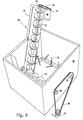
- Fig. 2 depicts a perspective view of the ice bin showing the ice agitator and ice lifting apparatus.
- Fig. 3 depicts a schematic of the control system of the present invention.
- Drink center 10 comprises outer housing 13 which is divided into upper unit 11 and lower unit 12.
- a product source (not shown) is connected to product pumps 14 through 19 via product lines (not shown) to provide product for dispensing.
- the product source is a typical "bag in the box” type, however, any conventional product source container and delivery means could be used.
- lower unit 12 is fitted with motor 20 attached to a water pump (not shown) and carbonator 21.
- Motor 20 is connected to a power source (not shown) via control box 85. Operation of control box 85 will be discussed herein with reference to Fig. 3.
- the input line of the pump is connected to a water source (not shown).
- Output line 23 of the pump is fluidly connected to the water input of carbonator 21.
- the C02 input of carbonator 21 is connected to a C02 source (not shown) via C02 line 24.
- Carbonator 21 is a conventional unit used to introduce C02 into water to develop carbonated water.
- the resultant carbonated water is pumped to cold plate 26 via carbonated water line 25.
- the product pumped from the product source (not shown) by product pumps 14-19 is also transferred to cold plate 26 via product lines 27-32.
- Product pumps 14-19 are provided power from a power source (not shown) via control box 85.
- Cold plate 26 is of any conventional type. Cold plate 26 resides in the bottom of ice bin 33 which is part of lower unit 12. Ice bin 33 resides below ice maker 34 which is housed in upper unit 11. Ice maker 34 is connected to a power source via control box 85 and is of any conventional type. Ice bin 33 holds the ice which is used in the dispensed drinks as well as to provide the cooling for cold plate 26 that is necessary to ensure that the dispensed drinks are below an acceptable dispensing temperature. In addition, cold plate 26 is provided with a drain hole (not shown) connected to a drain (not shown) for draining off water collected in ice bin 33 as a result of melting ice.
- Lower unit 12 is further provided with catch pan 35 connected to a drain (not shown) and used to catch and dispose of excess dispensed product or ice.
- dispensing unit 10 is provided with wheels 36-38 and a fourth (not shown) attached by any conventional means such as a nut and bolt to the underneath of lower unit 12.
- Cold plate 26 is further connected to dispensing/mixing valves 39-44 via product lines 45-50 and carbonated water lines 51-56.
- Dispensing/mixing valves 39-44 are of any conventional type used to mix the product with carbonated water before final dispensing. Dispensing/mixing valves are activated using a membrane switch; however any conventional switch could be used. When one of the membrane switches is pushed, control box 85 delivers power to the selected product pump of product pumps 14-19 and motor 20 to deliver product and carbonated water to that dispensing/mixing valve.
- Upper unit 11 is further provided with ice dispenser 57 which is connected to ice ramp 58 via a chute (not shown) to provide the ice dispensed with the product.
- Ice ramp 58 is powered by motor 59 and descends into ice bin 33 to raise ice up to ice dispenser 57. The functioning of ice dispenser 57 and ice ramp 58 will be discussed herein with reference to Fig. 2.
- upper unit 11 is provided with cup holders 60-63 to provide the dispenser user with a choice in drink size. Additionally, upper unit 11 is provided with lid and straw holder 64 so that all the necessary supplies for a completely dispensed drink are provided.
- Ice dispensing ramp 58 is comprised of an outer shield 70 which houses auger 71 which raises ice up to the chute of ice dispenser 57.
- Motor 59 is connected to shaft sprocket 74 of auger 71 from its sprocket 75 via chain 76.
- Ice dispenser 57 is provided with a membrane switch which activates motor 59 when pushed.
- auger 71 is rotated which causes the ice to be lifted up the flange of auger 71 as they rotate to dump ice out of ice dispenser 57 into a cup held below via the ice chute.
- Motor 59 is connected to a power source (not shown) via control box 85.
- Ice bin 13 is further provided with auger 72 and ice mixer 73 powered by motor 77 which is fixed underneath ice bin 13 and connected to a power source (not shown) via control vox 85.
- motor 77 rotates, 35 auger 72 and ice mixer 73 are rotated via sprockets 78 and 79 through chain 80.
- Auger 72 is provided in ice bin 33 in order to move the ice towards auger 71 so that it can be raised to ice dispenser 57.
- the flanges provided about the shaft of auger 72 push the ice in that direction.
- Ice mixer 73 is provided with a number of rods connected to the shaft of ice mixer 73 by tabs so that the ice is stirred as ice mixer 73 rotates. Ice mixer 73 is provided in bin 33 in order to keep the ice agitated and prevent it from freezing together.
- Control box 85 contains two transformers 86 and, 87, the inputs of which are connected to a conventional 115V power source.
- Transformer 86 is used to provide the current and voltage transformations necessary to operate product pumps 14-19 and motor 20 and on a continual basis to ice maker 34.
- power is delivered to the product pumps and carbonator to dispense a drink.
- Control board 88 is a simple control circuit used to deliver power to motor 59 either when the membrane switch on ice dispenser 57 is activated or on a timed interval basis.
- Control board 88 is constructed of conventional electronics used to supply power to a motor and includes a conventional timing circuit (not shown).
- the timing circuit consists of a first timer which is a programmable self-contained oscillator chip having internal divide circuitry. The output of the first timer input into a second timer which is a standard RC timer chip.
- the two chips used are a 4541 and a 555, respectively, manufactured by any chip manufacturing company such as Motorola or RCA.
- the first timer is used to determine when motor 59 is to be turned on (i.e the activation interval).
- the second timer determines the length of time that motor 59 is activated. Both times are determined by the system user.
- the timing circuit periodically turns on motor 59 to rotate auger 71 so that ice will continually remain in the top flanges of auger 71 even in periods of little use. That is done to keep the time between the pressing of the membrane switch and the actual delivery of the ice to the cup at a minimum.
- the first timer is provided with a reset that is activated when the membrane switch is pushed to reset the first timer because it is not necessary to periodically rotate auger 71 during periods of heavy use.
- Control board 89 is constructed of exactly the same components and functions in a similar manner to control board 88 to deliver power to motor 77. Control board 89 also has a timing circuit which periodically activates motor 77 to rotate auger 72 and ice mixer 73. The only two differences between control board 89 and control board 88 is that control board 89 has different activation intervals, both when and how long, and its first timer is not reset in response to the pushing of the membrane switch on ice dispenser 57.
Landscapes
- Physics & Mathematics (AREA)
- Engineering & Computer Science (AREA)
- General Physics & Mathematics (AREA)
- Mechanical Engineering (AREA)
- Thermal Sciences (AREA)
- General Engineering & Computer Science (AREA)
- Devices For Dispensing Beverages (AREA)
- Organic Low-Molecular-Weight Compounds And Preparation Thereof (AREA)
Abstract
Description
- This invention relates to an apparatus for dispensing both ice and chilled beverages, and more particularly to a complete self-contained drink center capable of furnishing all the drink dispensing needs of any drink server. Available space is a valuable commodity in small convenience stores, cafeterias, concession stands, fast food service lines, and the like. The relevant industry sets certain size and dimensional requirements based on space limitations of service counters and the ease of everyday operation and routine maintenance. The industry is constantly looking for imporved apparatus which take up less counter space while delivering the same or increased levels of efficiency. Small, compact machines facilitating the delivery of food service and suitable for service counters of set and limited dimensions, are constantly in demand. Ice in chilled beverages has become a necessary part of modern day food service, and a combined ice and chilled beverage dispenser, logically increases efficiency in food service delivery by eliminating the need for two separate machines and by making more counter space available.
- One such system is disclosed in WO-A-91/07 346 (US serial No. 07/436 915 of 1989) issued to Schroeder and assigned to the assignee of the present invention.
- That system has the dispensing valves, ice dispenser, and cold plate packaged into a single unit. However, that unit must still be used in combination with additional dispensing apparatus such as a carbonator, dispensing valve pumps, an ice maker, etc. Those additional dispensing apparatus take up valuable counter space which could be used for a different purpose. Furthermore, the Schroeder ice and beverage dispenser and, in fact, many conventional beverage dispenser are not very portable and cannot be used to completely service all the drink dispensing needs of a drink server. Thus, the present invention which is a single self-contained drink center having all the necessary elements so that only a product source need be connected to begin serving drinks has been designed.
- Additionally, of particular interest in the drink dispensing industry is the reduction of operating costs for existing or new markets. For example, any person desiring to open a food service establishment will be extremely concerned about space, especially with the high rent prices of presently available commercial property. Also, any current food and drink server wishing to expand will encounter the same concerns. Furthermore, with the advent of the European common market, an entirely new customer has been created. Presently, the European food service industry typically dispenses its soda products in bottles; consequently no counter space is available for drink dispensing equipment. The complete drink center of the present invention will allow drinks to be dispensed in an easy, cost effective and inexpensive manner in such establishments without expensive remodeling. Another industry where the present invention will be used is convenience stores. Recently, many existing convenience stores have added food products such as microwavable sandwiches and pizza. To complement such products drinks must also be served. However, counter space for conventional drink dispensers is unavailable.
- Therefore, it is an object of the present invention to provide a portable single complete drink center that is compact and will service all the drink dispensing needs of a drink server.
- The present invention as defined in
claim 1 provides a significant improvement over conventional drink dispensing apparatus because its compact size makes it nearly half as large. The present invention allows drinks to be served from a single complete drink center. The complete drink center is portable and may be positioned in any available space about a restaurant or cafe. Once positioned, the drink center is connected to a product source and is then ready to dispense drinks. A person wishing to receive a drink merely takes a cup from one of the cup holders and fills it with ice and dispenses the desired drink. Afterward, a lid and straw can be retrieved from an additional holder on the dispensing unit. - To provide the complete drink center, the present invention is fitted with an ice maker residing above an ice storate bin which has a cold plate resting in the bottom. The ice maker provides the ice necessary to supply both the ice required in the drinks as well as providing the cooling necessary for the cold plate. Situated between the product source and the cold plate are the pumps necessary to provide the pressure to dispense the product. Additionally, a water pump and carbonator are positioned between a water source and the cold plate to provide the carbonated water necessary when mixing the drinks. The product source, water source, water pump, carbonator, product pumps, cold plate, and dispensing valves are fluidly connected by product lines.
- The present invention is of a size and configuration such that it takes up less space than any other conventional dispensing unit while providing all the required dispensing needs of a drink server in a portable single complete unit.
- Other objects, features, and advantages of this invention will become evident in light of the following description of the invention.
- Fig. 1 depicts a perspective view of the complete drink center of the present invention with a cut-away perspective view into the interior, showing the internal components contained in the preferred embodiment of the complete drink center.
- Fig. 2 depicts a perspective view of the ice bin showing the ice agitator and ice lifting apparatus.
- Fig. 3 depicts a schematic of the control system of the present invention.
- Referring to Fig. 1, the complete drink center of the preferred embodiment of the present invention will be disclosed.
Drink center 10 comprisesouter housing 13 which is divided intoupper unit 11 andlower unit 12. A product source (not shown) is connected toproduct pumps 14 through 19 via product lines (not shown) to provide product for dispensing. The product source is a typical "bag in the box" type, however, any conventional product source container and delivery means could be used. - Additionally,
lower unit 12 is fitted withmotor 20 attached to a water pump (not shown) andcarbonator 21.Motor 20 is connected to a power source (not shown) viacontrol box 85. Operation ofcontrol box 85 will be discussed herein with reference to Fig. 3. The input line of the pump is connected to a water source (not shown).Output line 23 of the pump is fluidly connected to the water input ofcarbonator 21. The C02 input ofcarbonator 21 is connected to a C02 source (not shown) viaC02 line 24.Carbonator 21 is a conventional unit used to introduce C02 into water to develop carbonated water. The resultant carbonated water is pumped tocold plate 26 viacarbonated water line 25. The product pumped from the product source (not shown) by product pumps 14-19 is also transferred tocold plate 26 via product lines 27-32. Product pumps 14-19 are provided power from a power source (not shown) viacontrol box 85. -
Cold plate 26 is of any conventional type. Coldplate 26 resides in the bottom ofice bin 33 which is part oflower unit 12. Ice bin 33 resides belowice maker 34 which is housed inupper unit 11. Icemaker 34 is connected to a power source viacontrol box 85 and is of any conventional type. Ice bin 33 holds the ice which is used in the dispensed drinks as well as to provide the cooling forcold plate 26 that is necessary to ensure that the dispensed drinks are below an acceptable dispensing temperature. In addition,cold plate 26 is provided with a drain hole (not shown) connected to a drain (not shown) for draining off water collected inice bin 33 as a result of melting ice. -
Lower unit 12 is further provided withcatch pan 35 connected to a drain (not shown) and used to catch and dispose of excess dispensed product or ice. To provide portability, dispensingunit 10 is provided with wheels 36-38 and a fourth (not shown) attached by any conventional means such as a nut and bolt to the underneath oflower unit 12. -
Cold plate 26 is further connected to dispensing/mixing valves 39-44 via product lines 45-50 and carbonated water lines 51-56. Dispensing/mixing valves 39-44 are of any conventional type used to mix the product with carbonated water before final dispensing. Dispensing/mixing valves are activated using a membrane switch; however any conventional switch could be used. When one of the membrane switches is pushed,control box 85 delivers power to the selected product pump of product pumps 14-19 andmotor 20 to deliver product and carbonated water to that dispensing/mixing valve. -
Upper unit 11 is further provided withice dispenser 57 which is connected toice ramp 58 via a chute (not shown) to provide the ice dispensed with the product.Ice ramp 58 is powered bymotor 59 and descends intoice bin 33 to raise ice up toice dispenser 57. The functioning ofice dispenser 57 andice ramp 58 will be discussed herein with reference to Fig. 2. - To provide a complete dispensing unit,
upper unit 11 is provided with cup holders 60-63 to provide the dispenser user with a choice in drink size. Additionally,upper unit 11 is provided with lid andstraw holder 64 so that all the necessary supplies for a completely dispensed drink are provided. - Referring to Fig. 2, the operation of
ice dispenser 57 andice ramp 58 will be disclosed. Ice dispensingramp 58 is comprised of anouter shield 70 which houses auger 71 which raises ice up to the chute ofice dispenser 57.Motor 59 is connected toshaft sprocket 74 ofauger 71 from itssprocket 75 viachain 76.Ice dispenser 57 is provided with a membrane switch which activatesmotor 59 when pushed. Asmotor 59 rotates,auger 71 is rotated which causes the ice to be lifted up the flange ofauger 71 as they rotate to dump ice out ofice dispenser 57 into a cup held below via the ice chute.Motor 59 is connected to a power source (not shown) viacontrol box 85. -
Ice bin 13 is further provided withauger 72 andice mixer 73 powered bymotor 77 which is fixed underneathice bin 13 and connected to a power source (not shown) viacontrol vox 85. Asmotor 77 rotates, 35auger 72 andice mixer 73 are rotated viasprockets chain 80.Auger 72 is provided inice bin 33 in order to move the ice towardsauger 71 so that it can be raised toice dispenser 57. The flanges provided about the shaft ofauger 72 push the ice in that direction.Ice mixer 73 is provided with a number of rods connected to the shaft ofice mixer 73 by tabs so that the ice is stirred asice mixer 73 rotates.Ice mixer 73 is provided inbin 33 in order to keep the ice agitated and prevent it from freezing together. - Referring to Fig. 3, the operation of
control box 85 will be disclosed.Control box 85 contains twotransformers Transformer 86 is used to provide the current and voltage transformations necessary to operate product pumps 14-19 andmotor 20 and on a continual basis toice maker 34. For actual drink dispensing, when any one of dispensing/mixing valves 39-44 is activated, power is delivered to the product pumps and carbonator to dispense a drink. -
Transformer 87 merely provides the current and voltage transformations required to operatemotors Control board 88 is a simple control circuit used to deliver power tomotor 59 either when the membrane switch onice dispenser 57 is activated or on a timed interval basis.Control board 88 is constructed of conventional electronics used to supply power to a motor and includes a conventional timing circuit (not shown). The timing circuit consists of a first timer which is a programmable self-contained oscillator chip having internal divide circuitry. The output of the first timer input into a second timer which is a standard RC timer chip. In the preferred embodiment, the two chips used are a 4541 and a 555, respectively, manufactured by any chip manufacturing company such as Motorola or RCA. The first timer is used to determine whenmotor 59 is to be turned on (i.e the activation interval). The second timer determines the length of time that motor 59 is activated. Both times are determined by the system user. The timing circuit periodically turns onmotor 59 to rotateauger 71 so that ice will continually remain in the top flanges ofauger 71 even in periods of little use. That is done to keep the time between the pressing of the membrane switch and the actual delivery of the ice to the cup at a minimum. Additionally, the first timer is provided with a reset that is activated when the membrane switch is pushed to reset the first timer because it is not necessary to periodically rotateauger 71 during periods of heavy use. -
Control board 89 is constructed of exactly the same components and functions in a similar manner to controlboard 88 to deliver power tomotor 77.Control board 89 also has a timing circuit which periodically activatesmotor 77 to rotateauger 72 andice mixer 73. The only two differences betweencontrol board 89 andcontrol board 88 is thatcontrol board 89 has different activation intervals, both when and how long, and its first timer is not reset in response to the pushing of the membrane switch onice dispenser 57. - While the preferred embodiment of the present invention has been described for the purposes of this disclosure, changes in the design and arrangements can made by those skilled in the art, which changes are encompassed within the invention as defined by the appended claims.
Claims (8)
- A portable complete self-contained post-mix drink center for dispensing a product comprising:an outer housing (13);means for pumping (14-19) product fluidly connected to and positioned between a product source and a means for cooling (26), said means for cooling housed within a means (33) for storing ice;means (21) for carbonating water fluidly connected to and positioned between a water source, a CO₂ source, and said means for cooling (26);means (34) for making ice in communication with said means for storing ice (33);drink dispensing means (39-44) for dispensing said product and said carbonated water fluidly connected to said means for cooling;means for dispensing ice (57) in communication with said ice storage means, wherein said means for dispensing ice comprises:a first auger (71) housed within an enclosure (70) for transporting ice from said means for storing ice to an ice dispensing chute, said first auger rotatably connected to a first motor (59) wherein ice is transported through said enclosure by said first auger as said first auger rotates,a second auger (72) rotatably connected to a second motor (77) wherein ice is pushed by said second auger to an opening in said enclosure as said second auger rotates,an ice mixer (73) rotatably connected to said second motor (77) for agitating the ice to keep it from freezing together; andcontrol means (85) operably connected between a power source and said product pumping means, said means for carbonating water, said ice making means, and said ice dispensing means to control the delivery of power to said means, wherein said control means comprises:a switch means to allow the manual activation of said first motor to rotate said first auger and facilitate the dispensing of ice, anda first timing means for periodically turning on and off said first motor to rotate said first auger, thereby ensuring ice remains in the flanges of said first auger nearest said ice dispensing chute.
- The drink dispensing center according to claim 1 wherein said means for cooling comprises a cold plate (26).
- The drink dispensing center according to claim 1 wherein said ice storage means comprises an ice storage bin (33).
- The drink dispensing center according to claim 1 wherein said means for carbonating water comprises:a water pump fluidly connected between said water source and a carbonator; andsaid carbonator further being connected between said CO₂ source and said cold plate.
- The drink dispensing center according to claim 1 further comprising means (64) for holding drink cups, lids, and straws connected to said outer housing.
- The drink dispensing center according to claim 1, wherein said control means further comprises a second timing means for periodically turning on and off said second motor to rotate said second auger and said ice mixer.
- The drink dispensing center according to claim 6, wherein said control means further comprises:a first transformer (86) operably connected between said power source and said product pumping means, said ice making means, and said means for carbonating water for transforming the power delivered from said power source; anda second transformer (87) operably connected between said power source and said first timing means and said second timing means for transforming the power delivered from said power source.
- The drink dispensing center according to claim 1, wherein said first timing means comprises a reset means which resets said first timing means in response to the activation of said switch means.
Applications Claiming Priority (3)
| Application Number | Priority Date | Filing Date | Title |
|---|---|---|---|
| US735376 | 1991-07-24 | ||
| US07/735,376 US5230448A (en) | 1991-07-24 | 1991-07-24 | Complete system self-contained drink and ice dispensing |
| PCT/US1992/005638 WO1993002011A1 (en) | 1991-07-24 | 1992-07-06 | Complete soda system |
Publications (3)
| Publication Number | Publication Date |
|---|---|
| EP0595869A1 EP0595869A1 (en) | 1994-05-11 |
| EP0595869A4 EP0595869A4 (en) | 1995-06-21 |
| EP0595869B1 true EP0595869B1 (en) | 1996-05-22 |
Family
ID=24955508
Family Applications (1)
| Application Number | Title | Priority Date | Filing Date |
|---|---|---|---|
| EP92915242A Expired - Lifetime EP0595869B1 (en) | 1991-07-24 | 1992-07-06 | Complete soda system |
Country Status (9)
| Country | Link |
|---|---|
| US (1) | US5230448A (en) |
| EP (1) | EP0595869B1 (en) |
| JP (1) | JP2554838B2 (en) |
| AU (1) | AU652854B2 (en) |
| CA (1) | CA2113994C (en) |
| DE (1) | DE69211003T2 (en) |
| ES (1) | ES2089540T3 (en) |
| GR (1) | GR3020829T3 (en) |
| WO (1) | WO1993002011A1 (en) |
Families Citing this family (41)
| Publication number | Priority date | Publication date | Assignee | Title |
|---|---|---|---|---|
| US5273219A (en) * | 1993-01-11 | 1993-12-28 | White Consolidated Industries, Inc. | Ice dispenser |
| US5542573A (en) * | 1994-06-10 | 1996-08-06 | Follett Corporation | Under-counter ice storage apparatus for dispensing ice-dual sided |
| US5715700A (en) * | 1995-06-05 | 1998-02-10 | The Coca-Cola Company | Round drink dispenser |
| GB2303354B (en) * | 1995-07-15 | 1999-03-24 | Coca Cola & Schweppes Beverage | Drinks-dispensing apparatus |
| US5664436A (en) * | 1996-04-29 | 1997-09-09 | Lancer Corporation | Component configuration for enhancing dispenser serviceability |
| US5692392A (en) * | 1996-08-26 | 1997-12-02 | Swier; Raymond R. | Soft frozen beverage dispenser apparatus and method |
| JPH10253209A (en) * | 1997-03-12 | 1998-09-25 | Sanyo Electric Co Ltd | Beverage supplying and ice making device |
| US6039220A (en) * | 1997-07-10 | 2000-03-21 | Imi Cornelius Inc. | Low profile ice dispenser |
| US5987900A (en) * | 1998-05-06 | 1999-11-23 | Maximicer, Llc | Method and system for prechilling ambient waters for beverage dispensing machines and ice machines |
| US6224297B1 (en) * | 1998-05-14 | 2001-05-01 | Tmo Enterprises Limited | Method and apparatus for use in conveying material |
| US6705107B2 (en) * | 1998-10-06 | 2004-03-16 | Manitowoc Foodservice Companies, Inc. | Compact ice making machine with cool vapor defrost |
| JP4293652B2 (en) | 1998-10-21 | 2009-07-08 | ホシザキ電機株式会社 | Ice dispenser |
| BR0010743A (en) * | 1999-05-20 | 2002-04-16 | Lancer Partnership Ltd | Beverage Dispenser, processes for designing a beverage dispenser or reconfiguring an existing beverage dispenser, to receive user input into a beverage dispenser, to send information from a beverage dispenser to a user, to dispense a beverage from a beverage dispenser, external communication for a beverage dispenser, and external communication for a beverage dispenser, system for monitoring frozen refrigerant, process for controlling a refrigeration unit of a beverage dispenser, system for level monitoring liquid, and, process to control a carbonation system of a drink dispenser |
| US6218241B1 (en) * | 2000-03-28 | 2001-04-17 | United Microelectronics Corp. | Fabrication method for a compact DRAM cell |
| US6439428B1 (en) * | 2000-08-03 | 2002-08-27 | Lancer Partnership L.L.P. | Dispenser with features for enhanced maintainability |
| US6637227B2 (en) * | 2000-09-15 | 2003-10-28 | Mile High Equipment Co. | Quiet ice making apparatus |
| US7017353B2 (en) * | 2000-09-15 | 2006-03-28 | Scotsman Ice Systems | Integrated ice and beverage dispenser |
| EP1436226A4 (en) * | 2001-09-06 | 2008-07-16 | Manitowoc Foodservice Co Inc | Low volume beverage dispenser |
| WO2003035536A2 (en) * | 2001-10-19 | 2003-05-01 | Manitowoc Foodservice Companies, Inc. | Beverage dispenser with integral ice maker |
| US6622506B2 (en) * | 2002-02-13 | 2003-09-23 | William T. Sanders | Transportable ice maker |
| US6880358B2 (en) * | 2002-03-16 | 2005-04-19 | Manitowoc Foodservice Companies, Inc. | Ice and ice/beverage dispensers |
| WO2005035430A2 (en) * | 2003-09-11 | 2005-04-21 | Scotsman Ice Systems | Beverage dispensing system |
| US6945070B1 (en) * | 2004-04-15 | 2005-09-20 | Imi Cornelius Inc. | Ice cooled cold plate and carbonator |
| US8353177B2 (en) * | 2004-09-27 | 2013-01-15 | Whirlpool Corporation | Apparatus and method for dispensing ice from a bottom mount refrigerator |
| US7266951B2 (en) * | 2004-10-26 | 2007-09-11 | Whirlpool Corporation | Ice making and dispensing system |
| US7681408B2 (en) * | 2005-12-07 | 2010-03-23 | Paper Making Controls Service, Inc. | Automated ice vending machine and method of vending ice |
| KR20090006510A (en) * | 2007-07-12 | 2009-01-15 | 엘지전자 주식회사 | Ice Maker Assembly for Refrigerator |
| US8365956B2 (en) * | 2008-05-27 | 2013-02-05 | Lancer Corporation | Method and apparatus for a beverage dispenser |
| US8459176B2 (en) * | 2008-12-08 | 2013-06-11 | Enodis Corporation | Integrated method and system for dispensing and blending/mixing beverage ingredients |
| US20110023505A1 (en) * | 2009-06-24 | 2011-02-03 | Nikolay Popov | Refrigeration systems for blended iced beverage machines |
| US8746296B2 (en) | 2012-05-22 | 2014-06-10 | General Electric Company | Refrigerator appliance with features for assisted dispensing |
| US9066529B2 (en) | 2011-04-27 | 2015-06-30 | Brooklyn Water Enterprises, Llc | Method and apparatus for flavored ice making |
| US9227830B2 (en) | 2012-02-27 | 2016-01-05 | The Coca-Cola Company | Automated beverage dispensing system with ice and beverage dispensing |
| MX349454B (en) | 2012-02-27 | 2017-07-31 | Coca Cola Co | Automated beverage dispensing system with cup lidding and beverage identification. |
| US20130277394A1 (en) * | 2012-04-18 | 2013-10-24 | Schroeder Industries, Inc. D/B/A Schroeder America | Moveable roll around self-contained ice cooled beverage dispensing apparatus |
| USD770214S1 (en) | 2015-05-19 | 2016-11-01 | Bunn-O-Matic Corporation | Beverage dispenser |
| JP2019167137A (en) * | 2018-03-23 | 2019-10-03 | アサヒビール株式会社 | Liquid quality control device and method |
| JP7154609B2 (en) | 2019-12-27 | 2022-10-18 | 株式会社コナミデジタルエンタテインメント | GAME VIEWING SYSTEM, COMPUTER PROGRAM FOR GAME VIEWING SYSTEM, AND GAME VIEWING SYSTEM CONTROL METHOD |
| US12031767B2 (en) * | 2021-01-11 | 2024-07-09 | Haier Us Appliance Solutions, Inc. | Free-standing ice or beverage dispensing appliance |
| US12612296B2 (en) * | 2023-02-07 | 2026-04-28 | Marmon Foodservice Technologies, Inc. | Cold plate prechill circuit |
| EP4688641A1 (en) * | 2023-03-24 | 2026-02-11 | Rbar, Llc | Devices, systems, and methods for generating customized beverages |
Family Cites Families (13)
| Publication number | Priority date | Publication date | Assignee | Title |
|---|---|---|---|---|
| US3215312A (en) * | 1963-06-12 | 1965-11-02 | Universal Match Corp | Dispenser of soft drinks of high or low carbonation |
| US3858765A (en) * | 1973-05-18 | 1975-01-07 | Servend Distributors | Dispensing apparatus |
| US3949902A (en) * | 1973-06-11 | 1976-04-13 | Thompson Frank B | Portable dispensing bar |
| US4319698A (en) * | 1979-08-30 | 1982-03-16 | Kubota Ltd. | Automatic cup drink vending machine |
| US4687120A (en) * | 1982-12-27 | 1987-08-18 | The Cornelius Company | Method and apparatus for dispensing cold beverage |
| US4592490A (en) * | 1984-02-24 | 1986-06-03 | The Coca-Cola Company | Beverage dispenser system convertable between gravity and pressure |
| JPS63143476A (en) * | 1986-12-08 | 1988-06-15 | ホシザキ電機株式会社 | Ice dispenser |
| CA1307242C (en) * | 1986-12-18 | 1992-09-08 | John R. Bradbury | Apparatus and method for storing and dispensing particulate ice |
| US4951719A (en) * | 1989-02-27 | 1990-08-28 | The Coca-Cola Company | Automatic postmix beverage dispensing system with flavor indicators |
| US5058630A (en) | 1989-02-27 | 1991-10-22 | The Coca-Cola Company | Automatic beverage dispensing system with programmable cup drop |
| US5054654A (en) * | 1989-11-14 | 1991-10-08 | Schroeder Alfred A | Combination ice and chilled beverage dispenser |
| US5104007A (en) * | 1990-03-29 | 1992-04-14 | Scotsman Group, Inc. | Ice and beverage dispensing apparatus |
| JP6342317B2 (en) | 2014-12-12 | 2018-06-13 | 株式会社日立産機システム | Motor control device |
-
1991
- 1991-07-24 US US07/735,376 patent/US5230448A/en not_active Expired - Lifetime
-
1992
- 1992-07-06 AU AU23182/92A patent/AU652854B2/en not_active Ceased
- 1992-07-06 WO PCT/US1992/005638 patent/WO1993002011A1/en not_active Ceased
- 1992-07-06 EP EP92915242A patent/EP0595869B1/en not_active Expired - Lifetime
- 1992-07-06 ES ES92915242T patent/ES2089540T3/en not_active Expired - Lifetime
- 1992-07-06 JP JP5502827A patent/JP2554838B2/en not_active Expired - Fee Related
- 1992-07-06 DE DE69211003T patent/DE69211003T2/en not_active Expired - Fee Related
- 1992-07-06 CA CA002113994A patent/CA2113994C/en not_active Expired - Fee Related
-
1996
- 1996-08-19 GR GR960402193T patent/GR3020829T3/en unknown
Also Published As
| Publication number | Publication date |
|---|---|
| US5230448A (en) | 1993-07-27 |
| EP0595869A4 (en) | 1995-06-21 |
| DE69211003D1 (en) | 1996-06-27 |
| GR3020829T3 (en) | 1996-11-30 |
| CA2113994C (en) | 1998-06-23 |
| WO1993002011A1 (en) | 1993-02-04 |
| JPH06511217A (en) | 1994-12-15 |
| AU652854B2 (en) | 1994-09-08 |
| CA2113994A1 (en) | 1993-02-04 |
| DE69211003T2 (en) | 1996-12-19 |
| EP0595869A1 (en) | 1994-05-11 |
| ES2089540T3 (en) | 1996-10-01 |
| JP2554838B2 (en) | 1996-11-20 |
| AU2318292A (en) | 1993-02-23 |
Similar Documents
| Publication | Publication Date | Title |
|---|---|---|
| US5230448A (en) | Complete system self-contained drink and ice dispensing | |
| CA2146114C (en) | Ice dispenser with an ice flow regulator | |
| US5054654A (en) | Combination ice and chilled beverage dispenser | |
| US9346659B2 (en) | Hybrid beverage dispenser | |
| US5692392A (en) | Soft frozen beverage dispenser apparatus and method | |
| CN101553128A (en) | Vending apparatus for dispensing beverages containing fruits or vegetables | |
| US20090095771A1 (en) | Beverage base dispenser and method | |
| US6267496B1 (en) | Beverage supply apparatus for dispensing machine | |
| US20220101680A1 (en) | Vending machine for natural fruit juices prepared on the spot | |
| US3378170A (en) | Mixed beverage refrigerating and dispensing machine | |
| US3343726A (en) | Beverage mixer and dispenser | |
| JP2936107B2 (en) | Post-mix beverage dispenser for box storage high viscosity beverage bags | |
| GB2146621A (en) | Post-mix carbonated beverage dispenser | |
| WO2005080199A1 (en) | Automatic consumer-operated dispensing machine | |
| US6543646B2 (en) | Method and apparatus for remotely dispensing beverages | |
| CN116671783A (en) | Automated auxiliary device and method for ready-made beverages | |
| RU2772182C2 (en) | Beverage dispensing system | |
| JP2001256548A (en) | Beverage vending machine | |
| JP2000357270A (en) | Beverage dispenser device |
Legal Events
| Date | Code | Title | Description |
|---|---|---|---|
| PUAI | Public reference made under article 153(3) epc to a published international application that has entered the european phase |
Free format text: ORIGINAL CODE: 0009012 |
|
| 17P | Request for examination filed |
Effective date: 19940216 |
|
| AK | Designated contracting states |
Kind code of ref document: A1 Designated state(s): DE ES FR GB GR IT |
|
| A4 | Supplementary search report drawn up and despatched | ||
| AK | Designated contracting states |
Kind code of ref document: A4 Designated state(s): DE ES FR GB GR IT |
|
| 17Q | First examination report despatched |
Effective date: 19950809 |
|
| GRAH | Despatch of communication of intention to grant a patent |
Free format text: ORIGINAL CODE: EPIDOS IGRA |
|
| GRAA | (expected) grant |
Free format text: ORIGINAL CODE: 0009210 |
|
| AK | Designated contracting states |
Kind code of ref document: B1 Designated state(s): DE ES FR GB GR IT |
|
| REF | Corresponds to: |
Ref document number: 69211003 Country of ref document: DE Date of ref document: 19960627 |
|
| ET | Fr: translation filed | ||
| ITF | It: translation for a ep patent filed | ||
| REG | Reference to a national code |
Ref country code: ES Ref legal event code: FG2A Ref document number: 2089540 Country of ref document: ES Kind code of ref document: T3 |
|
| REG | Reference to a national code |
Ref country code: GR Ref legal event code: FG4A Free format text: 3020829 |
|
| REG | Reference to a national code |
Ref country code: ES Ref legal event code: FG2A Ref document number: 2089540 Country of ref document: ES Kind code of ref document: T3 |
|
| PLBE | No opposition filed within time limit |
Free format text: ORIGINAL CODE: 0009261 |
|
| STAA | Information on the status of an ep patent application or granted ep patent |
Free format text: STATUS: NO OPPOSITION FILED WITHIN TIME LIMIT |
|
| 26N | No opposition filed | ||
| PGFP | Annual fee paid to national office [announced via postgrant information from national office to epo] |
Ref country code: GB Payment date: 20010711 Year of fee payment: 10 |
|
| PGFP | Annual fee paid to national office [announced via postgrant information from national office to epo] |
Ref country code: FR Payment date: 20010712 Year of fee payment: 10 |
|
| PGFP | Annual fee paid to national office [announced via postgrant information from national office to epo] |
Ref country code: DE Payment date: 20010716 Year of fee payment: 10 |
|
| PGFP | Annual fee paid to national office [announced via postgrant information from national office to epo] |
Ref country code: GR Payment date: 20010731 Year of fee payment: 10 |
|
| PGFP | Annual fee paid to national office [announced via postgrant information from national office to epo] |
Ref country code: ES Payment date: 20010822 Year of fee payment: 10 |
|
| REG | Reference to a national code |
Ref country code: GB Ref legal event code: IF02 |
|
| PG25 | Lapsed in a contracting state [announced via postgrant information from national office to epo] |
Ref country code: GB Free format text: LAPSE BECAUSE OF NON-PAYMENT OF DUE FEES Effective date: 20020706 |
|
| PG25 | Lapsed in a contracting state [announced via postgrant information from national office to epo] |
Ref country code: ES Free format text: LAPSE BECAUSE OF NON-PAYMENT OF DUE FEES Effective date: 20020707 |
|
| PG25 | Lapsed in a contracting state [announced via postgrant information from national office to epo] |
Ref country code: DE Free format text: LAPSE BECAUSE OF NON-PAYMENT OF DUE FEES Effective date: 20030201 |
|
| PG25 | Lapsed in a contracting state [announced via postgrant information from national office to epo] |
Ref country code: GR Free format text: LAPSE BECAUSE OF NON-PAYMENT OF DUE FEES Effective date: 20030206 |
|
| GBPC | Gb: european patent ceased through non-payment of renewal fee |
Effective date: 20020706 |
|
| PG25 | Lapsed in a contracting state [announced via postgrant information from national office to epo] |
Ref country code: FR Free format text: LAPSE BECAUSE OF NON-PAYMENT OF DUE FEES Effective date: 20030331 |
|
| REG | Reference to a national code |
Ref country code: FR Ref legal event code: ST |
|
| REG | Reference to a national code |
Ref country code: ES Ref legal event code: FD2A Effective date: 20030811 |
|
| PG25 | Lapsed in a contracting state [announced via postgrant information from national office to epo] |
Ref country code: IT Free format text: LAPSE BECAUSE OF NON-PAYMENT OF DUE FEES;WARNING: LAPSES OF ITALIAN PATENTS WITH EFFECTIVE DATE BEFORE 2007 MAY HAVE OCCURRED AT ANY TIME BEFORE 2007. THE CORRECT EFFECTIVE DATE MAY BE DIFFERENT FROM THE ONE RECORDED. Effective date: 20050706 |