EP0595779B1 - Dispensing nozzle - Google Patents
Dispensing nozzle Download PDFInfo
- Publication number
- EP0595779B1 EP0595779B1 EP19930850154 EP93850154A EP0595779B1 EP 0595779 B1 EP0595779 B1 EP 0595779B1 EP 19930850154 EP19930850154 EP 19930850154 EP 93850154 A EP93850154 A EP 93850154A EP 0595779 B1 EP0595779 B1 EP 0595779B1
- Authority
- EP
- European Patent Office
- Prior art keywords
- base
- nozzle
- dispenser
- towels
- exit aperture
- Prior art date
- Legal status (The legal status is an assumption and is not a legal conclusion. Google has not performed a legal analysis and makes no representation as to the accuracy of the status listed.)
- Expired - Lifetime
Links
Images

Classifications
-
- A—HUMAN NECESSITIES
- A47—FURNITURE; DOMESTIC ARTICLES OR APPLIANCES; COFFEE MILLS; SPICE MILLS; SUCTION CLEANERS IN GENERAL
- A47K—SANITARY EQUIPMENT; ACCESSORIES THEREFOR, e.g. TOILET ACCESSORIES
- A47K10/00—Body-drying implements; Toilet paper; Holders therefor
- A47K10/24—Towel dispensers; Toilet paper dispensers
- A47K10/32—Dispensers for paper towels or toilet paper
- A47K10/34—Dispensers for paper towels or toilet paper dispensing from a web, e.g. with mechanical dispensing means
- A47K10/38—Dispensers for paper towels or toilet paper dispensing from a web, e.g. with mechanical dispensing means the web being rolled-up
- A47K10/3809—Dispensers for paper towels or toilet paper dispensing from a web, e.g. with mechanical dispensing means the web being rolled-up with roll spindles which are not directly supported
- A47K10/3818—Dispensers for paper towels or toilet paper dispensing from a web, e.g. with mechanical dispensing means the web being rolled-up with roll spindles which are not directly supported with a distribution opening which is perpendicular to the rotation axis
-
- B—PERFORMING OPERATIONS; TRANSPORTING
- B65—CONVEYING; PACKING; STORING; HANDLING THIN OR FILAMENTARY MATERIAL
- B65D—CONTAINERS FOR STORAGE OR TRANSPORT OF ARTICLES OR MATERIALS, e.g. BAGS, BARRELS, BOTTLES, BOXES, CANS, CARTONS, CRATES, DRUMS, JARS, TANKS, HOPPERS, FORWARDING CONTAINERS; ACCESSORIES, CLOSURES, OR FITTINGS THEREFOR; PACKAGING ELEMENTS; PACKAGES
- B65D83/00—Containers or packages with special means for dispensing contents
- B65D83/08—Containers or packages with special means for dispensing contents for dispensing thin flat articles in succession
- B65D83/0805—Containers or packages with special means for dispensing contents for dispensing thin flat articles in succession through an aperture in a wall
-
- Y—GENERAL TAGGING OF NEW TECHNOLOGICAL DEVELOPMENTS; GENERAL TAGGING OF CROSS-SECTIONAL TECHNOLOGIES SPANNING OVER SEVERAL SECTIONS OF THE IPC; TECHNICAL SUBJECTS COVERED BY FORMER USPC CROSS-REFERENCE ART COLLECTIONS [XRACs] AND DIGESTS
- Y10—TECHNICAL SUBJECTS COVERED BY FORMER USPC
- Y10T—TECHNICAL SUBJECTS COVERED BY FORMER US CLASSIFICATION
- Y10T225/00—Severing by tearing or breaking
- Y10T225/30—Breaking or tearing apparatus
- Y10T225/393—Web restrainer
Definitions
- the present invention relates to a dispensing nozzle for a towel dispenser, the nozzle being adjustable so as to accommodate towels of different thicknesses.
- Paper towels have many uses and are commonly used or cleaning and drying various surfaces. Typically, the towels will come from the manufacturer in a rolled or folded configuration, with or without perforations. Whether the towels are in a perforated format or nonperforated format, the tearing of the towels is not precise, resulting in unnecessary discard of partially torn towels or the extra towels used. Thus, it has become common practice for towel dispensers to contain sharp or tensioned edges to ease the user in the tearing process.
- US-A-4,905,868 forming the basis for the preamble of the independent claim, discloses a dispenser nozzle, along with an exit aperture, for a paper towel dispenser for accurately and reliably dispensing individual towels from a continuous web of towels.
- the nozzle has a conical shape for passing the paper towels therethrough, and causing each paper towel to be compressed as it moves through the nozzle.
- the friction between the paper towel and the inside of the nozzle eventually causes the dispensed paper towel to be separated from the web of towels.
- the diameter of the exit aperture of the nozzle may be enlarged in order to accommodate thicker paper towels.
- an operator removes the tip of the nozzle by cutting, clipping or breaking. Once the operator enlarges the exit aperture, the same nozzle cannot be narrowed to accommodate a thinner towel. Thus, to narrow the exit aperture of the nozzle, the operator must replace the old nozzle portion with a new nozzle portion.
- patented towel dispensers include: US-A-4,648,530 disclosing a dispenser for perforated precut folded or rolled towels and, US-A-4,387,832 disclosing a dispenser for pre-moistened perforated towels.
- An adjustable nozzle for a dispenser is known from GB-A-677 336.
- This prior art nozzle is provided on a bottle or a collapsible tube and can be used to regulate the flow of liquid therefrom.
- a development of the disclosed nozzle could be used with a towel dispenser.
- the known nozzle also has the disadvantage that there is no provision for ensuring that the aperture size set by the fixture is maintained during subsequent use of the dispenser. This is important for a towel dispenser where the set aperture size should remain unchanged until the dispenser is to be used with towels of different thickness.
- an adjustable nozzle which can be adjusted to enlarge or decrease the size of the exit aperture for dispensing the towel, with means for maintaining the aperture at the adjusted size during subsequent use.
- Paper towels are dispensed from a number of different types of containers. Some containers are designed for dispensing precut or z-folded towels. Other containers are designed for dispensing towels, wherein the dispensed towels are pulled from either the inside or outside of a roll.
- the disclosed invention may have broad applicability, it relates primarily to a nozzle for a dispenser adapted to dispense towels from the inside of a continuous roll.
- the dispenser may include a box-like structure, comprised of either metal or a plastic material, having an aperture in the center of the bottom thereof. A nozzle is fitted within the aperture in order to facilitate separating the towel from the web of towels in the dispenser, and furthermore to facilitate removal of the towels from the dispenser.
- Fig. 1 illustrates a novel adjustable nozzle 10 for such a towel dispenser.
- the dispenser nozzle 10 includes a base 20 having a conical portion 21 therein.
- the conical portion 21 defines a channel 15 through which towels (not shown) are pulled as they are dispensed. Additionally, the conical portion 21 has a narrow end 23 defining an aperture 6b. The towels exit the dispenser nozzle 10 through the channel 15 and the aperture 6b.
- the conical portion 21 of the base 20 includes a plurality of extensions 8 that are defined and separated by substantially parallel slits 9. These slits 9 impart an elastic characteristic to the conical portion 21. Furthermore, the conical portion 21 has a bottom edge 7b upon which the towels may be torn as they are dispensed from the dispenser nozzle 10.
- the base 20 further includes an outer wall 30 for engaging the towel dispenser.
- the outer wall 30 includes a curved bottom 31 at one edge thereof.
- the outer wall 30 includes a rim 32A from which extend a plurality of tabs 32B for securing the base 20 to the towel dispenser.
- the rim 32A extends perpendicularly from the outer wall 30, and the tabs 32B are parallel to and extend outwardly from the rim 32A.
- the towel dispenser includes an outer wall 3 having a surface 4.
- the surface 4 includes a plurality of platforms 4A.
- the platforms 4A engage with the tabs 32B of the nozzle 10.
- the rim 32A remains outside of the towel dispenser.
- the tabs 32B of the outer wall 30 provide a contact between the towel dispenser and the dispenser nozzle 10.
- the curved bottom 31 of the base 20 is used as a gripping surface when replacing the dispenser nozzle 10.
- the dispenser nozzle 10 may be replaced by rotating the nozzle 10 so that the tabs 32B are free from the platforms 4A, and then pulling the dispenser nozzle 10 in a direction away from the towel dispenser.
- the base 20 of the dispenser nozzle 10 may be comprised of an elastomeric material.
- the material is a hard rubber known as ABS.
- the base may be made from another material having a similar quality and characteristic. Due to the combination of the plurality of slits 9, the extensions 8 and the elasticity provided by the ABS, narrowing and expanding the exit aperture 6b of the base 20 is enabled.
- the base 20 includes an interior wall 27 (see Fig. 2) having an exterior surface 22b and an interior surface 22a.
- the exterior surface 22b of the base 20 is threaded so as to receive a fixture, such as a collar 40 or a nut.
- the collar 40 includes a reciprocatingly threaded interior wall 45.
- the collar 40 may be threaded onto the threaded exterior surface 22b of the base 20 in a manner similar to attaching a nut to a bolt.
- the collar 40 further includes a conical projection 41.
- the conical projection 41 protrudes inwardly toward the channel 15.
- the conical projection 41 also includes a bottom edge 7f having an aperture 6f therein, through which the towels pass as they are dispensed from the dispenser nozzle 10.
- the bottom edge 7b of the base 20 provides a suitable surface upon which the towels may be torn as they are dispensed.
- the extensions 8 of the base 20 are located within the conical projection 41 of the collar 40. Furthermore, the exit aperture 6f the collar 40 is concentric with the exit aperture 6b of the base 20. Thus, the exit aperture 6f of the collar 40 together with the exit aperture 6b of the base 20, combine to form an exit aperture 70 of the dispenser nozzle 10.
- the conical projection 41 of the collar 40, together with the conical portion 21 of the base 20 define the channel 15 through which the towels pass as they are dispensed.
- the collar 40 further includes a shoulder 48 (Fig. 1) adjacent the threaded interior wall 45 of the collar 40.
- the base 20 includes a corresponding shoulder 38 adjacent the threaded exterior surface 22b of the interior wall 27.
- the shoulder 38 of the base 20 extends in a perpendicular direction away from the threaded exterior surface 22b, and is parallel to the shoulder 48 of the collar 40.
- the shoulder 48 of the collar 40 includes a plurality of apertures 44 extending therethrough (see figs. 1 and 2). Additionally, the shoulder 38 of the base 20 includes a plurality of similar apertures 24 extending therethrough. See Fig. 4. Both the apertures 24 of the shoulder 38 and the apertures 44 of the shoulder 48 are adapted to receive a locking means, such as a set screw 60.
- a locking means such as a set screw 60.
- the collar 40 further includes a plurality of teeth (not shown) comprised of a flexible material.
- the teeth extend perpendicularly from the shoulder 48 of the collar 40 toward the outer wall 30 of the base 20.
- the dispenser nozzle 10 further includes a plurality of slotted openings 77.
- the slotted openings 77 act as a spring mechanism to the teeth of the collar 40, thus allowing the teeth to flex inward toward the channel 15 as the collar 40 is adjusted.
- the collar 40 may be comprised of an acetal material, providing the collar 40 with a semi-rigid characteristic.
- the collar 40 is made from a material that is more rigid than the material from which the base 20 is made.
- the collar may be made from another material of similar quality and character.
- the dispenser nozzle 10 further includes a channel member in the form of a sleeve 50. See Fig. 3.
- the sleeve 50 includes a head 58, which rests flush against the interior surface 22a of the base 20.
- the sleeve 50 further includes a conical portion 51 having a smooth tapered surface, which lines the interior part of the channel 15.
- the conical portion 51 of the sleeve 50 extends along the length of the channel 15.
- the conical portion 51 of the sleeve 50 is concentric with the extensions 8 of the base 20, the conical projection 41 of the collar 40, and the exit aperture 70.
- the sleeve 50 includes an exit aperture 6s which limits the exit aperture 70 as the sleeve protrudes beyond the bottom edge 7f of the collar 40. This position is attained when the collar 40 is fully threaded onto the base 20.
- the sleeve 50 also includes a bottom edge 7s, upon which the towels may be torn as they exit the dispenser nozzle 10.
- the sleeve 50 may be comprised of a thermoset rubber material, such as polyurethane.
- the sleeve 50 may be made from another material having suitable and or similar quality. The material of the sleeve 50 enables it to expand or contract to accommodate adjustments made to the dispenser nozzle 10.
- Figures 2 and 3 respectively illustrate the adjustable dispenser nozzle 10 in the "Thread-Start Position" and the "Fully Narrowed Position".
- the collar 40 is in a fully open position.
- Fig. 3 illustrates the dispenser nozzle 10 as the collar 40 is fully threaded onto the base 20, such that the shoulder 38 of the base 20 is within a small distance N of the shoulder 48 of the collar 40.
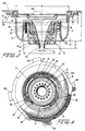
- Fig. 4 illustrates the adjustable dispenser from a top view.
- the dispenser apparatus comprises a plurality of platforms 75 to retain the collar 40 adjacent the base 20.
- the platforms 75 assist in aligning the apertures 44 of the collar 40 with the apertures 24 of the base 20. These platforms are shown maintaining the collar 40 within the dispenser apparatus when the dispenser nozzle 10 is in a fully-open position. The platforms 75 ensure that the collar 40 is not removed from the towel dispenser.
- the base 20 further includes a plurality of notches 76 for the collar 40 to engage as it is further threaded onto the base 20.
- the notches 76 provide a secure yet flexible attachment of the collar 40 to the dispenser nozzle 10.
- the towel dispenser further includes a lock 80 for securing the nozzle 10 to the towel dispenser.
- the dispenser nozzle 10 includes four platforms 75 and twelve positioning notches 76.
- the exact number of platforms 75 and notches 76 are not limiting.
- the dispenser nozzle 10 may include varying numbers of notches 76 and platforms 75 as long as they provide a similar or suitable function to the dispenser nozzle 10.
- the towel dispenser (not shown) further includes an opening (not shown) through which the towels exit the towel dispenser and enter the dispenser nozzle 10.
- the distance between the opening of the towel dispenser and the nozzle 10 is defined as B, as shown in Fig. 3.
Landscapes
- Health & Medical Sciences (AREA)
- Public Health (AREA)
- Engineering & Computer Science (AREA)
- Mechanical Engineering (AREA)
- Containers And Packaging Bodies Having A Special Means To Remove Contents (AREA)
- Details Of Rigid Or Semi-Rigid Containers (AREA)
- Reverberation, Karaoke And Other Acoustics (AREA)
- Percussion Or Vibration Massage (AREA)
- Telephone Function (AREA)
Abstract
Description
- The present invention relates to a dispensing nozzle for a towel dispenser, the nozzle being adjustable so as to accommodate towels of different thicknesses.
- Paper towels have many uses and are commonly used or cleaning and drying various surfaces. Typically, the towels will come from the manufacturer in a rolled or folded configuration, with or without perforations. Whether the towels are in a perforated format or nonperforated format, the tearing of the towels is not precise, resulting in unnecessary discard of partially torn towels or the extra towels used. Thus, it has become common practice for towel dispensers to contain sharp or tensioned edges to ease the user in the tearing process.
- Several towel dispensers providing structures for separating the towel from the web have been patented. US-A-4,905,868, forming the basis for the preamble of the independent claim, discloses a dispenser nozzle, along with an exit aperture, for a paper towel dispenser for accurately and reliably dispensing individual towels from a continuous web of towels. The nozzle has a conical shape for passing the paper towels therethrough, and causing each paper towel to be compressed as it moves through the nozzle. As a result, the friction between the paper towel and the inside of the nozzle eventually causes the dispensed paper towel to be separated from the web of towels. Furthermore, the diameter of the exit aperture of the nozzle may be enlarged in order to accommodate thicker paper towels. To enlarge the exit aperture of the nozzle, an operator removes the tip of the nozzle by cutting, clipping or breaking. Once the operator enlarges the exit aperture, the same nozzle cannot be narrowed to accommodate a thinner towel. Thus, to narrow the exit aperture of the nozzle, the operator must replace the old nozzle portion with a new nozzle portion.
- Other examples of patented towel dispensers include: US-A-4,648,530 disclosing a dispenser for perforated precut folded or rolled towels and, US-A-4,387,832 disclosing a dispenser for pre-moistened perforated towels.
- While each of the above described towel dispensers function adequately, they each have drawbacks. The major drawback is that the dispenser requires that the towels be perforated, thus providing an additional cost due to the manufacturing of the towel. Furthermore, the nozzle according to US-A-4,905,868, while not requiring the extra cost of perforated towels, achieves an extra expense in necessitating a replacement nozzle to accommodate a thinner towel.
- Therefore, what is desirable is a dispenser with a nozzle having a durable exterior capable of tearing towels, to be fitted to a paper towel container for accurately dispensing paper towels without unnecessary discarding, wherein the exit aperture of the nozzle is adjustable according to the thickness of the towel.
- An adjustable nozzle for a dispenser is known from GB-A-677 336. This prior art nozzle is provided on a bottle or a collapsible tube and can be used to regulate the flow of liquid therefrom. However, there is no mention that a development of the disclosed nozzle could be used with a towel dispenser. The known nozzle also has the disadvantage that there is no provision for ensuring that the aperture size set by the fixture is maintained during subsequent use of the dispenser. This is important for a towel dispenser where the set aperture size should remain unchanged until the dispenser is to be used with towels of different thickness.
- It is therefore an object of the present invention to provide an adjustable dispenser nozzle for use with a towel dispenser.
- Furthermore, it is a further object of the invention to provide an adjustable nozzle, which can be adjusted to enlarge or decrease the size of the exit aperture for dispensing the towel, with means for maintaining the aperture at the adjusted size during subsequent use.
- In accordance with the invention, there is provided a dispensing nozzle according to the subject-matter of independent claim 1.
- Preferred embodiments of the dispensing nozzle according to the invention are specified in the dependent claims 2 to 9.
- The present invention will now be described in detail with reference to the attached drawings, in which:
- Fig. 1 is a sectional view of an adjustable dispenser nozzle according to the present invention in a fully open position;
- Fig. 2 is a sectional view of an adjustable dispenser nozzle according to the present invention in a thread-start position;
- Fig. 3 is a sectional view of an adjustable dispenser nozzle according to the present invention in a fully narrowed position; and
- Fig. 4 is a top view of an adjustable dispenser nozzle according to the present invention.
-
- Paper towels are dispensed from a number of different types of containers. Some containers are designed for dispensing precut or z-folded towels. Other containers are designed for dispensing towels, wherein the dispensed towels are pulled from either the inside or outside of a roll.
- Although the disclosed invention may have broad applicability, it relates primarily to a nozzle for a dispenser adapted to dispense towels from the inside of a continuous roll. The dispenser may include a box-like structure, comprised of either metal or a plastic material, having an aperture in the center of the bottom thereof. A nozzle is fitted within the aperture in order to facilitate separating the towel from the web of towels in the dispenser, and furthermore to facilitate removal of the towels from the dispenser.
- Fig. 1 illustrates a novel
adjustable nozzle 10 for such a towel dispenser. Thedispenser nozzle 10 includes abase 20 having aconical portion 21 therein. Theconical portion 21 defines achannel 15 through which towels (not shown) are pulled as they are dispensed. Additionally, theconical portion 21 has anarrow end 23 defining anaperture 6b. The towels exit thedispenser nozzle 10 through thechannel 15 and theaperture 6b. - In a preferred embodiment, the
conical portion 21 of thebase 20 includes a plurality ofextensions 8 that are defined and separated by substantiallyparallel slits 9. These slits 9 impart an elastic characteristic to theconical portion 21. Furthermore, theconical portion 21 has a bottom edge 7b upon which the towels may be torn as they are dispensed from thedispenser nozzle 10. - The
base 20 further includes anouter wall 30 for engaging the towel dispenser. Theouter wall 30 includes acurved bottom 31 at one edge thereof. In addition, theouter wall 30 includes arim 32A from which extend a plurality oftabs 32B for securing thebase 20 to the towel dispenser. Therim 32A extends perpendicularly from theouter wall 30, and thetabs 32B are parallel to and extend outwardly from therim 32A. - Turning attention to Fig. 3, the towel dispenser includes an
outer wall 3 having a surface 4. The surface 4 includes a plurality ofplatforms 4A. Theplatforms 4A engage with thetabs 32B of thenozzle 10. When thedispenser nozzle 10 is attached to the towel dispenser, therim 32A remains outside of the towel dispenser. Thetabs 32B of theouter wall 30 provide a contact between the towel dispenser and thedispenser nozzle 10. - The
curved bottom 31 of thebase 20 is used as a gripping surface when replacing thedispenser nozzle 10. Thedispenser nozzle 10 may be replaced by rotating thenozzle 10 so that thetabs 32B are free from theplatforms 4A, and then pulling thedispenser nozzle 10 in a direction away from the towel dispenser. - The
base 20 of thedispenser nozzle 10 may be comprised of an elastomeric material. In a preferred embodiment the material is a hard rubber known as ABS. However, instead of ABS, the base may be made from another material having a similar quality and characteristic. Due to the combination of the plurality ofslits 9, theextensions 8 and the elasticity provided by the ABS, narrowing and expanding theexit aperture 6b of thebase 20 is enabled. - The
base 20 includes an interior wall 27 (see Fig. 2) having anexterior surface 22b and aninterior surface 22a. Theexterior surface 22b of thebase 20 is threaded so as to receive a fixture, such as acollar 40 or a nut. Thecollar 40 includes a reciprocatingly threadedinterior wall 45. Thus, thecollar 40 may be threaded onto the threadedexterior surface 22b of the base 20 in a manner similar to attaching a nut to a bolt. - The
collar 40 further includes aconical projection 41. Theconical projection 41 protrudes inwardly toward thechannel 15. Theconical projection 41 also includes abottom edge 7f having anaperture 6f therein, through which the towels pass as they are dispensed from thedispenser nozzle 10. When theextensions 8 of the base 20 do not protrude beyond thebottom edge 7f of theconical projection 41, the bottom edge 7b of thebase 20 provides a suitable surface upon which the towels may be torn as they are dispensed. - The
extensions 8 of the base 20 are located within theconical projection 41 of thecollar 40. Furthermore, theexit aperture 6f thecollar 40 is concentric with theexit aperture 6b of thebase 20. Thus, theexit aperture 6f of thecollar 40 together with theexit aperture 6b of thebase 20, combine to form anexit aperture 70 of thedispenser nozzle 10. In addition, theconical projection 41 of thecollar 40, together with theconical portion 21 of the base 20 define thechannel 15 through which the towels pass as they are dispensed. - The
collar 40 further includes a shoulder 48 (Fig. 1) adjacent the threadedinterior wall 45 of thecollar 40. In addition, thebase 20 includes acorresponding shoulder 38 adjacent the threadedexterior surface 22b of theinterior wall 27. Theshoulder 38 of thebase 20 extends in a perpendicular direction away from the threadedexterior surface 22b, and is parallel to theshoulder 48 of thecollar 40. When thecollar 40 is completely threaded onto theexterior wall 22b of thebase 20, there is a distance N between theshoulder 38 of thebase 20 and theshoulder 48 of thecollar 40. - The
shoulder 48 of thecollar 40 includes a plurality ofapertures 44 extending therethrough (see figs. 1 and 2). Additionally, theshoulder 38 of thebase 20 includes a plurality ofsimilar apertures 24 extending therethrough. See Fig. 4. Both theapertures 24 of theshoulder 38 and theapertures 44 of theshoulder 48 are adapted to receive a locking means, such as aset screw 60. Thus, when thecollar 40 has been threaded onto the base 20 to the extent necessary to achieve a desired width of theexit aperture 70, theapertures set screw 60 may be inserted through therespective apertures exit aperture 70 at the desired width. - The
collar 40 further includes a plurality of teeth (not shown) comprised of a flexible material. The teeth extend perpendicularly from theshoulder 48 of thecollar 40 toward theouter wall 30 of thebase 20. Turning attention to Fig. 4, thedispenser nozzle 10 further includes a plurality of slottedopenings 77. The slottedopenings 77 act as a spring mechanism to the teeth of thecollar 40, thus allowing the teeth to flex inward toward thechannel 15 as thecollar 40 is adjusted. - The
collar 40 may be comprised of an acetal material, providing thecollar 40 with a semi-rigid characteristic. Preferably, thecollar 40 is made from a material that is more rigid than the material from which thebase 20 is made. However, instead of acetal, the collar may be made from another material of similar quality and character. Thus, due to the nature of the material, as theexit aperture 70 of thedispenser nozzle 10 is narrowed or expanded, the diameter C of theaperture 6f of thecollar 40 remains relatively constant. - The
dispenser nozzle 10 further includes a channel member in the form of asleeve 50. See Fig. 3. Thesleeve 50 includes ahead 58, which rests flush against theinterior surface 22a of thebase 20. Thesleeve 50 further includes aconical portion 51 having a smooth tapered surface, which lines the interior part of thechannel 15. Theconical portion 51 of thesleeve 50 extends along the length of thechannel 15. Thus, when thesleeve 50 is mounted within thedispenser nozzle 10, the sleeve defines thechannel 15 through which towels pass as they exit the towel dispenser. Theconical portion 51 of thesleeve 50 is concentric with theextensions 8 of thebase 20, theconical projection 41 of thecollar 40, and theexit aperture 70. - Furthermore, the
sleeve 50 includes an exit aperture 6s which limits theexit aperture 70 as the sleeve protrudes beyond thebottom edge 7f of thecollar 40. This position is attained when thecollar 40 is fully threaded onto thebase 20. Thesleeve 50 also includes a bottom edge 7s, upon which the towels may be torn as they exit thedispenser nozzle 10. - In a preferred embodiment, the
sleeve 50 may be comprised of a thermoset rubber material, such as polyurethane. However, instead of polyurethane, thesleeve 50 may be made from another material having suitable and or similar quality. The material of thesleeve 50 enables it to expand or contract to accommodate adjustments made to thedispenser nozzle 10. - Figures 2 and 3 respectively illustrate the
adjustable dispenser nozzle 10 in the "Thread-Start Position" and the "Fully Narrowed Position". In Fig. 2, thecollar 40 is in a fully open position. Fig. 3 illustrates thedispenser nozzle 10 as thecollar 40 is fully threaded onto thebase 20, such that theshoulder 38 of thebase 20 is within a small distance N of theshoulder 48 of thecollar 40. - When the
collar 40 is fully threaded onto thebase 20, thebottom edges 7f, 7b and 7s of thecollar 40, thebase 20, and thesleeve 50, respectively, extend beyond thecurved bottom 31 of thebase 20. When thecollar 40 is completely threaded onto thebase 20, a maximum distance, defined as H, between thecurved bottom 31 of thebase 20 andprimary exit aperture 70 is achieved. - Fig. 4 illustrates the adjustable dispenser from a top view. The dispenser apparatus comprises a plurality of
platforms 75 to retain thecollar 40 adjacent thebase 20. In addition, theplatforms 75 assist in aligning theapertures 44 of thecollar 40 with theapertures 24 of thebase 20. These platforms are shown maintaining thecollar 40 within the dispenser apparatus when thedispenser nozzle 10 is in a fully-open position. Theplatforms 75 ensure that thecollar 40 is not removed from the towel dispenser. - The base 20 further includes a plurality of
notches 76 for thecollar 40 to engage as it is further threaded onto thebase 20. Thenotches 76 provide a secure yet flexible attachment of thecollar 40 to thedispenser nozzle 10. In addition, the towel dispenser further includes a lock 80 for securing thenozzle 10 to the towel dispenser. - In a preferred embodiment, the
dispenser nozzle 10 includes fourplatforms 75 and twelvepositioning notches 76. However, the exact number ofplatforms 75 andnotches 76 are not limiting. Thedispenser nozzle 10 may include varying numbers ofnotches 76 andplatforms 75 as long as they provide a similar or suitable function to thedispenser nozzle 10. - The towel dispenser (not shown) further includes an opening (not shown) through which the towels exit the towel dispenser and enter the
dispenser nozzle 10. The distance between the opening of the towel dispenser and thenozzle 10 is defined as B, as shown in Fig. 3. - For purposes of completeness, specific dimensions of a preferred embodiment are set forth below. The following is a chart of the dimensions of the
dispenser nozzle 10 in a Thread Start Position:Item Dimension mm (inches) Diameter A 15.24 mm (0.600) Distance F 10.16 mm (0.400) Distance L 73.86 mm (2.908) Distance M 108.2 mm (4.260) Radius R 25.40 mm (1.00) - The following is a chart of the varying dimensions of the
dispenser nozzle 10 in a Fully Closed Position:Item Dimension mm (inches) Diameter D 7.16 mm (0.282) Distance B 2.05 mm (0.081) Distance G 10.31 mm (0.406) Distance H 14.63 mm (0.576) Distance J 5.76 mm (0.227) Distance K 58.95 mm (2.321) Distance L 73.86 mm (2.908) Distance M 108.2 mm (4.260) Distance N 1.19 mm (0.047) - Although the present invention has been described in connection with preferred embodiments thereof, it will be appreciated by those skilled in the art that additions, deletions, modifications, and substitutions not specifically described may be made without departing from the scope of the invention as defined in the appended claims.
Claims (9)
- A dispensing nozzle (10) for use with a towel dispenser (3), comprising: a base (20) which is attachable to the towel dispenser (3); a channel member (21;50) with an exit aperture (6b;6s) through which the towels pass as they exit the dispenser and which is adjustable in size; characterized in that a fixture (40) is mounted to the base (20) and adjustable to any of a plurality of operative positions with respect to the base for determining the size of the exit aperture, and in that means (76;24,44,60) are provided for retaining the fixture (40) relative to the base (20) in a selected one of said plurality of operative positions.
- A nozzle as claimed in claim 1, characterized in that the retaining means comprises notches (76) on the base (20) and that the fixure (40) is engageable with the notches for determining said plurality of operative positions.
- A nozzle as claimed in claim 2, characterized in that the notches (76) are provided on an inner surface of the base (20) and that the fixture (40) comprises a lateral shoulder (48) engageable with the notches (76).
- A nozzle as claimed in claim 1, characterized in that the retaining means comprises apertures (24) in a flange (38) extending from the base (20) adjacent the channel member (21), apertures (44) in a lateral shoulder (48) on the fixture (49), and securing means (60) that fit through the aperture (24,22) so as to lock the fixutre to the base.
- A nozzle as claimed in any of claims 1-4, characterized by matching threaded surfaces (22b,45) on the base (20) and the fixture (40) so that the fixure (40) may be threaded onto the base, and rotated to assume any of said operative positions.
- A nozzle as claimed in any of claims 1-5, characterized in that the channel member (21) is formed on the base (20).
- A nozzle as claimed in claim 6, characterized in that the channel member (21) adjacent the exit aperture (6b) includes axially extending slits (9) which enable the exit aperture (6b) to be contracted.
- A nozzle as claimed in any of claims 1-5, characterized in that the base (20) includes a tubular member (21) having an outer end (23), which extends through the fixture (40) and has axially extending slits (9), and in that the channel member comprises a sleeve (50) forming a lining within the channel member (21).
- A nozzle as claimed in any of claims 1-8, characterized in that the channel member (21;50) comprises a tear edge (7b;7s) adjacent the exit aperture (6b;6s) enabling the towels to be torn after exiting the exit aperture (6b,6s).
Applications Claiming Priority (2)
| Application Number | Priority Date | Filing Date | Title |
|---|---|---|---|
| US07/928,059 US5263607A (en) | 1992-08-11 | 1992-08-11 | Adjustable nozzle for a dispenser and method of using same |
| US928059 | 1997-09-12 |
Publications (2)
| Publication Number | Publication Date |
|---|---|
| EP0595779A1 EP0595779A1 (en) | 1994-05-04 |
| EP0595779B1 true EP0595779B1 (en) | 2000-04-19 |
Family
ID=25455656
Family Applications (1)
| Application Number | Title | Priority Date | Filing Date |
|---|---|---|---|
| EP19930850154 Expired - Lifetime EP0595779B1 (en) | 1992-08-11 | 1993-08-10 | Dispensing nozzle |
Country Status (5)
| Country | Link |
|---|---|
| US (1) | US5263607A (en) |
| EP (1) | EP0595779B1 (en) |
| AT (1) | ATE191837T1 (en) |
| CA (1) | CA2101295C (en) |
| DE (1) | DE69328402D1 (en) |
Cited By (2)
| Publication number | Priority date | Publication date | Assignee | Title |
|---|---|---|---|---|
| USD488655S1 (en) | 2003-04-04 | 2004-04-20 | Kimberly-Clark Worldwide | Dispenser for absorbent paper products |
| US7510137B2 (en) | 2007-05-24 | 2009-03-31 | Kimberly-Clark Worldwide, Inc. | Dispenser for sheet material |
Families Citing this family (38)
| Publication number | Priority date | Publication date | Assignee | Title |
|---|---|---|---|---|
| NO941473D0 (en) * | 1994-04-22 | 1994-04-22 | Krisko Norge | Wall holder for damp sanitary napkins |
| US5564645A (en) * | 1995-02-24 | 1996-10-15 | Minnesota Mining And Manufacturing Company | Roll support hub braking mechanism |
| US5857642A (en) * | 1997-08-25 | 1999-01-12 | Hygiene Systems, Inc. | Paper towel dispenser |
| US6179506B1 (en) | 1999-06-29 | 2001-01-30 | Andrew Terrance Kevin Dewberry | Caulking accessory |
| US7025301B1 (en) * | 1999-12-30 | 2006-04-11 | Von Drehle Corporation | Dispenser |
| US6510964B2 (en) * | 2000-11-13 | 2003-01-28 | Englewood Ventures, Inc. | Center-pull sheet material dispenser |
| US7275672B2 (en) | 2001-09-11 | 2007-10-02 | Alwin Manufacturing Company, Inc. | Center pull dispenser with self-adjusting dispenser mechanism |
| US6592001B2 (en) | 2001-12-18 | 2003-07-15 | Kimberly-Clark Worldwide | Dispenser for sheet material containing a dispensing port incrementally variable within a range |
| US6629667B2 (en) | 2001-12-28 | 2003-10-07 | Kimberly-Clark Corporation | Dispenser for sheet material |
| US6575397B1 (en) | 2002-04-25 | 2003-06-10 | Kimberly-Clark Worldwide, Inc. | Dispenser for sheet material |
| US20060180596A1 (en) * | 2004-03-19 | 2006-08-17 | Allen Young | Wipe dispensing system |
| US20050205593A1 (en) * | 2004-03-19 | 2005-09-22 | Allen Young | Wipe dispensing system |
| US7040568B2 (en) * | 2004-04-02 | 2006-05-09 | Kimberly-Clark Worldwide, Inc. | Dispenser for sheet material |
| US7530460B2 (en) * | 2004-06-30 | 2009-05-12 | Kimberly-Clark Worldwide, Inc. | Dispenser for rolled sheet material |
| US6964395B1 (en) | 2004-06-30 | 2005-11-15 | Kimberly-Clark Worldwide, Inc. | Dispenser for rolled sheet material |
| GB2441323A (en) * | 2006-08-29 | 2008-03-05 | Michael John Gordon | Wipes container with dispensing nozzle |
| US7997443B2 (en) * | 2007-11-13 | 2011-08-16 | Cintas Corporation | Center-pull paper towel dispenser |
| US7997522B2 (en) * | 2007-11-13 | 2011-08-16 | Cintas Corporation | Center-pull paper towel dispenser |
| WO2010102648A1 (en) * | 2009-03-13 | 2010-09-16 | Jan Folkmar | Two part nozzle and piping bags therefrom |
| US8245876B2 (en) * | 2009-07-15 | 2012-08-21 | The Procter & Gamble Company | Wipes container |
| JP5484842B2 (en) * | 2009-09-17 | 2014-05-07 | 大王製紙株式会社 | Household thin paper storage container |
| GB2488336A (en) * | 2011-02-23 | 2012-08-29 | Bioprogress Technology Ltd | Sheet dispenser |
| ES2659726T3 (en) * | 2011-10-21 | 2018-03-19 | Sca Tissue France | Dispenser for static roll without core of central feeding of sheet product |
| US9457361B2 (en) * | 2011-11-11 | 2016-10-04 | Eley Corporation | Spray nozzle attachment and methods therefor |
| US9113760B2 (en) | 2011-12-06 | 2015-08-25 | Alwin Manufacturing Co., Inc. | Low-material-indicating center pull dispenser |
| PL2606795T3 (en) * | 2011-12-20 | 2018-02-28 | Sca Tissue France | Sheet product dispenser |
| US10231580B2 (en) | 2014-07-07 | 2019-03-19 | GPCP IP Holdings LLC. | Multiple orifice nozzle with cavity |
| GB201419730D0 (en) * | 2014-11-05 | 2014-12-17 | Kennedy Hygiene Products Ltd | Towel dispenser |
| USD771968S1 (en) | 2015-01-21 | 2016-11-22 | Cintas Corporation | Dispenser |
| FR3032341B1 (en) * | 2015-02-06 | 2017-10-27 | Maurice Granger | DISTRIBUTOR APPARATUS FOR BANDS OF HORIZONTAL OR VERTICAL POSITIONED COIL FLEXIBLE MATERIAL |
| USD775853S1 (en) | 2015-07-21 | 2017-01-10 | Cintas Corporation | Soap dispenser |
| US10334996B2 (en) * | 2017-01-26 | 2019-07-02 | Essity Hygiene And Health Aktiebolag | Paper dispenser and related methods |
| US10369589B2 (en) * | 2017-05-12 | 2019-08-06 | Alan Dale | Nozzle adapter |
| US10849470B2 (en) * | 2017-12-15 | 2020-12-01 | Gojo Industries, Inc. | Wipes dispensers and easy load adjustable dispensing nozzle |
| US11224314B2 (en) | 2019-05-31 | 2022-01-18 | San Jamar, Inc. | Web material center-pull dispenser assembly |
| USD984824S1 (en) | 2019-05-31 | 2023-05-02 | San Jamar, Inc. | Center pull-through dispenser |
| US11737617B2 (en) * | 2021-04-08 | 2023-08-29 | Juliana Hamza | Towel dispenser |
| CN118748920A (en) * | 2022-03-31 | 2024-10-08 | 爱适瑞卫生健康产品有限公司 | Outlet assembly for a dispenser of absorbent web material |
Family Cites Families (22)
| Publication number | Priority date | Publication date | Assignee | Title |
|---|---|---|---|---|
| US1291279A (en) * | 1917-02-19 | 1919-01-14 | George R Unkefer | Receptacle. |
| US1545182A (en) * | 1923-09-11 | 1925-07-07 | Joseph W Beck | Bolt lock |
| GB677336A (en) * | 1949-06-03 | 1952-08-13 | Andor Weiss | Improvements in or relating to closures for bottles and the like |
| US2801133A (en) * | 1953-07-31 | 1957-07-30 | Blastcrete Equipment Co Inc | Angle nozzle |
| US2780388A (en) * | 1954-05-04 | 1957-02-05 | Continental Can Co | Adjustable cup dispenser |
| US3058632A (en) * | 1957-05-17 | 1962-10-16 | William G Stremmel | Extension accessory for caulking tube |
| US2953285A (en) * | 1958-08-25 | 1960-09-20 | Henry P Mckelvey | Extension nozzle |
| US3261558A (en) * | 1962-01-23 | 1966-07-19 | Clevite Corp | Rocket fluid discharge nozzle |
| US3112883A (en) * | 1962-06-08 | 1963-12-03 | Hms Associates Co | General purpose variable pattern hose nozzle |
| US3776470A (en) * | 1971-09-30 | 1973-12-04 | Gen Mills Inc | Variable nozzle |
| DE2359677A1 (en) * | 1973-11-30 | 1975-06-12 | Gerdes & Co | Culinary device for decorating cakes etc. with whipped or butter cream - has disposable ('one-way') squeeze bag with fitted nozzle for extruding the cream |
| US4196824A (en) * | 1979-01-31 | 1980-04-08 | Roch Labelle | Pasta dispenser |
| US4387832A (en) * | 1981-02-24 | 1983-06-14 | Sterling Drug Inc. | Pre-moistened towelette dispensing package including flexibly adjustable tie device |
| US4382530A (en) * | 1981-07-01 | 1983-05-10 | Anthony Calisto | Interchangeable nozzle apparatus |
| DE8123069U1 (en) * | 1981-08-06 | 1981-11-12 | Kospro GmbH, 3300 Braunschweig | Plastic container for towels |
| ES287085Y (en) * | 1982-07-27 | 1986-10-16 | Granger Maurice | AUTOMATIC DISTRIBUTOR OF MATERIALS IN PRE-CUT TAPES AND ROLLED OR Z-FOLDED. |
| ATE19937T1 (en) * | 1982-11-29 | 1986-06-15 | Unilever Nv | WET TOWEL DISPENSER. |
| US4905868A (en) * | 1987-12-31 | 1990-03-06 | Beane Stephen B | Paper towel dispenser nozzle having a flange and a conical funnel |
| US4915257A (en) * | 1988-04-11 | 1990-04-10 | Bailey Curtis C | Rough service paper dispensers |
| US5074431A (en) * | 1990-05-29 | 1991-12-24 | Sendelbach Herman E | Paper plate pantry |
| US5104013A (en) * | 1990-10-15 | 1992-04-14 | Myro, Inc. | Caulking tube nozzle adaptor adjustable for different caulk bead sizes |
| US5141171A (en) * | 1991-06-26 | 1992-08-25 | U-Maek Industry Co., Ltd. | Structure of dispensing hopper for paper roll holder |
-
1992
- 1992-08-11 US US07/928,059 patent/US5263607A/en not_active Expired - Fee Related
-
1993
- 1993-07-26 CA CA 2101295 patent/CA2101295C/en not_active Expired - Fee Related
- 1993-08-10 EP EP19930850154 patent/EP0595779B1/en not_active Expired - Lifetime
- 1993-08-10 DE DE69328402T patent/DE69328402D1/en not_active Expired - Lifetime
- 1993-08-10 AT AT93850154T patent/ATE191837T1/en not_active IP Right Cessation
Cited By (2)
| Publication number | Priority date | Publication date | Assignee | Title |
|---|---|---|---|---|
| USD488655S1 (en) | 2003-04-04 | 2004-04-20 | Kimberly-Clark Worldwide | Dispenser for absorbent paper products |
| US7510137B2 (en) | 2007-05-24 | 2009-03-31 | Kimberly-Clark Worldwide, Inc. | Dispenser for sheet material |
Also Published As
| Publication number | Publication date |
|---|---|
| DE69328402D1 (en) | 2000-05-25 |
| CA2101295A1 (en) | 1994-02-12 |
| EP0595779A1 (en) | 1994-05-04 |
| US5263607A (en) | 1993-11-23 |
| CA2101295C (en) | 1996-02-06 |
| ATE191837T1 (en) | 2000-05-15 |
Similar Documents
| Publication | Publication Date | Title |
|---|---|---|
| US5263607A (en) | Adjustable nozzle for a dispenser and method of using same | |
| US5246137A (en) | Center-pull roll product dispenser with nozzle inserts | |
| US5857642A (en) | Paper towel dispenser | |
| US4905868A (en) | Paper towel dispenser nozzle having a flange and a conical funnel | |
| US5205455A (en) | Dispenser with stabilizer for coreless roll products | |
| US5370336A (en) | Dispenser apparatus for sequentially dispensing from coreless rolls of sheet material | |
| EP0091411B1 (en) | Holder for paper roll with central dispensing of the paper | |
| US6138939A (en) | Coreless adapter for dispensers of cored rolls of material | |
| US6129240A (en) | Dispenser nozzle and method for dispensing individual sheets from the center of a coreless roll product | |
| US5310083A (en) | Center-pull nozzle with modified cone | |
| US6328252B1 (en) | Dispenser of paper sheets in roll form with central unwinding | |
| EP1086646B1 (en) | Counter-top paper towel holder | |
| US5065924A (en) | Paper towel dispenser with central unwinding | |
| US6769589B2 (en) | Center-pull sheet material dispenser | |
| US5749492A (en) | Sheet dispenser and method | |
| US6386479B1 (en) | Coreless roll carriage unit adapter for dispensers | |
| EP0107487A1 (en) | Improvements in sheet material dispensers | |
| US7111805B2 (en) | Dispenser with cam controlled blades | |
| US6382553B1 (en) | Stackable coreless roll carriage unit adapter for dispensers | |
| AU642016B2 (en) | Device for use in varying the effective cross-sectional area of an outlet opening of a dispensing unit | |
| US6695190B1 (en) | Tape dispensing device | |
| US7530460B2 (en) | Dispenser for rolled sheet material | |
| US7523510B1 (en) | Sanitary plunger | |
| US5634570A (en) | Dispenser for linerless labels | |
| GB2104871A (en) | A paper dispenser |
Legal Events
| Date | Code | Title | Description |
|---|---|---|---|
| PUAI | Public reference made under article 153(3) epc to a published international application that has entered the european phase |
Free format text: ORIGINAL CODE: 0009012 |
|
| AK | Designated contracting states |
Kind code of ref document: A1 Designated state(s): AT BE CH DE DK ES FR GB GR IE IT LI LU MC NL PT SE |
|
| 17P | Request for examination filed |
Effective date: 19940603 |
|
| 17Q | First examination report despatched |
Effective date: 19950818 |
|
| GRAG | Despatch of communication of intention to grant |
Free format text: ORIGINAL CODE: EPIDOS AGRA |
|
| RTI1 | Title (correction) |
Free format text: DISPENSING NOZZLE |
|
| GRAG | Despatch of communication of intention to grant |
Free format text: ORIGINAL CODE: EPIDOS AGRA |
|
| GRAG | Despatch of communication of intention to grant |
Free format text: ORIGINAL CODE: EPIDOS AGRA |
|
| GRAH | Despatch of communication of intention to grant a patent |
Free format text: ORIGINAL CODE: EPIDOS IGRA |
|
| RAP1 | Party data changed (applicant data changed or rights of an application transferred) |
Owner name: SCA HYGIENE PRODUCTS AB |
|
| GRAH | Despatch of communication of intention to grant a patent |
Free format text: ORIGINAL CODE: EPIDOS IGRA |
|
| GRAA | (expected) grant |
Free format text: ORIGINAL CODE: 0009210 |
|
| AK | Designated contracting states |
Kind code of ref document: B1 Designated state(s): AT BE CH DE DK ES FR GB GR IE IT LI LU MC NL PT SE |
|
| PG25 | Lapsed in a contracting state [announced via postgrant information from national office to epo] |
Ref country code: LI Free format text: LAPSE BECAUSE OF FAILURE TO SUBMIT A TRANSLATION OF THE DESCRIPTION OR TO PAY THE FEE WITHIN THE PRESCRIBED TIME-LIMIT Effective date: 20000419 Ref country code: IT Free format text: LAPSE BECAUSE OF FAILURE TO SUBMIT A TRANSLATION OF THE DESCRIPTION OR TO PAY THE FEE WITHIN THE PRESCRIBED TIME-LIMIT;WARNING: LAPSES OF ITALIAN PATENTS WITH EFFECTIVE DATE BEFORE 2007 MAY HAVE OCCURRED AT ANY TIME BEFORE 2007. THE CORRECT EFFECTIVE DATE MAY BE DIFFERENT FROM THE ONE RECORDED. Effective date: 20000419 Ref country code: GR Free format text: LAPSE BECAUSE OF NON-PAYMENT OF DUE FEES Effective date: 20000419 Ref country code: FR Free format text: LAPSE BECAUSE OF FAILURE TO SUBMIT A TRANSLATION OF THE DESCRIPTION OR TO PAY THE FEE WITHIN THE PRESCRIBED TIME-LIMIT Effective date: 20000419 Ref country code: ES Free format text: THE PATENT HAS BEEN ANNULLED BY A DECISION OF A NATIONAL AUTHORITY Effective date: 20000419 Ref country code: CH Free format text: LAPSE BECAUSE OF FAILURE TO SUBMIT A TRANSLATION OF THE DESCRIPTION OR TO PAY THE FEE WITHIN THE PRESCRIBED TIME-LIMIT Effective date: 20000419 Ref country code: BE Free format text: LAPSE BECAUSE OF FAILURE TO SUBMIT A TRANSLATION OF THE DESCRIPTION OR TO PAY THE FEE WITHIN THE PRESCRIBED TIME-LIMIT Effective date: 20000419 Ref country code: AT Free format text: LAPSE BECAUSE OF FAILURE TO SUBMIT A TRANSLATION OF THE DESCRIPTION OR TO PAY THE FEE WITHIN THE PRESCRIBED TIME-LIMIT Effective date: 20000419 |
|
| REF | Corresponds to: |
Ref document number: 191837 Country of ref document: AT Date of ref document: 20000515 Kind code of ref document: T |
|
| REG | Reference to a national code |
Ref country code: CH Ref legal event code: EP |
|
| REF | Corresponds to: |
Ref document number: 69328402 Country of ref document: DE Date of ref document: 20000525 |
|
| REG | Reference to a national code |
Ref country code: IE Ref legal event code: FG4D |
|
| PG25 | Lapsed in a contracting state [announced via postgrant information from national office to epo] |
Ref country code: PT Free format text: LAPSE BECAUSE OF FAILURE TO SUBMIT A TRANSLATION OF THE DESCRIPTION OR TO PAY THE FEE WITHIN THE PRESCRIBED TIME-LIMIT Effective date: 20000719 Ref country code: DK Free format text: LAPSE BECAUSE OF FAILURE TO SUBMIT A TRANSLATION OF THE DESCRIPTION OR TO PAY THE FEE WITHIN THE PRESCRIBED TIME-LIMIT Effective date: 20000719 |
|
| PG25 | Lapsed in a contracting state [announced via postgrant information from national office to epo] |
Ref country code: DE Free format text: LAPSE BECAUSE OF FAILURE TO SUBMIT A TRANSLATION OF THE DESCRIPTION OR TO PAY THE FEE WITHIN THE PRESCRIBED TIME-LIMIT Effective date: 20000720 |
|
| PGFP | Annual fee paid to national office [announced via postgrant information from national office to epo] |
Ref country code: GB Payment date: 20000807 Year of fee payment: 8 |
|
| PG25 | Lapsed in a contracting state [announced via postgrant information from national office to epo] |
Ref country code: LU Free format text: LAPSE BECAUSE OF EXPIRATION OF PROTECTION Effective date: 20000810 Ref country code: IE Free format text: LAPSE BECAUSE OF NON-PAYMENT OF DUE FEES Effective date: 20000810 |
|
| PGFP | Annual fee paid to national office [announced via postgrant information from national office to epo] |
Ref country code: SE Payment date: 20000817 Year of fee payment: 8 |
|
| PG25 | Lapsed in a contracting state [announced via postgrant information from national office to epo] |
Ref country code: MC Free format text: THE PATENT HAS BEEN ANNULLED BY A DECISION OF A NATIONAL AUTHORITY Effective date: 20000831 |
|
| PGFP | Annual fee paid to national office [announced via postgrant information from national office to epo] |
Ref country code: NL Payment date: 20000831 Year of fee payment: 8 |
|
| EN | Fr: translation not filed | ||
| REG | Reference to a national code |
Ref country code: CH Ref legal event code: PL |
|
| PLBE | No opposition filed within time limit |
Free format text: ORIGINAL CODE: 0009261 |
|
| STAA | Information on the status of an ep patent application or granted ep patent |
Free format text: STATUS: NO OPPOSITION FILED WITHIN TIME LIMIT |
|
| 26N | No opposition filed | ||
| REG | Reference to a national code |
Ref country code: IE Ref legal event code: MM4A |
|
| PG25 | Lapsed in a contracting state [announced via postgrant information from national office to epo] |
Ref country code: GB Free format text: LAPSE BECAUSE OF NON-PAYMENT OF DUE FEES Effective date: 20010810 |
|
| PG25 | Lapsed in a contracting state [announced via postgrant information from national office to epo] |
Ref country code: SE Free format text: LAPSE BECAUSE OF NON-PAYMENT OF DUE FEES Effective date: 20010811 |
|
| PG25 | Lapsed in a contracting state [announced via postgrant information from national office to epo] |
Ref country code: NL Free format text: LAPSE BECAUSE OF NON-PAYMENT OF DUE FEES Effective date: 20020301 |
|
| EUG | Se: european patent has lapsed |
Ref document number: 93850154.1 |
|
| GBPC | Gb: european patent ceased through non-payment of renewal fee |
Effective date: 20010810 |
|
| NLV4 | Nl: lapsed or anulled due to non-payment of the annual fee |
Effective date: 20020301 |