EP0594923B1 - Cassette tape loading process providing for recovery of cassettes previously loaded with waste tape, and loading machine for putting the process into practice - Google Patents
Cassette tape loading process providing for recovery of cassettes previously loaded with waste tape, and loading machine for putting the process into practice Download PDFInfo
- Publication number
- EP0594923B1 EP0594923B1 EP92830658A EP92830658A EP0594923B1 EP 0594923 B1 EP0594923 B1 EP 0594923B1 EP 92830658 A EP92830658 A EP 92830658A EP 92830658 A EP92830658 A EP 92830658A EP 0594923 B1 EP0594923 B1 EP 0594923B1
- Authority
- EP
- European Patent Office
- Prior art keywords
- tape
- cassette
- leader
- waste
- waste tape
- Prior art date
- Legal status (The legal status is an assumption and is not a legal conclusion. Google has not performed a legal analysis and makes no representation as to the accuracy of the status listed.)
- Expired - Lifetime
Links
Images



Classifications
-
- G—PHYSICS
- G11—INFORMATION STORAGE
- G11B—INFORMATION STORAGE BASED ON RELATIVE MOVEMENT BETWEEN RECORD CARRIER AND TRANSDUCER
- G11B23/00—Record carriers not specific to the method of recording or reproducing; Accessories, e.g. containers, specially adapted for co-operation with the recording or reproducing apparatus ; Intermediate mediums; Apparatus or processes specially adapted for their manufacture
- G11B23/02—Containers; Storing means both adapted to cooperate with the recording or reproducing means
- G11B23/113—Apparatus or processes specially adapted for the manufacture of magazines or cassettes, e.g. initial loading into container
-
- B—PERFORMING OPERATIONS; TRANSPORTING
- B65—CONVEYING; PACKING; STORING; HANDLING THIN OR FILAMENTARY MATERIAL
- B65H—HANDLING THIN OR FILAMENTARY MATERIAL, e.g. SHEETS, WEBS, CABLES
- B65H21/00—Apparatus for splicing webs
Definitions
- the present invention relates to a cassette tape loading process providing for recovery of cassettes previously loaded with waste tape.
- the present invention also pertains to a loading machine for putting the above process into practice, said machine being of the type comprising: the features recited in the preamble of claim 9.
- cassette loading machines that, at each work cycle, pick up an empty cassette from an infeed conveyor and operatively engage it in a work station in which it is loaded with magnetic tape (hereinafter referred to as "use tape") continuously fed from a supply reel or "pancake".
- use tape magnetic tape
- An example of such a cassette loading machine is disclosed by EP-A- 0 210 844 which is herein referred as the most relevant prior art.
- the cassette reaching the loading station contains a leader connected at both ends to first and second winding hubs rotatably housed in the cassette itself.
- Suitable extractor means consisting for example of pin elements supported by respective drive arms, carry out the extraction of the leader from a front opening provided in the cassette, and deposit it onto an engagement surface and a first holding seat formed on a first support block and a second support block respectively, said blocks being disposed in side by side relation close to the front opening.
- a cutting means operates between the support blocks and cuts the leader into a leading portion engaged to the first block and connected to the first winding hub and a second portion engaged to the second block and connected to the second winding hub.
- a leading end of the use tape to be loaded engaged in a second holding seat formed in the first block is consecutively aligned with the first portion of the leader and subsequently spliced thereto through application of adhesive joining tape, upon the action of a splicing unit acting on the blocks.
- the first winding hub is driven in rotation thereby causing a predetermined amount of use tape to be wound onto the cassette.
- the use tape still engaged to the support blocks is cut by said cutting means and, by displacing the second block again, the second portion of the leader is brought into alignment with the trailing end of the loaded use tape to which it is spliced.
- a further rotation of the first winding hub causes the end portion of the use tape and the second portion of the leader to be introduced into the cassette front opening, said cassette being then ejected from the loading station, while a new cassette to be processed takes its place.
- the invention aims at solving the above problems, by a new loading process according to which it is possible to extract the waste tape from a loaded cassette in a very short time, making the cassette immediately available for being loaded with use tape again, without on the other hand giving rise to any qualitative decay of the finished product.
- the invention pertains to a cassette tape loading process providing for recovery of cassettes previously loaded with waste tape, characterized in that it comprises the steps recited in claim 1.
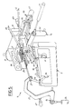
- reference numeral 1 generally denotes a cassette loading machine adapted to put into practice a cassette tape loading process providing for recovery of cassettes previously loaded with waste tape, in accordance with the present invention.
- the loading machine is arranged to operate on video cassettes of the VHS type and represents an innovation with respect to a loading machine being the object of Patent Application EP-89830147.8 in the name of the same Applicant.
- the loading machine 1 provides for the use of a cassette feeding unit consisting for example of a belt conveyor 2 on which a plurality of cassettes 3 being processed is disposed, said cassettes being sequentially conveyed to a front panel 4 of the machine.
- Delivery means 5 picks up the individual cassettes 5 from the conveyor belt 2 and sequentially engages them into a work station 6 at which each cassette undergoes the different operating steps for accomplishing the loading process.
- the delivery means 5 comprises for example an overturning device 7 that, at each operating cycle, picks up one cassette from the end of the belt conveyor 2 and disposes it vertically on first support elements carried by a transferring member 9.
- the transferring member 9 is movable along vertical guides (not shown) between one position in which it receives the cassette 3 engaged by the overturning device 7, to a second position in which said cassette is engaged in a pair of side guides 10 that, following a displacement towards the front panel 4, cause the cassette to be operatively engaged in the work station 6.
- the loading machine 1 is capable of carrying out the loading of empty audio or video cassettes (currently referred to as C-O and V-O cassettes) according to a conventional processing cycle aiming at winding a predetermined amount of use tape 12 into a cassette, which tape is continuously supplied from a pancake not shown.
- empty audio or video cassettes currently referred to as C-O and V-O cassettes
- Cassettes 3 reaching the work station 6 conventionally have a leader 13 (Fig. 3) a first portion 14 of which and a second portion 15 of which are respectively connected to first and second winding hubs, 16 and 17, rotatably housed in the cassette.
- the first and second portions, 14 and 15, of leader 13 form a single leader piece extending before a front opening 18 of the cassette 3.
- extraction means 19 arranged to suitably extract the leader 13 from the front opening 18 upon opening of a protection door 20 (Fig. 1), in a manner known per se and therefore not described.
- the extraction means 19 comprises first and second extractor elements 21, 22 engaged to the ends of a first and a second drive arm, 23, 24 respectively, and arranged to penetrate into corresponding access places 25 provided close to the front opening 18 of the cassette 3, as soon as said cassette is operatively engaged in the work station 6.
- Each extractor element 21, 22 is susceptible of being displaced, upon command of a main actuator 26, 27 acting on the corresponding drive arm 23, 24 between a rest position, in which it is introduced into the corresponding access space 25, and a maximum-extracted position in which, as shown in fig. 3, it is located at the outside of the front opening 18 of the cassette 3 to a predetermined distance therefrom.
- extractor elements 21, 22 are drivingly moved to the maximum-extracted position so that the leader 13 is extracted almost completely and laid down before the cassette front opening 18.
- the leader 13 is disposed on an engagement surface 28 exhibited by a first support block 29 and a first holding seat 30 disposed in alignment with the engagement surface 28 and exhibited by a second support block 31 disposed side by side with the first block 29.
- the engagement surface 28 and the first holding seat 30 facing the cassette front opening 18 are designed to hold the leader 13 by effect of a suction action produced through a plurality of holes 28a, 30a opening to said surface and seat.
- a first cutting means operates between the first and second blocks 29, 31 and it consists for example of a first cutter 32 operated by a respective actuator 33 that cuts the leader 13 according to a transverse direction, so as to sever it into a first portion 14 and a second portion 15.
- the first portion 14 will extend between the first support block 29 and the first winding hub 16, whereas the second portion 15 will extend between the second support block 31 and the second winding hub 17.
- the use tape 12 has a leading end 12a engaged to the second block 31 at a second holding seat 34 disposed parallelly in side by side relation with the first holding seat 30 and provided with respective suction holes 34a.
- suitable displacement means consisting of a displacement actuator 35 acting on a frame 36 carrying both blocks 29, 31 causes the simultaneous displacement of the blocks from a first operating condition in which the engagement surface 28 and holding seat 34 aligned therewith are facing the front opening 18, to a second operating condition in which said engagement surface and holding seat are operatively located in front of a splicing unit 37 mounted to the front panel 4 at a laterally offset position with respect to the cassette 3.
- the second support block 31 is moved relative to the first support block 29 so that the second holding seat 34 is brought into alignment with the engagement surface 28 of the first block and, as a consequence, the leading end 12a of the use tape to be loaded 12 is brought into alignment with the first leader portion 14 (Fig. 12).
- the splicing unit 37 by an arm means 37a movable towards the blocks 29, 31, applies a first adhesive joining tape 39 onto the ends of the first portion 14 of the leader and the leading part 12a of the tape, so as to join them consecutively.
- An abutment element 40 intermediate the blocks 29, 31 acts against the action of the arm means 37a in order to ensure an optimal adhesion of the adhesive tape to the leader 13 and use tape 12.
- This abutment element 40 is movable, upon command of a fluid-operated cylinder 41, apart from the leader 13 and tape 12 in order to make room for the first cutting member 32 when this cutting member must be operated.
- Blocks 29, 30 are then brought again to the first operating condition and, upon disengagement of the first portion 14 of the leader and the use tape to be loaded 12 by interrupting the suction effect on the engagement surface 28 and second holding seat 34, the first winding hub 16 is driven in rotation upon the action of a winding spindle 42 (Fig. 1) so as to cause the winding of a predetermined amount of use tape 12.
- the tape When the desired amount of use tape 12 has been wound onto the hub 16, the tape is engaged to the engagement surface 28 and the second holding seat 34 of blocks 29, 31 by a new displacement of the extractor element to the maximum-extracted position.
- the use tape 12 is then cut upon the action of the first cutter 32, and blocks 29, 31, upon returning of the extractor elements 21, 22 to the rest position, are brought to the second operating condition.
- the second block 31 Simultaneously with this operation, the second block 31 is moved again relative to the first block 29 so as to bring the second leader portion 15 into alignment with the trailing end 12b of the tape 12 held by the engagement surface 28.
- the splicing unit 37 is operated and it applies a second adhesive joining tape 43 (Fig. 15) to the trailing end 12b of the use tape and the second portion 15 of the leader.
- the cassette loading process is terminated by driving the first winding hub 16 in rotation again, in order to make the tape 12 and the second portion of leader 15 ultimately enter the cassette opening 18, said cassette being then released from the work station 6 and moved away by the transferring member 9.
- the leading end 12a of the use tape 12 to be loaded during a following processing cycle is still disposed on the second holding seat 34 of the second block 31.
- the above description refers to a conventional cassette loading cycle which can be executed by the loading machine 1 on C-O or V-O type cassettes.
- the loading machine 1 can also be used for recovering cassettes 3 previously loaded with waste tape 45.
- Cassettes 3 preloaded with waste tape 45 can be indiscriminately fed to the belt convevor 2 either in the absence of cassettes of the C-O or V-O type or in the presence of these cassettes, and in the latter case they can be alternated with said C-O or V-O type cassettes, even randomly.
- sensor means 44 is associated with the work station 6, being arranged to detect the presence or not of waste tape 45 within each cassette 3 being engaged in the work station.
- sensor means 44 substantially comprises at least one photoemitter 46 and one photoreceiver 47 located at the inside and outside respectively of the cassette 3 engaged in the work station 6.
- Photoemitter 46 on engagement of the cassette 3 in the work station 6, enters a housing 48 conventionally arranged in the cassette and lends itself to emit a light signal detectable by the first photoreceiver 47, through an aperture (not seen in the drawings) conventionally formed in the cassette.
- the light signal is subjected to cross the first portion 14 of the leader, at a length thereof extending from the first hub 16 to the front opening 18 of the cassette. Since, as is known, the leader 13 is made of transparent material, the light signal can reach the first photoreceiver 47.
- the second photoreceiver 49 lends itself to sense the light signal emitted from photoemitter 46 through a corresponding aperture 49a, in order to detect the presence of waste tape 45 wound onto the second hub 17, following the same modalities as previously described with reference to the first photoreceiver 47.
- a microprocessor drives the loading machine 1 in operation according to the processing cycle described above with reference to loading of C-O or V-O cassettes.
- the second portion 15 of the leader and a trailing section 45a of the waste tape 45 spliced to said leader portion are extracted from the front opening 18 and brought into engagement on the first holding seat 30 of the second support block 31 and the engagement surface 28 of the first support block 29, respectively, said holding seat and engagement surface being in mutual alignment.
- the splice between the waste tape 45 and second portion 15 of the leader, represented by the second adhesive joining tape 43 applied in the processing cycle previously executed on the same cassette is advantageously positioned on the first block 29, in such a manner that it is laterally offset towards the first block, with respect to the direction of operation of the first cutting member 32 (Figs. 4 and 7).
- This positioning of the splice is achieved by bringing the first extractor element 21 to the maximum-extracted position and simultaneously bringing the second extractor element 22 to a position intermediate the rest position and the corresponding maximum-extracted position.
- stopping of the second extractor element 22 to its intermediate position occurs by means of a first auxiliary actuator 50, that, when activated, interferes with the displacement of the second drive arm 24 in order to stop, against the action of the corresponding main actuator 27, the displacement of the second extractor element to its maximum-extracted position.
- the second portion 15 of the leader is cut and completely cleared of the second adhesive joining tape 43, which is kept attached to the trailing section 45a of the waste tape 45 held by the engagement surface 28 of the first block 29.
- connection of the trailing section 45a of the waste tape 45 with the auxiliary threading means 51 is carried out by interconnecting means 52 providing for the presence of a third holding seat 53 on the second block 31, disposed parallelly in side by side relation with the second holding seat 34.
- the third holding seat 53 is designed to hold an end portion 54a of a tape length 54 discarded in a previous processing cycle, still by effect of suction produced through holes 53a opening to said third holding seat.
- This tape length 54 has its foremost portion 54b
- This tape length 54 has its foremost portion 54b arranged in engagement on a holding element 55 being part of the auxiliary threading means 51.
- the holding element 55 substantially comprises a fixed block exhibiting a support surface on which, in this case too as a result of a suction effect, the foremost portion 54b of the tape length 54 is retained
- the second block 31 After carrying out the cut of the second portion 15 of the leader and upon return of the extractor elements 21, 22 to the rest position, the second block 31 is moved with respect to the first block 29 so that the third holding seat 53 carrying the end portion 54a of length 54 is disposed in alignment with the engagement surface 28 carrying the trailing section 45a of the waste tape 45 (Fig. 8).
- said drive means 38 should be comprised of a first movement actuator 56 the rod 56a of which (only partly shown in the drawings) acts on the second block 31 so as to move it from a first position in which the first holding seat 30 is in alignment with the engagement surface 28 to a third position in which the third holding seat 53 is in alignment with the engagement surface itself.
- a second movement actuator 57 is fixed in succession to the first actuator 56 and, when activated, said second actuator acts by its rod 57a against the rod 56a of the first actuator 56, in order to restrain the stroke of the second block 31 towards the third position, stopping it to a second position in which the alignment of the second holding seat 34 with the engagement surface 28 is achieved.
- the first and second blocks 29, 31 are brought to the second operating position and the splicing unit 37 carries out the splicing between the trailing section 45a of the waste tape 45 and the first end portion 54a of the tape length 54, by application of a third adhesive joining tape 58 (Fig. 9).
- Blocks 20, 31 are brought back to the first operating condition and, upon disengagement of the waste tape 45 and tape length 54 from said blocks by interruption of said suction effect, a step providing the extraction of the waste tape 45 from the cassette 3 is initiated upon the action of the auxiliary threading means 51.
- the auxiliary threading means 51 comprises a gripper element 59 controlled by a fluid-operated displacement cylinder 60, said gripper element being movable between a first position in which it is disposed close to the holding element 55 for picking up, as a result of a suction effect, the foremost portion 54b of length 54, and a second position in which it is moved away from the holding element 55 so that it can extend the tape length 54 in a predetermined direction.
- a winding fork 61 operates on the length portion 54 extending between the holding element 55 and gripper element 59 moved to the second position.
- Said fork in a manner known per se, is movable perpendicularly to the movement direction of the gripper element 59 between a rest position in which it does not interfere with the movement of the gripper element, and an operating position in which, as shown in Fig. 6, it operatively engages the tape length 54 at a diametrical slit 62 provided in the fork itself.
- the orientation of the diametrical slit 62 is suitably fixed by a unidirectional ratchet pawl 63 capable of interferring with an abutment notch 64 carried on the periphery of fork 61, when said fork is driven in rotation by a motor 61a in a predetermined direction, that is clockwise with reference to Fig. 6.
- the fork 61 is driven in rotation in a direction opposite to that causing the interference of the ratchet pawl 63 with the abutment notch 64 so that the fork carries out the threading and winding upon itself of the tape length 54 and waste tape 45 as it is drawn from the first hub 16.
- a count wheel 65 operatively engaged on the path of the tape length 54 and waste tape 45 being unwound is driven in rotation at an angular speed proportionate to the movement speed of the waste tape.
- the difference between the angular speeds of the count wheel 65 and first hub 16 detected bv appropriate sensors not described as known per se reaches a predetermined value, the rotational speed of the winding fork 61 is reduced in order to prevent the leader 13 from being pulled away from the first hub 16 or at all events damaged, at the end of the waste tape 45 unwinding.
- the first extractor element 21 is moved from its rest position in order to cause the engagement of the first leader portion 14 and the leading section 45b of the waste tape 45 on the engagement surface 28 of the first block 29 and the third holding seat 53 of the second block 31, respectively.
- a portion of the waste tape 45 is required to be unwound from the winding fork 61, said fork being therefore obliged to rotate in the opposite direction with respect to the winding direction.
- a release actuator 66 acting on the unidirectional ratchet pawl 63 and moving it to a position in which it does not interfere with the abutment notch 64 arranged in the fork.
- a second auxiliary actuator 67 (Fig. 5) is operated which is designed to act on the first drive arm 23 for stopping, against the action of the corresponding main actuator 26, the movement of the extractor element to a position intermediate the maximum-extracted position and rest position.
- the first cutting member 32 is operated and it cuts the first portion 14 of the leader, completely separating it from the first adesive tape 39, which is kept attached to the leading section 45b of the waste tape 45.
- the second block 31 is disposed to its second work position so that the second holding seat 34 carrying the leading end 12a of the new use tape 12 to be loaded into the cassette 3 is brought into alignment with the engagement surface 28 of the first block 29.
- the loading process goes on following the same modalities as known processes for loading C-O or V-O cassettes starting from the step of splicing the first portion of leader 14 to the leading end 12a of the use tape 12 to be wound, the operating sequence being that shown in Figs. 11 to 16.
- waste tape 45 wound on the fork 61 is cut by an auxiliary cutter 68 at the holding element 55, giving thereby origin to a new tape length 54 extending between the third holding seat 53 of the second block 31 and the holding element itself.
- the waste tape roll 69 formed on fork 61 is dropped in a manner known per se, due to the backward movement of the fork to the rest position, then the gripper element 59 can be brought back to its first work position at the holding element 55.
- the invention achieves important advantages.
Landscapes
- Replacement Of Web Rolls (AREA)
- Input Circuits Of Receivers And Coupling Of Receivers And Audio Equipment (AREA)
- Auxiliary Devices For And Details Of Packaging Control (AREA)
Abstract
Description
- Fig. 1 is a fragmentary perspective view of a work station of a machine for loading tape into cassettes, adapted to carry out the process of the present invention;
- Fig. 2 is a diagrammatic vertical section of the machine, taken at the work station;
- Fig. 3 is a diagrammatic front view showing a V-O cassette disposed in the work station, during the step of extracting the leader from the front opening thereof;
- Fig. 4 shows a cassette previously loaded with waste tape, during a step in which a second leader portion is get ready for being separated from the waste tape contained in the cassette;
- Fig. 5 shows the cassette of Fig. 4 during an operating step in which the waste tape extracted from the cassette is get ready for being separated from a first leader portion;
- Fig. 6 is another perspective view of the cassette during the step in which the waste tape is extracted therefrom by auxiliary threading means;
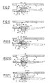
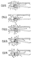
- Figs. 7 to 16 diagrammatically show, in top views, the positions taken by the support blocks with respect to the cassette being processed, during the different steps of the process in question.
Claims (24)
- A cassette tape loading process providing for recovery of cassettes previously loaded with waste tape, comprising the steps of:engaging in a work station (6) a cassette (3) containing a waste tape (45) spliced, by adhesive joining tapes (39, 43) applied to a leading section (45b) and a trailing section (45a) of said waste tape respectively, to leading and trailing portions (14, 15) respectively of a leader (13) engaged to first and second winding hubs (16, 17) housed in the cassette (3);extracting from a front opening (18) of the cassette (3), the second leader portion (15) together with the trailing section (45a) of the waste tape (45) wound on the first hub (16) of the cassette (3);cutting the second leader portion (15) in order to separate it from the trailing section (45a) of the waste tape (45);connecting the trailing section (45a) of the waste tape (45) to auxiliary threading means (51) operating at the outside of the cassette (3);unwinding the waste tape (45) from the first hub (16) through the auxiliary threading means (51), until the first portion (14) of leader (13) together with the leading section (45b) of the waste tape (45) has been extracted from the front opening (18) of the cassette (3);cutting the first portion (14) of leader (13) in order to separate it from the leading section (45b) of the waste tape (45) extracted from the cassette (3);aligning the first portion (14) of leader (13) with the leading end (12a) of a use tape (12) to be loaded into the cassette (3);splicing said leading end (12a) to the first leader portion (14);winding a desired amount of use tape (12) to be loaded, onto the first hub (16);cutting the use tape (12) loaded into the cassette (3) so as to separate a trailing end (12a) thereof from the leading end (12a) of the use tape to be loaded during a following processing cycle;aligning the trailing end (12a) of the use tape (12) loaded into the cassette (3) to the second portion (15) of leader (13);splicing the trailing end (12a) of the loaded use tape (12) to the second leader portion (15);winding the loaded use tape (12) and the second portion (15) of leader (13) joined to each other into the cassette (3) and eject the cassette (3) from the work station (6).
- A process according to claim 1, characterized in that it further comprises the following steps:engaging, simultaneously with their being extracted from the cassette, the trailing section (45a) of the waste tape (45) and second portion (15) of the leader (13) respectively, on an engagement surface (28) of a first support block (29) and a first holding seat (30) exhibited by a second support block (31) and disposed in alignment with said engagement surface (28), said first and second blocks (29, 31) being located at opposite positions relative to the direction in which said cutting steps are carried out;moving said blocks 29, 31 with respect to each other after executing the cutting of the trailing portion (15) of leader (13), so as to align the waste tape (45) with an end portion (54a) of a tape length (54) discarded in a previous operating cycle and supported by a third holding seat 53 exhibited by the second block 31 and operatively connected to said auxiliary threading means (51);splicing the waste tape (45) with the tape length (54) previously discarded in order to carry out the step of connecting the waste tape (45) to the auxiliary threading means (51).
- A process according to claim 2, characterized in that it further comprises the step of disengaging the waste tape (45) and discarded tape length (54) from said support blocks (29, 31) before carrying out the step of unwinding the waste tape (45).
- A process according to claim 2, characterized in that it further comprises the steps of:engaging the first portion (14) of leader (13) and the leading section (45b) of the unwound waste tape (45) on the engagement surface (28) of the first block (29) and the third holding seat (53) of the second block (31) respectively, before carrying out the cutting of the first portion (14) of leader (13);moving the first and second blocks (29, 31) with respect to each other in order to align the first portion (14) of leader (13) with the leading end (12a) of the use tape (12) to be loaded, carried by a second holding seat (34) exhibited by the second block (31), before carrying out the step of splicing the use tape (12) to be loaded to the first portion (14) of leader (13).
- A process according to claim 2, characterized in that, simultaneous with the step of engaging the trailing section (45a) of the waste tape (45) and the second portion (15) of leader (13) on said blocks (29, 31) respectively, a second adhesive joining tape (43) applied to the waste tape (45) and the second leader portion (15) is located to a position laterally offset towards the first block 29 with respect to the direction in which the cutting steps are carried out, so that said second adhesive joining tape (43) is kept engaged to the trailing section (45a) of the waste tape (45) following the step of cutting the second portion (15) of leader (13).
- A process according to claim 4, characterized in that, simultaneously with the step of engaging the first portion (14) of leader (13) and the leading section (45b) of the waste tape (45) on said blocks (29, 31) respectively, a first adhesive joining tape (39) applied to the leading section of the waste tape (45) and the first leader portion (13) is located to a position laterally offset towards the second block (31), with respect to the direction in which the cutting steps are carried out, so that said first adhesive joining tape (39) is kept engaged to the leading section (45b) of the waste tape (45) following the step of cutting the first portion (14) of leader (13).
- A process according to claim 1, characterized in that it further comprises the step of detecting the presence of waste tape (45) in the cassette (3) in the loading position on said first and/or second hub (16, 17).
- A process according to claim 7, characterized in that it further comprises the step of winding all of said waste tape (45) in the cassette (3) onto said first hub (16) in response to the detection of waste tape (45) on said second hub (17).
- A loading machine for loading tape cassettes, comprising:said machine being characterized in that it further comprises:at least one work station (6) arranged to operatively engage a cassette being processed (3), containing at least one leader (13) having a first portion (14) and a second portion (15) engaged to first and second winding hubs (16, 17) respectively, located in the cassette itself;extraction means (19) for extracting the leader (13) from a front opening (18) of the cassette (3);an engagement surface (28) for receiving and engaging the first portion (14) of leader (13) extracted from the cassette;a first and a second holding seats (30, 34) arranged to receive and engage the second portion (15) of leader (13) extracted from the cassette (3) and a leading end (12a) of a use tape (12) to be loaded into the cassette (3), respectively;drive means (38) for selectively aligning the first and second holding seats (30, 34) with said engagement surface (28);first cutting means (32, 33) for separating the leading and trailing portions (14, 15) of the leader (15) extracted from said front opening (18) from each other, as well as cutting the use tape (12) loaded into the cassette (3);splicing means (37) for splicing the first portion (14) of leader (13) to the leading end (12a) of the use tape (12) to be loaded, as well as the second portion (15) of leader (13) to the trailing end (12a) of the use tape (12) loaded into the cassette (3);said cutting means (32, 33) being furtherly arranged for cutting the leading and trailing potions of the leader (13) near the respective ends (45a, 45b) of the waste tape (45).auxiliary threading means (51) for extracting a waste tape (45) wound onto a first hub of the cassette (3) from the cassette itself; andinterconnecting means (52) for operatively connecting the auxiliary threading means (51) with a trailing section (45a) of the waste tape (45) previously separated from the second portion (15) of leader (13) by said cutting means (32, 33),
- A machine according to claim 9, characterized in that said interconnecting means (52) comprises at least a third holding seat (53) arranged to retain an end portion (54a) of a waste tape length (54) the foremost portion (54b) of which is engaged to the threading means (51).
- An apparatus according to claim 9, characterized in that said engagement surface (28) is disposed on a first support block (29).
- An Apparatus according to claim 9, characterized in that first and said second holding seets (30, 34) are disposed on a second block (31).
- A machine according to claim 9, characterized in that said interconnecting means (52) comprises at least a third holding seat (53) disposed parallelly in side by side relation with the first and second holding seats (30, 34) formed in the second block (31), said third holding seat (53) being capable of alignment with the engagement surface (28) carried by the first block (29) upon the action of the drive means (38), in order to enable the trailing section (45a) of the waste tape (45) to be spliced to the end portion (54a) of the tape lenght (54), upon the action of the splicing means (37).
- A machine according to claim 13, characterized in that said third holding seat (53) is formed directly in the second block (31), side by side with the second holding seat (34).
- A machine according to claim 9, characterized in that said extraction means comprises first and second extractor elements (21, 22) each movable between first, second and third positions.
- A machine according to claim 15, characterized in that said first position of said extractor elements (21, 22) is a rest position in which said extractor elements (21, 22) are positioned in an access space (25) formed in a cassette (3) engaged in said loading station (6), and wherein said second position of said extractor elements (21, 22) is and intermediate position which permits the tape extracted from a cassette (3) engaged in said loading station (6) to be shifted laterally with respect to said first, second, third and fourth tape holding means (28, 30, 34, 53).
- A machine according to claim 16, characterized in that said extraction means (19) further comprises a main actuator (26, 27), for moving said first and second extractor elements (21,22) between said rest position, and a maximum-extracted position in which it is spaced apart from, and external to the cassette front opening (18), at least one auxiliary actuator (50, 67) susceptible of activation for interrupting the stroke of the extractor element towards the maximum-extracted position and stop it at said intermediate position being associated with each extractor element (21, 22).
- A machine according to claim 9, characterized in that said auxiliary threading means (51) comprises a movable gripper element (59) for holding a foremost portion (54b) of tape lenght (54) and moving it into operative engagement with a tape take-up device (61).
- A machine according to claim 18, characterized in that said auxiliary threading means (51) comprises:said tape take-up device comprising a winding fork (61) movable between a rest position in which it does not interfere with the movements of the gripper element (59) and an operating position in which it engages the tape length (54) extended by the gripper element, said fork (61) being operable in rotation for threading and winding upon itself the tape length (54) together with the waste tape (45) previously spliced to said tape length.a holding element (55) designed to retain the foremost portion (54b) of the waste tape length (54);said gripper element (59) being movable between a first position in which it is disposed close to the holding element (55) for picking up the foremost portion (54b) of the tape length (54) and a second position in which it is spaced apart from the holding element (55) for extending the tape length (54) in a predetermined direction;
- A machine according to claim 9, characterized in that it further comprises sensor means (44) for detecting the presence of the waste tape (45) in the cassette (3) engaged in the work station (6).
- A machine according to claim 20, characterized in that said sensor means (44) comprises at least one photoemitter (46) and at least one photoreceiver (47) located inside and outside the cassette (3) engaged in the work station (ó) respectively, said photoreceiver(47) being arranged to detect the presence of the waste tape (45) wound onto the first hub (16) following the interception by the tape itself of a light signal issued from the photoemitter (46), since said leader (13) is made of transparent material.
- A machine according to claim 21, characterized in that it further comprises at least a second photoreceiver (49) located externally of the cassette (3) at an opposite position to the first photoreceiver (47) and arranged to detect the presence of the waste tape (45) wound onto the second hub (17), following the interception by the tape itself of the light signal issued from the photoemitter (46).
- A machine according to claim 20, characterized in that said sensor means (44) is capable of detecting whether waste tape (45) is wound on one or both of the hubs (16, 17) of a cassette (3) engaged in said loading station (6).
- A machine according to claim 14, characterized in that said drive means (38) comprises:a first actuator (56) acting on the second block (31) for moving it between a first position in which the first holding seat (30) is in alignment with the engagement surface (28) of the first block (29) and a third position in which the third holding seat (53) is in alignment with the engagement surface (28); anda second actuator (57) fastened to the first actuator (56) and capable of activation for restraining the stroke of the second block (31) towards the third position and stop it to a second position in which the second holding seat (34) is aligned with the engagement surface (28).
Applications Claiming Priority (2)
| Application Number | Priority Date | Filing Date | Title |
|---|---|---|---|
| ITMI922505A IT1256050B (en) | 1992-10-30 | 1992-10-30 | PROCEDURE FOR PACKING BELT BOXES RECOVERING PRE-LOADED BOXES WITH MAGNETIC WASTE TAPE, AND PACKAGING MACHINE FOR THE IMPLEMENTATION OF THIS PROCEDURE. |
| ITMI922505 | 1992-10-30 |
Publications (2)
| Publication Number | Publication Date |
|---|---|
| EP0594923A1 EP0594923A1 (en) | 1994-05-04 |
| EP0594923B1 true EP0594923B1 (en) | 1998-09-23 |
Family
ID=11364210
Family Applications (1)
| Application Number | Title | Priority Date | Filing Date |
|---|---|---|---|
| EP92830658A Expired - Lifetime EP0594923B1 (en) | 1992-10-30 | 1992-12-07 | Cassette tape loading process providing for recovery of cassettes previously loaded with waste tape, and loading machine for putting the process into practice |
Country Status (6)
| Country | Link |
|---|---|
| US (2) | US5806784A (en) |
| EP (1) | EP0594923B1 (en) |
| AT (1) | ATE171559T1 (en) |
| DE (1) | DE69227113T2 (en) |
| ES (1) | ES2121839T3 (en) |
| IT (1) | IT1256050B (en) |
Families Citing this family (2)
| Publication number | Priority date | Publication date | Assignee | Title |
|---|---|---|---|---|
| DE19644049A1 (en) * | 1995-11-11 | 1997-05-28 | Basf Magnetics Gmbh | Method and device for dismantling tape cassettes |
| US7733598B1 (en) * | 2006-04-24 | 2010-06-08 | Oracle America, Inc. | Tape cartridge and tape drive system with internal and external tape guides |
Family Cites Families (7)
| Publication number | Priority date | Publication date | Assignee | Title |
|---|---|---|---|---|
| US3737358A (en) * | 1971-05-27 | 1973-06-05 | King Instrument Corp | Splicer head assembly for use in splicing tape to leaders |
| US4497454A (en) * | 1983-03-11 | 1985-02-05 | King Instrument Corporation | Tape loading machine |
| GB8518748D0 (en) * | 1985-07-24 | 1985-08-29 | Tape Automation Ltd | Splicing & loading tape into cassettes |
| JPS62106377U (en) * | 1985-12-23 | 1987-07-07 | ||
| JPS62180573A (en) * | 1986-02-03 | 1987-08-07 | Fuji Photo Film Co Ltd | Method for removing tape defect |
| IT1202663B (en) * | 1987-03-10 | 1989-02-09 | Luciano Perego | EQUIPMENT AND PROCEDURE FOR WRAPPING TAPES INTO CASSETTES, PARTICULARLY FOR MAGNETIC TAPES |
| JPH02250198A (en) * | 1989-03-24 | 1990-10-05 | Tdk Corp | Tape cassette automatic vending machine |
-
1992
- 1992-10-30 IT ITMI922505A patent/IT1256050B/en active IP Right Grant
- 1992-12-07 EP EP92830658A patent/EP0594923B1/en not_active Expired - Lifetime
- 1992-12-07 AT AT92830658T patent/ATE171559T1/en not_active IP Right Cessation
- 1992-12-07 ES ES92830658T patent/ES2121839T3/en not_active Expired - Lifetime
- 1992-12-07 DE DE69227113T patent/DE69227113T2/en not_active Expired - Fee Related
-
1997
- 1997-04-28 US US08/847,891 patent/US5806784A/en not_active Expired - Fee Related
-
1998
- 1998-07-02 US US09/110,426 patent/US5927641A/en not_active Expired - Fee Related
Also Published As
| Publication number | Publication date |
|---|---|
| US5806784A (en) | 1998-09-15 |
| DE69227113D1 (en) | 1998-10-29 |
| ES2121839T3 (en) | 1998-12-16 |
| ATE171559T1 (en) | 1998-10-15 |
| IT1256050B (en) | 1995-11-21 |
| US5927641A (en) | 1999-07-27 |
| EP0594923A1 (en) | 1994-05-04 |
| ITMI922505A1 (en) | 1994-04-30 |
| DE69227113T2 (en) | 1999-02-18 |
| ITMI922505A0 (en) | 1992-10-30 |
Similar Documents
| Publication | Publication Date | Title |
|---|---|---|
| US4228579A (en) | Method and apparatus for winding a strip of film and for inserting it in a cassette | |
| JPH0524586B2 (en) | ||
| US4979690A (en) | Apparatus and method for winding up magnetic tapes in cassettes | |
| EP0770548B1 (en) | Sheet bundling apparatus and a sheet handling apparatus furnished with the same | |
| EP0594923A1 (en) | Cassette tape loading process providing for recovery of cassettes previously loaded with waste tape, and loading machine for putting the process into practice | |
| US6167933B1 (en) | Apparatus and method for automatically inserting markers into books | |
| CN106586679A (en) | Full-automatic carrier band winding machine | |
| EP0472801B1 (en) | Process and apparatus for finding one end of a magnetic tape wound onto a reel in automatic cassette loading machines | |
| JP2000114778A (en) | Tape feeder and tape feeding method | |
| JPS62157162A (en) | Fully automatic paper feeding method and device for printing presses | |
| EP0471133B1 (en) | Apparatus for picking up and guiding in a predetermined path a magnetic tape wound onto a reel in automatic cassette loading machines | |
| US5118045A (en) | Continuous feed and discharge flow through cassette loading apparatus and system | |
| JP3002127B2 (en) | Film switching delivery device in stretch film packaging machine | |
| KR100187462B1 (en) | Automatic film development apparatus | |
| US12249203B2 (en) | Cash dispenser unit and automatic recovery method of the same | |
| CA2061294C (en) | Process and apparatus for finding one end of tape wound onto a reel | |
| CA2061291C (en) | Tape threading apparatus | |
| US5340048A (en) | Method and apparatus for cutting and splicing tape in automatic cassette loading machines | |
| JP3818306B2 (en) | Manufacturing method of photosensitive film magazine | |
| JP3166479B2 (en) | Automatic splicer | |
| JP3690508B2 (en) | Photosensitive film magazine production equipment | |
| JP3809652B2 (en) | Manufacturing method of photosensitive film magazine | |
| JPS6265855A (en) | Paper sheet handling device | |
| JPH08192819A (en) | Paper processing equipment | |
| JPS5944719B2 (en) | Automatic supply tape reel changing device in tape cassette assembly equipment |
Legal Events
| Date | Code | Title | Description |
|---|---|---|---|
| PUAI | Public reference made under article 153(3) epc to a published international application that has entered the european phase |
Free format text: ORIGINAL CODE: 0009012 |
|
| 17P | Request for examination filed |
Effective date: 19930601 |
|
| AK | Designated contracting states |
Kind code of ref document: A1 Designated state(s): AT BE CH DE DK ES FR GB GR IE LI LU MC NL PT SE |
|
| 17Q | First examination report despatched |
Effective date: 19970314 |
|
| GRAG | Despatch of communication of intention to grant |
Free format text: ORIGINAL CODE: EPIDOS AGRA |
|
| GRAG | Despatch of communication of intention to grant |
Free format text: ORIGINAL CODE: EPIDOS AGRA |
|
| GRAH | Despatch of communication of intention to grant a patent |
Free format text: ORIGINAL CODE: EPIDOS IGRA |
|
| GRAH | Despatch of communication of intention to grant a patent |
Free format text: ORIGINAL CODE: EPIDOS IGRA |
|
| GRAH | Despatch of communication of intention to grant a patent |
Free format text: ORIGINAL CODE: EPIDOS IGRA |
|
| GRAA | (expected) grant |
Free format text: ORIGINAL CODE: 0009210 |
|
| AK | Designated contracting states |
Kind code of ref document: B1 Designated state(s): AT BE CH DE DK ES FR GB GR IE LI LU MC NL PT SE |
|
| PG25 | Lapsed in a contracting state [announced via postgrant information from national office to epo] |
Ref country code: LI Free format text: LAPSE BECAUSE OF FAILURE TO SUBMIT A TRANSLATION OF THE DESCRIPTION OR TO PAY THE FEE WITHIN THE PRESCRIBED TIME-LIMIT Effective date: 19980923 Ref country code: GR Free format text: LAPSE BECAUSE OF NON-PAYMENT OF DUE FEES Effective date: 19980923 Ref country code: CH Free format text: LAPSE BECAUSE OF FAILURE TO SUBMIT A TRANSLATION OF THE DESCRIPTION OR TO PAY THE FEE WITHIN THE PRESCRIBED TIME-LIMIT Effective date: 19980923 Ref country code: BE Free format text: LAPSE BECAUSE OF FAILURE TO SUBMIT A TRANSLATION OF THE DESCRIPTION OR TO PAY THE FEE WITHIN THE PRESCRIBED TIME-LIMIT Effective date: 19980923 Ref country code: AT Free format text: LAPSE BECAUSE OF FAILURE TO SUBMIT A TRANSLATION OF THE DESCRIPTION OR TO PAY THE FEE WITHIN THE PRESCRIBED TIME-LIMIT Effective date: 19980923 |
|
| REF | Corresponds to: |
Ref document number: 171559 Country of ref document: AT Date of ref document: 19981015 Kind code of ref document: T |
|
| REG | Reference to a national code |
Ref country code: CH Ref legal event code: EP |
|
| REF | Corresponds to: |
Ref document number: 69227113 Country of ref document: DE Date of ref document: 19981029 |
|
| ET | Fr: translation filed | ||
| PG25 | Lapsed in a contracting state [announced via postgrant information from national office to epo] |
Ref country code: LU Free format text: LAPSE BECAUSE OF NON-PAYMENT OF DUE FEES Effective date: 19981207 Ref country code: IE Free format text: LAPSE BECAUSE OF NON-PAYMENT OF DUE FEES Effective date: 19981207 |
|
| REG | Reference to a national code |
Ref country code: IE Ref legal event code: FG4D Ref country code: ES Ref legal event code: FG2A Ref document number: 2121839 Country of ref document: ES Kind code of ref document: T3 |
|
| PG25 | Lapsed in a contracting state [announced via postgrant information from national office to epo] |
Ref country code: SE Free format text: LAPSE BECAUSE OF FAILURE TO SUBMIT A TRANSLATION OF THE DESCRIPTION OR TO PAY THE FEE WITHIN THE PRESCRIBED TIME-LIMIT Effective date: 19981223 Ref country code: PT Free format text: LAPSE BECAUSE OF FAILURE TO SUBMIT A TRANSLATION OF THE DESCRIPTION OR TO PAY THE FEE WITHIN THE PRESCRIBED TIME-LIMIT Effective date: 19981223 Ref country code: DK Free format text: LAPSE BECAUSE OF FAILURE TO SUBMIT A TRANSLATION OF THE DESCRIPTION OR TO PAY THE FEE WITHIN THE PRESCRIBED TIME-LIMIT Effective date: 19981223 |
|
| REG | Reference to a national code |
Ref country code: CH Ref legal event code: PL |
|
| PG25 | Lapsed in a contracting state [announced via postgrant information from national office to epo] |
Ref country code: MC Free format text: LAPSE BECAUSE OF NON-PAYMENT OF DUE FEES Effective date: 19990630 |
|
| PLBE | No opposition filed within time limit |
Free format text: ORIGINAL CODE: 0009261 |
|
| 26N | No opposition filed | ||
| REG | Reference to a national code |
Ref country code: IE Ref legal event code: MM4A |
|
| PGFP | Annual fee paid to national office [announced via postgrant information from national office to epo] |
Ref country code: GB Payment date: 20001206 Year of fee payment: 9 |
|
| PGFP | Annual fee paid to national office [announced via postgrant information from national office to epo] |
Ref country code: FR Payment date: 20001212 Year of fee payment: 9 |
|
| PGFP | Annual fee paid to national office [announced via postgrant information from national office to epo] |
Ref country code: ES Payment date: 20001220 Year of fee payment: 9 |
|
| PG25 | Lapsed in a contracting state [announced via postgrant information from national office to epo] |
Ref country code: GB Free format text: LAPSE BECAUSE OF NON-PAYMENT OF DUE FEES Effective date: 20011207 |
|
| PGFP | Annual fee paid to national office [announced via postgrant information from national office to epo] |
Ref country code: NL Payment date: 20011228 Year of fee payment: 10 |
|
| REG | Reference to a national code |
Ref country code: GB Ref legal event code: IF02 |
|
| GBPC | Gb: european patent ceased through non-payment of renewal fee |
Effective date: 20011207 |
|
| PG25 | Lapsed in a contracting state [announced via postgrant information from national office to epo] |
Ref country code: FR Free format text: LAPSE BECAUSE OF NON-PAYMENT OF DUE FEES Effective date: 20020830 |
|
| REG | Reference to a national code |
Ref country code: FR Ref legal event code: ST |
|
| PG25 | Lapsed in a contracting state [announced via postgrant information from national office to epo] |
Ref country code: ES Free format text: LAPSE BECAUSE OF NON-PAYMENT OF DUE FEES Effective date: 20021208 |
|
| PG25 | Lapsed in a contracting state [announced via postgrant information from national office to epo] |
Ref country code: NL Free format text: LAPSE BECAUSE OF NON-PAYMENT OF DUE FEES Effective date: 20030701 |
|
| NLV4 | Nl: lapsed or anulled due to non-payment of the annual fee |
Effective date: 20030701 |
|
| PGFP | Annual fee paid to national office [announced via postgrant information from national office to epo] |
Ref country code: DE Payment date: 20031218 Year of fee payment: 12 |
|
| REG | Reference to a national code |
Ref country code: ES Ref legal event code: FD2A Effective date: 20030113 |
|
| PG25 | Lapsed in a contracting state [announced via postgrant information from national office to epo] |
Ref country code: DE Free format text: LAPSE BECAUSE OF NON-PAYMENT OF DUE FEES Effective date: 20050701 |