EP0594907B1 - Speed limiting circuit for universal type series or compound electric motor - Google Patents
Speed limiting circuit for universal type series or compound electric motor Download PDFInfo
- Publication number
- EP0594907B1 EP0594907B1 EP19920309853 EP92309853A EP0594907B1 EP 0594907 B1 EP0594907 B1 EP 0594907B1 EP 19920309853 EP19920309853 EP 19920309853 EP 92309853 A EP92309853 A EP 92309853A EP 0594907 B1 EP0594907 B1 EP 0594907B1
- Authority
- EP
- European Patent Office
- Prior art keywords
- motor
- field winding
- shunt device
- series
- circuit according
- Prior art date
- Legal status (The legal status is an assumption and is not a legal conclusion. Google has not performed a legal analysis and makes no representation as to the accuracy of the status listed.)
- Expired - Lifetime
Links
Images

Classifications
-
- H—ELECTRICITY
- H02—GENERATION; CONVERSION OR DISTRIBUTION OF ELECTRIC POWER
- H02P—CONTROL OR REGULATION OF ELECTRIC MOTORS, ELECTRIC GENERATORS OR DYNAMO-ELECTRIC CONVERTERS; CONTROLLING TRANSFORMERS, REACTORS OR CHOKE COILS
- H02P25/00—Arrangements or methods for the control of AC motors characterised by the kind of AC motor or by structural details
- H02P25/02—Arrangements or methods for the control of AC motors characterised by the kind of AC motor or by structural details characterised by the kind of motor
- H02P25/10—Commutator motors, e.g. repulsion motors
- H02P25/14—Universal motors
Definitions
- the present invention relates to universal series-excitation and compound excitation electric motors and, more particularly, to a speed limiting circuit for controlling the speed of such motors under load and no load condition.
- Series motors develop a high torque at starting and run at a speed which is dependent on load. As the load on the motor is decreased, the speed of the motor will increase.
- the load dependency of series and compound motors is due to the method in which the field and armature windings are connected. In the series motor, the field and armature windings are connected in series so that the strength of the field is dependent on the motor load and varies with armature current.
- the load dependency is a desirable characteristic in many applications, including industrial machinery which must initially accelerate at high torque to a higher continuous speed and lower operating torque.
- the high rotational speed causes noise and wear on the gear and bearings of the transmission device. Under high load conditions, the rotational speed slows, the field winding becomes saturated, and efficiency is decreased.
- a compound motor is a hybrid of the above-described series and shunt motors.
- the compound motor In addition to the shunt field winding in parallel with the armature, the compound motor has a series winding which reinforces the field.
- Compound motors have a high starting torque similar to series motors and exhibit some degree of speed constancy as in the shunt motor. Nevertheless, the variance in speed of compound motors can have detrimental effects similar to those of series motors, such as wear on the transmission device and high speed noise.
- US Patent No. 5015928 discloses a shunt element disposed across an armature of a series connected motor. When the motor speed rises above a critical value, the back EMF of the armature is sensed and the shunt element is switched into the circuit thereby increasing the flux of the motor field, and thereby limiting the maximum speed of the motor armature.
- the shunt element includes, for example, a TRIAC.
- EP0481773 discloses a series excitation motor speed control circuit which can choose the operation of alternating current double speed motors between high speed operation and limited speed operation.
- the circuit is characterised by the use of a switch to control the positive bias diode assembly which is connected in parallel to two ends of a series excitation armature.
- a speed limiting circuit for series excitation and compound excitation motors of the type including a field winding (F1) and an armature winding (A1) comprises: a low speed limiter shunt device (ZF) which is connected in parallel across the field winding (F1) of the motor, the shunt device (ZF) being triggered to divert current around the field winding (F1) to the armature (A1) winding of the motor when a load applied to said motor causes the voltage across the field winding (F1) to exceed a first predetermined value, whereby the minimum speed of the motor is limited by the reduction of current passing through the field winding (F1).
- ZF low speed limiter shunt device
- an adjustable speed limiting circuit for a series excitation motor comprises:
- the impedance of the limiter shunt device is also selectable to meet power supply regiments.
- a series inductive, capacitive, resistive, or mixed type impedance element may be selected.
- a series auxiliary field winding with identical polarity to the motor field winding may be selected in order to increase the field when the limiter shunt device is triggered.
- FIG. 1 is a schematic showing a high/low speed limiting circuit for universal series electric motors, wherein the motor may be driven by an AC (sine or sine 2 ), DC, or pulsed-DC power supply.
- the field coil F1 and the armature A1 are wired in series in such a motor.
- the power supply is connected in parallel across the series-connected field coil F1 and armature coil A1.
- a limiter shunt device ZF may be selectively connected across the field coil F1 via a switch SF1.
- SF1 is a conventional switch or relay which provides a convenient way of removing limiter shunt device ZF from the circuit.
- the limiter shunt device ZF operates in accordance with the voltage applied to it. Specifically, when the voltage of the field coil F1 increases above a predetermined limiting value due to heavy load conditions, the limiter shunt device ZF acts to shunt current through circuit ZF to the armature, A1. This action creates a minimum speed below which the slowing motor speed cannot fall.
- a limiter shunt device ZA may be connected across the armature coil A1 via switch SA1. This way, when the voltage of the armature coil A1 increases above a predetermined limiting value due to no load conditions, the limiter shunt device ZA is switched into the circuit by switch SA1 and shunt current flows through circuit ZA. This action creates a maximum speed above which the accelerating motor speed cannot pass.
- switch SF1 allows selective application/removal of the low speed limiting function of the field coil limiter shunt device ZF
- switch SA1 allows selective application/removal of the high speed limiting function of the armature limiter shunt device ZA
- independent application/removal of the low, high, or both low and high speed limiting functions may be carried out.
- FIG. 2 is a circuit schematic of the limiter shunt device circuit employing AC silicon controlled rectifier TRIAC1 (thyristor) having a gate connected to a bi-lateral zener diodes ZD1 and ZD2, which diodes are in turn connected to a resistance.
- the circuit of FIG. 2 is suited for use as ZF or ZA of FIG. 1 when an AC (sine or sine 2 ) or pulsed-DC power supply input is applied.
- TRIAC1 In operation, when the field coil F1 voltage or armature coil A1 voltage is less than the predetermined zener voltage values VZD1 or VZD2 of zener diodes ZDl and ZD2, respectively, then TRIAC1 remains in a non-conducting blocking state and there is no current shunting action. However, once the field coil F1 voltage or armature coil A1 voltage rises above voltage limits VZD1 and VZD2, TRIAC1 is triggered and current is shunted. This maintains the speed of the motor.
- a current limiter Zo may be provided in series with the TRIAC1.
- the current limiter Zo may be a resistive, capacitive, inductive, or mixed type impedance element that will limit the rate of current shunting.
- auxiliary field winding (not shown) having identical polarity to the motor field winding F1 may be provided in place of current limiter Zo.
- the auxiliary field winding will increase the magnetic field when current shunting is occurring.
- FIG. 3 is a circuit schematic of an alternative limiter shunt device circuit employing AC silicon controlled rectifiers TRIAC1 and DIAC1 (thyristors).
- This shunt device is suited for use as device ZF and/or ZA as shown in Figure 1.
- the gate of TRIAC1 is connected as shown through DIAC1 to bi-lateral zener diodes ZD1 and ZD2, which diodes are in turn connected to a resistance.
- the limiter shunt device circuit of FIG. 3 will accommodate either AC (sine or sin) or pulsed-DC power supply inputs.
- TRIAC1 will trigger once the Zener voltage thresholds, VZD1 and VZD2, are surpassed, and current will be shunted.
- FIG. 4 is a circuit schematic of an alternative low-power embodiment of a limiter shunt device circuit for use as limiter device ZF and/or ZA employing bilateral Zener diodes ZD1 and ZD2, and series-connected shunt resistance Zo, for accommodating only AC power supply inputs.
- FIG. 5 is a circuit schematic of an alternative low power limiter shunt device for use as a limiter device ZF and/or ZA which employs bilateral Zener diodes ZD1 and ZD2, and series-connected shunt capacitance C101, for accommodating only AC power supply inputs.
- FIG. 6 is a circuit schematic of another alternative low power limiter shunt device which employs bilateral Zener diodes ZD1 and ZD2, and series-connected shunt inductance L101, for accommodating only AC power supply inputs. Again, this limiter is for use as devices ZF and/or ZA.
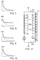
- FIGS. 7 - 10 teach the effect of the limiter shunt devices embodied in FIGS. 2 - 6, mounted in parallel with the field coil F1 and/or armature coil A1 as in FIG. 1.
- FIG. 7 is a RPM v. TORQUE (LOAD) graph showing the operational characteristics of a conventional series electric motor. Note that the speed rises indefinitely as the load is decreased and the speed decreases indefinitely as the load is increased.
- LID RPM v. TORQUE
- FIG. 8 is a RPM v. TORQUE graph showing the operational characteristics of a series electric motor having limiter shunt devices ZF and ZA mounted in parallel with the field coil F1 and armature coil A1, respectively, as shown in FIG. 1.
- the operational characteristics of a conventional series electric motor are superposed (see dotted line) for contrast.
- the armature appears to operate like a shunt electric motor. Note that the motor's top speed is limited under light load conditions and the motor's slowest speed is limited under heavy load conditions thereby protecting the transmission device and reducing noise level under light load conditions and increasing efficiency under heavy load conditions.
- the high and low limiting speed values may be preset by adjusting the Zener diode threshold voltages of the limiter shunt device circuits.
- FIG. 9 is an RPM v. TORQUE graph showing the operational characteristics of a series excitation motor with a limiter shunt device ZF mounted in parallel with the field coil F1 for effecting only the low-speed limiting function.
- the operational characteristics of a conventional series electric motor are superposed (see dotted line) for contrast. Note that the motor's top speed is not limited.
- current is shunted to the armature coil A1 through the limiter shunt device ZF only under heavy load and starting conditions when the speed of the motor decreases below the threshold speed as determined by the Zener diode ZD1 and ZD2 threshold voltages VZD1 and VZD2.
- FIG. 10 is an RPM v. TORQUE graph showing the operational characteristics of a series excitation motor with a limiter shunt device ZA mounted in parallel with the armature coil A1 for effecting only the high-speed limiting function. Note that the motor's lowest speed is not limited. Hence, when the load gets lighter and the armature's negative electromotive force (EMF) rises, some of the field coil F1 current will flow through the limiter shunt device ZA, thereby maintaining field magnetization to limit the top speed.
- the threshold at which current is shunted around the armature coil A1 through the limiter shunt device ZA is likewise determined by the Zener diode ZD1 and ZD2 threshold voltages VZD1 and VZD2.
- FIG. 11 is a circuit diagram of a variable (adjustable) type limiter shunt device circuit which enables easy modification of the preset voltage threshold value.
- This adjustable limiter shunt device comprises a field winding TF with a plurality of taps TF1-TFn.
- a discrete or integrated circuit series-chain of diodes ZM is tapped at each diode junction by a plurality of series taps TA1-TAn.
- An operating switch SWF connects one end of IC ZM to the field winding TF and to one terminal of the power supply
- an operating switch SWA connects the other end of IC ZM to the armature winding A and to the other terminal of the power supply.
- An operating switch SWO is connected between corresponding pairs of taps TF1-TFn and TA1-TAn for selectively connecting one of taps TF1-TFn with one of taps TA1-TAn to obtain the desired high and low speed limiting values.
- switch SWF will trigger the low-speed limiting operation of the limiter shunt device by placing a selected number of diodes of IC ZM in parallel with the field winding TF.
- switch SWA will trigger the high-speed limiting operation of the limiter shunt device by placing a selected number of diodes of IC ZM in parallel with the armature winding A.
Landscapes
- Engineering & Computer Science (AREA)
- Power Engineering (AREA)
- Control Of Direct Current Motors (AREA)
- Control Of Multiple Motors (AREA)
- Control Of Ac Motors In General (AREA)
Priority Applications (4)
| Application Number | Priority Date | Filing Date | Title |
|---|---|---|---|
| DK92309853T DK0594907T3 (da) | 1992-10-28 | 1992-10-28 | Hastighedsbegrænsende kredsløb til elektriske serie- eller compoundmotorer af universaltypen |
| EP19920309853 EP0594907B1 (en) | 1992-10-28 | 1992-10-28 | Speed limiting circuit for universal type series or compound electric motor |
| ES92309853T ES2099221T3 (es) | 1992-10-28 | 1992-10-28 | Circuito limitador de velocidad de un motor electrico serie o compound de tipo universal. |
| DE1992618603 DE69218603T2 (de) | 1992-10-28 | 1992-10-28 | Schaltungsanordnung zur Begrenzung der Geschwindigkeit eines Reihenschluss- oder Kompound-Elektromotors universeller Art |
Applications Claiming Priority (1)
| Application Number | Priority Date | Filing Date | Title |
|---|---|---|---|
| EP19920309853 EP0594907B1 (en) | 1992-10-28 | 1992-10-28 | Speed limiting circuit for universal type series or compound electric motor |
Publications (2)
| Publication Number | Publication Date |
|---|---|
| EP0594907A1 EP0594907A1 (en) | 1994-05-04 |
| EP0594907B1 true EP0594907B1 (en) | 1997-03-26 |
Family
ID=8211532
Family Applications (1)
| Application Number | Title | Priority Date | Filing Date |
|---|---|---|---|
| EP19920309853 Expired - Lifetime EP0594907B1 (en) | 1992-10-28 | 1992-10-28 | Speed limiting circuit for universal type series or compound electric motor |
Country Status (4)
| Country | Link |
|---|---|
| EP (1) | EP0594907B1 (da) |
| DE (1) | DE69218603T2 (da) |
| DK (1) | DK0594907T3 (da) |
| ES (1) | ES2099221T3 (da) |
Families Citing this family (5)
| Publication number | Priority date | Publication date | Assignee | Title |
|---|---|---|---|---|
| US6561444B1 (en) * | 1999-02-16 | 2003-05-13 | Kabushiki Kaisha Meiko Shokai | Shredder drive control device and method of drivingly controlling the shredder |
| GB0308012D0 (en) * | 2003-04-07 | 2003-05-14 | Bosch Gmbh Robert | Garden shredder |
| DE102016206415A1 (de) * | 2016-04-15 | 2017-10-19 | Stabilus Gmbh | Sicherheitsschaltung für einen Drehantrieb |
| US11530620B2 (en) | 2020-02-25 | 2022-12-20 | Siemens Mobility, Inc. | Overspeed protection for a motor of a gate crossing mechanism |
| CN113746401B (zh) * | 2021-10-09 | 2024-03-01 | 陕西航空电气有限责任公司 | 一种航空电励磁起动电机励磁回路拓扑结构及其励磁方法 |
Family Cites Families (3)
| Publication number | Priority date | Publication date | Assignee | Title |
|---|---|---|---|---|
| FR2174918A1 (da) * | 1972-03-03 | 1973-10-19 | Malte Manson Ab | |
| US5015928A (en) * | 1988-06-03 | 1991-05-14 | Yang Tai Her | Universal series motor with speed limiting circuit to protect the motor from overspeeding during relatively-small loads |
| EP0481773A1 (en) * | 1990-10-19 | 1992-04-22 | Tai-Her Yang | Improvement of series-excitation motor speed control circuit |
-
1992
- 1992-10-28 EP EP19920309853 patent/EP0594907B1/en not_active Expired - Lifetime
- 1992-10-28 ES ES92309853T patent/ES2099221T3/es not_active Expired - Lifetime
- 1992-10-28 DE DE1992618603 patent/DE69218603T2/de not_active Expired - Fee Related
- 1992-10-28 DK DK92309853T patent/DK0594907T3/da active
Also Published As
| Publication number | Publication date |
|---|---|
| EP0594907A1 (en) | 1994-05-04 |
| DK0594907T3 (da) | 1997-07-21 |
| ES2099221T3 (es) | 1997-05-16 |
| DE69218603T2 (de) | 1997-07-17 |
| DE69218603D1 (de) | 1997-04-30 |
Similar Documents
| Publication | Publication Date | Title |
|---|---|---|
| KR100488528B1 (ko) | 모터전원공급장치 | |
| US7368889B2 (en) | Motor control apparatus and control method thereof | |
| US4862053A (en) | Motor starting circuit | |
| US3222583A (en) | Control systems | |
| HK1003023A1 (en) | Control device for vehicle a.c. generator | |
| HK1003023B (en) | Control device for vehicle a.c. generator | |
| US4233549A (en) | Speed and torque control for fractional horsepower motors | |
| US3942090A (en) | Control process for operating a parallel-resonant circuit inverter that supplies an inductive charge, as well as the parallel-resonant circuit inverter operated by this method | |
| EP0594907B1 (en) | Speed limiting circuit for universal type series or compound electric motor | |
| US6556460B2 (en) | Method for controlling a vehicle provided with an electric power converter | |
| US5254913A (en) | Speed limiting circuit for universal type series or compound electric motor | |
| EP0181938A1 (en) | Controller for an induction motor | |
| US5015928A (en) | Universal series motor with speed limiting circuit to protect the motor from overspeeding during relatively-small loads | |
| US3684937A (en) | Reversible d. c. motor system | |
| EP0560089A1 (en) | An electric drive system in lift trucks | |
| WO2016085862A1 (en) | Motor braking system and method for power tools | |
| US4568871A (en) | Balancing system for limiting voltage imbalance across series-connected capacitors | |
| EP0107351B2 (en) | Synchronous motor control | |
| EP0594906B1 (en) | Governor circuit for universal series (or compound) motor | |
| US4634942A (en) | Apparatus for controlling electric cars | |
| US4482946A (en) | Hybrid inverter | |
| US5569992A (en) | DC shunt (or compound) motor and its related circuit with controllable dynamic characteristics | |
| US4179645A (en) | Circuit for driving and braking a speed-controlled direct current motor | |
| JPH05292794A (ja) | 万能式直列励磁モータの高低速度制限装置 | |
| JP2742800B2 (ja) | 誘導電動機の巻線切換装置 |
Legal Events
| Date | Code | Title | Description |
|---|---|---|---|
| PUAI | Public reference made under article 153(3) epc to a published international application that has entered the european phase |
Free format text: ORIGINAL CODE: 0009012 |
|
| AK | Designated contracting states |
Kind code of ref document: A1 Designated state(s): DE DK ES FR GB IT NL |
|
| 17P | Request for examination filed |
Effective date: 19941101 |
|
| 17Q | First examination report despatched |
Effective date: 19950811 |
|
| GRAG | Despatch of communication of intention to grant |
Free format text: ORIGINAL CODE: EPIDOS AGRA |
|
| RAP1 | Party data changed (applicant data changed or rights of an application transferred) |
Owner name: YANG, TAI-HER |
|
| GRAH | Despatch of communication of intention to grant a patent |
Free format text: ORIGINAL CODE: EPIDOS IGRA |
|
| GRAH | Despatch of communication of intention to grant a patent |
Free format text: ORIGINAL CODE: EPIDOS IGRA |
|
| GRAA | (expected) grant |
Free format text: ORIGINAL CODE: 0009210 |
|
| AK | Designated contracting states |
Kind code of ref document: B1 Designated state(s): DE DK ES FR GB IT NL |
|
| ITF | It: translation for a ep patent filed | ||
| REF | Corresponds to: |
Ref document number: 69218603 Country of ref document: DE Date of ref document: 19970430 |
|
| REG | Reference to a national code |
Ref country code: ES Ref legal event code: FG2A Ref document number: 2099221 Country of ref document: ES Kind code of ref document: T3 |
|
| ET | Fr: translation filed | ||
| REG | Reference to a national code |
Ref country code: DK Ref legal event code: T3 |
|
| PGFP | Annual fee paid to national office [announced via postgrant information from national office to epo] |
Ref country code: DK Payment date: 19971030 Year of fee payment: 6 |
|
| PLBE | No opposition filed within time limit |
Free format text: ORIGINAL CODE: 0009261 |
|
| 26N | No opposition filed | ||
| PG25 | Lapsed in a contracting state [announced via postgrant information from national office to epo] |
Ref country code: DK Free format text: LAPSE BECAUSE OF NON-PAYMENT OF DUE FEES Effective date: 19981028 |
|
| PGFP | Annual fee paid to national office [announced via postgrant information from national office to epo] |
Ref country code: GB Payment date: 20000411 Year of fee payment: 8 |
|
| PGFP | Annual fee paid to national office [announced via postgrant information from national office to epo] |
Ref country code: NL Payment date: 20000417 Year of fee payment: 8 |
|
| PGFP | Annual fee paid to national office [announced via postgrant information from national office to epo] |
Ref country code: DE Payment date: 20000420 Year of fee payment: 8 |
|
| PGFP | Annual fee paid to national office [announced via postgrant information from national office to epo] |
Ref country code: ES Payment date: 20000427 Year of fee payment: 8 |
|
| PGFP | Annual fee paid to national office [announced via postgrant information from national office to epo] |
Ref country code: FR Payment date: 20000428 Year of fee payment: 8 |
|
| REG | Reference to a national code |
Ref country code: DK Ref legal event code: EBP |
|
| PG25 | Lapsed in a contracting state [announced via postgrant information from national office to epo] |
Ref country code: GB Free format text: LAPSE BECAUSE OF NON-PAYMENT OF DUE FEES Effective date: 20001028 |
|
| PG25 | Lapsed in a contracting state [announced via postgrant information from national office to epo] |
Ref country code: ES Free format text: LAPSE BECAUSE OF NON-PAYMENT OF DUE FEES Effective date: 20001029 |
|
| PG25 | Lapsed in a contracting state [announced via postgrant information from national office to epo] |
Ref country code: NL Free format text: LAPSE BECAUSE OF NON-PAYMENT OF DUE FEES Effective date: 20010501 |
|
| GBPC | Gb: european patent ceased through non-payment of renewal fee |
Effective date: 20001028 |
|
| PG25 | Lapsed in a contracting state [announced via postgrant information from national office to epo] |
Ref country code: FR Free format text: LAPSE BECAUSE OF NON-PAYMENT OF DUE FEES Effective date: 20010629 |
|
| NLV4 | Nl: lapsed or anulled due to non-payment of the annual fee |
Effective date: 20010501 |
|
| PG25 | Lapsed in a contracting state [announced via postgrant information from national office to epo] |
Ref country code: DE Free format text: LAPSE BECAUSE OF NON-PAYMENT OF DUE FEES Effective date: 20010703 |
|
| REG | Reference to a national code |
Ref country code: FR Ref legal event code: ST |
|
| REG | Reference to a national code |
Ref country code: ES Ref legal event code: FD2A Effective date: 20011113 |
|
| PG25 | Lapsed in a contracting state [announced via postgrant information from national office to epo] |
Ref country code: IT Free format text: LAPSE BECAUSE OF NON-PAYMENT OF DUE FEES;WARNING: LAPSES OF ITALIAN PATENTS WITH EFFECTIVE DATE BEFORE 2007 MAY HAVE OCCURRED AT ANY TIME BEFORE 2007. THE CORRECT EFFECTIVE DATE MAY BE DIFFERENT FROM THE ONE RECORDED. Effective date: 20051028 |