EP0594797B1 - Procede pour la surveillance d'une zone - Google Patents
Procede pour la surveillance d'une zone Download PDFInfo
- Publication number
- EP0594797B1 EP0594797B1 EP93902244A EP93902244A EP0594797B1 EP 0594797 B1 EP0594797 B1 EP 0594797B1 EP 93902244 A EP93902244 A EP 93902244A EP 93902244 A EP93902244 A EP 93902244A EP 0594797 B1 EP0594797 B1 EP 0594797B1
- Authority
- EP
- European Patent Office
- Prior art keywords
- area
- radar
- points
- point
- cell
- Prior art date
- Legal status (The legal status is an assumption and is not a legal conclusion. Google has not performed a legal analysis and makes no representation as to the accuracy of the status listed.)
- Expired - Lifetime
Links
Images


Classifications
-
- G—PHYSICS
- G01—MEASURING; TESTING
- G01S—RADIO DIRECTION-FINDING; RADIO NAVIGATION; DETERMINING DISTANCE OR VELOCITY BY USE OF RADIO WAVES; LOCATING OR PRESENCE-DETECTING BY USE OF THE REFLECTION OR RERADIATION OF RADIO WAVES; ANALOGOUS ARRANGEMENTS USING OTHER WAVES
- G01S13/00—Systems using the reflection or reradiation of radio waves, e.g. radar systems; Analogous systems using reflection or reradiation of waves whose nature or wavelength is irrelevant or unspecified
- G01S13/87—Combinations of radar systems, e.g. primary radar and secondary radar
-
- G—PHYSICS
- G01—MEASURING; TESTING
- G01S—RADIO DIRECTION-FINDING; RADIO NAVIGATION; DETERMINING DISTANCE OR VELOCITY BY USE OF RADIO WAVES; LOCATING OR PRESENCE-DETECTING BY USE OF THE REFLECTION OR RERADIATION OF RADIO WAVES; ANALOGOUS ARRANGEMENTS USING OTHER WAVES
- G01S13/00—Systems using the reflection or reradiation of radio waves, e.g. radar systems; Analogous systems using reflection or reradiation of waves whose nature or wavelength is irrelevant or unspecified
- G01S13/02—Systems using reflection of radio waves, e.g. primary radar systems; Analogous systems
- G01S13/04—Systems determining presence of a target
Definitions
- the invention relates to a method for monitoring an area according to the preamble of claim 1. Such a method is known from GB-A-2 165 414.
- the invention particularly relates to the surveillance of an area in which at least one non-cooperative (radar) target is present.
- a destination has no so-called transponder and / or no navigation system, the navigation result of which can be queried by a fixed (radar) transmission / reception system.
- Such an area can be, for example, a so-called regional airfield, which is handled according to visual flight rules.
- the area can e.g. B. also be an apron belonging to a major airport, on the z. B. next to the resting or moving aircraft also stationary or moving vehicles, e.g. B. feeder buses and / or supply vehicles must be monitored.
- the area can e.g. B. also a shipping route, e.g. B. a river and / or a canal or a port facility.
- the invention is therefore based on the object of specifying a generic method which enables complete, low-warpage, accurate and, as far as possible, location-independent location, classification and tracking of stationary and / or moving objects (targets) in the area to be monitored.
- the invention is also based on the object of specifying an inexpensive and reliable method.
- a first advantage of the invention consists in the fact that in an area to be monitored, a uniformly accurate and improved location and classification with a combination of high-resolution, inexpensive and spatially small radar sensors of limited range is possible.
- a second advantage consists in the fact that a positioning of the radar systems and / or radar sensors that is adapted to the area to be monitored is possible and thus a complete and shadow-free monitoring.
- a third advantage is that range-limited semiconductor transmitters, which are inexpensive, can be used for radar systems (radar sensors).
- a fourth advantage is that the area to be monitored is divided into small areas, preferably adjacent triangles. This enables, on the one hand, an inexpensive expansion of the area to be monitored and, on the other hand, sufficient monitoring if one of the radar systems (radar sensors) fails as a result of a defect or maintenance work.
- FIG. 1 shows the area 1 to be monitored in the form of two parallel strips which are underlaid with a gray dot matrix.
- the parallel strips are also connected by an oblique strip.
- Such a representation can e.g. B. correspond to a partial area of an airport, for example a runway section to be monitored and / or runways or taxiways on the so-called apron.
- the display can also correspond to a canal or highway system to be monitored, which is located in a topographically confusing area.
- the representation can correspond to a canal or highway system, between which there is a hilly area and / or a dense development.
- Such an area to be monitored is now covered with a dot matrix (large black dots) in the manner shown.
- these points 2 have a distance which is in a range of preferably 0.3 km to 3 km.
- the points 2 are connected with lines, so that seamlessly adjoining polygonal surfaces 3 are formed, which are also called cells. These surfaces 3 are preferably designed as triangles.
- other areas (cells) are also possible, e.g. B. squares, pentagons or hexagons and / or a mixture of these.
- the points 3 (corner points) belonging to an area 3 (cell) are chosen in accordance with the topographical conditions so that the associated area or areas, e.g. B.
- Points 2 can e.g. B. on a hill, a mast, a building and / or - on flat terrain - z. B. directly next to the runway to be monitored or the canal or highway system.
- a radar system which is also called a radar sensor, is now arranged at each of the points 2.
- a radar system has a short range, which extends to the nearest point, which will be explained in more detail below.
- Such radar systems contain e.g. B. a rapidly rotating, e.g. B. with 60 rpm (revolutions per minute), transmitting / receiving antenna, which is designed as a reflector antenna and has a maximum diameter of approximately 0.5 m.
- Such an antenna is advantageously protected by a radome.
- a CW range continuous wave mode, continuous wave mode
- the radar systems preferably operate in the MMW range (millimeter wave range) and have a transmission power which is preferably in the range from 50 mW to 500 mW.
- Such transmitters can be produced inexpensively using reliable semiconductor technology.
- This large number of radar systems is controlled and / or monitored by a control center that is far away, e.g. B. a few kilometers from the area to be monitored. Such a center can also be used to monitor several such areas at the same time in a cost-effective manner.
- the one between the head office and the individual radar systems Necessary (data) communication takes place via suitable (data) transmission links, e.g. B. electrical cables, optical fibers and / or radio links, which preferably also work in the millimeter wave range. From the head office is z. B. the rotation of the radar antennas and / or the emitted millimeter waves so synchronized that within a surface 3 (cell) a common signal processing of the signals received by the radar antenna can take place.
- an evaluation unit which preferably contains a digitally operating computing system, for the signals received by the radar systems.
- a digitally operating computing system for the signals received by the radar systems.
- These can be evaluated in a variety of ways, depending on the required requirements. For example, it is possible to evaluate the received signals from an individual radar system and / or the radar systems belonging to an area 3 (cell) and / or the radar systems belonging to selected areas and / or all radar systems. In this way, e.g. B. (Radar) images can be displayed with different spatial resolutions.
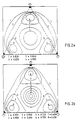
- FIG. 2 to 4 selected advantageous detection properties for a surface 3 (cell), which is designed as a triangular surface, are shown.
- the mushroom-shaped radar systems are located at the corner points of a triangle, which is also called the basic cell.
- FIG. 2a shows curves of constant positional accuracy in the area of the basic cells shown in broken lines for a moving or non-moving target.
- the specified so-called CEP values are standardized to the distance measurement accuracy of the at the corner points located radar systems. It can be seen that the position accuracy is advantageously almost independent of location. The differences resulting from curves 1 to 4 are negligible in practical use.
- FIG. 2b is the representation corresponding to FIG. 2a belonging ellipticity (axis ratio) of the error ellipses is shown. It can be seen that a possibly inaccurate position determination of a target is only present in the immediate vicinity (curves 8) of the radar systems.
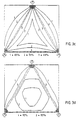
- the probability of resolution P res for a single radar system is shown. This is located on the left corner of the basic cell. The distance between the corner points is approximately 1 km.
- the (single) radar systems each have a range resolution of 2 m and an azimuth resolution of 2 °.
- FIG. 3c shows a representation corresponding to FIG. 3a, but with the difference that a radar system according to FIG. 3a is present.
- FIG. 4a, 4b show the achievable accuracy of determining a speed vector for a target within a basic cell in accordance with the representations of FIG. 3c, 3d.
- FIG. 4a shows curves of constant accuracy of the speed vector in the area of the basic cell.
- the CEP information used is standardized to the Doppler measurement accuracy of the individual radar systems located at the corner points. It can be seen that the velocity vector can be determined with an accuracy which is almost constant within the Magnolia cells.
- FIG. 4b shows the FIG. 4a belonging ellipticity of the error ellipses.
- the invention is not limited to the exemplary embodiments described, but can be applied to others in a variety of ways. For example, reliable monitoring of a national border in the case of difficult topography, e.g. B. in the mountains, possible. Furthermore, reliable monitoring of ports, rivers, bays and / or straits is possible.
Landscapes
- Engineering & Computer Science (AREA)
- Radar, Positioning & Navigation (AREA)
- Remote Sensing (AREA)
- Computer Networks & Wireless Communication (AREA)
- Physics & Mathematics (AREA)
- General Physics & Mathematics (AREA)
- Radar Systems Or Details Thereof (AREA)
- Medicines That Contain Protein Lipid Enzymes And Other Medicines (AREA)
Abstract
Claims (8)
- Procédé pour la surveillance d'une zone, dans laquelle se trouve au moins une cible non coopérative, à l'aide d'une installation radar, selon lequel- on superpose à la zone à surveiller une matrice de points;- on place à chaque point de cette matrice une installation radar fonctionnant en régime continu;- on choisit l'emplacement des points en fonction de la topographie de la zone;caractérisé en ce que- on choisit au moins trois points pour constituer les angles d'une surface (cellule) polygonale correspondante;- on interconnecte au moins les installations radar se trouvant aux angles de la surface en un réseau à travers une unité d'exploitation et on effectue, à l'intérieur d'une surface, un traitement de signaux commun en vue de la détection des signaux reçus des antennes radar, et- on choisit les distances entre les points ainsi que les caractéristiques de fonctionnement en fonction des propriétés de détection requises sur la surface.
- Procédé selon la revendication 1, caractérisé en ce que l'on choisit l'emplacement des points d'une surface (cellule), de manière qu'une vue directe existe entre eux et que, à partir de chaque point, la surface (cellule) coordonnée puisse être surveillée sans masquage ou occultation.
- Procédé selon la revendication 1 ou 2, caractérisé en ce que- on place au moins deux surfaces (cellules) l'une à côté de l'autre, sans lacunes, de manière qu'elles possèdent une ligne de délimitation commune;- on utilise au moins un point comme un angle des deux surfaces; et- on surveille les deux surfaces, ou un plus grand nombre de surfaces (cellules) au moyen de l'installation radar placée à cet angle.
- Procédé selon une des revendications précédentes, caractérisé en ce que les installations radar se trouvant aux différents points, possèdent chacune une portée allant tout au plus jusqu'au point voisin.
- Procédé selon une des revendications précédentes, caractérisé en ce que la portée d'une installation radar est de l'ordre de 0,3 km à 3 km et que l'on choisit la portée en fonction de l'espacement des points voisins.
- Procédé selon une des revendications précédentes, caractérisé en ce que- on place sur les angles d'au moins une surface (cellule) des installations radar à modulation en régime continu;- les installations radar émettent un rayonnement à polarisation circulaire dans la gamme millimétrique; et- on effectue une exploitation polarimétrique de canaux de réception orthogonaux.
- Procédé selon une des revendications précédentes, caractérisé en ce que, au moins pour chaque surface (cellule), on exploite dans une unité centrale d'exploitation les signaux reçus des installations radar se trouvant aux angles de la surface.
- Procédé selon une des revendications précédentes, caractérisé en ce que l'on détermine dans l'unité d'exploitation au moins la position et la vitesse vectorielle des cibles détectées et que l'on classe les cibles.
Applications Claiming Priority (3)
| Application Number | Priority Date | Filing Date | Title |
|---|---|---|---|
| DE4216391 | 1992-05-18 | ||
| DE4216391 | 1992-05-18 | ||
| PCT/EP1993/000154 WO1993023768A1 (fr) | 1992-05-18 | 1993-01-23 | Procede pour la surveillance d'une zone |
Publications (2)
| Publication Number | Publication Date |
|---|---|
| EP0594797A1 EP0594797A1 (fr) | 1994-05-04 |
| EP0594797B1 true EP0594797B1 (fr) | 1996-11-13 |
Family
ID=6459153
Family Applications (1)
| Application Number | Title | Priority Date | Filing Date |
|---|---|---|---|
| EP93902244A Expired - Lifetime EP0594797B1 (fr) | 1992-05-18 | 1993-01-23 | Procede pour la surveillance d'une zone |
Country Status (5)
| Country | Link |
|---|---|
| US (1) | US5461384A (fr) |
| EP (1) | EP0594797B1 (fr) |
| CA (1) | CA2113454A1 (fr) |
| DE (1) | DE59304473D1 (fr) |
| WO (1) | WO1993023768A1 (fr) |
Families Citing this family (10)
| Publication number | Priority date | Publication date | Assignee | Title |
|---|---|---|---|---|
| US5920318A (en) * | 1997-03-26 | 1999-07-06 | Northrop Grumman Corporation | Method and apparatus for localizing an object within a sector of a physical surface |
| DE102004062023B4 (de) * | 2004-12-23 | 2021-12-23 | Robert Bosch Gmbh | Radarsystem zur Überwachung von Zielen in verschiedenen Entfernungsbereichen |
| EP1790994A1 (fr) * | 2005-11-23 | 2007-05-30 | Ascom (Schweiz) AG | Procédé de déclenchement d'un événement en réponse à un mouvement, système avec un capteur de mouvement et capteur de mouvement |
| US20110221624A1 (en) * | 2007-12-05 | 2011-09-15 | Sensys Networks, Inc | Apparatus and Method Using a Radar in a Wireless and/or Wireline Sensor Node and Operating Radar In the Ground to Detect and Count Vehicles in Roadway, Parking Lot and Airport Applications |
| FR2942884B1 (fr) | 2009-03-09 | 2011-04-01 | Onera (Off Nat Aerospatiale) | Systeme de radar multistatique de surveillance aeroportuaire |
| AU2012325362B2 (en) | 2011-10-19 | 2014-08-07 | Balu Subramanya | Directional speed and distance sensor |
| US8264401B1 (en) | 2011-12-29 | 2012-09-11 | Sensys Networks, Inc. | Micro-radar, micro-radar sensor nodes, networks and systems |
| US11004337B2 (en) | 2012-12-28 | 2021-05-11 | Balu Subramanya | Advanced parking management system |
| RU2596851C1 (ru) * | 2015-07-22 | 2016-09-10 | Акционерное общество "НИИ измерительных приборов - Новосибирский завод имени Коминтерна" (АО "НПО НИИИП-НЗиК") | Способ радиолокационного обзора пространства (варианты) |
| WO2018226253A1 (fr) | 2016-12-16 | 2018-12-13 | The Government Of The United States Of America As Represented By The Secretary Of The Navy | Système de navigation assisté par le terrain et des ondes millimétriques |
Family Cites Families (3)
| Publication number | Priority date | Publication date | Assignee | Title |
|---|---|---|---|---|
| GB2165414B (en) * | 1984-10-03 | 1988-01-13 | Standard Telephones Cables Plc | Runway occupancy warning system |
| GB2215932A (en) * | 1988-03-26 | 1989-09-27 | Gec Traffic Automation | Radio position finding system |
| NL9001599A (nl) * | 1990-07-13 | 1992-02-03 | Frans Herman De Haan | Inrichting voor het lokaliseren en identificeren van antwoorders. |
-
1993
- 1993-01-23 CA CA002113454A patent/CA2113454A1/fr not_active Abandoned
- 1993-01-23 EP EP93902244A patent/EP0594797B1/fr not_active Expired - Lifetime
- 1993-01-23 DE DE59304473T patent/DE59304473D1/de not_active Expired - Fee Related
- 1993-01-23 WO PCT/EP1993/000154 patent/WO1993023768A1/fr active IP Right Grant
-
1994
- 1994-01-05 US US08/175,345 patent/US5461384A/en not_active Expired - Fee Related
Also Published As
| Publication number | Publication date |
|---|---|
| US5461384A (en) | 1995-10-24 |
| CA2113454A1 (fr) | 1993-11-25 |
| WO1993023768A1 (fr) | 1993-11-25 |
| DE59304473D1 (de) | 1996-12-19 |
| EP0594797A1 (fr) | 1994-05-04 |
Similar Documents
| Publication | Publication Date | Title |
|---|---|---|
| US5663720A (en) | Method and system for regional traffic monitoring | |
| US5400031A (en) | Airport surface vehicle identification system and method | |
| CA1139410A (fr) | Systeme de controle aeroportuaire | |
| EP0550073B1 (fr) | Système de localisation d'objets et d'obstacles multiples et de détection et détermination de la condition de roulis d'objets en mouvement, comme avions, véhicules terrestres, etc. | |
| DE102011010846B4 (de) | Verfahren und System zur sichtverbindungsunabhängigen Datenübertragung | |
| EP0594797B1 (fr) | Procede pour la surveillance d'une zone | |
| DE102008014330A1 (de) | Hindernis-Erkennungssystem insbesondere für ein Antikollisions-System | |
| DE2364086A1 (de) | Sekundaerradar-verfahren und einrichtung zur feststellung eines in der naehe befindlichen fahrzeugs | |
| EP3857256B1 (fr) | Procédé de détection d'usagers de la voie publique | |
| WO2009156337A1 (fr) | Procédé et dispositif de détermination passive de paramètres cibles | |
| EP0505827A1 (fr) | Système de radar secondaire | |
| DE102013004463B4 (de) | Vorrichtung und Verfahren zur Detektion von Flugobjekten im Umkreis von Windkraftanlagen | |
| DE19910715C2 (de) | Verfahren zum autonomen Führen von Roboterfahrzeugen in Hallen sowie Radarstation zur Durchführung des Verfahrens | |
| WO2004075139A1 (fr) | Systeme de surveillance du terrain d'un aeroport | |
| EP1153314B1 (fr) | Procede et dispositif pour determiner une position | |
| DE19902008C2 (de) | Anordnung zur interferometrischen Radarmessung nach dem ROSAR-Prinzip | |
| Nohara et al. | Affordable avian radar surveillance systems for natural resource management and BASH applications | |
| DE4315863A1 (de) | Verfahren zur Überwachung eines Gebietes | |
| EP0273326A2 (fr) | Système d'aide à l'atterrissage pour avions comportant leur propre radar de bord | |
| WO2008040342A1 (fr) | Système radar doté d'un seul capteur pour balayer l'environnement d'un véhicule à moteur | |
| DE2461945A1 (de) | Gelaendeebenen-winkelreflektor fuer die navigation und die fernanzeige sowie dessen anwendung | |
| DE19522464A1 (de) | Radarsystem zur Überwachung eines vorgegebenen Gebiets | |
| EP3737969A1 (fr) | Procédé de commande de trafic, capteur radar et réseau de capteurs radars | |
| EP0738900B1 (fr) | Procédé d'aide à l'atterrissage pour des avions | |
| DE4226943C2 (de) | Verfahren zur Erfassung eines Verkehrsteilnehmers |
Legal Events
| Date | Code | Title | Description |
|---|---|---|---|
| PUAI | Public reference made under article 153(3) epc to a published international application that has entered the european phase |
Free format text: ORIGINAL CODE: 0009012 |
|
| 17P | Request for examination filed |
Effective date: 19931224 |
|
| AK | Designated contracting states |
Kind code of ref document: A1 Designated state(s): DE FR GB IT |
|
| RAP1 | Party data changed (applicant data changed or rights of an application transferred) |
Owner name: DAIMLER-BENZ AEROSPACE AKTIENGESELLSCHAFT |
|
| GRAG | Despatch of communication of intention to grant |
Free format text: ORIGINAL CODE: EPIDOS AGRA |
|
| 17Q | First examination report despatched |
Effective date: 19960305 |
|
| GRAH | Despatch of communication of intention to grant a patent |
Free format text: ORIGINAL CODE: EPIDOS IGRA |
|
| GRAH | Despatch of communication of intention to grant a patent |
Free format text: ORIGINAL CODE: EPIDOS IGRA |
|
| GRAA | (expected) grant |
Free format text: ORIGINAL CODE: 0009210 |
|
| ITF | It: translation for a ep patent filed |
Owner name: BARZANO' E ZANARDO MILANO S.P.A. |
|
| AK | Designated contracting states |
Kind code of ref document: B1 Designated state(s): DE FR GB IT |
|
| REF | Corresponds to: |
Ref document number: 59304473 Country of ref document: DE Date of ref document: 19961219 |
|
| ET | Fr: translation filed | ||
| GBT | Gb: translation of ep patent filed (gb section 77(6)(a)/1977) |
Effective date: 19970123 |
|
| PLBE | No opposition filed within time limit |
Free format text: ORIGINAL CODE: 0009261 |
|
| STAA | Information on the status of an ep patent application or granted ep patent |
Free format text: STATUS: NO OPPOSITION FILED WITHIN TIME LIMIT |
|
| 26N | No opposition filed | ||
| PGFP | Annual fee paid to national office [announced via postgrant information from national office to epo] |
Ref country code: GB Payment date: 20011214 Year of fee payment: 10 |
|
| PGFP | Annual fee paid to national office [announced via postgrant information from national office to epo] |
Ref country code: DE Payment date: 20011217 Year of fee payment: 10 |
|
| PGFP | Annual fee paid to national office [announced via postgrant information from national office to epo] |
Ref country code: FR Payment date: 20011226 Year of fee payment: 10 |
|
| REG | Reference to a national code |
Ref country code: GB Ref legal event code: IF02 |
|
| PG25 | Lapsed in a contracting state [announced via postgrant information from national office to epo] |
Ref country code: GB Free format text: LAPSE BECAUSE OF NON-PAYMENT OF DUE FEES Effective date: 20030123 |
|
| PG25 | Lapsed in a contracting state [announced via postgrant information from national office to epo] |
Ref country code: DE Free format text: LAPSE BECAUSE OF NON-PAYMENT OF DUE FEES Effective date: 20030801 |
|
| GBPC | Gb: european patent ceased through non-payment of renewal fee | ||
| PG25 | Lapsed in a contracting state [announced via postgrant information from national office to epo] |
Ref country code: FR Free format text: LAPSE BECAUSE OF NON-PAYMENT OF DUE FEES Effective date: 20030930 |
|
| REG | Reference to a national code |
Ref country code: FR Ref legal event code: ST |
|
| PG25 | Lapsed in a contracting state [announced via postgrant information from national office to epo] |
Ref country code: IT Free format text: LAPSE BECAUSE OF NON-PAYMENT OF DUE FEES;WARNING: LAPSES OF ITALIAN PATENTS WITH EFFECTIVE DATE BEFORE 2007 MAY HAVE OCCURRED AT ANY TIME BEFORE 2007. THE CORRECT EFFECTIVE DATE MAY BE DIFFERENT FROM THE ONE RECORDED. Effective date: 20050123 |