EP0594194B1 - A recording and reproducing medium and a recording and reproducing apparatus - Google Patents
A recording and reproducing medium and a recording and reproducing apparatus Download PDFInfo
- Publication number
- EP0594194B1 EP0594194B1 EP93117153A EP93117153A EP0594194B1 EP 0594194 B1 EP0594194 B1 EP 0594194B1 EP 93117153 A EP93117153 A EP 93117153A EP 93117153 A EP93117153 A EP 93117153A EP 0594194 B1 EP0594194 B1 EP 0594194B1
- Authority
- EP
- European Patent Office
- Prior art keywords
- recording
- reproducing
- layer
- medium according
- reproducing medium
- Prior art date
- Legal status (The legal status is an assumption and is not a legal conclusion. Google has not performed a legal analysis and makes no representation as to the accuracy of the status listed.)
- Expired - Lifetime
Links
Images




Classifications
-
- G—PHYSICS
- G11—INFORMATION STORAGE
- G11B—INFORMATION STORAGE BASED ON RELATIVE MOVEMENT BETWEEN RECORD CARRIER AND TRANSDUCER
- G11B7/00—Recording or reproducing by optical means, e.g. recording using a thermal beam of optical radiation by modifying optical properties or the physical structure, reproducing using an optical beam at lower power by sensing optical properties; Record carriers therefor
- G11B7/24—Record carriers characterised by shape, structure or physical properties, or by the selection of the material
- G11B7/241—Record carriers characterised by shape, structure or physical properties, or by the selection of the material characterised by the selection of the material
- G11B7/242—Record carriers characterised by shape, structure or physical properties, or by the selection of the material characterised by the selection of the material of recording layers
-
- G—PHYSICS
- G11—INFORMATION STORAGE
- G11B—INFORMATION STORAGE BASED ON RELATIVE MOVEMENT BETWEEN RECORD CARRIER AND TRANSDUCER
- G11B7/00—Recording or reproducing by optical means, e.g. recording using a thermal beam of optical radiation by modifying optical properties or the physical structure, reproducing using an optical beam at lower power by sensing optical properties; Record carriers therefor
- G11B7/24—Record carriers characterised by shape, structure or physical properties, or by the selection of the material
-
- G—PHYSICS
- G11—INFORMATION STORAGE
- G11B—INFORMATION STORAGE BASED ON RELATIVE MOVEMENT BETWEEN RECORD CARRIER AND TRANSDUCER
- G11B7/00—Recording or reproducing by optical means, e.g. recording using a thermal beam of optical radiation by modifying optical properties or the physical structure, reproducing using an optical beam at lower power by sensing optical properties; Record carriers therefor
- G11B7/004—Recording, reproducing or erasing methods; Read, write or erase circuits therefor
-
- G—PHYSICS
- G11—INFORMATION STORAGE
- G11B—INFORMATION STORAGE BASED ON RELATIVE MOVEMENT BETWEEN RECORD CARRIER AND TRANSDUCER
- G11B7/00—Recording or reproducing by optical means, e.g. recording using a thermal beam of optical radiation by modifying optical properties or the physical structure, reproducing using an optical beam at lower power by sensing optical properties; Record carriers therefor
- G11B7/24—Record carriers characterised by shape, structure or physical properties, or by the selection of the material
- G11B7/241—Record carriers characterised by shape, structure or physical properties, or by the selection of the material characterised by the selection of the material
- G11B7/252—Record carriers characterised by shape, structure or physical properties, or by the selection of the material characterised by the selection of the material of layers other than recording layers
- G11B7/257—Record carriers characterised by shape, structure or physical properties, or by the selection of the material characterised by the selection of the material of layers other than recording layers of layers having properties involved in recording or reproduction, e.g. optical interference layers or sensitising layers or dielectric layers, which are protecting the recording layers
- G11B7/2578—Record carriers characterised by shape, structure or physical properties, or by the selection of the material characterised by the selection of the material of layers other than recording layers of layers having properties involved in recording or reproduction, e.g. optical interference layers or sensitising layers or dielectric layers, which are protecting the recording layers consisting essentially of inorganic materials
-
- G—PHYSICS
- G11—INFORMATION STORAGE
- G11B—INFORMATION STORAGE BASED ON RELATIVE MOVEMENT BETWEEN RECORD CARRIER AND TRANSDUCER
- G11B7/00—Recording or reproducing by optical means, e.g. recording using a thermal beam of optical radiation by modifying optical properties or the physical structure, reproducing using an optical beam at lower power by sensing optical properties; Record carriers therefor
- G11B7/24—Record carriers characterised by shape, structure or physical properties, or by the selection of the material
- G11B7/241—Record carriers characterised by shape, structure or physical properties, or by the selection of the material characterised by the selection of the material
- G11B7/252—Record carriers characterised by shape, structure or physical properties, or by the selection of the material characterised by the selection of the material of layers other than recording layers
- G11B7/257—Record carriers characterised by shape, structure or physical properties, or by the selection of the material characterised by the selection of the material of layers other than recording layers of layers having properties involved in recording or reproduction, e.g. optical interference layers or sensitising layers or dielectric layers, which are protecting the recording layers
- G11B2007/25705—Record carriers characterised by shape, structure or physical properties, or by the selection of the material characterised by the selection of the material of layers other than recording layers of layers having properties involved in recording or reproduction, e.g. optical interference layers or sensitising layers or dielectric layers, which are protecting the recording layers consisting essentially of inorganic materials
- G11B2007/25706—Record carriers characterised by shape, structure or physical properties, or by the selection of the material characterised by the selection of the material of layers other than recording layers of layers having properties involved in recording or reproduction, e.g. optical interference layers or sensitising layers or dielectric layers, which are protecting the recording layers consisting essentially of inorganic materials containing transition metal elements (Zn, Fe, Co, Ni, Pt)
-
- G—PHYSICS
- G11—INFORMATION STORAGE
- G11B—INFORMATION STORAGE BASED ON RELATIVE MOVEMENT BETWEEN RECORD CARRIER AND TRANSDUCER
- G11B7/00—Recording or reproducing by optical means, e.g. recording using a thermal beam of optical radiation by modifying optical properties or the physical structure, reproducing using an optical beam at lower power by sensing optical properties; Record carriers therefor
- G11B7/24—Record carriers characterised by shape, structure or physical properties, or by the selection of the material
- G11B7/241—Record carriers characterised by shape, structure or physical properties, or by the selection of the material characterised by the selection of the material
- G11B7/252—Record carriers characterised by shape, structure or physical properties, or by the selection of the material characterised by the selection of the material of layers other than recording layers
- G11B7/257—Record carriers characterised by shape, structure or physical properties, or by the selection of the material characterised by the selection of the material of layers other than recording layers of layers having properties involved in recording or reproduction, e.g. optical interference layers or sensitising layers or dielectric layers, which are protecting the recording layers
- G11B2007/25705—Record carriers characterised by shape, structure or physical properties, or by the selection of the material characterised by the selection of the material of layers other than recording layers of layers having properties involved in recording or reproduction, e.g. optical interference layers or sensitising layers or dielectric layers, which are protecting the recording layers consisting essentially of inorganic materials
- G11B2007/25708—Record carriers characterised by shape, structure or physical properties, or by the selection of the material characterised by the selection of the material of layers other than recording layers of layers having properties involved in recording or reproduction, e.g. optical interference layers or sensitising layers or dielectric layers, which are protecting the recording layers consisting essentially of inorganic materials containing group 13 elements (B, Al, Ga)
-
- Y—GENERAL TAGGING OF NEW TECHNOLOGICAL DEVELOPMENTS; GENERAL TAGGING OF CROSS-SECTIONAL TECHNOLOGIES SPANNING OVER SEVERAL SECTIONS OF THE IPC; TECHNICAL SUBJECTS COVERED BY FORMER USPC CROSS-REFERENCE ART COLLECTIONS [XRACs] AND DIGESTS
- Y10—TECHNICAL SUBJECTS COVERED BY FORMER USPC
- Y10S—TECHNICAL SUBJECTS COVERED BY FORMER USPC CROSS-REFERENCE ART COLLECTIONS [XRACs] AND DIGESTS
- Y10S428/00—Stock material or miscellaneous articles
- Y10S428/913—Material designed to be responsive to temperature, light, moisture
-
- Y—GENERAL TAGGING OF NEW TECHNOLOGICAL DEVELOPMENTS; GENERAL TAGGING OF CROSS-SECTIONAL TECHNOLOGIES SPANNING OVER SEVERAL SECTIONS OF THE IPC; TECHNICAL SUBJECTS COVERED BY FORMER USPC CROSS-REFERENCE ART COLLECTIONS [XRACs] AND DIGESTS
- Y10—TECHNICAL SUBJECTS COVERED BY FORMER USPC
- Y10S—TECHNICAL SUBJECTS COVERED BY FORMER USPC CROSS-REFERENCE ART COLLECTIONS [XRACs] AND DIGESTS
- Y10S430/00—Radiation imagery chemistry: process, composition, or product thereof
- Y10S430/146—Laser beam
-
- Y—GENERAL TAGGING OF NEW TECHNOLOGICAL DEVELOPMENTS; GENERAL TAGGING OF CROSS-SECTIONAL TECHNOLOGIES SPANNING OVER SEVERAL SECTIONS OF THE IPC; TECHNICAL SUBJECTS COVERED BY FORMER USPC CROSS-REFERENCE ART COLLECTIONS [XRACs] AND DIGESTS
- Y10—TECHNICAL SUBJECTS COVERED BY FORMER USPC
- Y10T—TECHNICAL SUBJECTS COVERED BY FORMER US CLASSIFICATION
- Y10T428/00—Stock material or miscellaneous articles
- Y10T428/21—Circular sheet or circular blank
-
- Y—GENERAL TAGGING OF NEW TECHNOLOGICAL DEVELOPMENTS; GENERAL TAGGING OF CROSS-SECTIONAL TECHNOLOGIES SPANNING OVER SEVERAL SECTIONS OF THE IPC; TECHNICAL SUBJECTS COVERED BY FORMER USPC CROSS-REFERENCE ART COLLECTIONS [XRACs] AND DIGESTS
- Y10—TECHNICAL SUBJECTS COVERED BY FORMER USPC
- Y10T—TECHNICAL SUBJECTS COVERED BY FORMER US CLASSIFICATION
- Y10T428/00—Stock material or miscellaneous articles
- Y10T428/24—Structurally defined web or sheet [e.g., overall dimension, etc.]
- Y10T428/24355—Continuous and nonuniform or irregular surface on layer or component [e.g., roofing, etc.]
-
- Y—GENERAL TAGGING OF NEW TECHNOLOGICAL DEVELOPMENTS; GENERAL TAGGING OF CROSS-SECTIONAL TECHNOLOGIES SPANNING OVER SEVERAL SECTIONS OF THE IPC; TECHNICAL SUBJECTS COVERED BY FORMER USPC CROSS-REFERENCE ART COLLECTIONS [XRACs] AND DIGESTS
- Y10—TECHNICAL SUBJECTS COVERED BY FORMER USPC
- Y10T—TECHNICAL SUBJECTS COVERED BY FORMER US CLASSIFICATION
- Y10T428/00—Stock material or miscellaneous articles
- Y10T428/24—Structurally defined web or sheet [e.g., overall dimension, etc.]
- Y10T428/24479—Structurally defined web or sheet [e.g., overall dimension, etc.] including variation in thickness
- Y10T428/24521—Structurally defined web or sheet [e.g., overall dimension, etc.] including variation in thickness with component conforming to contour of nonplanar surface
-
- Y—GENERAL TAGGING OF NEW TECHNOLOGICAL DEVELOPMENTS; GENERAL TAGGING OF CROSS-SECTIONAL TECHNOLOGIES SPANNING OVER SEVERAL SECTIONS OF THE IPC; TECHNICAL SUBJECTS COVERED BY FORMER USPC CROSS-REFERENCE ART COLLECTIONS [XRACs] AND DIGESTS
- Y10—TECHNICAL SUBJECTS COVERED BY FORMER USPC
- Y10T—TECHNICAL SUBJECTS COVERED BY FORMER US CLASSIFICATION
- Y10T428/00—Stock material or miscellaneous articles
- Y10T428/24—Structurally defined web or sheet [e.g., overall dimension, etc.]
- Y10T428/24479—Structurally defined web or sheet [e.g., overall dimension, etc.] including variation in thickness
- Y10T428/24521—Structurally defined web or sheet [e.g., overall dimension, etc.] including variation in thickness with component conforming to contour of nonplanar surface
- Y10T428/24537—Parallel ribs and/or grooves
-
- Y—GENERAL TAGGING OF NEW TECHNOLOGICAL DEVELOPMENTS; GENERAL TAGGING OF CROSS-SECTIONAL TECHNOLOGIES SPANNING OVER SEVERAL SECTIONS OF THE IPC; TECHNICAL SUBJECTS COVERED BY FORMER USPC CROSS-REFERENCE ART COLLECTIONS [XRACs] AND DIGESTS
- Y10—TECHNICAL SUBJECTS COVERED BY FORMER USPC
- Y10T—TECHNICAL SUBJECTS COVERED BY FORMER US CLASSIFICATION
- Y10T428/00—Stock material or miscellaneous articles
- Y10T428/24—Structurally defined web or sheet [e.g., overall dimension, etc.]
- Y10T428/24479—Structurally defined web or sheet [e.g., overall dimension, etc.] including variation in thickness
- Y10T428/24521—Structurally defined web or sheet [e.g., overall dimension, etc.] including variation in thickness with component conforming to contour of nonplanar surface
- Y10T428/24545—Containing metal or metal compound
-
- Y—GENERAL TAGGING OF NEW TECHNOLOGICAL DEVELOPMENTS; GENERAL TAGGING OF CROSS-SECTIONAL TECHNOLOGIES SPANNING OVER SEVERAL SECTIONS OF THE IPC; TECHNICAL SUBJECTS COVERED BY FORMER USPC CROSS-REFERENCE ART COLLECTIONS [XRACs] AND DIGESTS
- Y10—TECHNICAL SUBJECTS COVERED BY FORMER USPC
- Y10T—TECHNICAL SUBJECTS COVERED BY FORMER US CLASSIFICATION
- Y10T428/00—Stock material or miscellaneous articles
- Y10T428/24—Structurally defined web or sheet [e.g., overall dimension, etc.]
- Y10T428/24479—Structurally defined web or sheet [e.g., overall dimension, etc.] including variation in thickness
- Y10T428/2457—Parallel ribs and/or grooves
-
- Y—GENERAL TAGGING OF NEW TECHNOLOGICAL DEVELOPMENTS; GENERAL TAGGING OF CROSS-SECTIONAL TECHNOLOGIES SPANNING OVER SEVERAL SECTIONS OF THE IPC; TECHNICAL SUBJECTS COVERED BY FORMER USPC CROSS-REFERENCE ART COLLECTIONS [XRACs] AND DIGESTS
- Y10—TECHNICAL SUBJECTS COVERED BY FORMER USPC
- Y10T—TECHNICAL SUBJECTS COVERED BY FORMER US CLASSIFICATION
- Y10T428/00—Stock material or miscellaneous articles
- Y10T428/24—Structurally defined web or sheet [e.g., overall dimension, etc.]
- Y10T428/24628—Nonplanar uniform thickness material
-
- Y—GENERAL TAGGING OF NEW TECHNOLOGICAL DEVELOPMENTS; GENERAL TAGGING OF CROSS-SECTIONAL TECHNOLOGIES SPANNING OVER SEVERAL SECTIONS OF THE IPC; TECHNICAL SUBJECTS COVERED BY FORMER USPC CROSS-REFERENCE ART COLLECTIONS [XRACs] AND DIGESTS
- Y10—TECHNICAL SUBJECTS COVERED BY FORMER USPC
- Y10T—TECHNICAL SUBJECTS COVERED BY FORMER US CLASSIFICATION
- Y10T428/00—Stock material or miscellaneous articles
- Y10T428/26—Web or sheet containing structurally defined element or component, the element or component having a specified physical dimension
-
- Y—GENERAL TAGGING OF NEW TECHNOLOGICAL DEVELOPMENTS; GENERAL TAGGING OF CROSS-SECTIONAL TECHNOLOGIES SPANNING OVER SEVERAL SECTIONS OF THE IPC; TECHNICAL SUBJECTS COVERED BY FORMER USPC CROSS-REFERENCE ART COLLECTIONS [XRACs] AND DIGESTS
- Y10—TECHNICAL SUBJECTS COVERED BY FORMER USPC
- Y10T—TECHNICAL SUBJECTS COVERED BY FORMER US CLASSIFICATION
- Y10T428/00—Stock material or miscellaneous articles
- Y10T428/26—Web or sheet containing structurally defined element or component, the element or component having a specified physical dimension
- Y10T428/261—In terms of molecular thickness or light wave length
-
- Y—GENERAL TAGGING OF NEW TECHNOLOGICAL DEVELOPMENTS; GENERAL TAGGING OF CROSS-SECTIONAL TECHNOLOGIES SPANNING OVER SEVERAL SECTIONS OF THE IPC; TECHNICAL SUBJECTS COVERED BY FORMER USPC CROSS-REFERENCE ART COLLECTIONS [XRACs] AND DIGESTS
- Y10—TECHNICAL SUBJECTS COVERED BY FORMER USPC
- Y10T—TECHNICAL SUBJECTS COVERED BY FORMER US CLASSIFICATION
- Y10T428/00—Stock material or miscellaneous articles
- Y10T428/31504—Composite [nonstructural laminate]
- Y10T428/31678—Of metal
Definitions
- the present invention relates to a recording and reproducing medium which can be used with an apparatus for recording and reproducing data in the medium by using a laser beam.
- optical disks e.g., a compact disk
- the optical disks have also been used for peripheral equipment such as a computer, etc.
- peripheral equipment such as a computer, etc.
- the optical disks generally use a thermal recording method.
- a laser beam for recording and reproducing data emitted from a light source such as a laser device is condensed at a minute spot of a recording and reproducing medium.
- the optical characteristics of the minute spot region of the recording and reproducing medium are changed when being heated, whereby data is recorded therein.
- a thermal recording method since the efficiency at which the energy of the laser beam is converted into heat is not high, high-speed recording and reproducing are difficult to perform, requiring the light source for a laser beam with a high output.
- a medium 4 is filled between a prism 103 and a metal layer 101 .
- the medium 4 has a refractive index ns which is smaller than the refractive index np of the prism 103 and has a thickness of d1 .
- the medium 4 should satisfy np > ns.
- the medium 4 is usually air (in this case, ns is about 1).
- As an incident light 106 a P-polarized light having a wavelength of ⁇ is incident upon the prism 103 at an incident angle ⁇ larger than a critical angle ⁇ c .
- the incident light 106 When the incident light 106 is incident upon the prism 103 at a particular angle ⁇ 1 , an evanescent wave generated under an interface (i.e., the bottom face of the prism 103 ) is resonated with the vibration of plasma present between the medium 4 and the metal layer 101 , thereby causing the surface plasmon resonance phenomenon. Because of this, the reflectance of the incident light 106 is reduced. In general, it is desired that the thickness d1 is smaller than a wavelength ⁇ of the incident light 106 .
- Figure 10 is a graph showing the relationship between the reflectance of the incident light 106 and the incident angle ⁇ thereof, where ⁇ is a variable.
- a solid line shows the change in reflectance of the incident light 106 with respect to the incident angle ⁇ .
- the angle of the incident light 106 at which the surface plasmon resonance phenomenon is caused is ⁇ 1 .
- the angle of the incident light 106 at which the surface plasmon resonance phenomenon is caused is ⁇ 2 , and in this case, the characteristic curve of the reflectance is represented by a broken line in Figure 10 .
- the characteristic curve of the reflectance with respect to the incident angle ⁇ in a portion where the dielectric thin film 102 is formed is different from that in a portion where the dielectric thin film 102 is not formed. If the surface of a recording and reproducing medium is scanned under the condition that the incident angle ⁇ is fixed at ⁇ 1 , the amount of reflected light in a portion where the dielectric thin film 102 is formed is different from that in a portion where the dielectric thin film 102 is not formed, whereby a reproduced signal A can be obtained.
- the dielectric thin film 102 can be formed of an organic monomolecular film or a layered structure including a plurality of films.
- recording data is performed by melting or subliming selected portions of the dielectric thin film 102 , so that recording new data cannot be repeatedly performed.
- separate light sources are required, respectively for recording and reproducing.
- it is difficult to improve the recording density because the recording density is determined by the spot size of a laser beam.
- the recording and reproducing medium of the present invention includes:
- the recording and reproducing layer is made of a phase-transition type material.
- the recording and reproducing layer is made of a magneto-optic material.
- the heating layer is made of Au or Pt.
- the above-mentioned medium further includes a substrate supporting the recording and reproducing layer and the heating layer.
- each of the plurality of separated portions of the heating layer is in a stripe shape.
- the substrate having a surface on which a plurality of grooves are formed, wherein the plurality of portions of the heating layer are provided in the plurality of grooves.
- each width of the plurality of stripe-shaped portions is smaller than a spot diameter of the light.
- a distance between the respective plurality of stripe-shaped portions is smaller than the spot diameter of the light.
- the plurality of stripe-shaped portions are arranged at a predetermined pitch in a regular manner, and the pitch is smaller than the spot diameter of the light.
- the plurality of portions are arranged in a matrix.
- the invention described herein makes possible the advantages of providing a recording and reproducing medium capable of repeatedly recording and reproducing data, and recording and reproducing data smaller than the spot size of a laser beam.
- Figure 1 shows a recording and reproducing medium according to the present invention.
- Figure 2A shows an example of the recording and reproducing medium according to the present invention.
- Figure 2B shows another example of the recording and reproducing medium according to the present invention.
- Figure 3A shows still another example of the recording and reproducing medium according to the present invention.
- Figure 3B shows still another example of the recording and reproducing medium according to the present invention.
- Figure 4 shows still another example of the recording and reproducing medium according to the present invention.
- Figure 5 schematically shows a recording and reproducing apparatus which records and reproduces data in the medium according to the present invention.
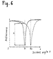
- Figure 6 is a graph showing the relationship between the reflectance of incident light and the incident angle thereof in the recording and reproducing medium according to the present invention.
- Figure 7 shows the principle of recording in an example of the recording and reproducing medium according to the present invention.
- Figure 8 shows the principle of recording in another example of the recording and reproducing medium according to the present invention.
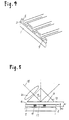
- Figure 9 shows the principle of a recording and reproducing apparatus which records and reproduces data in the conventional recording and reproducing medium.
- Figure 10 is a graph showing the relationship between the reflectance of incident light and the incident angle thereof in the conventional recording and reproducing medium.
- Figure 1 shows a recording and reproducing medium 7 in a card shape according to the present invention.
- the reference numerals 1, 3, and 5 denote a substrate, a heating layer, and a recording and reproducing layer, respectively.
- the heating layer 3 (thickness: 100 nm) made of a metal film such as Au is provided.
- the recording and reproducing layer 5 (thickness: 40 nm) is provided.
- the recording and reproducing layer 5 can be made of a phase-transition type material whose refractive index is different depending on states such as a crystalline state and an amorphous state.
- the recording and reproducing layer 5 can be made of a material having a magneto-optic effect.
- Figure 1 shows the recording and reproducing medium 7 on one side of which recording and reproducing are performed.
- the recording and reproducing medium 7 can be made so that recording and reproducing are performed on both sides thereof.
- the recording and reproducing medium 7 can be in a disk shape instead of a card shape.
- Figure 2A shows an example of the recording and reproducing medium 7 of the present invention.
- the heating layers (thickness: 100 nm) 3 are provided so as to fill grooves (depth: 400 nm, width: 500 nm) 9 formed on the substrate 1 .
- the recording and reproducing layer (thickness: 40 nm) 5 is provided so as to cover the substrate I and the heating layers 3 . It is desired that the depth of the grooves 9 is equal to or less than a wavelength (typically 100 to 400 nm) of incident light used for recording and reproducing data.
- Figure 2B shows another example of the recording and reproducing medium 7 of the present invention.
- a plurality of recessed portions 10 are formed in a matrix on the substrate 1 .
- the size of each recessed portion 10 is 500 nm x 500 nm. Because of this structure, the recording position of each data can be restricted to each recessed portion 10 . Thus, it becomes easy to discriminate data when the data is recorded and reproduced; as a result, the data can be recorded and reproduced with good reliability.
- Figure 3A shows another example of the recording and reproducing medium 7 of the present invention.
- the grooves 9 are formed on the substrate 1 .
- the heating layer 3 is made of a metal layer and formed by a sputtering method, etc. It is desired that the thickness of the heating layer 3 is set so that second groove 11 is formed in each of the grooves 9 .
- the recording and reproducing layer 5 is formed on the heating layer 3 .
- the upper surface of the heating layer 3 has first surface regions 14 (concave regions) and second surface regions 16 (convex regions). The data can be selectively recorded on the first surface regions 14 or on the second surface regions 16 .
- FIG. 3B shows another example of the recording and reproducing medium 7 of the present invention.
- each first surface region 14 has mounted portions 12 as preformat pits.
- the level of the mounted portion 12 is higher than the first surface region 14 and lower than the second surface region 16 .
- erasable data is repeatedly recorded and reproduced on the first surface regions 14 or on the second surface regions 16 , based on the change in characteristics of the recording and reproducing layer 5 .
- the erasure of data such as track number, signal position detecting data, etc. will damage the operation of the apparatus.
- such data is pre-recorded by arranging the position of the mounted portions 12 .
- the data based on the mounted portions 12 will not be erased, improving the reliability of the operation of the apparatus.
- each mounted portion 12 is provided on each first surface region 14 .
- a concave portion can be provided on each second surface region 16 instead of forming the mounted portion 12 on each first surface region 14 .
- each mounted portion 12 can be provided in a zigzag manner, instead of in a straight manner as shown in Figure 3B .
- Figure 4 shows another example of the recording and reproducing medium 7 of the present invention.
- the substrate 1 is flat and the heating layer 3 is formed thereon.
- the grooves 9 are formed in the heating layer 3 by a semiconductor fabrication technique (e.g., lithography and etching technique), and the recording and reproducing layer 5 is formed thereon.
- a semiconductor fabrication technique e.g., lithography and etching technique
- Figure 5 shows the principle of a recording and reproducing apparatus which records and reproduces data in the recording and reproducing mediums as shown in Figures 1 , 2A , 2B , 3A , 3B , and 4 .
- the medium 4 and the recording and reproducing layer 5 are filled between the prism 13 and the heating layer 3 .
- the medium 4 has a refractive index ns smaller than a refractive index np of the prism 13 , and the total thickness of the medium 4 and the recording and reproducing layer 5 is d1.
- the recording and reproducing layer 5 is made of a phase-transition type material having a thickness of d2 (smaller than d1 ) and a refractive index nt.
- the medium 4 and the recording and reproducing layer 5 should satisfy np > ns and nt > ns, respectively.
- the medium 4 is generally air (in this case, ns is about 1).
- ns is about 1
- As an incident light 15 a P-polarized light having a wavelength of ⁇ is incident upon the prism 13 at an angle ⁇ larger than a critical angle ⁇ c .
- the reference numeral 20 denotes a lens for condensing the incident light 15 at a bottom face 18 of the prism 13 .
- Figure 6 is a graph showing the relationship between the reflectance of the incident light 15 and the incident angle ⁇ thereof, where ⁇ is a variable. In general, it is desired that the thickness d1 is smaller than the wavelength ⁇ of the incident light 15 .
- the refractive index nt of the recording and reproducing layer 5 made of a phase-transition type material is locally different depending on portions thereof. That is to say, the refractive index nt in a portion 19 where data is to be recorded is different from that in a portion 17 where data is not to be recorded.
- the change of the reflectance of the incident light 15 with respect to the incident angle ⁇ in the portion 17 is represented by a solid line and the change of the reflectance in the portion 19 is represented by a broken line.
- the angle of the incident light 15 at which the surface plasmon resonance phenomenon is caused is ⁇ 1 .
- the angle of the incident light 15 at which the surface plasmon resonance phenomenon is caused is ⁇ 2 .
- the reflectance of the incident light 15 with respect to the incident angle ⁇ in the portion 19 is different from that in the portion 17 .
- the surface plasmon resonance phenomenon is also used.
- the reflectance of the incident light 15 becomes close to O. Because of this, as shown in Figure 7 , the optical wave is coupled with the vibration of plasma generated on the surface of the heating layer 3 , and part of the optical wave is converted into heat in the heating layer 3 .
- the recording and reproducing layer 5 is heated by the heat generated in the heating layer 3 , whereby thermal recording is performed.
- the recoding of data is performed by setting the incident angle ⁇ 1 so that the surface plasmon resonance phenomenon is caused at the portion 17 and by setting the amount of the incident light 15 so that the temperature of the recording and reproducing layer 5 is sufficiently raised by the heat generated in the heating layer 3 .
- the data recorded in the recording and reproducing layer 5 is erased by another optical system having the structure similar to that described above. If the incident angle of the incident light 15 is ⁇ 2, If the incident angle of the incident light 15 is ⁇ 2, the data can be erased in the same process as that during the recording.
- a higher recoding density can be obtained as follows: As shown in Figures 3A , 3B , and 4 , unevenness is provided on the surface of the heating layer 3 , the surface plasmon resonance phenomenon is caused only at concave regions or only at convex regions of the heating layer 3 . Alternatively, as shown in Figures 2A and 2B , the surface plasmon resonance phenomenon is selectively caused at portions where the heating layers 3 are filled. The surface plasmon resonance phenomenon is sensitive to the incident angle ⁇ of the incident light 15 and to the thickness d1 .
- a width T of each concave region or each convex region is set to be equal to or less than a beam spot diameter ⁇ D , only the convex regions or only the concave regions are selectively heated. Therefore, data which is smaller than the beam spot diameter can be recorded and reproduced.
- the recording and reproducing layer 5 is made of a magneto-optic material
- the principle of the recording is the same. That is, the heating layer 3 is heated due to the surface plasmon resonance phenomenon, whereby thermal recording is performed in the recording and reproducing layer 5 .
- the recording and reproducing layer 5 is made of a magneto-optic material
- the magnetic field in an adequate direction is applied, in response to the contents of data, to the recording and reproducing layer 5 , whereby data is recorded.
- the refractive index of the recording and reproducing layer 5 is hardly changed by recording data.
- the reproduced signal can be obtained by detecting the change of an S-polarized component and a P-polarized component of the reflected light. This detection can be performed by a detection optical system of a conventional magneto-optic recording apparatus.
- the recorded data can be erased by the same optical system as that used for recording.
- a bias magnetic circuit for inverting the direction of the magnetization of recorded data is required.
- the thickness of the heating layer 3 can be several ⁇ m, as long as the thickness is sufficiently larger than the depth of penetration of incident light for recording and reproducing data.
- the heating layer 3 can be made of a metal material which efficiently causes a surface plasmon resonance phenomenon and which is thermally stable. Examples of the metal material include Au, Pt, etc.
- the thickness of the recording and reproducing layer 5 is desirably 1000 ⁇ or less.
- the thickness d1 shown in Figure 5 is preferably equal to or less than a wavelength of the incident light 15 . It is more preferred that the thickness d1 is as small as possible. For example, assuming that the incident light 15 is an He-Ne laser beam, the wavelength thereof is about 0.63 ⁇ m. In this case, it is preferred that the thickness d1 is 0.1 ⁇ m or less.
- the present invention because of the surface plasmon resonance phenomenon, light energy can be efficiently converted into heat energy.
- the efficiency can be set at 90% or more under ideal conditions. This shows that according to the present invention, an efficiency twice that of the conventional system can be obtained.
- the local surface plasmon resonance phenomenon can be selectively caused. Thus, data is recorded and reproduced at a wavelength or less of the incident light.
Landscapes
- Chemical & Material Sciences (AREA)
- Inorganic Chemistry (AREA)
- Optical Recording Or Reproduction (AREA)
- Optical Record Carriers And Manufacture Thereof (AREA)
Description
- The present invention relates to a recording and reproducing medium which can be used with an apparatus for recording and reproducing data in the medium by using a laser beam.
- In general, optical disks (e.g., a compact disk) have been widely used for reproducing data in music or moving picture fields, because of the large capacity and low price thereof. The optical disks have also been used for peripheral equipment such as a computer, etc. In this field, it is required that the optical disks record and reproduce data. The optical disks generally use a thermal recording method. In this method, a laser beam for recording and reproducing data, emitted from a light source such as a laser device is condensed at a minute spot of a recording and reproducing medium. The optical characteristics of the minute spot region of the recording and reproducing medium are changed when being heated, whereby data is recorded therein. In such a thermal recording method, since the efficiency at which the energy of the laser beam is converted into heat is not high, high-speed recording and reproducing are difficult to perform, requiring the light source for a laser beam with a high output.
- In recent years, in order to overcome the above-mentioned problem, a reproducing method using a surface plasmon resonance phenomenon is proposed in Japanese Laid-Open Patent Publication No. 4-14620. In this method, a recording layer can be made thin, so that data is recorded using a light source for a laser beam with a relatively low output.
- Hereinafter, a conventional example of a recording and reproducing system aiming at high-speed recording will be described with reference to Figure 9.
- A
medium 4 is filled between aprism 103 and ametal layer 101. Themedium 4 has a refractive index ns which is smaller than the refractive index np of theprism 103 and has a thickness of d1. In general, themedium 4 should satisfy np > ns. Themedium 4 is usually air (in this case, ns is about 1). As anincident light 106, a P-polarized light having a wavelength of λ is incident upon theprism 103 at an incident angle larger than a critical angle c. When theincident light 106 is incident upon theprism 103 at a particular angle 1, an evanescent wave generated under an interface (i.e., the bottom face of the prism 103) is resonated with the vibration of plasma present between themedium 4 and themetal layer 101, thereby causing the surface plasmon resonance phenomenon. Because of this, the reflectance of theincident light 106 is reduced. In general, it is desired that the thickness d1 is smaller than a wavelength λ of theincident light 106. - Figure 10 is a graph showing the relationship between the reflectance of the
incident light 106 and the incident angle thereof, where is a variable. A solid line shows the change in reflectance of theincident light 106 with respect to the incident angle . As is understood from Figure 10, the angle of theincident light 106 at which the surface plasmon resonance phenomenon is caused is 1. When a dielectricthin film 102 having a thickness of d2 smaller than d1 is formed on themetal layer 101, the angle of theincident light 106 at which the surface plasmon resonance phenomenon is caused is 2, and in this case, the characteristic curve of the reflectance is represented by a broken line in Figure 10. In this way, the characteristic curve of the reflectance with respect to the incident angle in a portion where the dielectricthin film 102 is formed is different from that in a portion where the dielectricthin film 102 is not formed. If the surface of a recording and reproducing medium is scanned under the condition that the incident angle is fixed at 1, the amount of reflected light in a portion where the dielectricthin film 102 is formed is different from that in a portion where the dielectricthin film 102 is not formed, whereby a reproduced signal A can be obtained. - On the other hand, during the recording, a laser beam is directly irradiated to the dielectric
thin film 102 and the dielectricthin film 102 is melted or sublimed with the heat generated at a beam spot to form a pit therein. The dielectricthin film 102 can be formed of an organic monomolecular film or a layered structure including a plurality of films. - However, in the above-mentioned structure, recording data is performed by melting or subliming selected portions of the dielectric
thin film 102, so that recording new data cannot be repeatedly performed. In addition, separate light sources are required, respectively for recording and reproducing. Moreover, it is difficult to improve the recording density, because the recording density is determined by the spot size of a laser beam. - The recording and reproducing medium of the present invention, includes:
- at least one recording and reproducing layer; and
- a heating layer being made of a metal material which receives light for writing data, to convert a part of energy of the light into heat by a surface plasmon resonance phenomenon and to heat a portion of the recording and reproducing layer, thereby changing optical characteristics of the desired portion,
- wherein the heating layer is separated into a plurality of portions.
-
- In one embodiment of the present invention, the recording and reproducing layer is made of a phase-transition type material.
- In another embodiment of the present invention, the recording and reproducing layer is made of a magneto-optic material.
- In still another embodiment of the present invention, the heating layer is made of Au or Pt.
- In still another embodiment of the present invention, the above-mentioned medium further includes a substrate supporting the recording and reproducing layer and the heating layer.
- In still another embodiment of the present invention, each of the plurality of separated portions of the heating layer is in a stripe shape.
- In still another embodiment of the present invention, the substrate having a surface on which a plurality of grooves are formed,
wherein the plurality of portions of the heating layer are provided in the plurality of grooves. - In still another embodiment of the present invention, each width of the plurality of stripe-shaped portions is smaller than a spot diameter of the light.
- In still another embodiment of the present invention, a distance between the respective plurality of stripe-shaped portions is smaller than the spot diameter of the light.
- In still another embodiment of the present invention, the plurality of stripe-shaped portions are arranged at a predetermined pitch in a regular manner, and the pitch is smaller than the spot diameter of the light.
- In still another embodiment of the present invention, the plurality of portions are arranged in a matrix.
- Thus, the invention described herein makes possible the advantages of providing a recording and reproducing medium capable of repeatedly recording and reproducing data, and recording and reproducing data smaller than the spot size of a laser beam.
- This and other advantages of the present invention will become apparent to those skilled in the art upon reading and understanding the following detailed description with reference to the accompanying figures.
- Figure 1 shows a recording and reproducing medium according to the present invention.
- Figure 2A shows an example of the recording and reproducing medium according to the present invention.
- Figure 2B shows another example of the recording and reproducing medium according to the present invention.
- Figure 3A shows still another example of the recording and reproducing medium according to the present invention.
- Figure 3B shows still another example of the recording and reproducing medium according to the present invention.
- Figure 4 shows still another example of the recording and reproducing medium according to the present invention.
- Figure 5 schematically shows a recording and reproducing apparatus which records and reproduces data in the medium according to the present invention.
- Figure 6 is a graph showing the relationship between the reflectance of incident light and the incident angle thereof in the recording and reproducing medium according to the present invention.
- Figure 7 shows the principle of recording in an example of the recording and reproducing medium according to the present invention.
- Figure 8 shows the principle of recording in another example of the recording and reproducing medium according to the present invention.
- Figure 9 shows the principle of a recording and reproducing apparatus which records and reproduces data in the conventional recording and reproducing medium.
- Figure 10 is a graph showing the relationship between the reflectance of incident light and the incident angle thereof in the conventional recording and reproducing medium.
- Hereinafter, the present invention will be described by way of illustrative examples with reference to the drawings.
- Figure 1 shows a recording and reproducing medium 7 in a card shape according to the present invention. The
reference numerals substrate 1, the heating layer 3 (thickness: 100 nm) made of a metal film such as Au is provided. On theheating layer 3, the recording and reproducing layer 5 (thickness: 40 nm) is provided. The recording and reproducinglayer 5 can be made of a phase-transition type material whose refractive index is different depending on states such as a crystalline state and an amorphous state. Alternatively, the recording and reproducinglayer 5 can be made of a material having a magneto-optic effect. - Figure 1 shows the recording and reproducing medium 7 on one side of which recording and reproducing are performed. However, the recording and reproducing medium 7 can be made so that recording and reproducing are performed on both sides thereof. In addition, the recording and reproducing medium 7 can be in a disk shape instead of a card shape.
- Figure 2A shows an example of the recording and reproducing
medium 7 of the present invention. The heating layers (thickness: 100 nm) 3 are provided so as to fill grooves (depth: 400 nm, width: 500 nm) 9 formed on thesubstrate 1. The recording and reproducing layer (thickness: 40 nm) 5 is provided so as to cover the substrate I and the heating layers 3. It is desired that the depth of thegrooves 9 is equal to or less than a wavelength (typically 100 to 400 nm) of incident light used for recording and reproducing data. - Figure 2B shows another example of the recording and reproducing
medium 7 of the present invention. In this example, a plurality of recessedportions 10 are formed in a matrix on thesubstrate 1. For example, the size of each recessedportion 10 is 500 nm x 500 nm. Because of this structure, the recording position of each data can be restricted to each recessedportion 10. Thus, it becomes easy to discriminate data when the data is recorded and reproduced; as a result, the data can be recorded and reproduced with good reliability. - Figure 3A shows another example of the recording and reproducing
medium 7 of the present invention. In the same way as in Figure 2A, thegrooves 9 are formed on thesubstrate 1. Theheating layer 3 is made of a metal layer and formed by a sputtering method, etc. It is desired that the thickness of theheating layer 3 is set so that second groove 11 is formed in each of thegrooves 9. - In this example, after the
continuous heating layer 3 is formed over thegrooved substrate 1, the recording and reproducinglayer 5 is formed on theheating layer 3. The upper surface of theheating layer 3 has first surface regions 14 (concave regions) and second surface regions 16 (convex regions). The data can be selectively recorded on thefirst surface regions 14 or on thesecond surface regions 16. - Figure 3B shows another example of the recording and reproducing
medium 7 of the present invention. In this example, eachfirst surface region 14 has mountedportions 12 as preformat pits. The level of the mountedportion 12 is higher than thefirst surface region 14 and lower than thesecond surface region 16. In this example, erasable data is repeatedly recorded and reproduced on thefirst surface regions 14 or on thesecond surface regions 16, based on the change in characteristics of the recording and reproducinglayer 5. The erasure of data such as track number, signal position detecting data, etc. will damage the operation of the apparatus. In this example, such data is pre-recorded by arranging the position of the mountedportions 12. The data based on the mountedportions 12 will not be erased, improving the reliability of the operation of the apparatus. In Figure 3B, each mountedportion 12 is provided on eachfirst surface region 14. Alternatively, a concave portion can be provided on eachsecond surface region 16 instead of forming the mountedportion 12 on eachfirst surface region 14. In addition, each mountedportion 12 can be provided in a zigzag manner, instead of in a straight manner as shown in Figure 3B. - Figure 4 shows another example of the recording and reproducing
medium 7 of the present invention. Thesubstrate 1 is flat and theheating layer 3 is formed thereon. Thegrooves 9 are formed in theheating layer 3 by a semiconductor fabrication technique (e.g., lithography and etching technique), and the recording and reproducinglayer 5 is formed thereon. - Figure 5 shows the principle of a recording and reproducing apparatus which records and reproduces data in the recording and reproducing mediums as shown in Figures 1, 2A, 2B, 3A, 3B, and 4.
- The
medium 4 and the recording and reproducinglayer 5 are filled between theprism 13 and theheating layer 3. Themedium 4 has a refractive index ns smaller than a refractive index np of theprism 13, and the total thickness of themedium 4 and the recording and reproducinglayer 5 is d1. Here, the recording and reproducinglayer 5 is made of a phase-transition type material having a thickness of d2 (smaller than d1) and a refractive index nt. - In general, the
medium 4 and the recording and reproducinglayer 5 should satisfy np > ns and nt > ns, respectively. Themedium 4 is generally air (in this case, ns is about 1). As anincident light 15, a P-polarized light having a wavelength of λ is incident upon theprism 13 at an angle larger than a critical angle c. Thereference numeral 20 denotes a lens for condensing the incident light 15 at a bottom face 18 of theprism 13. When theincident light 15 having a particular incident angle 1 is incident upon theprism 13, an evanescent wave generated under the interface (i.e., the bottom face 18) is resonated with the vibration of plasma present between the recording and reproducinglayer 5 and theheating layer 3 to cause a surface plasmon resonance phenomenon. Because of this, the reflectance of theincident light 15 is reduced. In the case where ns, np, and nt are determined, main parameters for causing the surface plasmon resonance phenomenon at the highest efficiency are the angle of theincident light 15, the wavelength λ thereof, and the thickness d1. - Figure 6 is a graph showing the relationship between the reflectance of the
incident light 15 and the incident angle thereof, where is a variable. In general, it is desired that the thickness d1 is smaller than the wavelength λ of theincident light 15. The refractive index nt of the recording and reproducinglayer 5 made of a phase-transition type material is locally different depending on portions thereof. That is to say, the refractive index nt in aportion 19 where data is to be recorded is different from that in aportion 17 where data is not to be recorded. In Figure 6, the change of the reflectance of the incident light 15 with respect to the incident angle in theportion 17 is represented by a solid line and the change of the reflectance in theportion 19 is represented by a broken line. As is understood from Figure 6, in theportion 17, the angle of the incident light 15 at which the surface plasmon resonance phenomenon is caused is 1. In theportion 19, the angle of the incident light 15 at which the surface plasmon resonance phenomenon is caused is 2. In this way, the reflectance of the incident light 15 with respect to the incident angle in theportion 19 is different from that in theportion 17. When the surface of the recording and reproducing medium is scanned under the condition that the incident angle is set at 1, the amount of reflected light to varied depending upon the portions of the recording and reproducinglayer 5, whereby a reproduced signal A can be detected. - In the case where data is recorded in the above-mentioned recording and reproducing medium, the surface plasmon resonance phenomenon is also used. When the surface plasmon resonance phenomenon is caused, the reflectance of the
incident light 15 becomes close to O. Because of this, as shown in Figure 7, the optical wave is coupled with the vibration of plasma generated on the surface of theheating layer 3, and part of the optical wave is converted into heat in theheating layer 3. The recording and reproducinglayer 5 is heated by the heat generated in theheating layer 3, whereby thermal recording is performed. - Thus, the recoding of data is performed by setting the incident angle 1 so that the surface plasmon resonance phenomenon is caused at the
portion 17 and by setting the amount of the incident light 15 so that the temperature of the recording and reproducinglayer 5 is sufficiently raised by the heat generated in theheating layer 3. - The data recorded in the recording and reproducing
layer 5 is erased by another optical system having the structure similar to that described above. If the incident angle of theincident light 15 is 2, If the incident angle of theincident light 15 is 2, the data can be erased in the same process as that during the recording. - In addition, a higher recoding density can be obtained as follows: As shown in Figures 3A, 3B, and 4, unevenness is provided on the surface of the
heating layer 3, the surface plasmon resonance phenomenon is caused only at concave regions or only at convex regions of theheating layer 3. Alternatively, as shown in Figures 2A and 2B, the surface plasmon resonance phenomenon is selectively caused at portions where the heating layers 3 are filled. The surface plasmon resonance phenomenon is sensitive to the incident angle of theincident light 15 and to the thickness d1. Thus, as shown in Figure 8, in the case where the convex regions are formed so that the thickness between the bottom surface of theprism 13 and each top surface of the convex regions is d1, the surface plasmon resonance phenomenon is generated only at the convex regions to heat theheating layer 3, but heat is not generated in the concave regions. On the other hand, in the case where the concave regions are formed so that the thickness between the bottom surface of theprism 13 and each bottom surface of the concave regions is d1, the surface plasmon resonance phenomenon is generated only at the concave regions to heat theheating layer 3, but heat is not generated in the convex regions. - Due to the above-mentioned characteristics, the following is possible:
- For example, when a width T of each concave region or each convex region is set to be equal to or less than a beam spot diameter D, only the convex regions or only the concave regions are selectively heated. Therefore, data which is smaller than the beam spot diameter can be recorded and reproduced.
- In the case where the recording and reproducing
layer 5 is made of a magneto-optic material, the principle of the recording is the same. That is, theheating layer 3 is heated due to the surface plasmon resonance phenomenon, whereby thermal recording is performed in the recording and reproducinglayer 5. In the case where the recording and reproducinglayer 5 is made of a magneto-optic material, when the temperature of the recording and reproducinglayer 5 exceeds a Curie temperature, the magnetic field in an adequate direction is applied, in response to the contents of data, to the recording and reproducinglayer 5, whereby data is recorded. In this case, the refractive index of the recording and reproducinglayer 5 is hardly changed by recording data. Thus, the amount of change in the intensity of the reproducing light as reflected is remarkably decreased. However, the reproduced signal can be obtained by detecting the change of an S-polarized component and a P-polarized component of the reflected light. This detection can be performed by a detection optical system of a conventional magneto-optic recording apparatus. - In this recording and reproducing medium, the recorded data can be erased by the same optical system as that used for recording. However, a bias magnetic circuit for inverting the direction of the magnetization of recorded data is required.
- In the examples of the present invention, the thickness of the
heating layer 3 can be several µm, as long as the thickness is sufficiently larger than the depth of penetration of incident light for recording and reproducing data. Theheating layer 3 can be made of a metal material which efficiently causes a surface plasmon resonance phenomenon and which is thermally stable. Examples of the metal material include Au, Pt, etc. The thickness of the recording and reproducinglayer 5 is desirably 1000 Å or less. In addition, the thickness d1 shown in Figure 5 is preferably equal to or less than a wavelength of theincident light 15. It is more preferred that the thickness d1 is as small as possible. For example, assuming that theincident light 15 is an He-Ne laser beam, the wavelength thereof is about 0.63 µm. In this case, it is preferred that the thickness d1 is 0.1 µm or less. - As described above, according to the present invention, because of the surface plasmon resonance phenomenon, light energy can be efficiently converted into heat energy. The efficiency can be set at 90% or more under ideal conditions. This shows that according to the present invention, an efficiency twice that of the conventional system can be obtained. Moreover, because of the unevenness of the surface of the recording and reproducing medium and the pattern formation on the heating layer, the local surface plasmon resonance phenomenon can be selectively caused. Thus, data is recorded and reproduced at a wavelength or less of the incident light.
- Various other modifications will be apparent to and can be readily made by those skilled in the art without departing from the scope of this invention as defined in the claims appended hereto.
Claims (11)
- A recording and reproducing medium (7) comprising:characterized in thata) at least one recording and reproducing layer (5); andb) a heating layer (3) being made of a metal material which receives light for writing data to convert a part of energy of the light into heat by a surface plasmon resonance phenomenon, and to heat a portion of the recording and reproducing layer (5), thereby changing optical characteristics of the desired portion;c) the heating layer (3) is separated into a plurality of portions.
- A recording and reproducing medium according to claim 1, wherein the recording and reproducing layer (5) is made of a phase-transition type material.
- A recording and reproducing medium according to claim 1, wherein the recording and reproducing layer (5) is made of a magneto-optic material.
- A recording and reproducing medium according to one of claims 1 to 3, wherein the heating layer (3) is made of Au or Pt.
- . A recording and reproducing medium according to one of the preceding claims, further comprising a substrate (1) supporting the recording and reproducing layer (5) and the heating layer (3).
- A recording and reproducing medium according to one of the preceding claims, wherein each of the plurality of separated portions of the heating layer (3) is in a stripe shape.
- A recording and reproducing medium according to claims 5 and 6, the substrate (1) having a surface on which a plurality of grooves (9) are formed,wherein the plurality of portions of the heating layer (3) are provided in the plurality of grooves (9).
- A recording and reproducing medium according to claims 6 or 7, wherein each width of the plurality of stripe-shaped portions is smaller than a spot diameter of the light.
- A recording and reproducing medium according to one of claims 6 to 8, wherein a distance between the respective plurality of stripe-shaped portions is smaller than the spot diameter of the light.
- A recording and reproducing medium according to one of claims 6 to 9. wherein the plurality of stripe-shaped portions are arranged at a predetermined pitch in a regular manner, and the pitch is smaller than the spot diameter of the light.
- A recording and reproducing medium according to one of the preceding claims, wherein the plurality of portions are arranged in a matrix.
Applications Claiming Priority (3)
| Application Number | Priority Date | Filing Date | Title |
|---|---|---|---|
| JP28575792 | 1992-10-23 | ||
| JP285757/92 | 1992-10-23 | ||
| JP4285757A JPH06139620A (en) | 1992-10-23 | 1992-10-23 | Recording / reproducing medium and recording / reproducing apparatus |
Publications (3)
| Publication Number | Publication Date |
|---|---|
| EP0594194A2 EP0594194A2 (en) | 1994-04-27 |
| EP0594194A3 EP0594194A3 (en) | 1995-07-05 |
| EP0594194B1 true EP0594194B1 (en) | 1999-12-22 |
Family
ID=17695660
Family Applications (1)
| Application Number | Title | Priority Date | Filing Date |
|---|---|---|---|
| EP93117153A Expired - Lifetime EP0594194B1 (en) | 1992-10-23 | 1993-10-22 | A recording and reproducing medium and a recording and reproducing apparatus |
Country Status (5)
| Country | Link |
|---|---|
| US (2) | US5582896A (en) |
| EP (1) | EP0594194B1 (en) |
| JP (1) | JPH06139620A (en) |
| KR (1) | KR940009986A (en) |
| DE (1) | DE69327382T2 (en) |
Families Citing this family (17)
| Publication number | Priority date | Publication date | Assignee | Title |
|---|---|---|---|---|
| JPH05334664A (en) * | 1992-06-02 | 1993-12-17 | Pioneer Electron Corp | Information recording disk and its recorded information reproducing device |
| US5910940A (en) * | 1996-10-08 | 1999-06-08 | Polaroid Corporation | Storage medium having a layer of micro-optical lenses each lens generating an evanescent field |
| JP4073525B2 (en) * | 1997-09-05 | 2008-04-09 | 株式会社ルネサステクノロジ | Nonvolatile semiconductor memory device |
| EP1047464B8 (en) | 1997-12-19 | 2007-11-21 | United States Surgical Corporation | Two component dispenser system |
| JP4313517B2 (en) * | 2000-01-26 | 2009-08-12 | セイコーインスツル株式会社 | Recording medium, near-field optical head, optical recording apparatus, and manufacturing method thereof |
| US6784095B1 (en) | 2001-02-14 | 2004-08-31 | Advanced Micro Devices, Inc. | Phosphine treatment of low dielectric constant materials in semiconductor device manufacturing |
| US6566283B1 (en) | 2001-02-15 | 2003-05-20 | Advanced Micro Devices, Inc. | Silane treatment of low dielectric constant materials in semiconductor device manufacturing |
| JP2002319119A (en) * | 2001-04-23 | 2002-10-31 | Fuji Electric Co Ltd | Substrate for perpendicular magnetic recording medium, perpendicular magnetic recording medium using the substrate, and method of manufacturing them |
| US8345374B2 (en) | 2003-05-29 | 2013-01-01 | Seagate Technology, Llc | Patterned media for heat assisted magnetic recording |
| AU2003234686A1 (en) * | 2003-05-29 | 2005-01-21 | Seagate Technology Llc | Patterned media for heat assisted magnetic recording |
| ES2261009B1 (en) * | 2004-06-11 | 2007-11-16 | Consejo Superior De Investigaciones Cientificas. | DEVICE AND METHOD FOR DETECTING CHANGES IN THE REFRACTION INDEX OF A DIELECTRIC ENVIRONMENT. |
| JP2008507806A (en) | 2004-07-26 | 2008-03-13 | インペリアル・イノベイションズ・リミテッド | Optical disc and reading device therefor |
| US8031561B2 (en) * | 2009-10-28 | 2011-10-04 | Hitachi Global Storage Technologies Netherlands B.V. | Joint design of thermally-assisted magnetic recording head and patterned media for high optical efficiency |
| US9372241B2 (en) * | 2009-11-06 | 2016-06-21 | Headway Technologies, Inc. | Multi-directional pin anneal of MR sensors with plasmon heating |
| JP5793717B2 (en) * | 2010-08-23 | 2015-10-14 | パナソニックIpマネジメント株式会社 | Optical information reproducing apparatus, optical information reproducing method, and information recording medium |
| KR101596712B1 (en) * | 2015-01-14 | 2016-02-23 | 현대자동차주식회사 | Eco-humidifier for vehicle |
| DE102021202924A1 (en) | 2021-03-25 | 2022-09-29 | Robert Bosch Gesellschaft mit beschränkter Haftung | Method for locally modifying a layer property, method for manufacturing a magnetoresistive sensor device and magnetoresistive sensor device |
Family Cites Families (12)
| Publication number | Priority date | Publication date | Assignee | Title |
|---|---|---|---|---|
| US3815969A (en) * | 1973-05-31 | 1974-06-11 | Nasa | Holography utilizing surface plasmon resonances |
| US4616237A (en) * | 1982-09-27 | 1986-10-07 | Pa Management Consultants, Ltd. | Data storage medium |
| JPS60500148A (en) * | 1982-12-06 | 1985-01-31 | コムテツク リサ−チ ユニツト リミテツド | Image formation and data storage |
| WO1984004420A1 (en) * | 1983-04-28 | 1984-11-08 | Comtech Res Unit | Data storage and recording |
| US5014254A (en) * | 1988-05-09 | 1991-05-07 | U.S. Philips Corporation | Magneto-optical recording method and magneto-optical recording apparatus |
| DE3906521A1 (en) * | 1989-03-02 | 1990-09-13 | Basf Ag | METHOD FOR READING INFORMATION STORED IN THICK POLYMER LAYERS |
| JPH02308423A (en) * | 1989-05-22 | 1990-12-21 | Toshiba Corp | Reproducing method for optical recording medium |
| WO1991006035A1 (en) * | 1989-10-18 | 1991-05-02 | Research Corporation Technologies, Inc. | Light-sensitive recording media |
| JPH0414620A (en) * | 1990-05-09 | 1992-01-20 | Canon Inc | Optical recording and reproducing method |
| JPH0462090A (en) * | 1990-06-25 | 1992-02-27 | Ube Ind Ltd | Optical recording medium and its writing for recording and reading |
| JP3135389B2 (en) * | 1992-10-23 | 2001-02-13 | 松下電器産業株式会社 | Information reproducing method, information recording / reproducing method, information reproducing apparatus, recording medium, and optical head |
| FR2781770B1 (en) * | 1998-07-30 | 2000-10-13 | Valois Sa | FLUID PRODUCT SAMPLE |
-
1992
- 1992-10-23 JP JP4285757A patent/JPH06139620A/en active Pending
-
1993
- 1993-10-19 KR KR1019930021662A patent/KR940009986A/en not_active Ceased
- 1993-10-21 US US08/141,130 patent/US5582896A/en not_active Expired - Lifetime
- 1993-10-22 EP EP93117153A patent/EP0594194B1/en not_active Expired - Lifetime
- 1993-10-22 DE DE69327382T patent/DE69327382T2/en not_active Expired - Fee Related
-
1996
- 1996-03-21 US US08/619,988 patent/US5614279A/en not_active Expired - Lifetime
Also Published As
| Publication number | Publication date |
|---|---|
| JPH06139620A (en) | 1994-05-20 |
| EP0594194A2 (en) | 1994-04-27 |
| KR940009986A (en) | 1994-05-24 |
| EP0594194A3 (en) | 1995-07-05 |
| US5582896A (en) | 1996-12-10 |
| US5614279A (en) | 1997-03-25 |
| DE69327382D1 (en) | 2000-01-27 |
| DE69327382T2 (en) | 2000-05-11 |
Similar Documents
| Publication | Publication Date | Title |
|---|---|---|
| US5614279A (en) | Recording and reproducing medium and a recording and reproducing apparatus | |
| JP3057516B2 (en) | Method of reproducing signal from optical recording medium | |
| US6226258B1 (en) | Optical recording medium with transmissivity controlling layer | |
| US6049521A (en) | Optical recording medium and method for producing same | |
| US5432774A (en) | Optical recording medium | |
| EP0683485A1 (en) | Phase change type optical disk | |
| US6410115B1 (en) | Multi-rewritable optical recording medium with surface plasmon super-resolution layer | |
| US6741549B2 (en) | Optical recording medium and optical recording and reproduction apparatus | |
| US7572496B2 (en) | Recording medium having high melting point recording layer, information recording method thereof, and information reproducing apparatus and method therefor | |
| EP0829866B1 (en) | Optical information recording medium | |
| EP0564260A2 (en) | Optical recording medium and optical recording/reproducing apparatus | |
| EP1067533A2 (en) | Optical recording medium and optical recording and reproducing device | |
| US6348251B1 (en) | Inorganic write-once optical recording medium with surface plasmon super-resolution layer | |
| US7651793B2 (en) | High density recording medium with super-resolution near-field structure manufactured using high-melting point metal oxide or silicon oxide mask layer | |
| US7016290B2 (en) | Readout method and apparatus for optical information medium | |
| JP2723004B2 (en) | Optical recording medium and recording / reproducing method thereof | |
| US6967050B2 (en) | Optical recording medium and a method of manufacturing the same | |
| US6459659B1 (en) | Recording medium having planar aperture array and fabrication method thereof, and near-field optical recording/reproducing device using same and method therefor | |
| US6117511A (en) | Optical recording media | |
| JP2510320B2 (en) | Optical recording medium | |
| JP2807470B2 (en) | Optical memory device | |
| EP1324329B1 (en) | Magneto-optical recording method and apparatus | |
| JP2689856B2 (en) | Optical recording medium | |
| JP3139479B2 (en) | Information recording medium, method for manufacturing information recording medium, method for recording / reproducing information, and method for erasing information | |
| JP4381540B2 (en) | Reproduction method of optical recording medium |
Legal Events
| Date | Code | Title | Description |
|---|---|---|---|
| PUAI | Public reference made under article 153(3) epc to a published international application that has entered the european phase |
Free format text: ORIGINAL CODE: 0009012 |
|
| 17P | Request for examination filed |
Effective date: 19931022 |
|
| AK | Designated contracting states |
Kind code of ref document: A2 Designated state(s): DE FR GB NL |
|
| PUAL | Search report despatched |
Free format text: ORIGINAL CODE: 0009013 |
|
| AK | Designated contracting states |
Kind code of ref document: A3 Designated state(s): DE FR GB NL |
|
| 17Q | First examination report despatched |
Effective date: 19961217 |
|
| GRAG | Despatch of communication of intention to grant |
Free format text: ORIGINAL CODE: EPIDOS AGRA |
|
| GRAG | Despatch of communication of intention to grant |
Free format text: ORIGINAL CODE: EPIDOS AGRA |
|
| GRAH | Despatch of communication of intention to grant a patent |
Free format text: ORIGINAL CODE: EPIDOS IGRA |
|
| GRAH | Despatch of communication of intention to grant a patent |
Free format text: ORIGINAL CODE: EPIDOS IGRA |
|
| GRAA | (expected) grant |
Free format text: ORIGINAL CODE: 0009210 |
|
| AK | Designated contracting states |
Kind code of ref document: B1 Designated state(s): DE FR GB NL |
|
| REF | Corresponds to: |
Ref document number: 69327382 Country of ref document: DE Date of ref document: 20000127 |
|
| ET | Fr: translation filed | ||
| PLBE | No opposition filed within time limit |
Free format text: ORIGINAL CODE: 0009261 |
|
| STAA | Information on the status of an ep patent application or granted ep patent |
Free format text: STATUS: NO OPPOSITION FILED WITHIN TIME LIMIT |
|
| 26N | No opposition filed | ||
| REG | Reference to a national code |
Ref country code: GB Ref legal event code: IF02 |
|
| PGFP | Annual fee paid to national office [announced via postgrant information from national office to epo] |
Ref country code: NL Payment date: 20061015 Year of fee payment: 14 |
|
| PGFP | Annual fee paid to national office [announced via postgrant information from national office to epo] |
Ref country code: GB Payment date: 20061018 Year of fee payment: 14 |
|
| PGFP | Annual fee paid to national office [announced via postgrant information from national office to epo] |
Ref country code: DE Payment date: 20061019 Year of fee payment: 14 |
|
| GBPC | Gb: european patent ceased through non-payment of renewal fee |
Effective date: 20071022 |
|
| NLV4 | Nl: lapsed or anulled due to non-payment of the annual fee |
Effective date: 20080501 |
|
| PG25 | Lapsed in a contracting state [announced via postgrant information from national office to epo] |
Ref country code: DE Free format text: LAPSE BECAUSE OF NON-PAYMENT OF DUE FEES Effective date: 20080501 |
|
| REG | Reference to a national code |
Ref country code: FR Ref legal event code: ST Effective date: 20080630 |
|
| PG25 | Lapsed in a contracting state [announced via postgrant information from national office to epo] |
Ref country code: NL Free format text: LAPSE BECAUSE OF NON-PAYMENT OF DUE FEES Effective date: 20080501 |
|
| PGFP | Annual fee paid to national office [announced via postgrant information from national office to epo] |
Ref country code: FR Payment date: 20061010 Year of fee payment: 14 |
|
| PG25 | Lapsed in a contracting state [announced via postgrant information from national office to epo] |
Ref country code: GB Free format text: LAPSE BECAUSE OF NON-PAYMENT OF DUE FEES Effective date: 20071022 |
|
| PG25 | Lapsed in a contracting state [announced via postgrant information from national office to epo] |
Ref country code: FR Free format text: LAPSE BECAUSE OF NON-PAYMENT OF DUE FEES Effective date: 20071031 |