EP0593445B1 - Sealed pouch having tear-open spout - Google Patents
Sealed pouch having tear-open spout Download PDFInfo
- Publication number
- EP0593445B1 EP0593445B1 EP90917441A EP90917441A EP0593445B1 EP 0593445 B1 EP0593445 B1 EP 0593445B1 EP 90917441 A EP90917441 A EP 90917441A EP 90917441 A EP90917441 A EP 90917441A EP 0593445 B1 EP0593445 B1 EP 0593445B1
- Authority
- EP
- European Patent Office
- Prior art keywords
- pouch
- fluid
- spout
- defines
- sealed
- Prior art date
- Legal status (The legal status is an assumption and is not a legal conclusion. Google has not performed a legal analysis and makes no representation as to the accuracy of the status listed.)
- Expired - Lifetime
Links
Images

Classifications
-
- B—PERFORMING OPERATIONS; TRANSPORTING
- B65—CONVEYING; PACKING; STORING; HANDLING THIN OR FILAMENTARY MATERIAL
- B65D—CONTAINERS FOR STORAGE OR TRANSPORT OF ARTICLES OR MATERIALS, e.g. BAGS, BARRELS, BOTTLES, BOXES, CANS, CARTONS, CRATES, DRUMS, JARS, TANKS, HOPPERS, FORWARDING CONTAINERS; ACCESSORIES, CLOSURES, OR FITTINGS THEREFOR; PACKAGING ELEMENTS; PACKAGES
- B65D75/00—Packages comprising articles or materials partially or wholly enclosed in strips, sheets, blanks, tubes, or webs of flexible sheet material, e.g. in folded wrappers
- B65D75/52—Details
- B65D75/58—Opening or contents-removing devices added or incorporated during package manufacture
- B65D75/5816—Opening or contents-removing devices added or incorporated during package manufacture for tearing a corner or other small portion next to the edge, e.g. a U-shaped portion
- B65D75/5822—Opening or contents-removing devices added or incorporated during package manufacture for tearing a corner or other small portion next to the edge, e.g. a U-shaped portion and defining, after tearing, a small dispensing spout, a small orifice or the like
-
- B—PERFORMING OPERATIONS; TRANSPORTING
- B65—CONVEYING; PACKING; STORING; HANDLING THIN OR FILAMENTARY MATERIAL
- B65D—CONTAINERS FOR STORAGE OR TRANSPORT OF ARTICLES OR MATERIALS, e.g. BAGS, BARRELS, BOTTLES, BOXES, CANS, CARTONS, CRATES, DRUMS, JARS, TANKS, HOPPERS, FORWARDING CONTAINERS; ACCESSORIES, CLOSURES, OR FITTINGS THEREFOR; PACKAGING ELEMENTS; PACKAGES
- B65D75/00—Packages comprising articles or materials partially or wholly enclosed in strips, sheets, blanks, tubes, or webs of flexible sheet material, e.g. in folded wrappers
- B65D75/008—Standing pouches, i.e. "Standbeutel"
Definitions
- Our invention relates, in general, to sealed pouches made of molecularly-orientable polymeric film that is sealed along peripheral edge margins.
- Plastic film of, for example, polyethylene or polypropylene is virtually impossible to tear directly along a straight or other regular line. This is due to the fact that two forces, when applied in opposite directions in shear or tension over an area of such a film or thin sheet, can cause the plastic film material to deform and stretch plastically until its elastic limit is passed, whereupon a tear or separation starts. Such a tear can begin anywhere in the deformed, stretched area -- which is usually at the weakest point produced by the above-described thickness reduction -- and will not, in general, run normal to the tearing forces being applied. Thus, even with evenly and carefully applied forces, it is not likely that a person will be able to tear a plastic film along a preselected straight or other regular line due to the stretchability of the film.
- the sealed pouch is made of a molecularly-orientable polymeric film that is sealed along peripheral edge margins.
- the pouch defines a sealed cavity for containment of a fluid.
- the pouch also defines a sealed fluid-discharge spout that is in fluid communication with the fluid cavity.
- the pouch further defines a seam disposed between the fluid cavity and the spout.
- the improvement comprises at least three essential features.
- One such feature is that a portion of the polymeric film which defines a fluid-discharge end of the spout is molecularly-oriented in a preselected direction.
- Another such feature is that a portion of the seam defines a slit disposed transverse to the preselected direction.
- Still another feature is that a portion of the sealed pouch peripheral edge margin in the vicinity of the fluid-discharge end of the spout defines a tear-initiating notch oriented along the preselected direction.
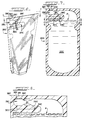
- Figure 1 is a perspective view of one embodiment of our present invention.
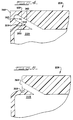
- Figure 2 is a sectional view, taken along the plane 2-2 in Figure 1, and slightly enlarged relative to Figure 1.
- Figure 3 is a fragmented sectional view, taken along the lines 3-3 in Figure 2 and on an enlarged scale.
- Figure 4 is a fragmented sectional view of another embodiment of our present invention, illustrating the tear-open spout.
- Figure 5 is a fragmented sectional view, similar to Figure 4, but illustrating the now torn-open spout.
- Figure 6 is a perspective view of still another embodiment of our present invention.
- Figure 7 is a sectional view, taken along the plane 7-7 in Figure 6, and slightly enlarged relative to Figure 6.
- Figure 8 is a fragmented sectional view, generally taken along the line 8-8 in Figure 7 and on an enlarged scale.
- edge margins of flexible plastic pouches can be joined continuously utilizing such sealing methods as heat-and-pressure, radio-frequency welding, induction heating, solvent joining, or an adhesive. See, for example, U.S. Pat. No. 4,838,429 to Fabisiewicz et al.
- the sealed pouch 20A is made of a molecularly-orientable, flexible polymeric film that is sealed along peripheral edge margins.
- thermoplastic sheet or film materials typically used in making flexible pouches or containers, whether blown, rolled, cast, or die-extruded, are molecularly directionally orientable to some degree.
- certain thermoplastic sheet or film materials can be intentionally oriented by stretching in a predetermined direction. See, e.g., U.S. Pat. No. 4,838,429 to Fabisiewicz et al.
- molecularly-orientable materials include polypropylene, polyethylene, and polystyrene. See, e.g., U.S. Pat. No. 3,608,815 to Bunch.
- the pouch 20A defines a sealed cavity 22A for containment of a fluid "F".
- the pouch 20A also defines a sealed fluid-discharge spout 24A that is in fluid communication with the fluid cavity 22A.
- the sealed spout 24A can be serpentine as shown in Figures 1 through 3; or, in the alternative, either a relatively straight, sealed spout 24B disposed at an acute angle relative to cavity 22B ( Figure 4) or an elongated, sealed spout 24C having inwardly-disposed spout indents 25 ( Figures 6-8) would be suitable for purposes of our present invention.
- the pouch 20A further defines a sealed seam 26A disposed between the fluid cavity 22A and the spout 24A.
- the improvement comprises at least three essential features.
- a portion 28A of the polymeric film which defines a fluid-discharge end of the spout 24A is molecularly-oriented in a preselected direction. Dashed lines are shown in Figures 1-3 (at portion 28A), in Figure 4 (at portion 28B), and in Figures 6-8 (at portion 28C), for purposes of illustrating our preferred, preselected direction of molecular orientation in the polymeric film of the pouch of our present invention.
- the polymeric film material that we prefer to use, for purposes of achieving this feature or aspect of our invention is either molecularly-orientable polyethylene or polypropylene.
- film thickness is a matter of design choice, in view of factors such as economic considerations and fluids that are to be contained, as is well known to those skilled in the art.
- a portion of the seam 26A defines a slit 30A, which completely penetrates the film material and which is disposed transverse to the preselected direction of molecular orientation of the polymeric film, such direction of molecular orientation being illustrated by portion 28A at the discharge end of sealed spout 24A.
- the slit 30A can be straight, as shown in Figures 1 through 3; or the slit 30B can be arcuate, as shown in Figure 4.
- An elongated slit 30C shown in Figures 6 through 8 and further discussed hereinbelow, is still another embodiment.
- Still another feature of the improved pouch of our present invention is that a portion of the sealed pouch peripheral edge margin in the vicinity of the fluid-discharge end of sealed spout 24A defines a tear-initiating notch 32A.
- the notch 32A is located in the vicinity of that portion 28A of the polymeric film which defines the fluid-discharge end of sealed spout 24A and is oriented in the direction of molecular orientation of the polymeric film.
- One end 34A of the slit 30A preferably extends so far inwardly into the seam 26A as to effectively terminate any tear initiating at notch 32A.
- a like arrangement is shown in Figure 4 relative to notch 32B, slit 30B, slit terminal end 34B, and seam 26B.
- the remainder of slit 30A can totally sever an edge margin of pouch 20A, or as shown in Figure 4 can terminate in the edge margin just short of severing the same.
- the amount of edge margin thus left unsevered is minimal, enabling the corner 38B (Figure 4) of the pouch 20B to be readily removed from the remainder of the pouch edge margin without causing undesired fluid leakage from the cavity 22B of the pouch 20B.
- propagation of the tear from the notch 32B to the slit 30B, and tearing away the removable corner 38B ( Figure 4) from the edge margin of the pouch 20B results in a pouch 20B having a spout which, in turn, has an open discharge end 36B ( Figure 5).
- Such an illustrated embodiment of our pouch 20A includes cavity indents 40 and 41 defined by the pouch edge margins and disposed inwardly into the cavity 22A.
- the cavity indents 40 and 41 are so located relative to the closed serpentine spout 24A, defined by upper edge margin 42 of pouch 20A, as to enable a user to force fluid from cavity 22A into serpentine spout 24A by exerting pressure on the fluid contained in pouch 20A, via the pouch sidewalls, with minimal deformation occurring in upper margin 42.
- deformation of upper margin 42 would tend to restrict flow of fluid through serpentine spout 24A.
- the indents 40 and 41 are not an essential feature of our present invention, although inclusion of such are presently preferred by us. Accordingly, as those skilled in the art can well appreciate, certain pouches incorporating the three above-discussed essential features of our invention, but not including the indents 40 and/or 41, can be manufactured if desired.
- the spout 24C and seam 26C can each be elongated; and the slit 30C can be elongated and so inwardly disposed relative to the seam 26C as to locate the seam inner end 34C at a point that is effective for forming an upper edge margin flap 44 which defines the elongated spout 24C.
- the flexible nature of the polymeric material of the pouch 20C enables a user to flex the flap 44 out of a plane defined by the remainder of the sealed upper edge margin of the pouch 20C, to thus direct the flow of fluid through elongated spout 24C if desired.
- One purpose of the spout indents 25 is to provide a means for controlling fluid discharge rate, within predetermined limits, when a user is intentionally forcing fluid through the elongated spout 24C.
- Another purpose of the spout indents 25 is to minimize fluid discharge rate when a user is unintentionally forcing fluid through the elongated spout 24C, as happens when an open pouch is passed from one user to another. Still another purpose of the spout indents 25 is to restrict flow of fluid through the elongated spout 24C when the pouch is not in use, as happens, for example, when the pouch is unintentionally left on its side.
- the pouch of the present invention can contain a variety of fluids such as shampoo and conditioner, shower and shaving gels, shower and bath oil, hand and body lotion, moisturizing cream, dish-washing detergent, liquid hand soap, liquid laundry detergent and stain remover, liquid automotive products such as windshield-washer fluid, catsup and mustard, salad dressing and jelly, liquid dairy products such as milk and yogurt, and various beverages such as fruit juice, soft drinks, mineral water and the like as well as fluid-like, pourable powders such as laundry detergents, household cleaners, and the like.
- fluids such as shampoo and conditioner, shower and shaving gels, shower and bath oil, hand and body lotion, moisturizing cream, dish-washing detergent, liquid hand soap, liquid laundry detergent and stain remover, liquid automotive products such as windshield-washer fluid, catsup and mustard, salad dressing and jelly, liquid dairy products such as milk and yogurt, and various beverages such as fruit juice, soft drinks, mineral water and the like as well as fluid-like, pourable powders such as laundry detergents, household cleaners, and the like.
Abstract
Description
- Our invention relates, in general, to sealed pouches made of molecularly-orientable polymeric film that is sealed along peripheral edge margins.
- Plastic film of, for example, polyethylene or polypropylene is virtually impossible to tear directly along a straight or other regular line. This is due to the fact that two forces, when applied in opposite directions in shear or tension over an area of such a film or thin sheet, can cause the plastic film material to deform and stretch plastically until its elastic limit is passed, whereupon a tear or separation starts. Such a tear can begin anywhere in the deformed, stretched area -- which is usually at the weakest point produced by the above-described thickness reduction -- and will not, in general, run normal to the tearing forces being applied. Thus, even with evenly and carefully applied forces, it is not likely that a person will be able to tear a plastic film along a preselected straight or other regular line due to the stretchability of the film.
- As a result of this, in order to open a plastic pouch, it is often necessary to employ a sharp tool or other instrument. The need for a separate cutting tool is obviously bothersome, and often such tools are not available.
- One solution to the above problem has been to perforate or score a prescribed portion of the pouch or film. This allows for reasonably regular tearing of the plastic film material, but the film itself is weakened. Further, perforations and the like tend to weaken the desired seal, can thus cause leakage in a pouch containing a fluid, and may thus limit the practical utility of the pouch.
- In a sealed plastic pouch for containment of a fluid and having a spout for discharge of such a fluid, it would be desirable that such spout be readily openable without the use of tools or the need for scoring the plastic material.
- Accordingly, our invention, which is directed to an improvement in a sealed pouch, can be summarized as follows. The sealed pouch is made of a molecularly-orientable polymeric film that is sealed along peripheral edge margins. The pouch defines a sealed cavity for containment of a fluid. The pouch also defines a sealed fluid-discharge spout that is in fluid communication with the fluid cavity. The pouch further defines a seam disposed between the fluid cavity and the spout.
- The improvement comprises at least three essential features. One such feature is that a portion of the polymeric film which defines a fluid-discharge end of the spout is molecularly-oriented in a preselected direction. Another such feature is that a portion of the seam defines a slit disposed transverse to the preselected direction. Still another feature is that a portion of the sealed pouch peripheral edge margin in the vicinity of the fluid-discharge end of the spout defines a tear-initiating notch oriented along the preselected direction.
- The foregoing as well as other features and advantages of our invention will become more readily understood by those skilled in the art after reading the best mode for carrying out the invention, discussed in detail hereinbelow, together with reference to the drawing figures which we shall now briefly mention.
- Figure 1 is a perspective view of one embodiment of our present invention.
- Figure 2 is a sectional view, taken along the plane 2-2 in Figure 1, and slightly enlarged relative to Figure 1.
- Figure 3 is a fragmented sectional view, taken along the lines 3-3 in Figure 2 and on an enlarged scale.
- Figure 4 is a fragmented sectional view of another embodiment of our present invention, illustrating the tear-open spout.
- Figure 5 is a fragmented sectional view, similar to Figure 4, but illustrating the now torn-open spout.
- Figure 6 is a perspective view of still another embodiment of our present invention.
- Figure 7 is a sectional view, taken along the plane 7-7 in Figure 6, and slightly enlarged relative to Figure 6.
- Figure 8 is a fragmented sectional view, generally taken along the line 8-8 in Figure 7 and on an enlarged scale.
- Throughout the drawings, like reference numerals refer to like parts.
- While our invention is susceptible to embodiment in various forms, there is shown in the above-mentioned drawings and hereinafter described in detail several presently preferred embodiments of our invention, with the understanding that the present disclosure is to be considered as merely an exemplification of our invention without limitation to the specific embodiments illustrated.
- As those skilled in the art well know, edge margins of flexible plastic pouches can be joined continuously utilizing such sealing methods as heat-and-pressure, radio-frequency welding, induction heating, solvent joining, or an adhesive. See, for example, U.S. Pat. No. 4,838,429 to Fabisiewicz et al.
- Referring now to the drawings and initially to Figure 1, our improvement in a sealed container or
pouch 20A will be discussed in detail. - The sealed
pouch 20A is made of a molecularly-orientable, flexible polymeric film that is sealed along peripheral edge margins. - It is well-known to those skilled in the art that various thermoplastic sheet or film materials, typically used in making flexible pouches or containers, whether blown, rolled, cast, or die-extruded, are molecularly directionally orientable to some degree. For example, certain thermoplastic sheet or film materials can be intentionally oriented by stretching in a predetermined direction. See, e.g., U.S. Pat. No. 4,838,429 to Fabisiewicz et al. In this regard, well-known molecularly-orientable materials include polypropylene, polyethylene, and polystyrene. See, e.g., U.S. Pat. No. 3,608,815 to Bunch.
- The
pouch 20A defines a sealedcavity 22A for containment of a fluid "F". Thepouch 20A also defines a sealed fluid-discharge spout 24A that is in fluid communication with thefluid cavity 22A. - The sealed
spout 24A can be serpentine as shown in Figures 1 through 3; or, in the alternative, either a relatively straight, sealedspout 24B disposed at an acute angle relative tocavity 22B (Figure 4) or an elongated, sealedspout 24C having inwardly-disposed spout indents 25 (Figures 6-8) would be suitable for purposes of our present invention. Thepouch 20A further defines a sealedseam 26A disposed between thefluid cavity 22A and thespout 24A. - The improvement comprises at least three essential features.
- One such feature is that a
portion 28A of the polymeric film which defines a fluid-discharge end of thespout 24A is molecularly-oriented in a preselected direction. Dashed lines are shown in Figures 1-3 (atportion 28A), in Figure 4 (atportion 28B), and in Figures 6-8 (atportion 28C), for purposes of illustrating our preferred, preselected direction of molecular orientation in the polymeric film of the pouch of our present invention. Also, the polymeric film material that we prefer to use, for purposes of achieving this feature or aspect of our invention, is either molecularly-orientable polyethylene or polypropylene. Further, film thickness is a matter of design choice, in view of factors such as economic considerations and fluids that are to be contained, as is well known to those skilled in the art. - Another such feature of our improved pouch is that a portion of the
seam 26A defines aslit 30A, which completely penetrates the film material and which is disposed transverse to the preselected direction of molecular orientation of the polymeric film, such direction of molecular orientation being illustrated byportion 28A at the discharge end of sealedspout 24A. Theslit 30A can be straight, as shown in Figures 1 through 3; or theslit 30B can be arcuate, as shown in Figure 4. Anelongated slit 30C, shown in Figures 6 through 8 and further discussed hereinbelow, is still another embodiment. - Still another feature of the improved pouch of our present invention is that a portion of the sealed pouch peripheral edge margin in the vicinity of the fluid-discharge end of sealed
spout 24A defines a tear-initiatingnotch 32A. Thenotch 32A is located in the vicinity of thatportion 28A of the polymeric film which defines the fluid-discharge end of sealedspout 24A and is oriented in the direction of molecular orientation of the polymeric film. As a result, after grasping sealed edge margins on opposite sides of the notch with the fingers of both hands, a user is readily able to tear the pouch edge margin, from the notch to the slit. Because the orientation of the slit is transverse to the direction of molecular orientation in the polymeric film, the tear thus always terminates at the slit by our design Oneend 34A of theslit 30A preferably extends so far inwardly into theseam 26A as to effectively terminate any tear initiating atnotch 32A. A like arrangement is shown in Figure 4 relative tonotch 32B,slit 30B,slit terminal end 34B, andseam 26B. Further, as is shown in Figure 1, the remainder ofslit 30A can totally sever an edge margin ofpouch 20A, or as shown in Figure 4 can terminate in the edge margin just short of severing the same. Preferably, the amount of edge margin thus left unsevered is minimal, enabling thecorner 38B (Figure 4) of thepouch 20B to be readily removed from the remainder of the pouch edge margin without causing undesired fluid leakage from thecavity 22B of thepouch 20B. Thus, in operation, propagation of the tear from thenotch 32B to theslit 30B, and tearing away theremovable corner 38B (Figure 4) from the edge margin of thepouch 20B, results in apouch 20B having a spout which, in turn, has anopen discharge end 36B (Figure 5). - Reference is next invited back to Figures 1 and 2 for purposes of discussing yet another feature of our present invention. Such an illustrated embodiment of our
pouch 20A includes cavity indents 40 and 41 defined by the pouch edge margins and disposed inwardly into thecavity 22A. The cavity indents 40 and 41 are so located relative to the closedserpentine spout 24A, defined byupper edge margin 42 ofpouch 20A, as to enable a user to force fluid fromcavity 22A intoserpentine spout 24A by exerting pressure on the fluid contained inpouch 20A, via the pouch sidewalls, with minimal deformation occurring inupper margin 42. Those skilled in the art can appreciate that deformation ofupper margin 42 would tend to restrict flow of fluid throughserpentine spout 24A. - The
indents 40 and 41 (Figures 1 and 2) are not an essential feature of our present invention, although inclusion of such are presently preferred by us. Accordingly, as those skilled in the art can well appreciate, certain pouches incorporating the three above-discussed essential features of our invention, but not including theindents 40 and/or 41, can be manufactured if desired. - Reference is further invited to Figures 6 through 8 for purposes of discussing still another feature of our present invention. As is illustrated, the
spout 24C andseam 26C can each be elongated; and theslit 30C can be elongated and so inwardly disposed relative to theseam 26C as to locate the seaminner end 34C at a point that is effective for forming an upperedge margin flap 44 which defines theelongated spout 24C. After thecorner 38C is removed frompouch 20C, by initiating a tear in thespout end portion 28C from thenotch 32C to theslit 30C in the manner described above, the flexible nature of the polymeric material of thepouch 20C enables a user to flex theflap 44 out of a plane defined by the remainder of the sealed upper edge margin of thepouch 20C, to thus direct the flow of fluid throughelongated spout 24C if desired. - The spout indents 25, mentioned above, if present, further control the flow of fluid through
elongated spout 24C. The spout indents 25, like theelongated spout 24C, are defined by the sealed, upper edge margin ofpouch 20C. As is illustrated in Figures 6 through 8, the spout indents 25 are located on opposite inner sidewalls ofelongated spout 24C. One purpose of the spout indents 25 is to provide a means for controlling fluid discharge rate, within predetermined limits, when a user is intentionally forcing fluid through theelongated spout 24C. Another purpose of the spout indents 25 is to minimize fluid discharge rate when a user is unintentionally forcing fluid through theelongated spout 24C, as happens when an open pouch is passed from one user to another. Still another purpose of the spout indents 25 is to restrict flow of fluid through theelongated spout 24C when the pouch is not in use, as happens, for example, when the pouch is unintentionally left on its side. Achieving these various purposes will depend for example on the viscosity and surface tension of the contained fluid, the axial and transverse dimensions of theelongated spout 24C, the relative number of spout indents 25 disposed along the axial direction ofelongated spout 24C, and the spacing of oppositely disposed spout indents 25 with respect to the spout transverse direction. - What has been illustrated and described herein is an improvement in a sealed pouch made of molecularly-orientable polymeric film. While the improved pouch of the invention has been illustrated and described with reference to several preferred embodiments, our invention is not limited thereto. On the contrary, alternatives, changes or modifications will become apparent to those skilled in the art upon reading the foregoing description. For example, while our pouch is shown as including an upstanding base (Figures 1 and 6), a flat-bottomed pouch of the type disclosed in U.S. Pat. No. 3,510,054 to Sanni et al. would be an obvious modification of our present invention. Accordingly, such alternatives, changes and modifications are to be considered as forming a part of our invention insofar as they fall within the scope of the appended claims.
- The pouch of the present invention can contain a variety of fluids such as shampoo and conditioner, shower and shaving gels, shower and bath oil, hand and body lotion, moisturizing cream, dish-washing detergent, liquid hand soap, liquid laundry detergent and stain remover, liquid automotive products such as windshield-washer fluid, catsup and mustard, salad dressing and jelly, liquid dairy products such as milk and yogurt, and various beverages such as fruit juice, soft drinks, mineral water and the like as well as fluid-like, pourable powders such as laundry detergents, household cleaners, and the like.
Claims (4)
- A pouch sealed along peripheral edge margins to define a sealed cavity (22A) for containment of a fluid, wherein a portion of the pouch edge margin defines a sealed fluid-discharge spout (24A) in fluid communication with the cavity, the fluid-discharge spout having a fluid-discharge end, and wherein another portion (26A) of the pouch edge margin defines a seam disposed between the fluid cavity and the spout, characterized in that
the pouch is made of a molecularly-orientable polymeric film;
the pouch edge margin portion (26A) which defines the fluid-discharge end of the spout is molecularly-oriented in a preselected direction;
the portion (26A) of the seam disposed between the fluid cavity and the spout defines a tear-terminating slit (30A) that is disposed transverse to the preselected direction; and
the pouch edge margin portion which defines the fluid-discharge end of the spout includes a tear-initiating notch (32A) opposite to the slit and oriented along the preselected direction, the slit completely penetrating the polymeric film and being of a length that is effective for terminating any tear extending from the notch to the slit along the preselected direction. - The pouch of claim 1 wherein the slit severs an edge margin of the pouch.
- The pouch of claim 1 wherein the slit terminates in an edge margin of the pouch.
- The pouch of claim 1 wherein the spout, the seam and the slit are each elongated, and wherein the elongated spout includes means (25) for controlling fluid flow therethrough.
Applications Claiming Priority (3)
| Application Number | Priority Date | Filing Date | Title |
|---|---|---|---|
| US47441490A | 1990-02-02 | 1990-02-02 | |
| US474414 | 1990-02-02 | ||
| PCT/US1990/006673 WO1991011366A1 (en) | 1990-02-02 | 1990-11-13 | Sealed pouch having tear-open spout |
Publications (3)
| Publication Number | Publication Date |
|---|---|
| EP0593445A4 EP0593445A4 (en) | 1993-10-01 |
| EP0593445A1 EP0593445A1 (en) | 1994-04-27 |
| EP0593445B1 true EP0593445B1 (en) | 1995-02-01 |
Family
ID=23883424
Family Applications (1)
| Application Number | Title | Priority Date | Filing Date |
|---|---|---|---|
| EP90917441A Expired - Lifetime EP0593445B1 (en) | 1990-02-02 | 1990-11-13 | Sealed pouch having tear-open spout |
Country Status (13)
| Country | Link |
|---|---|
| EP (1) | EP0593445B1 (en) |
| JP (1) | JPH05503906A (en) |
| CN (1) | CN1019374B (en) |
| AR (1) | AR247524A1 (en) |
| AT (1) | ATE117959T1 (en) |
| AU (1) | AU6885091A (en) |
| CA (1) | CA2074480A1 (en) |
| DE (1) | DE69016679T2 (en) |
| DK (1) | DK0593445T3 (en) |
| ES (1) | ES2067772T3 (en) |
| GR (1) | GR3014945T3 (en) |
| WO (1) | WO1991011366A1 (en) |
| ZA (1) | ZA909746B (en) |
Families Citing this family (9)
| Publication number | Priority date | Publication date | Assignee | Title |
|---|---|---|---|---|
| US6095689A (en) * | 1993-12-16 | 2000-08-01 | Socoplan S.A. | Flexible bag with incorporated opening line |
| US5411178A (en) * | 1994-03-11 | 1995-05-02 | Beeton Holdings Limited | Fluid dispenser pouch with venturi shaped outlet |
| US5906827A (en) * | 1994-06-03 | 1999-05-25 | Creative Biomolecules, Inc. | Matrix for the manufacture of autogenous replacement body parts |
| JP2006256627A (en) * | 2005-03-15 | 2006-09-28 | Toyo Seikan Kaisha Ltd | Packaging bag having self-closing spout |
| FR2898343B1 (en) * | 2006-03-09 | 2008-05-02 | Acp Soc Par Actions Simplifiee | FLAT BAG FORMED BY TWO SIDED SIDES AND CONTAINING A PRODUCT SHEET |
| DE102009031391A1 (en) * | 2009-07-01 | 2011-01-05 | Huhtamaki Ronsberg, Zweigniederlassung Der Huhtamaki Deutschland Gmbh & Co. Kg | Tearable-free standing flat-ended bag for accommodating e.g. chips, has front and rear sides exhibiting position, where tear-preferred direction of position, direction of tear extension and tear-parallel line comprise specific degree |
| WO2015002920A1 (en) * | 2013-07-03 | 2015-01-08 | The Procter & Gamble Company | Method of improving re-closure of oxidative hair colorant sachet with foldable re-closure device |
| CN106458415B (en) * | 2014-06-04 | 2018-12-18 | 株式会社悠心 | Packaging bag |
| GB2539479A (en) * | 2015-06-17 | 2016-12-21 | Kazimierz Szymanek Dariusz | Sachet in which after opening one part of the sachet works as a narrow pouring nozzle or a narrow pipe |
Family Cites Families (15)
| Publication number | Priority date | Publication date | Assignee | Title |
|---|---|---|---|---|
| US2248266A (en) * | 1939-09-25 | 1941-07-08 | William C Abrams | Package |
| US2923404A (en) * | 1956-08-30 | 1960-02-02 | Adell Robert | Container for alcoholic beverages |
| US3179327A (en) * | 1962-05-24 | 1965-04-20 | Dow Chemical Co | Film tear line |
| GB1015383A (en) * | 1963-10-03 | 1965-12-31 | Arenco Ab | Improvements in or relating to easily openable bags |
| US3579397A (en) * | 1966-08-16 | 1971-05-18 | Windmoeller & Hoelscher | Process of manufacturing bags having tear strips and consisting of synthetic thermoplastics |
| US3510054A (en) * | 1968-07-23 | 1970-05-05 | Dino Di Carlo | Dispenser packet |
| US3616990A (en) * | 1969-05-01 | 1971-11-02 | Joseph J Powell | Easy-tear arrangement for stretchable plastic film |
| US3565328A (en) * | 1969-05-15 | 1971-02-23 | Bemis Co Inc | Multiwall pinch closure bag with opening feature |
| US3608815A (en) * | 1969-07-03 | 1971-09-28 | Dixie Wax Paper Co | Opening aid for packages |
| AU500105B2 (en) * | 1975-03-05 | 1979-05-10 | Milvik, Michael | One-piece letter sheet |
| US4491224A (en) * | 1982-03-05 | 1985-01-01 | C O D Inter Techniques Sa | Weldable tear-off capping film for sealing packages |
| US4519499A (en) * | 1984-06-15 | 1985-05-28 | Baxter Travenol Laboratories, Inc. | Container having a selectively openable seal line and peelable barrier means |
| US4720011A (en) * | 1986-09-30 | 1988-01-19 | E. I. Du Pont De Nemours And Company | Package having tearstrip opener |
| US4838429A (en) * | 1986-10-10 | 1989-06-13 | Baxter International Inc. | Flexible thermoplastic pouches having easy-open tear strip means and apparatus for making same |
| US4834245A (en) * | 1988-08-05 | 1989-05-30 | Kabushiki Kaisha Hosokawa Yoko | Pouch having tearing zone for taking out content packed therein |
-
1990
- 1990-11-13 JP JP3500574A patent/JPH05503906A/en active Pending
- 1990-11-13 WO PCT/US1990/006673 patent/WO1991011366A1/en active IP Right Grant
- 1990-11-13 AU AU68850/91A patent/AU6885091A/en not_active Abandoned
- 1990-11-13 ES ES90917441T patent/ES2067772T3/en not_active Expired - Lifetime
- 1990-11-13 DE DE69016679T patent/DE69016679T2/en not_active Expired - Fee Related
- 1990-11-13 CA CA002074480A patent/CA2074480A1/en not_active Abandoned
- 1990-11-13 DK DK90917441.9T patent/DK0593445T3/en active
- 1990-11-13 AT AT90917441T patent/ATE117959T1/en not_active IP Right Cessation
- 1990-11-13 EP EP90917441A patent/EP0593445B1/en not_active Expired - Lifetime
- 1990-11-27 AR AR90318479A patent/AR247524A1/en active
- 1990-12-03 CN CN90109625A patent/CN1019374B/en not_active Expired
- 1990-12-04 ZA ZA909746A patent/ZA909746B/en unknown
-
1995
- 1995-02-02 GR GR940403512T patent/GR3014945T3/en unknown
Also Published As
| Publication number | Publication date |
|---|---|
| AR247524A1 (en) | 1995-01-31 |
| DE69016679D1 (en) | 1995-03-16 |
| GR3014945T3 (en) | 1995-05-31 |
| EP0593445A1 (en) | 1994-04-27 |
| DE69016679T2 (en) | 1995-06-01 |
| AU6885091A (en) | 1991-08-21 |
| WO1991011366A1 (en) | 1991-08-08 |
| DK0593445T3 (en) | 1995-07-17 |
| CN1053774A (en) | 1991-08-14 |
| ZA909746B (en) | 1992-04-29 |
| ATE117959T1 (en) | 1995-02-15 |
| CN1019374B (en) | 1992-12-09 |
| ES2067772T3 (en) | 1995-04-01 |
| CA2074480A1 (en) | 1991-08-03 |
| EP0593445A4 (en) | 1993-10-01 |
| JPH05503906A (en) | 1993-06-24 |
Similar Documents
| Publication | Publication Date | Title |
|---|---|---|
| US4974732A (en) | Sealed pouch having tear-open spout | |
| CA2390907C (en) | Sealed containment and dispensing package with outlet forming structure | |
| AU728169B2 (en) | Reclosable dispenser package, reclosable outlet forming structure and method and apparatus for making same | |
| US5996845A (en) | Self-closing liquid dispensing package | |
| US6651848B1 (en) | Tubelike dispenser package | |
| US6299012B1 (en) | Reclosable dispenser package, reclosable outlet forming structure and method and apparatus for making same | |
| US5529224A (en) | Self-closing liquid dispensing package | |
| KR100293485B1 (en) | Stress concentration hole forming means for sealed containers and packages | |
| EP0366175A1 (en) | Self-expanding flexible pouch | |
| US4085886A (en) | Reclosable twin-Z-fold dispensing valve construction for a liquid containing film pouch | |
| EP0593445B1 (en) | Sealed pouch having tear-open spout | |
| WO2001064531A1 (en) | Dispenser package and outlet forming structure | |
| AP925A (en) | Reclosable dispenser package, reclosable outlet forming structure and method and apparatus for making same. |
Legal Events
| Date | Code | Title | Description |
|---|---|---|---|
| PUAI | Public reference made under article 153(3) epc to a published international application that has entered the european phase |
Free format text: ORIGINAL CODE: 0009012 |
|
| 17P | Request for examination filed |
Effective date: 19920826 |
|
| AK | Designated contracting states |
Kind code of ref document: A1 Designated state(s): AT BE CH DE DK ES FR GB GR IT LI LU NL SE |
|
| 17Q | First examination report despatched |
Effective date: 19940608 |
|
| GRAA | (expected) grant |
Free format text: ORIGINAL CODE: 0009210 |
|
| AK | Designated contracting states |
Kind code of ref document: B1 Designated state(s): AT BE CH DE DK ES FR GB GR IT LI LU NL SE |
|
| REF | Corresponds to: |
Ref document number: 117959 Country of ref document: AT Date of ref document: 19950215 Kind code of ref document: T |
|
| ITF | It: translation for a ep patent filed |
Owner name: JACOBACCI & PERANI S.P.A. |
|
| REF | Corresponds to: |
Ref document number: 69016679 Country of ref document: DE Date of ref document: 19950316 |
|
| REG | Reference to a national code |
Ref country code: ES Ref legal event code: FG2A Ref document number: 2067772 Country of ref document: ES Kind code of ref document: T3 |
|
| ET | Fr: translation filed | ||
| REG | Reference to a national code |
Ref country code: GR Ref legal event code: FG4A Free format text: 3014945 |
|
| REG | Reference to a national code |
Ref country code: DK Ref legal event code: T3 |
|
| PLBE | No opposition filed within time limit |
Free format text: ORIGINAL CODE: 0009261 |
|
| STAA | Information on the status of an ep patent application or granted ep patent |
Free format text: STATUS: NO OPPOSITION FILED WITHIN TIME LIMIT |
|
| 26N | No opposition filed | ||
| PGFP | Annual fee paid to national office [announced via postgrant information from national office to epo] |
Ref country code: LU Payment date: 19961001 Year of fee payment: 7 |
|
| PGFP | Annual fee paid to national office [announced via postgrant information from national office to epo] |
Ref country code: FR Payment date: 19961021 Year of fee payment: 7 |
|
| PGFP | Annual fee paid to national office [announced via postgrant information from national office to epo] |
Ref country code: SE Payment date: 19961022 Year of fee payment: 7 |
|
| PGFP | Annual fee paid to national office [announced via postgrant information from national office to epo] |
Ref country code: DK Payment date: 19961023 Year of fee payment: 7 |
|
| PGFP | Annual fee paid to national office [announced via postgrant information from national office to epo] |
Ref country code: NL Payment date: 19961024 Year of fee payment: 7 Ref country code: AT Payment date: 19961024 Year of fee payment: 7 |
|
| PGFP | Annual fee paid to national office [announced via postgrant information from national office to epo] |
Ref country code: GB Payment date: 19961025 Year of fee payment: 7 |
|
| PGFP | Annual fee paid to national office [announced via postgrant information from national office to epo] |
Ref country code: DE Payment date: 19961028 Year of fee payment: 7 |
|
| PGFP | Annual fee paid to national office [announced via postgrant information from national office to epo] |
Ref country code: BE Payment date: 19961029 Year of fee payment: 7 |
|
| PGFP | Annual fee paid to national office [announced via postgrant information from national office to epo] |
Ref country code: CH Payment date: 19961030 Year of fee payment: 7 |
|
| PGFP | Annual fee paid to national office [announced via postgrant information from national office to epo] |
Ref country code: GR Payment date: 19961031 Year of fee payment: 7 |
|
| PGFP | Annual fee paid to national office [announced via postgrant information from national office to epo] |
Ref country code: ES Payment date: 19961108 Year of fee payment: 7 |
|
| PG25 | Lapsed in a contracting state [announced via postgrant information from national office to epo] |
Ref country code: LU Free format text: LAPSE BECAUSE OF NON-PAYMENT OF DUE FEES Effective date: 19971113 Ref country code: GB Free format text: LAPSE BECAUSE OF NON-PAYMENT OF DUE FEES Effective date: 19971113 Ref country code: AT Free format text: LAPSE BECAUSE OF NON-PAYMENT OF DUE FEES Effective date: 19971113 |
|
| PG25 | Lapsed in a contracting state [announced via postgrant information from national office to epo] |
Ref country code: SE Free format text: LAPSE BECAUSE OF NON-PAYMENT OF DUE FEES Effective date: 19971114 Ref country code: ES Free format text: LAPSE BECAUSE OF THE APPLICANT RENOUNCES Effective date: 19971114 |
|
| PG25 | Lapsed in a contracting state [announced via postgrant information from national office to epo] |
Ref country code: LI Free format text: LAPSE BECAUSE OF NON-PAYMENT OF DUE FEES Effective date: 19971130 Ref country code: GR Free format text: LAPSE BECAUSE OF NON-PAYMENT OF DUE FEES Effective date: 19971130 Ref country code: FR Free format text: THE PATENT HAS BEEN ANNULLED BY A DECISION OF A NATIONAL AUTHORITY Effective date: 19971130 Ref country code: CH Free format text: LAPSE BECAUSE OF NON-PAYMENT OF DUE FEES Effective date: 19971130 Ref country code: BE Free format text: LAPSE BECAUSE OF NON-PAYMENT OF DUE FEES Effective date: 19971130 |
|
| PG25 | Lapsed in a contracting state [announced via postgrant information from national office to epo] |
Ref country code: DK Free format text: LAPSE BECAUSE OF NON-PAYMENT OF DUE FEES Effective date: 19971231 |
|
| BERE | Be: lapsed |
Owner name: S.C. JOHNSON & SON INC. Effective date: 19971130 |
|
| PG25 | Lapsed in a contracting state [announced via postgrant information from national office to epo] |
Ref country code: NL Free format text: LAPSE BECAUSE OF NON-PAYMENT OF DUE FEES Effective date: 19980601 |
|
| GBPC | Gb: european patent ceased through non-payment of renewal fee |
Effective date: 19971113 |
|
| REG | Reference to a national code |
Ref country code: CH Ref legal event code: PL |
|
| PG25 | Lapsed in a contracting state [announced via postgrant information from national office to epo] |
Ref country code: DE Free format text: LAPSE BECAUSE OF NON-PAYMENT OF DUE FEES Effective date: 19980801 |
|
| EUG | Se: european patent has lapsed |
Ref document number: 90917441.9 |
|
| NLV4 | Nl: lapsed or anulled due to non-payment of the annual fee |
Effective date: 19980601 |
|
| REG | Reference to a national code |
Ref country code: FR Ref legal event code: ST |
|
| REG | Reference to a national code |
Ref country code: ES Ref legal event code: FD2A Effective date: 20010402 |
|
| REG | Reference to a national code |
Ref country code: DK Ref legal event code: EBP |
|
| PG25 | Lapsed in a contracting state [announced via postgrant information from national office to epo] |
Ref country code: IT Free format text: LAPSE BECAUSE OF NON-PAYMENT OF DUE FEES;WARNING: LAPSES OF ITALIAN PATENTS WITH EFFECTIVE DATE BEFORE 2007 MAY HAVE OCCURRED AT ANY TIME BEFORE 2007. THE CORRECT EFFECTIVE DATE MAY BE DIFFERENT FROM THE ONE RECORDED. Effective date: 20051113 |