EP0592330A1 - Optical transmission network with switching matrix - Google Patents
Optical transmission network with switching matrix Download PDFInfo
- Publication number
- EP0592330A1 EP0592330A1 EP93402512A EP93402512A EP0592330A1 EP 0592330 A1 EP0592330 A1 EP 0592330A1 EP 93402512 A EP93402512 A EP 93402512A EP 93402512 A EP93402512 A EP 93402512A EP 0592330 A1 EP0592330 A1 EP 0592330A1
- Authority
- EP
- European Patent Office
- Prior art keywords
- matrix
- group
- exploded
- distributors
- distributor
- Prior art date
- Legal status (The legal status is an assumption and is not a legal conclusion. Google has not performed a legal analysis and makes no representation as to the accuracy of the status listed.)
- Granted
Links
- 230000003287 optical effect Effects 0.000 title claims abstract description 12
- 239000011159 matrix material Substances 0.000 title claims description 53
- 230000005540 biological transmission Effects 0.000 title claims description 5
- 239000002131 composite material Substances 0.000 claims abstract description 10
- 230000003595 spectral effect Effects 0.000 claims abstract description 4
- 239000000835 fiber Substances 0.000 claims description 26
- 210000000056 organ Anatomy 0.000 claims description 12
- 239000000203 mixture Substances 0.000 claims description 6
- 230000003321 amplification Effects 0.000 claims description 3
- 238000003199 nucleic acid amplification method Methods 0.000 claims description 3
- 239000013307 optical fiber Substances 0.000 claims description 3
- 238000011144 upstream manufacturing Methods 0.000 claims description 2
- 102100023247 60S ribosomal protein L23a Human genes 0.000 claims 1
- 101001115494 Homo sapiens 60S ribosomal protein L23a Proteins 0.000 claims 1
- 238000001514 detection method Methods 0.000 claims 1
- 235000021183 entrée Nutrition 0.000 description 16
- 238000012550 audit Methods 0.000 description 2
- 229940082150 encore Drugs 0.000 description 2
Images

Classifications
-
- H—ELECTRICITY
- H04—ELECTRIC COMMUNICATION TECHNIQUE
- H04Q—SELECTING
- H04Q11/00—Selecting arrangements for multiplex systems
- H04Q11/0001—Selecting arrangements for multiplex systems using optical switching
- H04Q11/0005—Switch and router aspects
-
- H—ELECTRICITY
- H04—ELECTRIC COMMUNICATION TECHNIQUE
- H04Q—SELECTING
- H04Q11/00—Selecting arrangements for multiplex systems
- H04Q11/0001—Selecting arrangements for multiplex systems using optical switching
- H04Q11/0005—Switch and router aspects
- H04Q2011/0007—Construction
- H04Q2011/0009—Construction using wavelength filters
-
- H—ELECTRICITY
- H04—ELECTRIC COMMUNICATION TECHNIQUE
- H04Q—SELECTING
- H04Q11/00—Selecting arrangements for multiplex systems
- H04Q11/0001—Selecting arrangements for multiplex systems using optical switching
- H04Q11/0005—Switch and router aspects
- H04Q2011/0007—Construction
- H04Q2011/0015—Construction using splitting combining
Landscapes
- Engineering & Computer Science (AREA)
- Computer Networks & Wireless Communication (AREA)
- Optical Communication System (AREA)
- Use Of Switch Circuits For Exchanges And Methods Of Control Of Multiplex Exchanges (AREA)
- Small-Scale Networks (AREA)
Abstract
Description
La présente invention des réseaux de transmission d'information dans lesquels des communications sont assurées entre des noeuds de ce réseau par des ondes porteuses optiques portant des informations et guidées par des fibres optiques.The present invention relates to information transmission networks in which communications are ensured between nodes of this network by optical carrier waves carrying information and guided by optical fibers.
Dans de tels réseaux il est habituellement nécessaire d'assurer des fonctions de routage permettant de transmettre à chaque usager les seules informations qui lui sont destinées. Ces fonctions de routage peuvant être avantageusement assurées par des matrices de commutation optique qui, selon une disposition connue, sont chacune incluse dans un noeud du réseau.In such networks it is usually necessary to provide routing functions enabling the only information intended for him to be transmitted to each user. These routing functions can advantageously be provided by optical switching matrices which, according to a known arrangement, are each included in a node of the network.
La réalisation de tels réseaux incluant de telles matrices est coûteuse et peut devenir impossible lorsque le nombre des usagers augmente et oblige à prévoir des capacités accrues pour ces matrices, cette capacité étant définie par le nombre des entrées et celui des sorties d'une matrice.The realization of such networks including such matrices is expensive and can become impossible when the number of users increases and obliges to provide increased capacities for these matrices, this capacity being defined by the number of inputs and that of the outputs of a matrix.
La présente invention a notamment pour buts de permettre de réaliser simplement et économiquement un réseau de transmission de ce genre, et de permettre l'utilisation de ce réseau par des usagers en nombre accru.The object of the present invention is in particular to allow this type of transmission network to be produced simply and economically, and to allow the use of this network by users in increased numbers.
Dans ces buts elle a pour objet un réseau de transmission pour transmettre des informations entre des ports de communication pouvant être reliés à des abonnés à ce réseau, à l'aide d'ondes porteuses optiques guidées présentant une succession de longueurs d'onde porteuses, ce réseau comportant :
- une pluralité de noeuds comportant des organes pour assurer un routage commandé desdites ondes porteuses,
- et des fibres de liaison constituées par des fibres optiques pour transmettre entre ces noeuds des informations portées par des dites ondes porteuses guidées par ces fibres,
- chacun desdits noeuds comportant :
- au moins une entrée de liaison et/ou au moins une sortie de liaison pour recevoir des informations d'un autre dit noeud et/ou pour émettre des informations vers un autre dit noeud par l'intermédiaire d'une dite fibre de liaison, respectivement,
- certains au moins desdits noeuds étant des noeuds à accès local comportant en outre au moins une entrée locale et/ou au moins une sortie locale pour constituer au moins un dit port de communication,
certains desdits organes des noeuds de ce réseau étant commandés pour définir pour lesdites informations des routes s'étendant chacune d'une extrémité amont constituée par une dite entrée locale recevant cette information à une extrémité aval constituée par une dite sortie locale sur laquelle cette information doit être restituée par ce réseau de sorte que l'ensemble de ces organes constitue au moins une matrice de commutation de ce réseau, cette matrice comportant :
- un ensemble d'émetteurs recevant des informations à transmettre et ayant des longueurs d'onde sur lesquelles ils émettent des ondes portant ces informations,
- un ensemble de filtres ayant eux aussi des longueurs d'onde et transmettant chacun sélectivement en sortie de cette matrice les ondes dont la longueur d'onde est égale à sa longueur d'onde, les longueurs d'onde de ces filtres étant commandées,
- et un ensemble de distribution pour raccorder ces filtres à ces émetteurs de manière que ledit routage commandé puisse être assuré avec l'aide d'une commande des longeurs d'onde de ces filtres,
ce réseau étant caractérisé par le fait qu'au moins une dite matrice de commutation de ce réseau est une matrice composite dont ledit ensemble de distribution comporte :
- un groupe de distributeurs passifs, ces distributeurs étant constitués par des coupleurs en étoile et raccordant chacun en permanence chacune de ses entrées à toutes ses sorties, ce groupe de distributeurs passifs étant raccordé audit ensemble d'émetteurs
- et un groupe de distributeurs actifs du type appelé parfois matrice de commutation spatiale et aptes chacun à raccorder chacune de ses entrées à une sortie sélectionnée par une commande de ce distributeur, chacune des sorties de ce distributeur pouvant être sélectionnée, ce groupe de distributeurs actifs étant raccordé audit groupe de distributeurs passifs, ledit ensemble de filtres étant raccordé à ce groupe de distributeurs actifs,
- au moins une dite matrice composite constituant une matrice éclatée comportant des organes inclus dans deux dits noeuds différents et raccordés par une dite fibre de liaison guidant des dites ondes porteuses présentant plusieurs dites longueurs d'onde porteuses différentes.
- a plurality of nodes comprising members for ensuring controlled routing of said carrier waves,
- and connecting fibers constituted by optical fibers for transmitting between these nodes information carried by said carrier waves guided by these fibers,
- each of said nodes comprising:
- at least one link input and / or at least one link output for receiving information from another said node and / or for transmitting information to another said node via a said link fiber, respectively ,
- at least some of said nodes being nodes with local access further comprising at least one local input and / or at least one local output to constitute at least one said communication port,
some of said members of the nodes of this network being controlled to define routes for said information, each extending from an upstream end constituted by a said local input receiving this information to a downstream end constituted by a said local output on which this information must be restored by this network so that all of these members constitute at least one switching matrix of this network, this matrix comprising:
- a set of transmitters receiving information to be transmitted and having wavelengths over which they transmit waves carrying this information,
- a set of filters also having wavelengths and each transmitting selectively at the output of this matrix the waves whose wavelength is equal to its wavelength, the wavelengths of these filters being controlled,
- and a distribution assembly for connecting these filters to these transmitters so that said controlled routing can be ensured with the aid of a control of the wavelengths of these filters,
this network being characterized by the fact that at least one said switching matrix of this network is a composite matrix of which said distribution assembly comprises:
- a group of passive distributors, these distributors being constituted by star couplers and each permanently connecting each of its inputs to all of its outlets, this group of passive distributors being connected to said set of transmitters
- and a group of active distributors of the type sometimes called a spatial switching matrix and each capable of connecting each of its inputs to an output selected by a command from this distributor, each of the outputs of this distributor being selectable, this group of active distributors being connected to said group of passive distributors, said set of filters being connected to this group of active distributors,
- at least one said composite matrix constituting an exploded matrix comprising members included in two said different nodes and connected by a said connecting fiber guiding said carrier waves having several said different carrier wavelengths.
A l'aide des figures schématiques, ci-jointes, on va décrire plus particulièrement ci-après, à titre d'exemple non limitatif, comment la présente invention peut être mise en oeuvre. Lorsqu'un même élément est représenté sur plusieurs figures il y est désigné par le même signe de référence.Using the attached schematic figures, we will describe more particularly below, by way of non-limiting example, how the present invention can be implemented. When the same element is represented in several figures, it is designated therein by the same reference sign.
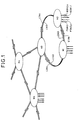
La figure 1 représente une vue d'ensemble d'un réseau selon l'invention.FIG. 1 represents an overall view of a network according to the invention.
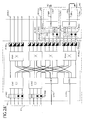
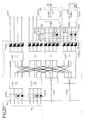
Les figures 2A, 2B et 26 représentent des vues de trois noeuds de ce réseau.FIGS. 2A, 2B and 26 represent views of three nodes of this network.
Il doit être compris que de tels noeuds comportent en pratique de nombreux organes autres que ceux qui ont été représentés et décrits ci-après dans le seul but de faire comprendre l'invention.It should be understood that such nodes include in practice many organs other than those which have been shown and described below for the sole purpose of making the invention understood.
Dans le seul but de simplifier la description ces trois noeuds N1, N2, N3 sont supposés être mutuellement identiques, de même que les trois matrices de commutation M1, M2, M3 qu'ils constituent. Lorsque deux organes appartenant à deux matrices différentes sont identiques et identiquement disposés ils sont désignés par les mêmes signes de référence sauf quant au premier chiffre après les lettres qui, pour chaque organe, est celui qui désigne la matrice à laquelle cet organe appartient. Par exemple un distributeur passif de la matrice M1 est désigné par la référence C1A2, le distributeur correspondant de la matrice M3 étant désigné par le signe de référence C3A2, le chiffre 2 après la deuxième lettre constituée par un A, un B ou un C indiquant qu'il s'agit dans les deux cas d'un deuxième distributeur. Quand le signe de référence d'un organe commence par une lettre et comporte trois chiffres, ce qui est le cas de l'émetteur E1A2,4 les premier et deuxième chiffres tel que 1 et 2 désignent respectivement la matrice et un groupe auxquels cet organe appartient et le troisième chiffre désigne un rang de cet organe dans ce groupe.For the sole purpose of simplifying the description, these three nodes N1, N2, N3 are assumed to be mutually identical, as are the three switching matrices M1, M2, M3 which they constitute. When two organs belonging to two different matrices are identical and identically arranged they are designated by the same reference signs except for the first digit after the letters which, for each organ, is that which designates the matrix to which this organ belongs. For example, a passive distributor of the matrix M1 is designated by the reference C1A2, the corresponding distributor of the matrix M3 being designated by the reference sign C3A2, the number 2 after the second letter consisting of an A, B or C indicating that in both cases it is a second distributor. When the reference sign of an organ begins with a letter and has three digits, which is the case of the transmitter E1A2,4 the first and second digits such as 1 and 2 respectively denote the matrix and a group to which this organ belongs and the third digit designates a rank of this organ in this group.
Conformément à la figure 2B notamment au moins ledit groupe de distributeurs actifs (X2A1...X2A4) et ledit ensemble de filtres (F2A1, 1, F2A4, 4) de ladite matrice éclatée (M2) sont contenus dans un dit noeud (N2) associé à cette matrice, cette matrice éclatée comportant :
- un ensemble d'émetteurs (E2A1,1...,E2A4,4) constitué par une succession de groupes d'émetteurs (GE2A1...GE2A4) dans laquelle ces groupes ont des rangs respectifs (1...4), chaque dit groupe d'émetteurs (GE2A1) étant constitué d'émetteurs (E2A1,1...E2A1,4) se succèdant et ayant des rangs respectifs (1...4) dans ce groupe, chaque dit émetteur étant muni d'une entrée (P2A1,1...P2A1,4) de même rang pour recevoir une dite information, cette entrée constituant une entrée de ladite matrice éclatée (M2), cet émetteur étant piloté par cette information pour émettre une onde optique portant cette information et présentant une dite longueur d'onde porteuse constituant une longueur d'onde de cet émetteur,
- un groupe de distributeurs passifs (C2A1, ..C2A4) formant une succession dans laquelle ces distributeurs ont des rangs respectifs (1...4), chaque dit distributeur passif (C2A1) comportant une succession d'entrées (1C2A1...4C2A1) ayant des rangs (1....4) dans cette succession et raccordées chacune à l'émetteur qui a le même rang que cette entrée et qui appartient au groupe d'émetteurs de même rang que ce distributeur, ce distributeur formant un mélange de toutes ces ondes et comportant encore des sorties (C2A1,1...C2A1,4), transmettant chacune un groupe d'ondes constitué par une fraction de ce mélange,
- et un groupe de distributeurs actifs (X2A1...X2A4) se succèdant en ayant des rangs respectifs (1...4) dans ce groupe, chacun de ces distributeurs actifs (X2A1) comportant une succession d'entrées (1X2A1...4X2A1) ayant des rangs (1...4) dans cette succession et raccordées chacune à une sortie d'un dit distributeur passif ayant le même rang que cette entrée, chacun de ces distributeurs actifs comportant encore une succession de sorties (X2A1,1...X2A1,4) dans laquelle ces sorties ont des rangs respectifs (1...4), ce distributeur actif étant commandé lorsqu'il reçoit un dit groupe d'ondes optiques sur une de ses entrées pour sélectionner au moins une de ses dites sorties et pour transmettre ce groupe d'ondes optiques par sa dite sortie sélectionnée,
- un ensemble de filtres (F2A1,1...F2A4,4) constitué par une succession de groupes de filtres (GF2A1...GF2A4) dans laquelle ces groupes ont des rangs respectifs (1...4), chaque dit groupe de filtres (GF2A1) étant constitué de filtres (F2A1,1...F2A1,4) se succèdant et ayant des rangs respectifs (1...4) dans ce groupe, chacun des filtres (F2A1,1) de ce groupe étant raccordé à une sortie ayant le même rang que ce filtre et appartenant à un dit distributeur actif (X2A1) ayant le même rang que ce groupe, chacun de ces filtres ayant une longueur d'onde commandée constituée par une dite longueur d'onde porteuse, et alimentant une dite sortie (Q2A1, 1) de ladite matrice éclatée (M2) pour transmettre sélectivement en sortie de cette matrice des ondes dont la longueur d'onde est celle de ce filtre, certains au moins desdits distributeurs passifs de cette matrice éclatée constituant des distributeurs éclatés (C2A3, C2A4), chaque dit distributeur éclaté (C2A3) comportant deux parties séparées constituant l'une un multiplexeur spectral (C2B3), l'autre un démultiplexeur (C2C3) et reliées par une dite fibre de liaison (L2A3) associée à ce distributeur éclaté, ce démultiplexeur (C2C3) constituant une partie résidente de ladite matrice éclatée incluse dans ledit noeud (N2) associé à cette matrice (M2), ce multiplexeur (C2B3) et ledit groupe d'émetteurs (GE2A3) raccordés à ce multiplexeur constituant une partie exilée de cette matrice éclatée, cette partie exilée étant incluse dans un noeud d'accueil (N1) associé à une dite matrice composite (M1), ce noeud d'accueil étant constitué par un dit noeud raccordé directement par la dite fibre de liaison (L23A) au noeud (N2) associé à ladite matrice éclatée (M2), les émetteurs (E2A3, 1...E2A3, 4) inclus dans cette partie exilée étant alimentés électriquement par des entrées (P2A3,1) (voir figure 2A) munies de moyens de détection et d'amplification et alimentées optiquement par desdits filtres inclus dans ledit noeud d'accueil (N1), ledit multiplexeur (C2B3) comportant d'une part une succession d'entrées (1C2A3...4C2A3) constituant ladite succession d'entrées de ce distributeur éclaté (C2A3), ce multiplexeur comportant d'autre part une sortie (C2B3L) constituant une dite sortie de liaison de ce noeud associé (N2), ce démultiplexeur (C2C3) (voir figure 2B) comportant d'une part une entrée (C2C3L) constituant une dite entrée de liaison de ce noeud associé, d'autre part une succession de sorties (C2A3,1...C2A3,4) constituant ladite succession de sorties de ce distributeur éclaté, ladite sortie (C2B3L) du multiplexeur étant raccordée à ladite entrée (C2C3L) du démultiplexeur par ladite fibre de liaison (L2A3) associée à ce distributeur éclaté, de manière que plusieurs dites informations soient transmises simultanément par cette fibre avec multiplexage en longueurs d'onde entre ledit noeud associé (N2) et ledit noeud d'accueil (N1).
- a set of transmitters (E2A1,1 ..., E2A4,4) constituted by a succession of groups of transmitters (GE2A1 ... GE2A4) in which these groups have respective ranks (1 ... 4), each said group of transmitters (GE2A1) being made up of transmitters (E2A1,1 ... E2A1,4) succeeding each other and having respective ranks (1 ... 4) in this group, each said transmitter being provided with an input (P2A1,1 ... P2A1,4) of the same rank to receive said information, this input constituting an input of said exploded matrix (M2), this transmitter being controlled by this information to emit an optical wave carrying this information and having a said carrier wavelength constituting a wavelength of this transmitter,
- a group of passive distributors (C2A1, ..C2A4) forming a succession in which these distributors have respective rows (1 ... 4), each said passive distributor (C2A1) comprising a succession of inputs (1C2A1 ... 4C2A1 ) having rows (1 .... 4) in this succession and connected each to the transmitter which has the same rank as this input and which belongs to the group of transmitters of the same rank as this distributor, this distributor forming a mixture of all these waves and still having outputs (C2A1,1 ... C2A1 , 4), each transmitting a group of waves consisting of a fraction of this mixture,
- and a group of active distributors (X2A1 ... X2A4) succeeding each other having respective ranks (1 ... 4) in this group, each of these active distributors (X2A1) comprising a succession of inputs (1X2A1 ... 4X2A1) having rows (1 ... 4) in this succession and each connected to an output of a said passive distributor having the same rank as this input, each of these active distributors still comprising a succession of outputs (X2A1,1 ... X2A1,4) in which these outputs have respective rows (1 ... 4), this active distributor being controlled when it receives a said group of optical waves on one of its inputs to select at least one of its said outputs and to transmit this group of optical waves by its said selected output,
- a set of filters (F2A1,1 ... F2A4,4) constituted by a succession of groups of filters (GF2A1 ... GF2A4) in which these groups have respective ranks (1 ... 4), each said group of filters (GF2A1) consisting of successive filters (F2A1,1 ... F2A1,4) and having respective rows (1 ... 4) in this group, each of the filters (F2A1,1) in this group being connected to an output having the same rank as this filter and belonging to a said active distributor (X2A1) having the same rank as this group, each of these filters having a controlled wavelength constituted by a said carrier wavelength, and supplying a said output (Q2A1, 1) of said exploded matrix (M2) for selectively transmitting at the output of this matrix waves whose wavelength is that of this filter, at least some of said passive distributors of this exploded matrix constituting exploded distributors (C2A3, C2A4), each said exploded distributor (C2A3) comprising two separate parts constituting one of a spectral multiplexer (C2B3), the other a demultiplexer (C2C3) and connected by a said connecting fiber (L2A3) associated with this exploded distributor, this demultiplexer (C2C3) constituting a resident part of said exploded matrix included in said node (N2) associated with this matrix (M2), this multiplexer (C2B3) and said group of transmitters (GE2A3) connected to this multiplexer constituting an exiled part of this exploded matrix, this exiled part being included in a reception node (N1) associated with a so-called composite matrix (M1), this reception node being constituted by a said node directly connected by said connecting fiber (L23A ) at the node (N2) associated with said exploded matrix (M2), the transmitters (E2A3, 1 ... E2A3, 4) included in this exiled part being electrically supplied by inputs (P2A3,1) (see FIG. 2A) provided means of d tection and amplification and optically fed by said filters included in said reception node (N1), said multiplexer (C2B3) comprising on the one hand a succession of inputs (1C2A3 ... 4C2A3) constituting said succession of inputs of this exploded distributor (C2A3), this multiplexer comprising on the other hand an output (C2B3L) constituting a said connection output of this associated node (N2), this demultiplexer (C2C3) (see FIG. 2B) comprising on the one hand input (C2C3L) constituting a said connection input of this associated node, on the other hand a succession of outputs (C2A3,1 ... C2A3,4) constituting said succession of outputs of this exploded distributor, said output (C2B3L) of the multiplexer being connected to said input (C2C3L) of the demultiplexer by said connecting fiber (L2A3) associated with this exploded distributor, so that several said pieces of information are transmitted simultaneously by this fiber with wavelength multiplexing between said associated node (N2) and said reception node (N1).
De préférence ledit noeud (N2) associé à ladite matrice éclatée (M2) est un noeud à accès local. Le groupe de distributeurs passifs (C2A1...C2A4) de cette matrice comporte alors en outre pour cela au moins un distributeur passif entièremement inclus dans ce noeud et constituant un distributeur intégré (C2A1, C2A2).Preferably said node (N2) associated with said exploded matrix (M2) is a node with local access. The group of passive distributors (C2A1 ... C2A4) of this matrix then further comprises, for this purpose, at least one passive distributor entirely included in this node and constituting an integrated distributor (C2A1, C2A2).
De préférence aussi ladite matrice éclatée (M2) comporte plusieurs distributeurs éclatés (C2A3, C2A4) formant plusieurs parties exilées (C2B3, fig 2A, C2B4, fig 2C) incluses dans plusieurs noeuds d'accueil (N1, N3) raccordés directement à cette matrice éclatée par plusieurs fibres de liaison (L2A3, L2A4), respectivement.Preferably also said exploded matrix (M2) comprises several exploded distributors (C2A3, C2A4) forming several exiled parts (C2B3, fig 2A, C2B4, fig 2C) included in several reception nodes (N1, N3) connected directly to this matrix split by several connecting fibers (L2A3, L2A4), respectively.
De préférence enfin le réseau comporte au moins deux matrices éclatées (M1, M2) et deux noeuds (N1, N2) associés respectivement à ces deux matrices, et au moins deux fibres de liaison (L2A3, L1A4) transmettant desdites informations entre ces deux noeuds dans deux directions opposées.Preferably, finally, the network comprises at least two exploded matrices (M1, M2) and two nodes (N1, N2) associated respectively with these two matrices, and at least two connecting fibers (L2A3, L1A4) transmitting said information between these two nodes in two opposite directions.
Claims (5)
Applications Claiming Priority (2)
| Application Number | Priority Date | Filing Date | Title |
|---|---|---|---|
| FR9212018 | 1992-10-09 | ||
| FR9212018A FR2696891B1 (en) | 1992-10-09 | 1992-10-09 | Optical switching matrix. |
Publications (2)
| Publication Number | Publication Date |
|---|---|
| EP0592330A1 true EP0592330A1 (en) | 1994-04-13 |
| EP0592330B1 EP0592330B1 (en) | 1999-05-26 |
Family
ID=9434330
Family Applications (2)
| Application Number | Title | Priority Date | Filing Date |
|---|---|---|---|
| EP93402513A Expired - Lifetime EP0592331B1 (en) | 1992-10-09 | 1993-10-11 | Optical switching matrix |
| EP93402512A Expired - Lifetime EP0592330B1 (en) | 1992-10-09 | 1993-10-11 | Optical transmission network with switching matrix |
Family Applications Before (1)
| Application Number | Title | Priority Date | Filing Date |
|---|---|---|---|
| EP93402513A Expired - Lifetime EP0592331B1 (en) | 1992-10-09 | 1993-10-11 | Optical switching matrix |
Country Status (9)
| Country | Link |
|---|---|
| US (2) | US5485297A (en) |
| EP (2) | EP0592331B1 (en) |
| JP (2) | JPH07502157A (en) |
| AT (2) | ATE180617T1 (en) |
| CA (2) | CA2124463A1 (en) |
| DE (2) | DE69325067T2 (en) |
| ES (2) | ES2132206T3 (en) |
| FR (1) | FR2696891B1 (en) |
| WO (2) | WO1994009601A1 (en) |
Cited By (2)
| Publication number | Priority date | Publication date | Assignee | Title |
|---|---|---|---|---|
| FR2739942A1 (en) * | 1995-10-13 | 1997-04-18 | Cit Alcatel | Optical add-drop spectral multiplexer |
| US6262821B1 (en) | 1996-10-18 | 2001-07-17 | Alcatel Cit | Optical spectral multiplexer for inserting and extracting |
Families Citing this family (21)
| Publication number | Priority date | Publication date | Assignee | Title |
|---|---|---|---|---|
| US5485297A (en) * | 1992-10-09 | 1996-01-16 | Alcatel N.V. | Optical switching matrix |
| US5815295A (en) * | 1993-03-11 | 1998-09-29 | Lucent Technologies Inc. | Optical communication system with improved maintenance capabilities |
| DE69424311T2 (en) * | 1993-11-08 | 2000-12-14 | British Telecomm | CROSS-CONNECTING SYSTEM FOR AN OPTICAL NETWORK |
| FR2735638B1 (en) * | 1995-06-14 | 1997-07-11 | Cit Alcatel | HIGH CAPACITY ASYNCHRONOUS TRANSFER SWITCHING MATRIX |
| FR2743424B1 (en) * | 1996-01-09 | 1998-03-27 | Instruments Sa | WAVELENGTH ROUTER N X N, OPTICAL ROUTING PROCESS AND ASSOCIATED COMMUNICATIONS NETWORK |
| FR2743430A1 (en) * | 1996-01-09 | 1997-07-11 | Instruments Sa | Switching matrix router for optical communications networks |
| US5943150A (en) * | 1996-09-30 | 1999-08-24 | Regents Of The University Of California | Massively parallel processor networks with optical express channels |
| AU5079998A (en) | 1996-10-15 | 1998-05-22 | Regents Of The University Of California, The | High-performance parallel processors based on star-coupled wavelength division multiplexing optical interconnects |
| JPH10164022A (en) * | 1996-12-04 | 1998-06-19 | Nec Corp | Submarine branching device |
| US6125228A (en) * | 1998-03-04 | 2000-09-26 | Swales Aerospace, Inc. | Apparatus for beam splitting, combining wavelength division multiplexing and demultiplexing |
| US6614781B1 (en) | 1998-11-20 | 2003-09-02 | Level 3 Communications, Inc. | Voice over data telecommunications network architecture |
| US6647208B1 (en) * | 1999-03-18 | 2003-11-11 | Massachusetts Institute Of Technology | Hybrid electronic/optical switch system |
| US7145704B1 (en) * | 2003-11-25 | 2006-12-05 | Cheetah Omni, Llc | Optical logic gate based optical router |
| CA2451858A1 (en) * | 2001-06-25 | 2003-01-03 | Corvis Corporation | Optical transmission systems, devices, and methods |
| US7110671B1 (en) * | 2001-12-03 | 2006-09-19 | Cheetah Omni, Llc | Method and apparatus for scheduling communication using a star switching fabric |
| US7209657B1 (en) | 2001-12-03 | 2007-04-24 | Cheetah Omni, Llc | Optical routing using a star switching fabric |
| US7034975B1 (en) | 2001-12-03 | 2006-04-25 | Cheetah Onmi, Llc | High speed MEMS device |
| US7260655B1 (en) | 2001-12-03 | 2007-08-21 | Cheetah Omni, Llc | Optical routing using star switching fabric with reduced effective switching time |
| US7324922B2 (en) * | 2005-10-26 | 2008-01-29 | International Business Machines Corporation | Run-time performance verification system |
| JP5267191B2 (en) * | 2009-02-18 | 2013-08-21 | 富士通株式会社 | Optical ring network system and optical transmission device |
| CN107797181B (en) * | 2016-08-31 | 2020-04-28 | 华为技术有限公司 | Optical switch matrix and control method thereof |
Citations (2)
| Publication number | Priority date | Publication date | Assignee | Title |
|---|---|---|---|---|
| WO1992010770A1 (en) * | 1990-12-07 | 1992-06-25 | Telefonaktiebolaget Lm Ericsson | A method and arrangement for optical switching |
| EP0492852A2 (en) * | 1990-12-28 | 1992-07-01 | AT&T Corp. | Optical packet switch |
Family Cites Families (6)
| Publication number | Priority date | Publication date | Assignee | Title |
|---|---|---|---|---|
| NL8502665A (en) * | 1985-09-30 | 1987-04-16 | Philips Nv | BROADBAND OPTICAL DISTRIBUTION SYSTEM. |
| US4873681A (en) * | 1988-01-26 | 1989-10-10 | Bell Communications Research, Inc. | Hybrid optical and electronic packet switch |
| GB8902746D0 (en) * | 1989-02-08 | 1989-03-30 | British Telecomm | Communications network |
| JPH04334134A (en) * | 1991-05-10 | 1992-11-20 | Mitsubishi Electric Corp | Optical communication equipment |
| FR2683962B1 (en) * | 1991-11-19 | 1994-03-25 | Lecoquil Emile | OPTICAL DISTRIBUTOR. |
| US5485297A (en) * | 1992-10-09 | 1996-01-16 | Alcatel N.V. | Optical switching matrix |
-
1992
- 1992-10-09 US US08/244,610 patent/US5485297A/en not_active Expired - Lifetime
- 1992-10-09 FR FR9212018A patent/FR2696891B1/en not_active Expired - Fee Related
-
1993
- 1993-10-11 CA CA002124463A patent/CA2124463A1/en not_active Abandoned
- 1993-10-11 ES ES93402513T patent/ES2132206T3/en not_active Expired - Lifetime
- 1993-10-11 EP EP93402513A patent/EP0592331B1/en not_active Expired - Lifetime
- 1993-10-11 DE DE69325067T patent/DE69325067T2/en not_active Expired - Lifetime
- 1993-10-11 ES ES93402512T patent/ES2132205T3/en not_active Expired - Lifetime
- 1993-10-11 DE DE69325068T patent/DE69325068T2/en not_active Expired - Lifetime
- 1993-10-11 AT AT93402512T patent/ATE180617T1/en not_active IP Right Cessation
- 1993-10-11 JP JP6509701A patent/JPH07502157A/en active Pending
- 1993-10-11 WO PCT/FR1993/001005 patent/WO1994009601A1/en active Application Filing
- 1993-10-11 AT AT93402513T patent/ATE180618T1/en not_active IP Right Cessation
- 1993-10-11 EP EP93402512A patent/EP0592330B1/en not_active Expired - Lifetime
- 1993-10-11 JP JP50970094A patent/JP3394255B2/en not_active Expired - Lifetime
- 1993-10-11 US US08/244,624 patent/US5537239A/en not_active Expired - Lifetime
- 1993-10-11 CA CA002117301A patent/CA2117301A1/en not_active Abandoned
- 1993-10-11 WO PCT/FR1993/001006 patent/WO1994009602A1/en active Application Filing
Patent Citations (2)
| Publication number | Priority date | Publication date | Assignee | Title |
|---|---|---|---|---|
| WO1992010770A1 (en) * | 1990-12-07 | 1992-06-25 | Telefonaktiebolaget Lm Ericsson | A method and arrangement for optical switching |
| EP0492852A2 (en) * | 1990-12-28 | 1992-07-01 | AT&T Corp. | Optical packet switch |
Non-Patent Citations (7)
| Title |
|---|
| A.M. HILL: "A Distributed Wavelength Switching Architecture for the TPON Local Network", PROCEEDINGS, INTERNATIONAL SWITCHING SYMPOSIUM, 27 MAI-1 JUIN 1990, VOL.III PAGES 21-26, STOCKHOLM SE, XP000130869 * |
| C.A. BRACKETT: "Dense Wavelength Division Multiplexing Networks: Principles and Applications", IEEE JOURNAL ON SELECTED AREAS IN COMMUNICATION, vol. 8, no. 6, August 1990 (1990-08-01), NEW YORK US, pages 948 - 964, XP000208590 * |
| G.R.HILL: "A Wavelength Routing Approach to Optical Communications Networks", PROCEEDINGS, IEEE CONFERENCE ON COMPUTER COMMUNICATIONS (INFOCOM '88), 27-28 MARS 1988, PAGES 354-361, NEW ORLEANS US, XP000044787 * |
| H. KOBRINSKI ET AL: "Demonstration of High Capacity in the Lambdanet Architecture: a Multiwavelength Optical Network", ELECTRONICS LETTERS, vol. 23, no. 16, 30 July 1987 (1987-07-30), STEVENAGE GB, pages 824 - 826, XP000796980 * |
| H. OBARA ET AL: "Star Coupler Based WDM Switch Employing Tunable Device with Reduced Tunability Range", ELECTRONICS LETTERS, vol. 28, no. 13, 18 June 1992 (1992-06-18), STEVENAGE GB, pages 1268 - 1270, XP000301528 * |
| M. FUJIWARA ET AL: "Line Capacity Expansion Schemes in Photonic Switching", IEEE TRANSACTIONS ON PARALLEL AND DISTRIBUTED SYSTEMS, vol. 1, no. 2, May 1990 (1990-05-01), NEW YORK US, pages 47 - 53, XP000128311 * |
| R.P. MARSDEN ET AL: "Digital Television Routing Systems: a Survey of Optical and Electrical Techniques", BBC RESEARCH DEPARTMENT REPORT, no. 3, March 1988 (1988-03-01), TADWORTH GB, pages 1 - 31, XP000815186 * |
Cited By (3)
| Publication number | Priority date | Publication date | Assignee | Title |
|---|---|---|---|---|
| FR2739942A1 (en) * | 1995-10-13 | 1997-04-18 | Cit Alcatel | Optical add-drop spectral multiplexer |
| WO1998018231A1 (en) * | 1995-10-13 | 1998-04-30 | Alcatel Cit | Optical spectral multiplexer for inserting and extracting |
| US6262821B1 (en) | 1996-10-18 | 2001-07-17 | Alcatel Cit | Optical spectral multiplexer for inserting and extracting |
Also Published As
| Publication number | Publication date |
|---|---|
| EP0592331A1 (en) | 1994-04-13 |
| WO1994009601A1 (en) | 1994-04-28 |
| EP0592331B1 (en) | 1999-05-26 |
| FR2696891B1 (en) | 1994-11-04 |
| DE69325067T2 (en) | 1999-10-21 |
| EP0592330B1 (en) | 1999-05-26 |
| ATE180618T1 (en) | 1999-06-15 |
| ES2132206T3 (en) | 1999-08-16 |
| JP3394255B2 (en) | 2003-04-07 |
| FR2696891A1 (en) | 1994-04-15 |
| CA2124463A1 (en) | 1994-04-28 |
| WO1994009602A1 (en) | 1994-04-28 |
| ATE180617T1 (en) | 1999-06-15 |
| US5537239A (en) | 1996-07-16 |
| DE69325067D1 (en) | 1999-07-01 |
| DE69325068D1 (en) | 1999-07-01 |
| CA2117301A1 (en) | 1994-04-28 |
| JPH07502156A (en) | 1995-03-02 |
| US5485297A (en) | 1996-01-16 |
| DE69325068T2 (en) | 1999-10-21 |
| ES2132205T3 (en) | 1999-08-16 |
| JPH07502157A (en) | 1995-03-02 |
Similar Documents
| Publication | Publication Date | Title |
|---|---|---|
| EP0592330B1 (en) | Optical transmission network with switching matrix | |
| EP2141842B1 (en) | Optical signal switching device | |
| EP0687085B1 (en) | Optical drop/insert multiplexer | |
| US6404948B2 (en) | Dense WDM optical multiplexer and demultiplexer | |
| FR2718908A1 (en) | Telecommunication network organized in reconfigurable multicolored optical loops. | |
| FR2715015A1 (en) | Method and device for transmitting and routing packets in an optical network | |
| FR2759834A1 (en) | RECONFIGURABLE RING TRANSMISSION NETWORK WITH WAVELENGTH MULTIPLEXING FOR SEMI-PERMANENT LINKS | |
| EP0677935A1 (en) | Ring network architecture for multiple access transmission by means of spectral routing | |
| EP0543714B1 (en) | Optical fibre distribution apparatus | |
| US6744986B1 (en) | Tunable wavelength add/drop multiplexer based on integrated optic devices | |
| EP0697800B1 (en) | Optical crossconnector | |
| FR2933256A1 (en) | Optical signal switching device for meshed transparent wavelength division multiplexing optical network, has optical connectors broadcasting optical incoming signal received by broadcast couplers, towards selective switches, simultaneously | |
| FR2830709A1 (en) | Reconfigurable optical switching system for frequency division multiplex system, includes optical switches to selectively and respectively connect output port of demultiplexer to input port of multiplexer | |
| US6539149B1 (en) | Waveguide grating router employing transmissive Echelle gratings | |
| FR2736480A1 (en) | COLORING DEVICE FOR OPTICAL SIGNALS | |
| EP1076470B1 (en) | Hybrid space and wavelength selector and optical switching matrix containing such selectors | |
| FR2722044A1 (en) | OPTICAL INTERCONNECTION SYSTEM | |
| FR2739942A1 (en) | Optical add-drop spectral multiplexer | |
| FR2752119A1 (en) | Cross-coupled optical fibre connector for communication network | |
| FR2821504A1 (en) | FREQUENCY EXTRACTION DEVICE | |
| EP1379100B1 (en) | Optical cross-connect with multigranular architecture | |
| EP2282430B1 (en) | Device for multipath dropping of WDM channels | |
| EP1804407B1 (en) | Acces node for optical ring network | |
| FR2844955A1 (en) | MULTIGRANULAR ARCHITECTURE OPTICAL BURNER | |
| EP2007049B1 (en) | Device for transmitting multi-rate optical signals |
Legal Events
| Date | Code | Title | Description |
|---|---|---|---|
| PUAI | Public reference made under article 153(3) epc to a published international application that has entered the european phase |
Free format text: ORIGINAL CODE: 0009012 |
|
| AK | Designated contracting states |
Kind code of ref document: A1 Designated state(s): AT BE CH DE ES FR GB IT LI NL SE |
|
| 17P | Request for examination filed |
Effective date: 19940705 |
|
| 17Q | First examination report despatched |
Effective date: 19970509 |
|
| GRAG | Despatch of communication of intention to grant |
Free format text: ORIGINAL CODE: EPIDOS AGRA |
|
| GRAG | Despatch of communication of intention to grant |
Free format text: ORIGINAL CODE: EPIDOS AGRA |
|
| GRAH | Despatch of communication of intention to grant a patent |
Free format text: ORIGINAL CODE: EPIDOS IGRA |
|
| GRAH | Despatch of communication of intention to grant a patent |
Free format text: ORIGINAL CODE: EPIDOS IGRA |
|
| GRAA | (expected) grant |
Free format text: ORIGINAL CODE: 0009210 |
|
| RAP1 | Party data changed (applicant data changed or rights of an application transferred) |
Owner name: ALCATEL |
|
| AK | Designated contracting states |
Kind code of ref document: B1 Designated state(s): AT BE CH DE ES FR GB IT LI NL SE |
|
| REF | Corresponds to: |
Ref document number: 180617 Country of ref document: AT Date of ref document: 19990615 Kind code of ref document: T |
|
| ITF | It: translation for a ep patent filed |
Owner name: JACOBACCI & PERANI S.P.A. |
|
| REG | Reference to a national code |
Ref country code: CH Ref legal event code: EP |
|
| GBT | Gb: translation of ep patent filed (gb section 77(6)(a)/1977) |
Effective date: 19990526 |
|
| REF | Corresponds to: |
Ref document number: 69325067 Country of ref document: DE Date of ref document: 19990701 |
|
| REG | Reference to a national code |
Ref country code: ES Ref legal event code: FG2A Ref document number: 2132205 Country of ref document: ES Kind code of ref document: T3 |
|
| PG25 | Lapsed in a contracting state [announced via postgrant information from national office to epo] |
Ref country code: LI Free format text: LAPSE BECAUSE OF NON-PAYMENT OF DUE FEES Effective date: 19991031 Ref country code: CH Free format text: LAPSE BECAUSE OF NON-PAYMENT OF DUE FEES Effective date: 19991031 Ref country code: BE Free format text: LAPSE BECAUSE OF NON-PAYMENT OF DUE FEES Effective date: 19991031 |
|
| PLBE | No opposition filed within time limit |
Free format text: ORIGINAL CODE: 0009261 |
|
| STAA | Information on the status of an ep patent application or granted ep patent |
Free format text: STATUS: NO OPPOSITION FILED WITHIN TIME LIMIT |
|
| BERE | Be: lapsed |
Owner name: ALCATEL Effective date: 19991031 |
|
| 26N | No opposition filed | ||
| REG | Reference to a national code |
Ref country code: CH Ref legal event code: PL |
|
| REG | Reference to a national code |
Ref country code: GB Ref legal event code: IF02 |
|
| PGFP | Annual fee paid to national office [announced via postgrant information from national office to epo] |
Ref country code: NL Payment date: 20030930 Year of fee payment: 11 |
|
| PGFP | Annual fee paid to national office [announced via postgrant information from national office to epo] |
Ref country code: SE Payment date: 20031001 Year of fee payment: 11 Ref country code: AT Payment date: 20031001 Year of fee payment: 11 |
|
| PGFP | Annual fee paid to national office [announced via postgrant information from national office to epo] |
Ref country code: ES Payment date: 20031017 Year of fee payment: 11 |
|
| PG25 | Lapsed in a contracting state [announced via postgrant information from national office to epo] |
Ref country code: AT Free format text: LAPSE BECAUSE OF NON-PAYMENT OF DUE FEES Effective date: 20041011 |
|
| PG25 | Lapsed in a contracting state [announced via postgrant information from national office to epo] |
Ref country code: SE Free format text: LAPSE BECAUSE OF NON-PAYMENT OF DUE FEES Effective date: 20041012 |
|
| PG25 | Lapsed in a contracting state [announced via postgrant information from national office to epo] |
Ref country code: ES Free format text: LAPSE BECAUSE OF NON-PAYMENT OF DUE FEES Effective date: 20041013 |
|
| PG25 | Lapsed in a contracting state [announced via postgrant information from national office to epo] |
Ref country code: NL Free format text: LAPSE BECAUSE OF NON-PAYMENT OF DUE FEES Effective date: 20050501 |
|
| EUG | Se: european patent has lapsed | ||
| NLV4 | Nl: lapsed or anulled due to non-payment of the annual fee |
Effective date: 20050501 |
|
| REG | Reference to a national code |
Ref country code: ES Ref legal event code: FD2A Effective date: 20041013 |
|
| REG | Reference to a national code |
Ref country code: FR Ref legal event code: CD |
|
| PGFP | Annual fee paid to national office [announced via postgrant information from national office to epo] |
Ref country code: DE Payment date: 20121023 Year of fee payment: 20 Ref country code: FR Payment date: 20121031 Year of fee payment: 20 |
|
| PGFP | Annual fee paid to national office [announced via postgrant information from national office to epo] |
Ref country code: GB Payment date: 20121019 Year of fee payment: 20 Ref country code: IT Payment date: 20121026 Year of fee payment: 20 |
|
| REG | Reference to a national code |
Ref country code: DE Ref legal event code: R071 Ref document number: 69325067 Country of ref document: DE |
|
| REG | Reference to a national code |
Ref country code: DE Ref legal event code: R071 Ref document number: 69325067 Country of ref document: DE |
|
| REG | Reference to a national code |
Ref country code: GB Ref legal event code: PE20 Expiry date: 20131010 |
|
| REG | Reference to a national code |
Ref country code: GB Ref legal event code: 732E Free format text: REGISTERED BETWEEN 20131114 AND 20131120 |
|
| PG25 | Lapsed in a contracting state [announced via postgrant information from national office to epo] |
Ref country code: GB Free format text: LAPSE BECAUSE OF EXPIRATION OF PROTECTION Effective date: 20131010 Ref country code: DE Free format text: LAPSE BECAUSE OF EXPIRATION OF PROTECTION Effective date: 20131012 |
|
| REG | Reference to a national code |
Ref country code: FR Ref legal event code: GC Effective date: 20140717 |
|
| REG | Reference to a national code |
Ref country code: FR Ref legal event code: RG Effective date: 20141016 |