EP0591966B1 - Endoluminal ultrasonic device and its application - Google Patents
Endoluminal ultrasonic device and its application Download PDFInfo
- Publication number
- EP0591966B1 EP0591966B1 EP93116239A EP93116239A EP0591966B1 EP 0591966 B1 EP0591966 B1 EP 0591966B1 EP 93116239 A EP93116239 A EP 93116239A EP 93116239 A EP93116239 A EP 93116239A EP 0591966 B1 EP0591966 B1 EP 0591966B1
- Authority
- EP
- European Patent Office
- Prior art keywords
- electronics
- catheter
- probe
- drive
- catheter sheath
- Prior art date
- Legal status (The legal status is an assumption and is not a legal conclusion. Google has not performed a legal analysis and makes no representation as to the accuracy of the status listed.)
- Expired - Lifetime
Links
Images


Classifications
-
- A—HUMAN NECESSITIES
- A61—MEDICAL OR VETERINARY SCIENCE; HYGIENE
- A61B—DIAGNOSIS; SURGERY; IDENTIFICATION
- A61B8/00—Diagnosis using ultrasonic, sonic or infrasonic waves
- A61B8/12—Diagnosis using ultrasonic, sonic or infrasonic waves in body cavities or body tracts, e.g. by using catheters
-
- A—HUMAN NECESSITIES
- A61—MEDICAL OR VETERINARY SCIENCE; HYGIENE
- A61B—DIAGNOSIS; SURGERY; IDENTIFICATION
- A61B8/00—Diagnosis using ultrasonic, sonic or infrasonic waves
- A61B8/44—Constructional features of the ultrasonic, sonic or infrasonic diagnostic device
- A61B8/4444—Constructional features of the ultrasonic, sonic or infrasonic diagnostic device related to the probe
- A61B8/445—Details of catheter construction
-
- A—HUMAN NECESSITIES
- A61—MEDICAL OR VETERINARY SCIENCE; HYGIENE
- A61B—DIAGNOSIS; SURGERY; IDENTIFICATION
- A61B8/00—Diagnosis using ultrasonic, sonic or infrasonic waves
- A61B8/44—Constructional features of the ultrasonic, sonic or infrasonic diagnostic device
- A61B8/4405—Device being mounted on a trolley
Definitions
- the invention relates to a endoluminal ultrasound machine according to the preamble of claim 1.
- This device has a single rotating ultrasonic transducer or an ultrasonic reflector at the end of the flexible stationary Catheter.
- the transducer element or reflector rotates around the catheter and thus carries out a scan perpendicular to the catheter axis.
- Another type of device is an endoluminal ultrasound device several stationary ultrasound transducer elements around the periphery at the end a flexible stationary catheter.
- the converter elements are activated sequentially in groups to perform a scan in a simple vertical plane to the catheter axis.
- This type of device has been described in U.S. Patent 3,938,505. Since he's only on one Plane limited perpendicular to the catheter axis, both described Devices are not a good longitudinal, i.e. Axial resolution on.
- U.S. Patent 5,070,879 describes a manually held transrectal Ultrasound device integrated in a rigid longitudinal housing.
- An ultrasound transducer element array is axially mounted on the housing for the vibrations around the longitudinal axis.
- a catheter for ultrasound image recording is known from WO-A-92/11055, which has a flexible catheter sheath that inside except a guide wire receives a flexible drive shaft, on the distal An ultrasonic transducer probe is located at the end. At its proximal In the end, this drive shaft is connected to a drive motor via a spindle, with the help of the drive shaft and the ultrasonic transducer probe can be rotated. The catheter sheath itself meanwhile remains at rest.
- Ultrasound device in that it has a drive with rotatable Drive shaft that swings back and forth, being flexible Catheter sheath is coupled to a drive end and to the drive shaft swings.
- the catheter sheath has an axis around which the drive shaft swings. The diameter is such that it enters a human blood vessel can be introduced.
- An ultrasound transducer is at the other end integrates and vibrates with the catheter sheath.
- the converter is with one Array of autonomous axially parallel arranged elements and thus forms a beam rotating perpendicular to the axis.
- the converter elements are through controlled electronics near the drive. Based on The leads passed through the catheter sheath are attached to the transducer elements the electronics coupled.
- the electronics successively turn on the converters to get image scans in desired perform different angles around the axis
- the electrical wiring consists of several lines, which individually the Couple transducer elements to the electronics. There is one in electronics electronic beam focusing to improve the axial resolution of the Device integrated.
- the invention enables a method for ultrasound imaging of body cavities.
- An array with along The ultrasound transducer elements arranged on the axis are placed in a blood vessel or inserted into another body cavity with fluid that to be mapped.
- the lines coming out of the array become Control of the array function through the catheter sheath to the electronic Circuits outside the human body.
- the catheter sheath and the transducer array are placed together in the blood vessel or in another body cavity during the operation of the array Vibration is offset to deliver ultrasonic pulses through the liquid to the to deliver surrounding tissue wall.
- the echo signals are processed and output on the display so that the tissue structure surrounding the body cavity can be examined.
- FIG. 1 shows a medical ultrasound imaging system with a console 10 shown.
- the control panel 11 is on the oblique control panel arranged on the left side of the console 10.
- a drive 12 is mounted on the console 10 next to the control panel 11.
- This drive 12 has a hollow rotating drive shaft 14, which is preferably rotates at an angle of 360 °.
- a video output terminal 15 is arranged in front of the control panel 11.
- the proximal end of a flexible Catheter sleeve 16 is connected to the drive shaft 14 and thus set in motion.
- the diameter of the catheter sleeve is designed that it is in a human blood vessel, e.g. with a size of 2.25 mm or in another body cavity with liquid, e.g. the urethra can be inserted.
- An ultrasound transducer probe is connected to the distal end of the catheter sheath 16.
- a signal cable 17 is guided by the drive 12 into the console 10.
- the ultrasonic transducer probe 18 connected to the distate end of the catheter sheath 16.
- the catheter sheath 16 should preferably be a hollow tube 20 made of corrosion-resistant material, e.g. stainless steel with a Outer layer 22 made of low friction material such as Teflon included. Possibly a purchase part available on the market could be used as a catheter be used.
- Several lines 24 run through the catheter sheath 16 from the distal end to the drive 12 on the console 10. The cables 24 run to a plug 26.
- the probe 18 contains an array of electrically isolated ultrasound elements 28 made of piezoceramic.
- a base plate 30 is attached to the rear of the array 28 mounted so that an active surface 32 for the emission of ultrasonic energy arises.
- a printed circuit board 34 is placed behind the base plate 30 mounted. This card 34 is equipped with circuits that be guided to the individual elements 28. For this purpose, in an opening can be made in the base plate 30. Connect the lines 36 the pads on the printed circuit board 34 with a Plug socket into which the plug 22 is inserted.
- the probe 18 has a cylindrical housing made of molded parts 38a, 38b, 38c, 38d, 38e with a rounded distal end and is at the end gradually tapered for connection to the catheter sheath.
- the cast in Parts are interconnected to form the probe housing, as already explained.
- the housing parts 38a, 38b, 38c, 38d are made of biological non-reactive material, e.g. Urethane, the housing part 38e consists of material permeable to ultrasound energy, part 38e is optional; surface 32 could serve as an outer surface of probe 18.
- the plug 38 is attached to the stepped tapered probe housing end, that fits into the hollow distal end of the catheter sheath.
- a sealing ring holder 40 and a pressure seal 42 ensure the securing and the tightness of the interface between the probe 18 and the Catheter sheath 16.
- the active one is Area of the array 3.8 mm x 1.5 mm with a number of elements of 24 plus 3 protection elements at each end.
- the catheter sheath 16 and the probe 18 would have to go into the body cavity the known guidewire techniques are introduced.
- the guide wire then guides the distal end of the catheter sheath 16 and the probe 18 into the Body cavity. It could be inside through the catheter sheath 16 and through a Opening (not visible in the drawing) in the housing of the probe 18 or the catheter sheath 16 and the probe 18 could laterally run along the guide wire.
- the catheter sheath 16 and the probe 18 generally have a smaller one Diameter than the body cavity. Therefore, care must be taken in particular that the distal end of the catheter sheath 16 and the probe 18 are fixed are anchored to back and forth or axial movements in the body cavity to avoid during the examination of the tissue wall.
- a balloon on the distal end of the catheter sleeve 16 after the catheter sheath is inserted into the body cavity. This balloon could either be attached to the catheter sleeve while rotating or attached using ball bearings to keep yourself moving not to turn the catheter sheath.
- Another alternative would be Solution, the distal end of the catheter sheath 16 through another sheath to anchor the space between the distal end of the catheter sheath 16 and the fabric wall fills.
- Lines (24 and 36) vibrate at the distal end of the catheter sheath 16 with sheath 16 and probe 18. At the proximal end of the catheter sheath 16, however, the lines 24 with the stationary housing of the drive 12 connected. Therefore, the lines 24 reciprocate when the Drive 12 is in motion.
- the catheter sleeve 16 is so long that the Rotation per unit length is low. Usually has the catheter sheath a length of 50 - 100 cm and more. To the electrical connection to the cable 17th to ensure the lines 24 could pass through the hollow drive shaft 14 and the drive 12 are performed.
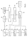
- FIG. 5 is a block diagram of the overall ultrasound imaging system with Drive 12, catheter sheath 16 and probe 18.
- the drive is 12 coupled through the catheter sheath 16 to the probe 18, furthermore it is connected to a position transmitter 50.
- the drive electronics 52 controls the movements of the drive 12 to one of the position transmitter 50 and the converter control electronics 54 command supplied out.
- the probe 18 is electrically connected to a beamformer 56 via lines 36, plug (26 and 38), further lines 24 and a parallel cable 17 connected, the total, as shown in Fig. 5, by the electrical Connection 58 are shown.
- the beam former 56 is used for focusing the transmitted and / or received ultrasonic energy preferably by introducing electrical delays in the signal paths of the array elements.
- the beamformer 56 is on one of the Converter control electronics 54 and the main control unit 60 supplied Command activated, the latter by a command from the control panel 13 is activated.
- the signals for generating the transmission pulse for the probe 18 are generated in the converter control electronics 54 and are therefore via the beam former 56 and the electrical connection unit 58 coupled to the probe 18.
- the electrical generated by the probe 18 Echo signals are via the electrical connection 58 and the Beamformer 56 is supplied to a video processing device 64.
- This Video processing device 64 processes the high-frequency electrical Signals to image signals supplied to a scan converter 66.
- the image signals are stored and used in the scan converter 66 Playback prepared accordingly on a video output terminal 15.
- the main control unit 60 controls the operation of the video processing device 64, scan converter 66 and video output terminal 70 in the usual way Standard procedure.
- the drive 12 can be controlled in this way be that the drive shaft 14 continuously or in certain time intervals moved.
- the imaging depth is at about 3 to 4 cm and the angular speed of the drive 12 at 1 RPM.
- the transducer elements 28 can be controlled successively to make samples parallel to the probe axis 18 at different angles around the Perform axis 18, or simultaneously to execute a single Scanning perpendicular to the probe axis 18 can be controlled when the probe 18 is in motion. If the transducer elements 28 are in a continuous Vibration movement of the probe 18 can be activated successively the 3D data then determined is also three-dimensional on the display being represented.
- the catheter sleeve 16 can be integrated into a non-rotating outer tube instead of directly into the blood vessel, which then results in a larger tube diameter would.
Description
Die Erfindung bezieht sich auf ein endoluminales Ultraschallgerät gemäß dem Oberbegriff des Patentanspruchs 1.The invention relates to a endoluminal ultrasound machine according to the preamble of claim 1.
Ein Typ dieses Geräts weist einen einzelnen rotierenden Ultraschallwandler oder einen Ultraschallreflektor am Ende des flexiblen stationären Katheters auf. Das Wandlerelement oder der Reflektor rotiert um den Katheter und führt somit eine Abtastung senkrecht zur Katheterachse aus.One type of this device has a single rotating ultrasonic transducer or an ultrasonic reflector at the end of the flexible stationary Catheter. The transducer element or reflector rotates around the catheter and thus carries out a scan perpendicular to the catheter axis.
Bei einem anderen Gerätetyp eines endoluminalen Ultraschallgeräts sind mehrere stationäre Ultraschall-Wandlerelemente um die Peripherie am Ende eines flexiblen stationären Katheters angeordnet. Die Wandlerelemente werden sequentiell in Gruppen aktiviert, um eine Abtastung in einer einfachen vertikalen Ebene zur Katheterachse durchzuführen. Dieser Gerätetyp wurde in der US-PS 3,938,505 beschrieben. Da er sich nur auf eine Ebene senkrecht zur Katheterachse beschränkt, wetsen beide beschriebenen Geräte keine gute Längs-, d.h. Axial-Auflösung auf.Another type of device is an endoluminal ultrasound device several stationary ultrasound transducer elements around the periphery at the end a flexible stationary catheter. The converter elements are activated sequentially in groups to perform a scan in a simple vertical plane to the catheter axis. This type of device has been described in U.S. Patent 3,938,505. Since he's only on one Plane limited perpendicular to the catheter axis, both described Devices are not a good longitudinal, i.e. Axial resolution on.
Das US-Patent 5,070,879 beschreibt ein manuell gehaltenes transrektales Ultraschallgerät, das in einem starren Längsgehäuse integriert ist. In dem Gehäuse wird ein Ultraschall-Wandler-Elementen-Array axial montiert für die Schwingungen um die Längsachse. U.S. Patent 5,070,879 describes a manually held transrectal Ultrasound device integrated in a rigid longitudinal housing. In An ultrasound transducer element array is axially mounted on the housing for the vibrations around the longitudinal axis.
Aus der WO-A-92/11055 ist ein Katheter zur Ultraschall-Bildaufnahme bekannt, welches eine flexible Katheterhülle aufweist, die in ihrem Inneren außer einem Führungsdraht einen flexiblen Antriebsschaft aufnimmt, an dessen distalem Ende sich eine Ultraschall-Wandler-Sonde befindet. An seinem proximalen Ende ist dieser Antriebsschaft über eine Spindel mit einem Antriebsmotor verbun-den, mit dessen Hilfe der Antriebsschaft sowie die Ultraschall-Wandler-Sonde in Drehbewegungen versetzt werden kann. Die Katheterhülle selbst bleibt währenddessen in Ruhe.A catheter for ultrasound image recording is known from WO-A-92/11055, which has a flexible catheter sheath that inside except a guide wire receives a flexible drive shaft, on the distal An ultrasonic transducer probe is located at the end. At its proximal In the end, this drive shaft is connected to a drive motor via a spindle, with the help of the drive shaft and the ultrasonic transducer probe can be rotated. The catheter sheath itself meanwhile remains at rest.
Demgegenüber besteht ein wesentlicher Punkt des erfindungsgemäßen endoluminalen Ultraschallgerätes darin, daß es mit einem Antrieb mit drehbarer Antriebswelle ausgestattet ist, die hin und her schwingt, wobei eine flexible Katheterhülle an ein Antriebsende gekoppelt ist und mit der Antriebswelle schwingt. Die Katheterhülle hat eine Achse, um die die Antriebswelle schwingt. Der Durchmesser ist dergestalt, daß sie in ein menschliches Blutgefäß eingeführt werden kann. Ein Ultraschallwandler wird an das andere Ende der Katheterhülle integriert und schwingt mit diesem. Der Wandler ist mit einem Array an autonomen achsparallel angeordneten Elementen ausgestattet und bildet somit einen senkrecht zur Achse rotierenden Strahl. Die Wandlerelemente werden durch eine Elektronik in der Nähe des Antriebs angesteuert. Anhand von durch die Katheterhülle durchgeführten Leitungen werden die Wandlerelemente an die Elektronik gekoppelt. In dieser bevorzugten Ausführungsart steuert die Elektronik die Wandler sukzessiv an, um Bildabtastungen in gewünschten unterschiedlichen Winkeln um die Achse herum auszuführen, wobei die elektrische Verkabelung aus mehreren Leitungen besteht, die einzeln die Wandlerelemente an die Elektronik koppeln. In der Elektronik ist eine elektronische Strahlfokussierung zur Verbesserung der Axialauflösung des Geräts integriert.In contrast, there is an essential point of the endoluminal according to the invention Ultrasound device in that it has a drive with rotatable Drive shaft that swings back and forth, being flexible Catheter sheath is coupled to a drive end and to the drive shaft swings. The catheter sheath has an axis around which the drive shaft swings. The diameter is such that it enters a human blood vessel can be introduced. An ultrasound transducer is at the other end integrates and vibrates with the catheter sheath. The converter is with one Array of autonomous axially parallel arranged elements and thus forms a beam rotating perpendicular to the axis. The converter elements are through controlled electronics near the drive. Based on The leads passed through the catheter sheath are attached to the transducer elements the electronics coupled. Controls in this preferred embodiment the electronics successively turn on the converters to get image scans in desired perform different angles around the axis, the electrical wiring consists of several lines, which individually the Couple transducer elements to the electronics. There is one in electronics electronic beam focusing to improve the axial resolution of the Device integrated.
Die Erfindung ermoglicht ein Verfahren zur Ultraschall-Bilddarstellung von Körperhohlräumen. Ein Array mit entlang der Achse angeordneten Ultraschall-Wandlerelementen wird in ein BlutgefäB oder in einen anderen Körperhohlraum mit Flüssigkeit eingeführt, der abgebildet werden soll. Die vom Array ausgehenden Leitungen werden zur Steuerung der Arrayfunktion durch die Katheterhülle an die elektronischen Schaltkreise außerhalb des menschlichen Körpers geführt.The invention enables a method for ultrasound imaging of body cavities. An array with along The ultrasound transducer elements arranged on the axis are placed in a blood vessel or inserted into another body cavity with fluid that to be mapped. The lines coming out of the array become Control of the array function through the catheter sheath to the electronic Circuits outside the human body.
Die Katheterhülle und das Wandlerarray werden zusammen im Blutgefäß oder in einem anderen Körperhohlraum während des Betriebs des Arrays in Schwingung versetzt, um Ultraschallimpulse durch die Flüssigkeit an die umgebende Gewebewand abzugeben. Die Echosignale werden verarbeitet und am Display ausgegeben, so daß die den Körperhohlraum umgebende Gewebestruktur untersucht werden kann.The catheter sheath and the transducer array are placed together in the blood vessel or in another body cavity during the operation of the array Vibration is offset to deliver ultrasonic pulses through the liquid to the to deliver surrounding tissue wall. The echo signals are processed and output on the display so that the tissue structure surrounding the body cavity can be examined.
Die Merkmale der speziellen Ausführungsarten zur Ermittlung des optimalen Verfahrens zur Realisierung der Erfindung sind in den Zeichnungen dargestellt. Es zeigen:
- Fig. 1
- eine Ansicht eines medizinischen Ultraschallgeräts mit endoluminarem Gerät, in dem die Prinzipien der Erfindung integriert sind,
- Fig. 2
- den Schnitt des Katheterendes von Fig. 1 mit dem Ultraschallwandler und den elektrischen Anschlüssen,
- Fig. 3
- die Schnittansicht des Ultraschallwandlers auf Ebene A-A in Fig. 2,
- Fig. 4
- die perspektivische Ansicht des Katheterendes und des Ultraschallwandlers und
- Fig. 5
- ein schematisches Blockdiagramm des gesamten Ultraschall-Bilddarstellung-Systems mit integriertem Ultraschallwandler und Katheter.
- Fig. 1
- 1 shows a view of a medical ultrasound device with an endoluminal device, in which the principles of the invention are integrated,
- Fig. 2
- 1 with the ultrasound transducer and the electrical connections,
- Fig. 3
- 2 shows the sectional view of the ultrasonic transducer on plane AA in FIG. 2,
- Fig. 4
- the perspective view of the catheter end and the ultrasonic transducer and
- Fig. 5
- is a schematic block diagram of the entire ultrasound imaging system with integrated ultrasound transducer and catheter.
In Fig. 1 wird ein medizinisches Ultraschall-Bildsystem mit Konsole 10
dargestellt. Wie aus Fig. 1 ersichtlich, ist das Bedienpult 11 auf dem
schrägen Kontrollpanel auf der linken Seite der Konsole 10 angeordnet.
Ein Antrieb 12 wird neben dem Bedienpult 11 auf der Konsole 10 montiert.
Dieser Antrieb 12 hat eine hohle rotierende Antriebswelle 14, die sich
vorzugsweise in einem Winkel von 360° dreht. Ein Video-Ausgabeterminal
15 ist vor dem Bedienpult 11 angeordnet. Das proximale Ende einer flexiblen
Katheterhülle 16 wird an die Antriebswelle 14 angeschlossen und somit
in Bewegung gesetzt. Der Durchmesser der Katheterhülle ist so gestaltet,
daß er in ein menschliches Blutgefäß, z.B. mit einer Größe von
2,25 mm oder in einen anderen Körperhohlraum mit Flüssigkeit, wie z.B.
die Harnröhre eingeführt werden kann. Eine Ultraschall-Wandler-Sonde
wird an das distale Ende der Katheterhülle 16 angeschlossen. Ein Signalkabel
17 wird vom Antrieb 12 in die Konsole 10 geführt.1 shows a medical ultrasound imaging system with a
Wie in den Figuren 2 bis 4 detailliert dargestellt, wird die Ultraschall-Wandler-Sonde
18 an das distate Ende der Katheterhülle 16 angeschlossen.
Die Katheterhülle 16 sollte vorzugsweise ein hohles Rohr 20
aus korrosionsfestem Material, wie z.B. rostfreiem Stahl mit einer
Außenschicht 22 aus Werkstoff mit geringer Reibung, wie Teflon, enthalten.
Eventuell könnte ein auf dem Markt verfügbares Kaufteil als Katheter
verwendet werden. Mehrere Leitungen 24 laufen durch die Katheterhülle
16 vom distalen Ende bis zum Antrieb 12 auf der Konsole 10. Die Leitungen
24 laufen zu einem Stecker 26. As shown in detail in Figures 2 to 4, the
Die Sonde 18 enthält ein Array elektrisch getrennter Ultraschallelemente
28 aus Piezokeramik. Eine Grundplatte 30 wird rückwärtig am Array 28
montiert, so daß eine aktive Fläche 32 für die Emission der Ultraschallenergie
entsteht. Eine gedruckte Schaltkarte 34 wird hinter die Grundplatte
30 montiert. Diese Karte 34 ist mit Schaltungen ausgestattet, die
zu den einzelnen Elementen 28 geführt werden. Zu diesem Zweck könnte in
der Grundplatte 30 eine Öffnung angebracht werden. Die Leitungen 36 verbinden
die Anschlußflächen auf der gedruckten Schaltkarte 34 mit einer
Steckerbuchse, in die der Stecker 22 eingesteckt wird.The
Die Sonde 18 hat ein zylindrisches Gehäuse aus eingegossenen Teilen 38a,
38b, 38c, 38d, 38e mit einem abgerundeten distalen Ende und ist am Ende
stufenförmig verjüngt zum Anschluß an die Katheterhülle. Die eingegossenen
Teile sind untereinander verbunden und bilden so das Sondengehäuse,
wie bereits erläutert. Die Gehäuseteile 38a, 38b, 38c, 38d sind aus biologisch
nicht reaktivem Material, wie z.B. Urethan, das Gehäuseteil 38e
besteht aus Ultraschallenergie durchlässigem Material, Teil 38e ist optionell;
die Fläche 32 könnte als eine Außenfläche der Sonde 18 dienen.
Der Stecker 38 wird am stufenförmig verjüngten Sonden-Gehäuseende angebracht,
das in das hohle distale Ende der Katheterhülle eingepaßt ist.
Ein Dichtringhalter 40 und eine Druckdichtung 42 sorgen für die Sicherung
und die Dichtigkeit der Nahtstelle zwischen der Sonde 18 und der
Katheterhülle 16. In einer typischen Ausführungsart beträgt die aktive
Fläche des Arrays 3,8 mm x 1,5 mm bei einer Elementenanzahl von 24 plus
3 Schutzelemente an jedem Ende.The
Die Katheterhülle 16 und die Sonde 18 müßten in den Körperhohlraum mit
den bekannten Führungsdraht-Techniken eingeführt werden. Der Führungsdraht
führt dann das distale Ende der Katheterhülle 16 und die Sonde 18 in den
Körperhohlraum. Er könnte innen durch die Katheterhülle 16 und durch eine
Öffnung (in der Zeichnung nicht sichtbar) im Gehäuse der Sonde 18
oder der Katheterhülle 16 geführt werden und die Sonde 18 könnte seitlich
am Führungsdraht entlang verlaufen. The
Die Katheterhülle 16 und die Sonde 18 haben in der Regel einen kleineren
Durchmesser als der Körperhohlraum. Daher muß insbesondere dafür gesorgt
werden, daß das distale Ende der Katheterhülle 16 und die Sonde 18 fest
verankert sind, um Hin- und Herbewegungen oder axiale Bewegungen im Körperhohlraum
während der Untersuchung der Gewebewand zu vermeiden. Zum
Beispiel wäre es möglich, einen Ballon am distalen Ende der Katheterhülle
16 nach Einführung der Katheterhülle in den Körperhohlraum aufzupumpen.
Dieser Ballon könnte an die Katheterhülle entweder mitdrehend befestigt
oder mittels Kugellager befestigt werden, um sich bei Bewegungen
der Katheterhülle nicht mitzudrehen. Eine andere Alternative wäre die
Lösung, das distale Ende der Katheterhülle 16 durch eine weitere Hülle
zu verankern, die den Zwischenraum zwischen dem distalen Ende der Katheterhülle
16 und der Gewebewand ausfüllt.The
Am distalen Ende der Katheterhülle 16 schwingen Leitungen (24 und 36)
mit der Hülle 16 und der Sonde 18. Am proximalen Ende der Katheterhülle
16 sind die Leitungen 24 jedoch mit dem stationären Gehäuse des Antriebs
12 verbunden. Daher bewegen sich die Leitungen 24 hin und her, wenn der
Antrieb 12 in Bewegung ist. Die Katheterhülle 16 ist so lang, daß die
Drehung pro Längeneinheit gering ist. In der Regel hat die Katheterhülle
eine Länge von 50 - 100 cm und mehr. Um den elektrischen Anschluß zum Kabel 17
zu gewährleisten, könnten die Leitungen 24 durch die hohle Antriebswelle
14 und den Antrieb 12 geführt werden.Lines (24 and 36) vibrate at the distal end of the
Fig. 5 ist ein Blockdiagramm des gesamten Ultraschall-Bildsystems mit
Antrieb 12, Katheterhülle 16 und Sonde 18. Wie dargestellt, ist der Antrieb
12 durch die Katheterhülle 16 an die Sonde 18 gekoppelt, darüberhinaus
ist er an einen Positionsgeber 50 angeschlossen. Die Antriebselektronik
52 steuert die Bewegungen des Antriebs 12 auf einen vom Positionsgeber
50 und der Wandler-Steuerelektronik 54 gelieferten Befehl
hin. Die Sonde 18 ist elektrisch an einen Strahlformer 56 über Leitungen
36, Stecker (26 und 38), weitere Leitungen 24 und ein Slgnalkabel 17 angeschlossen,
die insgesamt, wie in Fig. 5 dargestellt, durch den elektrischen
Anschluß 58 dargestellt sind. Der Strahlformer 56 dient zur Fokussierung
der übertragenen und/oder empfangenen Ultraschallenergie vorzugsweise
durch Einführung von elektrischen Verzögerungen in den Signalwegen
der Arrayelemente. Der Strahlformer 56 wird auf einen von der
Wandler-Steuerelektronik 54 und der Hauptsteuereinheit 60 gelieferten
Befehl hin aktiviert, wobei letztere durch ein Kommando vom Bedienpult
13 aktiviert wird. Die Signale zur Erzeugung des Sendeimpulses
für die Sonde 18 werden in der Wandler-Steuerelektronik 54 erzeugt und
sind daher über den Strahlformer 56 und die elektrische Anschlußeinheit
58 an die Sonde 18 gekoppelt. Die von der Sonde 18 erzeugten elektrischen
Echosignale werden über den elektrischen Anschluß 58 und den
Strahlformer 56 an ein Video-Verarbeitungsgerät 64 geliefert. Dieses
Video-Verarbeitungsgerät 64 verarbeitet die hochfrequenten elektrischen
Signale zu Bildsignalen, die an einen Abtastumsetzer 66 geliefert werden.
Die Bildsignale werden abgespeichert und im Abtastumsetzer 66 zur
Wiedergabe auf einem Video-Ausgabeterminal 15 entsprechend aufbereitet.
Die Hauptsteuereinheit 60 steuert den Betrieb des Video-Verabreitungsgeräts
64, des Abtastumsetzers 66 und des Video-Ausgabeterminals 70 im üblichen
Standardverfahren.Figure 5 is a block diagram of the overall ultrasound imaging system with
Es wird auf das US-Patent 5,140,558 Bezug genommen, dessen Beschreibung
hier vollständig als Referenz zu Fig 5 angegeben wird. Der Positionsgeber
50, die Antriebssteuerungs-Elektronik 52, die Wandler-Steuerelektronik
54 der Strahlformer 56, das Video-Verarbeitungsgerät 64 und der Abtastumsetzer
68 sind in die Konsole 10 integriert (Fig. 1).Reference is made to U.S. Patent 5,140,558, the description of which
is given here completely as a reference to FIG. 5. The
Wie im US-Patent 5,070,879 beschrieben, kann der Antrieb 12 so angesteuert
werden, daß die Antriebswelle 14 sich kontinuierlich oder in bestimmten
zeitlichen Abständen bewegt. Im allgemeinen liegt die Abbildungstiefe
bei etwa 3 bis 4 cm und die Winkelgeschwindigkeit des Antriebs
12 bei 1 UPM. Auf jeden Fall wird der Antrieb mit dem Betrieb des
Video-Ausgabeterminals 70 über die Hauptsteuereinheit 60 synchronisiert.
Die Wandlerelemente 28 können sukzessiv angesteuert werden, um Abtastungen
parallel zur Sondenachse 18 mit unterschiedlichen Winkeln um die
Achse 18 durchzuführen, oder gleichzeitig zur Ausführung einer einzigen
Abtastung senkrecht zur Sondenachse 18 angesteuert werden, wenn die Sonde
18 in Bewegung ist. Wenn die Wandlerelemente 28 bei einer kontinuierlichen
Schwingungsbewegung der Sonde 18 sukzessiv aktiviert werden, können
die dann ermittelten 3D-Daten auch dreidimensional auf dem Display
dargestellt werden.As described in US Pat. No. 5,070,879, the
Das oben beschriebene Ausführungsbeispiel der Erfindung wird lediglich
als bevorzugte Lösung zur besseren Veranschaulichung des Konzepts der
Erfindung betrachtet; der Umfang der Erfindung beschränkt sich nicht nur
auf dieses Ausführungsbeispiel. Zahlreiche weitere Varianten hierzu können
von Fachleuten entwickelt werden, ohne daß man hierdurch den Rahmen
dieser Erfindung verlassen würde. Zum Beispiel könnte die Katheterhülle
16 in ein nichtrotierendes Außenrohr integriert werden anstatt direkt in
das Blutgefäß, wobei sich dann jedoch ein höherer Rohrdurchmesser ergeben
würde.The embodiment of the invention described above is only
as a preferred solution to better illustrate the concept of
Considered invention; the scope of the invention is not limited only
on this embodiment. Numerous other variants of this can
be developed by professionals without changing the framework
would leave this invention. For example, the
Claims (6)
- A endoluminal ultrasonic device with a drive (12) with rotatable forward- and backward-moving drive shaft (14), a flexible catheter sleeve (16), an ultrasonic transducer (18) and electrical leads (24) running through the catheter sleeve (16) for electrical connection of the ultrasonic transducer (18) to electronics serving to control it, characterised in that at its proximal end the catheter sleeve (18) is connected to the drive shaft (14) and vibrates with it and the ultrasonic transducer (18) is connected to the distal end of the catheter sleeve (16) and vibrates with it.
- A device according to claim 1, characterised in that the ultrasonic transducer (18) is fitted with an array of autonomous transducer elements (28) which can be connected via the leads (24, 36) to the electronics and are arranged axially parallel.
- A device according to claim 2, characterised in that the transducer elements (28) can be controlled successively by the electronics.
- A device according to claim 2, characterised in that the transducer elements (28) can be controlled simultaneously by the electronics.
- A device according to one of the preceding claims characterised in that the electronics is provided with beam focussing devices (56) to improve the axial resolution.
- A device according to one of the preceding claims characterised in that the cathode sleeve (16) has a surface which is coated with a low-friction material.
Applications Claiming Priority (2)
| Application Number | Priority Date | Filing Date | Title |
|---|---|---|---|
| US959150 | 1992-10-09 | ||
| US07/959,150 US5291893A (en) | 1992-10-09 | 1992-10-09 | Endo-luminal ultrasonic instrument and method for its use |
Publications (2)
| Publication Number | Publication Date |
|---|---|
| EP0591966A1 EP0591966A1 (en) | 1994-04-13 |
| EP0591966B1 true EP0591966B1 (en) | 2002-07-31 |
Family
ID=25501723
Family Applications (1)
| Application Number | Title | Priority Date | Filing Date |
|---|---|---|---|
| EP93116239A Expired - Lifetime EP0591966B1 (en) | 1992-10-09 | 1993-10-07 | Endoluminal ultrasonic device and its application |
Country Status (4)
| Country | Link |
|---|---|
| US (1) | US5291893A (en) |
| EP (1) | EP0591966B1 (en) |
| JP (1) | JPH07114775B2 (en) |
| DE (1) | DE59310296D1 (en) |
Families Citing this family (31)
| Publication number | Priority date | Publication date | Assignee | Title |
|---|---|---|---|---|
| US5704361A (en) * | 1991-11-08 | 1998-01-06 | Mayo Foundation For Medical Education And Research | Volumetric image ultrasound transducer underfluid catheter system |
| US5713363A (en) * | 1991-11-08 | 1998-02-03 | Mayo Foundation For Medical Education And Research | Ultrasound catheter and method for imaging and hemodynamic monitoring |
| US5325860A (en) | 1991-11-08 | 1994-07-05 | Mayo Foundation For Medical Education And Research | Ultrasonic and interventional catheter and method |
| US20070016071A1 (en) * | 1993-02-01 | 2007-01-18 | Volcano Corporation | Ultrasound transducer assembly |
| EP0696435A3 (en) * | 1994-08-10 | 1997-03-12 | Hewlett Packard Co | Utrasonic probe |
| EP0749723A1 (en) * | 1995-06-23 | 1996-12-27 | Arno Schnorrenberg Chirurgiemechanik | Intestinal ultrasound probe for trans-intestinal diagnosis in birds, reptiles and/or small mammals |
| US5699805A (en) * | 1996-06-20 | 1997-12-23 | Mayo Foundation For Medical Education And Research | Longitudinal multiplane ultrasound transducer underfluid catheter system |
| US5938616A (en) | 1997-01-31 | 1999-08-17 | Acuson Corporation | Steering mechanism and steering line for a catheter-mounted ultrasonic transducer |
| US5846205A (en) * | 1997-01-31 | 1998-12-08 | Acuson Corporation | Catheter-mounted, phased-array ultrasound transducer with improved imaging |
| US6171247B1 (en) | 1997-06-13 | 2001-01-09 | Mayo Foundation For Medical Education And Research | Underfluid catheter system and method having a rotatable multiplane transducer |
| JP3331177B2 (en) * | 1998-07-29 | 2002-10-07 | 旭光学工業株式会社 | Sector scan ultrasound probe |
| US6059731A (en) * | 1998-08-19 | 2000-05-09 | Mayo Foundation For Medical Education And Research | Simultaneous side-and-end viewing underfluid catheter |
| US6398736B1 (en) | 1999-03-31 | 2002-06-04 | Mayo Foundation For Medical Education And Research | Parametric imaging ultrasound catheter |
| US20040015079A1 (en) * | 1999-06-22 | 2004-01-22 | Teratech Corporation | Ultrasound probe with integrated electronics |
| US6679845B2 (en) * | 2000-08-30 | 2004-01-20 | The Penn State Research Foundation | High frequency synthetic ultrasound array incorporating an actuator |
| US6709396B2 (en) | 2002-07-17 | 2004-03-23 | Vermon | Ultrasound array transducer for catheter use |
| US7806827B2 (en) * | 2003-03-11 | 2010-10-05 | General Electric Company | Ultrasound breast screening device |
| US7998073B2 (en) * | 2003-08-04 | 2011-08-16 | Imacor Inc. | Ultrasound imaging with reduced noise |
| US8641627B2 (en) * | 2003-11-26 | 2014-02-04 | Imacor Inc. | Transesophageal ultrasound using a narrow probe |
| EP2001359B1 (en) | 2006-04-04 | 2018-06-27 | Volcano Corporation | Ultrasound catheter and hand-held device for manipulating a transducer on the catheter's distal end |
| US8449467B2 (en) * | 2006-11-28 | 2013-05-28 | Siemens Medical Solutions Usa, Inc. | Helical acoustic array for medical ultrasound |
| US8206305B2 (en) * | 2006-11-28 | 2012-06-26 | Siemens Medical Solutions Usa, Inc. | Multi-twisted acoustic array for medical ultrasound |
| US8702609B2 (en) * | 2007-07-27 | 2014-04-22 | Meridian Cardiovascular Systems, Inc. | Image-guided intravascular therapy catheters |
| US20090062724A1 (en) * | 2007-08-31 | 2009-03-05 | Rixen Chen | System and apparatus for sonodynamic therapy |
| US7819035B2 (en) * | 2008-04-14 | 2010-10-26 | Ge Inspection Technologies, Lp | Detachable, quick disconnect system for nondestructive testing components |
| WO2012076918A1 (en) * | 2010-12-10 | 2012-06-14 | B-K Medical Aps | Imaging transducer probe |
| WO2013059358A2 (en) | 2011-10-17 | 2013-04-25 | Butterfly Network, Inc. | Transmissive imaging and related apparatus and methods |
| US9667889B2 (en) | 2013-04-03 | 2017-05-30 | Butterfly Network, Inc. | Portable electronic devices with integrated imaging capabilities |
| US10492760B2 (en) | 2017-06-26 | 2019-12-03 | Andreas Hadjicostis | Image guided intravascular therapy catheter utilizing a thin chip multiplexor |
| US10188368B2 (en) | 2017-06-26 | 2019-01-29 | Andreas Hadjicostis | Image guided intravascular therapy catheter utilizing a thin chip multiplexor |
| US11109909B1 (en) | 2017-06-26 | 2021-09-07 | Andreas Hadjicostis | Image guided intravascular therapy catheter utilizing a thin ablation electrode |
Family Cites Families (8)
| Publication number | Priority date | Publication date | Assignee | Title |
|---|---|---|---|---|
| US4917097A (en) * | 1987-10-27 | 1990-04-17 | Endosonics Corporation | Apparatus and method for imaging small cavities |
| US5010886A (en) * | 1989-08-18 | 1991-04-30 | Intertherapy, Inc. | Medical probe assembly having combined ultrasonic imaging and laser ablation capabilities |
| EP0429799B1 (en) * | 1989-11-30 | 1996-01-03 | Acoustic Imaging Technologies Corporation | Ultrasound imaging method and apparatus |
| US5085221A (en) * | 1990-06-14 | 1992-02-04 | Interspec, Inc. | Ultrasonic imaging probe |
| JPH0744931B2 (en) * | 1990-06-25 | 1995-05-17 | 富士写真光機株式会社 | Ultrasonic inspection device |
| WO1992003095A1 (en) * | 1990-08-21 | 1992-03-05 | Boston Scientific Corporation | Acoustic imaging catheter and the like |
| WO1992011055A1 (en) * | 1990-12-17 | 1992-07-09 | Cardiovascular Imaging Systems, Inc. | Vascular catheter having low-profile distal end |
| US5186177A (en) * | 1991-12-05 | 1993-02-16 | General Electric Company | Method and apparatus for applying synthetic aperture focusing techniques to a catheter based system for high frequency ultrasound imaging of small vessels |
-
1992
- 1992-10-09 US US07/959,150 patent/US5291893A/en not_active Expired - Lifetime
-
1993
- 1993-10-07 EP EP93116239A patent/EP0591966B1/en not_active Expired - Lifetime
- 1993-10-07 DE DE59310296T patent/DE59310296D1/en not_active Expired - Fee Related
- 1993-10-08 JP JP5253434A patent/JPH07114775B2/en not_active Expired - Lifetime
Also Published As
| Publication number | Publication date |
|---|---|
| US5291893A (en) | 1994-03-08 |
| EP0591966A1 (en) | 1994-04-13 |
| DE59310296D1 (en) | 2002-09-05 |
| JPH07114775B2 (en) | 1995-12-13 |
| JPH06189958A (en) | 1994-07-12 |
Similar Documents
| Publication | Publication Date | Title |
|---|---|---|
| EP0591966B1 (en) | Endoluminal ultrasonic device and its application | |
| DE69034196T2 (en) | Ultrasound imaging system | |
| DE3743883C2 (en) | Medical ultrasound treatment device | |
| DE102006056993A1 (en) | Rotating transducer array arrangement for application during volumetric ultrasonic imaging method, has transducer array that is rotatable with shaft, and control device coupled with transducer array and shaft to rotate transducer array | |
| DE69432557T2 (en) | CATHETER SYSTEM FOR IMAGE FORWARDING | |
| DE3734571C2 (en) | Ultrasound diagnostic device | |
| US5105819A (en) | Ultrasound endoscope device | |
| DE3009482C2 (en) | Endoscope with an ultrasonic transducer | |
| DE60309338T2 (en) | ULTRASOUND DIAGNOSIS IMAGING WITH APPROPRIATE PICTURE LEVEL | |
| EP0339087B1 (en) | Device for imaging small cavities | |
| US3817089A (en) | Rotating probe high data acquistion rate apparatus | |
| DE3844672C2 (en) | Therapy appts. with ultrasonic treatment transmitter | |
| US5846204A (en) | Rotatable ultrasound imaging catheter | |
| EP0273180B1 (en) | Intracavitary ultrasonic scanning apparatus | |
| EP1110102B1 (en) | Method and device for recording ultrasonic images | |
| DE69928231T2 (en) | OPTICAL-ACOUSTIC IMAGING DEVICE | |
| DE69432448T2 (en) | ULTRASONIC CATHETER SENSOR | |
| DE3015837A1 (en) | ULTRASONIC IMAGING DEVICE | |
| US6171247B1 (en) | Underfluid catheter system and method having a rotatable multiplane transducer | |
| DE19827245B4 (en) | Biomagnetic field measuring device | |
| DE602005002895T2 (en) | An ultrasonic endoscope | |
| DE3713816A1 (en) | ULTRASONIC THERAPY DEVICE | |
| DE3501355A1 (en) | METHOD AND DEVICE FOR CALIBRATING A BIOPSY ATTACHMENT FOR ULTRASONIC IMAGING DEVICES | |
| DE112007000859T5 (en) | Automated contrast-enhanced ultrasound therapy for thrombus treatment | |
| DE2619231A1 (en) | METHOD AND DEVICE FOR ULTRASOUND TESTING |
Legal Events
| Date | Code | Title | Description |
|---|---|---|---|
| PUAI | Public reference made under article 153(3) epc to a published international application that has entered the european phase |
Free format text: ORIGINAL CODE: 0009012 |
|
| AK | Designated contracting states |
Kind code of ref document: A1 Designated state(s): DE FR IT NL |
|
| 17P | Request for examination filed |
Effective date: 19940421 |
|
| 17Q | First examination report despatched |
Effective date: 19960415 |
|
| APAB | Appeal dossier modified |
Free format text: ORIGINAL CODE: EPIDOS NOAPE |
|
| APAB | Appeal dossier modified |
Free format text: ORIGINAL CODE: EPIDOS NOAPE |
|
| APAD | Appeal reference recorded |
Free format text: ORIGINAL CODE: EPIDOS REFNE |
|
| APAD | Appeal reference recorded |
Free format text: ORIGINAL CODE: EPIDOS REFNE |
|
| APAD | Appeal reference recorded |
Free format text: ORIGINAL CODE: EPIDOS REFNE |
|
| APAB | Appeal dossier modified |
Free format text: ORIGINAL CODE: EPIDOS NOAPE |
|
| GRAG | Despatch of communication of intention to grant |
Free format text: ORIGINAL CODE: EPIDOS AGRA |
|
| GRAH | Despatch of communication of intention to grant a patent |
Free format text: ORIGINAL CODE: EPIDOS IGRA |
|
| GRAH | Despatch of communication of intention to grant a patent |
Free format text: ORIGINAL CODE: EPIDOS IGRA |
|
| GRAA | (expected) grant |
Free format text: ORIGINAL CODE: 0009210 |
|
| AK | Designated contracting states |
Kind code of ref document: B1 Designated state(s): DE FR IT NL |
|
| PG25 | Lapsed in a contracting state [announced via postgrant information from national office to epo] |
Ref country code: NL Free format text: LAPSE BECAUSE OF FAILURE TO SUBMIT A TRANSLATION OF THE DESCRIPTION OR TO PAY THE FEE WITHIN THE PRESCRIBED TIME-LIMIT Effective date: 20020731 Ref country code: IT Free format text: LAPSE BECAUSE OF FAILURE TO SUBMIT A TRANSLATION OF THE DESCRIPTION OR TO PAY THE FEE WITHIN THE PRE;WARNING: LAPSES OF ITALIAN PATENTS WITH EFFECTIVE DATE BEFORE 2007 MAY HAVE OCCURRED AT ANY TIME BEFORE 2007. THE CORRECT EFFECTIVE DATE MAY BE DIFFERENT FROM THE ONE RECORDED.SCRIBED TIME-LIMIT Effective date: 20020731 Ref country code: FR Free format text: LAPSE BECAUSE OF FAILURE TO SUBMIT A TRANSLATION OF THE DESCRIPTION OR TO PAY THE FEE WITHIN THE PRESCRIBED TIME-LIMIT Effective date: 20020731 |
|
| REF | Corresponds to: |
Ref document number: 59310296 Country of ref document: DE Date of ref document: 20020905 |
|
| NLV1 | Nl: lapsed or annulled due to failure to fulfill the requirements of art. 29p and 29m of the patents act | ||
| PG25 | Lapsed in a contracting state [announced via postgrant information from national office to epo] |
Ref country code: DE Free format text: LAPSE BECAUSE OF NON-PAYMENT OF DUE FEES Effective date: 20030501 |
|
| PLBE | No opposition filed within time limit |
Free format text: ORIGINAL CODE: 0009261 |
|
| STAA | Information on the status of an ep patent application or granted ep patent |
Free format text: STATUS: NO OPPOSITION FILED WITHIN TIME LIMIT |
|
| 26N | No opposition filed |
Effective date: 20030506 |
|
| APAH | Appeal reference modified |
Free format text: ORIGINAL CODE: EPIDOSCREFNO |