EP0591942A1 - Electronic device for measuring such variables as active and reactive power and power factor - Google Patents
Electronic device for measuring such variables as active and reactive power and power factor Download PDFInfo
- Publication number
- EP0591942A1 EP0591942A1 EP93116159A EP93116159A EP0591942A1 EP 0591942 A1 EP0591942 A1 EP 0591942A1 EP 93116159 A EP93116159 A EP 93116159A EP 93116159 A EP93116159 A EP 93116159A EP 0591942 A1 EP0591942 A1 EP 0591942A1
- Authority
- EP
- European Patent Office
- Prior art keywords
- phase
- voltage
- analog
- current
- variables
- Prior art date
- Legal status (The legal status is an assumption and is not a legal conclusion. Google has not performed a legal analysis and makes no representation as to the accuracy of the status listed.)
- Withdrawn
Links
Images

Classifications
-
- G—PHYSICS
- G01—MEASURING; TESTING
- G01R—MEASURING ELECTRIC VARIABLES; MEASURING MAGNETIC VARIABLES
- G01R21/00—Arrangements for measuring electric power or power factor
- G01R21/133—Arrangements for measuring electric power or power factor by using digital technique
Definitions
- the innovation / invention relates to an electrical arrangement for recording measured variables such as active power, reactive power, active factor and reactive factor with the further features of the preamble of patent claim 1.
- the invention has for its object to develop a device with the features of the preamble of claim 1 such that phase errors can be compensated.
- phase errors can be corrected by a simple way, that at a certain frequency, the sampling instants t1, t2 ... to t a certain loss Fx are shifted in time. After this correction, the values that are temporally correlated with a synchronous sampling can be linked.
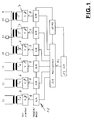
- FIG. 1 There are designated I1, I2, I3 or U1, U2, U3 current transformers or voltage transformers. Their outputs 4, 5 are with the inputs 6, 7 of Adaptation amplifier 8 connected, the outputs of which are led to sample-hold units, in which the determined value of the input variables is recorded and buffered.
- the sample-hold units are connected to a multiplexer 11, the output 12 of which is led to an A / D converter.
- a / D converter 13, multiplexer 11 and sample hold units 10 are controlled by a ⁇ processor 14.
Abstract
Description
Die Neuerung/Erfindung betrifft eine elektrische Anordnung zur Erfassung von Meßgrößen wie Wirkleistung, Blindleistung, Wirkfaktor und Blindfaktor mit den weiteren Merkmalen des Oberbegriffes des Patentanspruchs 1.The innovation / invention relates to an electrical arrangement for recording measured variables such as active power, reactive power, active factor and reactive factor with the further features of the preamble of
Um in einem Einphasen- bzw. Mehrphasensystem elektrische Meßgrößen wie Wirkleistung, Blindleistung, Wirkfaktor und Blindfaktor nach DIN 40110 zu messen, werden Spannungs- und Stromwandler sekundärseitig sternförmig zusammengeschaltet und digital abgetastet. Dabei ist die Wirkleistung definiert als
![]()
![]()
Mit Anpassungsverstärkern werden die Momentanwerte aller Eingangsgrößen erfaßt und für die Dauer der seriell erfolgenden A/D-Wandlung kurzzeitig analog gespeichert. Die Spannungs- und Stromvektoren der Wechselstromnetze werden jedoch mit einem Phasenfehler der Wandler auf der Sekundärseite abgebildet.In order to measure electrical measurands such as active power, reactive power, active factor and reactive factor in accordance with DIN 40110 in a single-phase or multi-phase system, voltage and current transformers are connected together in a star configuration on the secondary side and digitally sampled. The active power is defined as
![]()
![]()
The instantaneous values of all input variables are recorded with adaptation amplifiers and briefly stored in analog form for the duration of the serial A / D conversion. However, the voltage and current vectors of the AC networks are mapped with a phase error in the converter on the secondary side.
Zwar ist es bei Geräten nach dem Stand der Technik auch bereits möglich, durch komplizierte Korrekturschaltungen mit einer Reihe von zusätzlichen Bauteilen und aufwendigen Abgleichschritten in der Gerätefertigung eine Kompensation der Phasenfehler zu erreichen. Trotz des Aufwandes ergibt sich dabei aber ein frequenzabhängiger Meßfehler, der nur einen eingeschränkten Frequenzarbeitsbereich der Geräte nach dem Stand der Technik zu läßt.In the case of devices according to the state of the art, it is already possible to compensate for the phase errors by means of complicated correction circuits with a number of additional components and complex adjustment steps in the device manufacture. Despite the effort, however, there is a frequency-dependent measurement error which only allows a limited frequency working range of the devices according to the prior art.
Der Erfindung liegt die Aufgabe zugrunde, eine Vorrichtung mit den Merkmalen des Oberbegriffes des Anspruches 1 derart weiterzubilden, daß Phasenfehler ausgeglichen werden können.The invention has for its object to develop a device with the features of the preamble of
Die Aufgabe wird durch die weiteren Merkmale des Anspruches 1 gelöst. Eine vorteilhafte Weiterbildung der Anordung ergibt sich aus Anspruch 2. Ein Meßverfahren ist Gegenstand der Ansprüche 3 - 5.The object is achieved by the further features of
Bei einem digitalen System kann der auftretende Phasenfehler auf einfache Weise dadurch korrigiert werden, daß bei einer bestimmten Frequenz die Abtastzeitpunkte t1, t2 ... um einen gewissen Fehlbetrag tFx zeitlich verschoben werden. Nach dieser Korrektur lassen sich die Werte miteinander verknüpfen, die mit einer synchronen Abtastung zeitlich korreliert sind.In a digital system of occurring phase errors can be corrected by a simple way, that at a certain frequency, the sampling instants t1, t2 ... to t a certain loss Fx are shifted in time. After this correction, the values that are temporally correlated with a synchronous sampling can be linked.
Die Erfindung ist anhand von zwei Zeichnungsfiguren näher erläutert. Diese zeigen:
- Fig. 1
- ein Prinzipschaltbild zur Erläuterung der Struktur der digitalen Meßdatenverarbeitungsanordnung,
- Fig. 2
- Spannungs/Zeitdiagramme zur Erläuterung der zeitlichen Verschiebung der Abtastzeitpunkte t1, t2 ... nach der Erfindung.
- Fig. 1
- 1 shows a basic circuit diagram to explain the structure of the digital measurement data processing arrangement,
- Fig. 2
- Voltage / time diagrams for explaining the time shift of the sampling times t1, t2 ... according to the invention.
Zunächst wird auf Fig. 1 Bezug genommen. Dort sind mit I₁, I₂, I₃ bzw. U₁, U₂, U₃ Stromwandler bzw. Spannungswandler bezeichnet. Deren Ausgänge 4, 5 sind mit den Eingängen 6, 7 von Anpassungsverstärker 8 verbunden, deren Ausgänge zu Sample-Hold-Einheiten geführt sind, in denen der ermittelte Wert der Eingangsgrößen erfaßt und zwischengespeichert wird. Die Sample-Hold-Einheiten sind mit einem Multiplexer 11 verschaltet, dessen Ausgang 12 zu einem A/D-Wandler geführt ist. A/D-Wandler 13, Multiplexer 11 und Sample-Hold-Einheiten 10 werden durch einen µ-Prozessor 14 gesteuert.First, reference is made to FIG. 1. There are designated I₁, I₂, I₃ or U₁, U₂, U₃ current transformers or voltage transformers. Their outputs 4, 5 are with the
Aus Zeichnungsfig. 2 ergibt sich der Betrag der zeitlichen Verschiebung tFU₂ bzw tFU₃, die sich gegenüber der Phasenlage der Spannung U₁ (t) ergibt.From drawing fig. 2 gives the amount of time shift t F U₂ or t F U₃, which results in relation to the phase of the voltage U₁ (t).
Analog werden für I₁ (t), I₂ (t) und I₃ (t) Phasenverschiebungen tFx in bezug auf U₁ von t vorgenommen. Durch derartige Verschiebungen ergeben sich phasenrichtige Strom-Spannungsvektoren auf der Sekundärseite der Wandlermeßeinrichtung.Similarly, for I₁ (t), I₂ (t) and I₃ (t) phase shifts t Fx with respect to U₁ of t are made. Such shifts result in in-phase current-voltage vectors on the secondary side of the converter measuring device.
- 44th
- Ausgangexit
- 55
- Ausgangexit
- 66
- Eingangentrance
- 77
- Eingangentrance
- 88th
- AnpassungsverstärkerAdaptation amplifier
- 1010th
- Sample-Hold-EinheitenSample hold units
- 1111
- Multiplexermultiplexer
- 1212th
- Ausgang zu einem A/D-WandlerOutput to an A / D converter
- 1313
- A/D-WandlerA / D converter
- 1414
- µ-Prozessorµ processor
Claims (5)
gekennzeichnet durch
folgende Merkmale:
marked by
following features:
gekennzeichnet durch
eine Einrichtung zur Erfassung der Zeitdauer der Grundschwingungsperiode einer Meßgröße und zur Vornahme einer frequenzunabhängigen Durchführung der Phasenkorrektur mittels einer Korrektur des Fehlbetrages tFx.Electronic arrangement according to claim 1,
marked by
a device for recording the duration of the fundamental period of a measured variable and for carrying out the frequency correction independently of the frequency by means of a correction of the shortfall t Fx .
gekennzeichnet durch
folgende Verfahrensschritte:
marked by
following process steps:
dadurch gekennzeichnet,
daß die Meßzeitpunktverschiebung für jeden Wandler abgespeichert wird, um sie bei einer sich zyklisch wiederholenden Meßwertabtastung ohne Phasenfehler verwenden zu können.Method according to claim 3,
characterized,
that the measurement time offset is stored for each transducer so that it can be used in a cyclically repeating measurement value sampling without phase errors.
gekennzeichnet durch
Heranziehung der abgespeicherten Meßzeitpunktverschiebung auch für andere Eingangsbedingungen wie veränderte Netzfrequenz und Leerlaufstrom I₀ der Meßwandler, (wobei I₀ = Magnetisierungsstrom Iµ + Eisenverluststrom IFe).Method according to claim 4,
marked by
Use of the stored measurement time shift also for other input conditions such as changed mains frequency and idle current I₀ of the transducers (where I₀ = magnetizing current I µ + iron leakage current I Fe ).
Applications Claiming Priority (2)
| Application Number | Priority Date | Filing Date | Title |
|---|---|---|---|
| DE9213457U DE9213457U1 (en) | 1992-10-08 | 1992-10-08 | |
| DE9213457U | 1992-10-08 |
Publications (1)
| Publication Number | Publication Date |
|---|---|
| EP0591942A1 true EP0591942A1 (en) | 1994-04-13 |
Family
ID=6884517
Family Applications (1)
| Application Number | Title | Priority Date | Filing Date |
|---|---|---|---|
| EP93116159A Withdrawn EP0591942A1 (en) | 1992-10-08 | 1993-10-06 | Electronic device for measuring such variables as active and reactive power and power factor |
Country Status (2)
| Country | Link |
|---|---|
| EP (1) | EP0591942A1 (en) |
| DE (1) | DE9213457U1 (en) |
Cited By (5)
| Publication number | Priority date | Publication date | Assignee | Title |
|---|---|---|---|---|
| DE19738140A1 (en) * | 1997-09-01 | 1999-03-11 | Siemens Ag | Measuring arrangement for power and / or power factor measurement at at least one measuring point in an AC voltage network |
| WO2004017079A2 (en) * | 2002-08-19 | 2004-02-26 | Tdk Semiconductor Corporation | Method and apparatus for obtaining power computation parameters |
| WO2009007237A1 (en) * | 2007-07-06 | 2009-01-15 | Siemens Aktiengesellschaft | Method and apparatus for correcting the phase error in measurement-control equipment for a power network |
| CN105607022A (en) * | 2015-12-18 | 2016-05-25 | 大豪信息技术(威海)有限公司 | Phase frequency calibration method and system for instrument with function of power measurement |
| CN113330678A (en) * | 2019-07-02 | 2021-08-31 | 东芝三菱电机产业系统株式会社 | Power conversion device and power conversion system |
Families Citing this family (3)
| Publication number | Priority date | Publication date | Assignee | Title |
|---|---|---|---|---|
| DE4329103B4 (en) * | 1993-08-30 | 2004-06-24 | Aeg Energietechnik Gmbh | Method for state determination of electrical energy transmission networks |
| DE19513534A1 (en) * | 1995-04-10 | 1996-10-17 | Stepper & Co | Measuring electrical power consumption for single or multi-phase AC supplies |
| DE19532588C1 (en) * | 1995-09-04 | 1997-03-06 | Siemens Ag | Electricity meter |
Citations (3)
| Publication number | Priority date | Publication date | Assignee | Title |
|---|---|---|---|---|
| DE3611680A1 (en) * | 1986-04-08 | 1987-10-15 | Bbc Brown Boveri & Cie | Method for measurement conversion |
| EP0377282A1 (en) * | 1988-12-02 | 1990-07-11 | General Electric Company | Electronic meter digital phase compensation |
| EP0466453A2 (en) * | 1990-07-10 | 1992-01-15 | Polymeters Response International Limited | Improvements in and relating to electricity meters using current transformers |
-
1992
- 1992-10-08 DE DE9213457U patent/DE9213457U1/de not_active Expired - Lifetime
-
1993
- 1993-10-06 EP EP93116159A patent/EP0591942A1/en not_active Withdrawn
Patent Citations (3)
| Publication number | Priority date | Publication date | Assignee | Title |
|---|---|---|---|---|
| DE3611680A1 (en) * | 1986-04-08 | 1987-10-15 | Bbc Brown Boveri & Cie | Method for measurement conversion |
| EP0377282A1 (en) * | 1988-12-02 | 1990-07-11 | General Electric Company | Electronic meter digital phase compensation |
| EP0466453A2 (en) * | 1990-07-10 | 1992-01-15 | Polymeters Response International Limited | Improvements in and relating to electricity meters using current transformers |
Cited By (11)
| Publication number | Priority date | Publication date | Assignee | Title |
|---|---|---|---|---|
| DE19738140A1 (en) * | 1997-09-01 | 1999-03-11 | Siemens Ag | Measuring arrangement for power and / or power factor measurement at at least one measuring point in an AC voltage network |
| US6459257B1 (en) | 1997-09-01 | 2002-10-01 | Siemens Aktiengesellschaft | Measuring system for measuring power and/or power factors at at least one measuring point in an a.c. voltage network |
| WO2004017079A2 (en) * | 2002-08-19 | 2004-02-26 | Tdk Semiconductor Corporation | Method and apparatus for obtaining power computation parameters |
| WO2004017079A3 (en) * | 2002-08-19 | 2004-04-29 | Tdk Semiconductor Corp | Method and apparatus for obtaining power computation parameters |
| US6943714B2 (en) | 2002-08-19 | 2005-09-13 | Tdk Semiconductor Corporation | Method and apparatus of obtaining power computation parameters |
| US7102556B2 (en) | 2002-08-19 | 2006-09-05 | Tdk Semiconductor,Corp. | Method and apparatus for obtaining power computation parameters |
| WO2009007237A1 (en) * | 2007-07-06 | 2009-01-15 | Siemens Aktiengesellschaft | Method and apparatus for correcting the phase error in measurement-control equipment for a power network |
| CN101339210B (en) * | 2007-07-06 | 2011-07-06 | 西门子电力自动化有限公司 | Method and device for correcting phase error of electric network measuring and controlling equipment |
| CN105607022A (en) * | 2015-12-18 | 2016-05-25 | 大豪信息技术(威海)有限公司 | Phase frequency calibration method and system for instrument with function of power measurement |
| CN113330678A (en) * | 2019-07-02 | 2021-08-31 | 东芝三菱电机产业系统株式会社 | Power conversion device and power conversion system |
| CN113330678B (en) * | 2019-07-02 | 2023-11-24 | 东芝三菱电机产业系统株式会社 | Power conversion device and power conversion system |
Also Published As
| Publication number | Publication date |
|---|---|
| DE9213457U1 (en) | 1993-01-28 |
Similar Documents
| Publication | Publication Date | Title |
|---|---|---|
| AU618843B2 (en) | Equipment for and methods of locating the position of a fault on a power transmission line | |
| CH650339A5 (en) | INTRINSICALLY SAFE, DIGITAL TESTING DEVICE AND METHOD FOR OPERATING THE DEVICE. | |
| EP0901019A2 (en) | Electricity meter for measuring physical variables, which are parameters or functions of the voltages and/or currents measured by the electricity meter | |
| CH663283A5 (en) | MEASURING ARRANGEMENT FOR CHANGING OR THREE-PHASE NETWORKS. | |
| EP0591942A1 (en) | Electronic device for measuring such variables as active and reactive power and power factor | |
| DE3620484C2 (en) | ||
| DE19639410A1 (en) | Measuring device for electrical power | |
| DE69730545T2 (en) | Arithmetic unit | |
| DE3917020C2 (en) | ||
| EP0577653B1 (en) | Process for finding the transmission properties of an electric line | |
| DE4330179C2 (en) | Digital method for determining a measured variable from an electrical signal | |
| DE2814125C2 (en) | Device for non-destructive testing of materials | |
| DE10028593C1 (en) | Digital/analogue signal conversion method uses transformation with orthogonal functions and determination of coefficients for re-conversion into analogue range | |
| EP0767917B1 (en) | Digital process for determining the effective value of a periodic electric measurement signal | |
| DE19613732B4 (en) | Method for generating a measurement signal proportional to an electrical reactive power | |
| DE4221057A1 (en) | Method of recording electrical energy consumption | |
| EP0367860A1 (en) | Amplitude measuring process of a periodic electrical signal G(t) in a band of signals U(t) | |
| DE2715283C2 (en) | Electronic three-phase meter | |
| DE19513534A1 (en) | Measuring electrical power consumption for single or multi-phase AC supplies | |
| DE2710712A1 (en) | Measurement electrical power and energy - with sensing time error compensation using intermediate storage and interpolation | |
| DE3235741A1 (en) | DIGITAL-ANALOG CONVERTER WITH POTENTIAL SEPARATION | |
| DE2852802C2 (en) | ||
| DD148539B1 (en) | METHOD AND CIRCUIT ARRANGEMENT FOR THE DIGITAL MEASUREMENT OF ELECTRICAL SIZES | |
| AT393742B (en) | Digital AC voltage root mean square value meter | |
| DE2646630A1 (en) | Measurement of AC power of transient processes - uses multiplication of signals representing instantaneous values of voltage and current |
Legal Events
| Date | Code | Title | Description |
|---|---|---|---|
| PUAI | Public reference made under article 153(3) epc to a published international application that has entered the european phase |
Free format text: ORIGINAL CODE: 0009012 |
|
| AK | Designated contracting states |
Kind code of ref document: A1 Designated state(s): CH DE ES FR GB IT LI SE |
|
| 17P | Request for examination filed |
Effective date: 19940830 |
|
| 17Q | First examination report despatched |
Effective date: 19970514 |
|
| STAA | Information on the status of an ep patent application or granted ep patent |
Free format text: STATUS: THE APPLICATION IS DEEMED TO BE WITHDRAWN |
|
| 18D | Application deemed to be withdrawn |
Effective date: 20001011 |