EP0591037B1 - Method for obtaining and treating data for monitoring the movement of fluids in a reservoir - Google Patents
Method for obtaining and treating data for monitoring the movement of fluids in a reservoir Download PDFInfo
- Publication number
- EP0591037B1 EP0591037B1 EP93402355A EP93402355A EP0591037B1 EP 0591037 B1 EP0591037 B1 EP 0591037B1 EP 93402355 A EP93402355 A EP 93402355A EP 93402355 A EP93402355 A EP 93402355A EP 0591037 B1 EP0591037 B1 EP 0591037B1
- Authority
- EP
- European Patent Office
- Prior art keywords
- waves
- seismic
- borehole
- reservoir
- sub
- Prior art date
- Legal status (The legal status is an assumption and is not a legal conclusion. Google has not performed a legal analysis and makes no representation as to the accuracy of the status listed.)
- Expired - Lifetime
Links
Images


Classifications
-
- G—PHYSICS
- G01—MEASURING; TESTING
- G01V—GEOPHYSICS; GRAVITATIONAL MEASUREMENTS; DETECTING MASSES OR OBJECTS; TAGS
- G01V1/00—Seismology; Seismic or acoustic prospecting or detecting
- G01V1/40—Seismology; Seismic or acoustic prospecting or detecting specially adapted for well-logging
- G01V1/42—Seismology; Seismic or acoustic prospecting or detecting specially adapted for well-logging using generators in one well and receivers elsewhere or vice versa
-
- G—PHYSICS
- G01—MEASURING; TESTING
- G01V—GEOPHYSICS; GRAVITATIONAL MEASUREMENTS; DETECTING MASSES OR OBJECTS; TAGS
- G01V1/00—Seismology; Seismic or acoustic prospecting or detecting
- G01V1/16—Receiving elements for seismic signals; Arrangements or adaptations of receiving elements
- G01V1/20—Arrangements of receiving elements, e.g. geophone pattern
Definitions
- the present invention relates to a method of acquisition and processing of seismic data, used in the context of a repetitive monitoring of the movement of the fluids impregnating a reservoir located deep in the basement below a surface alteration zone .
- the invention finds a particularly advantageous application in the field of applied geophysics where it is sought in particular to collect information on the movements of hydrocarbons and water in an underground reservoir by repeated reflection seismic methods.
- seismic reflection makes it possible to reconstruct deformations of the subsoil from the measurement of the propagation times of the seismic waves emitted up to the main interfaces.
- the signal-to-noise ratio of the recordings is good, it is possible to measure the reflectivity of these interfaces, which is proportional to the amplitude of the reflected seismic waves. Therefore, it is possible to follow variations in lithology or porosity of the subsoil, and therefore to describe for example more precisely the nature of underground hydrocarbon tanks.
- a technical solution to the aforementioned problems of simple reflection seismic is repetitive monitoring, that is to say a method of recording seismic reflection repeated at intervals of time sufficient for the movement of fluids in the tank to produce differences. detectable propagation time or amplitude of the reflected waves, between the successive reflection seismic profiles. By comparing two recordings, a relative measurement of the reflected seismic waves is carried out, the sensitivity of which is much higher than that of a single acquisition in the case of simple reflection seismic, since it makes it possible to identify displacements of the fluids without them these are detected directly.
- all these above-mentioned seismic reflection acquisition methods aim to obtain a continuous image of the subsoil (on a surface, a line or near a well) and all use a method of addition on the cover. multiple to improve the signal to noise ratio of the recordings obtained.
- Well seismic methods provide recordings whose resolution and signal-to-noise ratio are generally adapted to repetitive monitoring, but the realization of these methods is difficult because of the limited accessibility of wells and their investigation remains punctual around only existing wells.
- the present invention provides a new method of acquisition and processing of seismic data, suitable for repetitive monitoring by seismic reflection of fluids in an underground reservoir, which aims to overcome the drawbacks of the above-mentioned prior seismic methods.
- a 0-phase trace a trace made up of reflections whose maximum or minimum amplitudes are located vertically (in propagation time) of the reflective interfaces of the subsoil and whose values are proportional to the reflectivity of these interfaces.
- a zero offset trace is a trace equivalent to that which would have been recorded using a transmitter and a receiver placed in the same place, which corresponds to a propagation of the waves along the vertical.
- the term “low coverage trace” is understood to mean a trace formed by the addition of a reduced number of traces.
- a measurement corresponds to one or more seismic emissions recorded separately by each of the receivers arranged vertically in the hole, placed in this point, which extends under the surface alteration zone of the basement.
- the holes are arranged according to a grid of more or less spaced points so as to sample the reservoir in a representative manner. It will be noted in this case that the investigation is not linked to the presence and availability of deep holes.
- the aim of the method according to the invention is not to reconstruct a continuous image of the basement on a given date but to obtain at each point of the grid a 0-phase trace with zero offset of low coverage, it that is to say a recording of the waves reflected vertically from the hole positioned at each point.
- This non-migrated trace is representative of the average reflectivity of the interfaces on the surface illuminated by the reflected waves, this illuminated surface being called the Fresnel zone.
- the emission of seismic waves in the basement is repeated on different dates and the 0-phase traces with low offset zero offset are compared obtained from the emissions carried out at the different dates, by correcting variations in propagation time linked to seasonal changes in the surface alteration zone on said traces, and by calculating differences in amplitude and propagation time at the level of the corresponding reflections on said traces in the sub- soil in order to obtain information on the movement of fluids in the reservoir to be studied.
- the holes made make it possible to keep the receivers buried, available and accessible for each emission, even if the emission dates are spaced several months or several years apart.
- the method according to the invention does not require the repositioning or the immobilization of numerous receivers, as is the case for seismic methods from the surface.
- the method according to the invention makes it possible to obtain a spatial and temporal sampling of the reservoir at intervals determined by the complexity of the reservoir, the speed of movement of the fluids and the budget available.
- the proposed method which involves making shallow holes fitted with receivers, has a lower cost than the repetition of continuous profiles required by the surface sisimics of the prior art.
- the use of buried receivers and arranged vertically makes it possible to obtain seismic traces having both a high signal to noise ratio and good vertical resolution, in particular thanks to the vertical filtering of the effects of surface and positioning of the device under the surface alteration zone of the basement.
- the processing of seismic acquisitions comprises a step of level by level deconvolution of the waves reflected by a direct wave, making it possible to obtain reflections whose amplitude is representative of the reflectivity of the sub- ground vertical to the hole.
- This advantageous and original stage of treatment runs counter to all the assumptions of those skilled in the art. Indeed, because the receivers are shallow, the reflected waves travel a much longer path than direct waves, and the skilled person can think a priori that the operation of deconvolution of one by the other will not give a satisfactory result. In fact, the result of the deconvolution is satisfactory because the direct and reflected waves are essentially shaped by their passage through the surface alteration zone.
- FIG. 1 an example of a portion of land is shown, with a partial view of the basement.
- a surface alteration zone 2 which extends in depth over approximately 70 meters and a reservoir 1 located approximately 1200 meters deep , containing fluids not shown in this figure, such as for example water and gas.
- This reservoir 1 seen in section, extends over the entire length of the portion of land shown.
- the implementation of a recording is distinguished from the method of acquisition and processing of seismic data according to the invention, aiming in particular to follow the displacements of the fluids in the reservoir 1.
- each point A there is provided at each point A with a predetermined grid on the surface, a hole 100 of vertical axis UU 'and of shallow depth in the basement above the reservoir 1.
- the points A of the grid are more or less spaced from each other, here for example from 250 to 500 meters, so as to correctly sample the reservoir 1.
- the grid has about twenty points A.
- Each hole 100 of the grid extends from the surface to a depth here of about 150 meters, inside an environment in which seismic waves propagate preferably at constant speed and which is located under the surface alteration zone 2.
- holes 100 are made with the conventional drills used for the preparation of VT core samples, necess areas to measure the propagation times in the superficial levels.
- Each hole 100 has a diameter of about 10 centimeters.
- each hole 100 is positioned along its vertical axis U-U 'at least six to eight receivers 101,102,103,104,105,106,107,108, which are connected separately to the surface. These receivers are distant in the hole from two to ten meters approximately depending on the speed of the waves emitted in the environment surrounding the receivers and the frequency of the waves emitted. The receivers are lowered and cemented directly in each hole 100, so that they are fixed in said hole. Each receiver is provided with a box reinforcing its tightness and is connected to the surface to one or more waterproof sockets located under a manhole 110 placed on the surface.
- the receivers of the hole in question are then connected separately to a recorder 300 which is connected to the waterproof socket (s) located under the manhole 110.
- the receivers used are for example geophones or triphones.
- the triphones can consist of three separate mini-sensors, arranged in a plastic tube. Their orientation in the hole can be determined relative to the direction of a transmission carried out at the surface with a certain offset.
- seismic waves are emitted in the subsoil by means of an emitting source 200 placed on the surface near to the vertical UU 'of each hole 100.
- the emitting source 200 is placed about 20 meters from the vertical of the hole in question.
- several transmissions are made at each recording, either on site to improve the signal to noise ratio of the recordings, or by gradually shifting so as to obtain a collection of traces around the vertical UU 'of the hole 100.
- the low The depth of the receptors can limit the effectiveness of the proposed treatment to offsets not exceeding the average depth of these receptors, in this case around 100 meters on either side of the hole 100.
- each emission is at the origin on each of the receivers of the hole 100 recorded separately, of a direct arrival of direct incident wave or downward wave 10, and of arrivals of waves reflected at the interfaces of the basement, formed in particular by the fluids of the reservoir 1, or rising waves 20.
- the waves are recorded and transmitted to the recorder 300.
- each emission or group of emissions on each hole provides one or more seismic recordings on a given date which will make it possible to measure the reflectivity of the subsoil vertically from each hole.
- the record or records obtained on a given date are transformed for each hole according to the processing steps of the method according to the invention. It should be noted that in the context of repetitive monitoring, the dates for taking seismic measurements or recordings can be spaced several months or even several years apart.
- the first arrivals of the direct incident waves 10 are pointed so as to measure the propagation time of these waves, to the various receivers. These delays are then used in two ways: they are added to the arrival times of the various reflected waves 20, which has the effect of horizontalizing them; they are used to identify and correct seasonal variations in speed in the surface alteration zone.
- the rising (reflected) waves 20 and the falling (direct) waves 10 are then separated by filtering in frequency and in number of waves knowing that said rising and falling waves do not have the same apparent speed.
- the receiver or receiver deconvolves the rising or reflected waves 20 by the falling or direct wave 10 arriving at the receiver in question in order to obtain for each receiver a 0-phase trace 30, as shown in FIG. 4.
- FIG. 6 shows the correspondence between this 0-phase trace with zero offset 40, and the reflectivity R 1 , R 2 of the deep interfaces of the subsoil around the hole 100 considered.
- the method of acquisition and processing of seismic data allows, on the one hand, on a given date to obtain a sampling of the reflectivity of basement according to the grid shown in Figure 1.
- it allows by repeating on dates spaced in time J 1 and J 2 the seismic emissions near the different holes 100 of the grid, and comparing for each hole the different 0-phase traces with zero offset obtained at the end of the treatment, to obtain an evaluation of the variations in saturation of the fluids in the reservoir 1 distributed in a discrete manner.
- the reservoir 1 comprises two fluids 1a, 1b, such as gas and water separated by a gradual transition, which between dates D 1 and D 2 will move towards the top as a result of gas production.
- the reservoir I On date J 1 and on a vertical U-U ', the reservoir I has a hydrocarbon saturation of approximately 60%, and a water saturation of 40%, while subsequently, on date D 2 , the reservoir I has, along the same vertical line, reversed hydrocarbon / water saturations as a result of the rise in the transition zone.
- Each point of the grid would then correspond to a vertical flute comprising several hydrophones or groups of hydrophones, immersed above the bottom and connected to an autonomous recorder located in a sealed sphere.
- the transmissions are made directly above the flute from a seismic vessel which collects the plotter and recorder unit after each acquisition.
Description
La présente invention concerne une méthode d'acquisition et de traitement de données sismiques, utilisée dans le cadre d'une surveillance répétitive du déplacement des fluides imprégnant un réservoir situé en profondeur dans le sous-sol en dessous d'une zone d'altération superficielle.The present invention relates to a method of acquisition and processing of seismic data, used in the context of a repetitive monitoring of the movement of the fluids impregnating a reservoir located deep in the basement below a surface alteration zone .
L'invention trouve une application particulièrement avantageuse dans le domaine de la géophysique appliquée où l'on recherche notamment à recueillir des informations sur les déplacements des hydrocarbures et de l'eau dans un réservoir souterrain par des méthodes de sismique réflexion répétée.The invention finds a particularly advantageous application in the field of applied geophysics where it is sought in particular to collect information on the movements of hydrocarbons and water in an underground reservoir by repeated reflection seismic methods.
En effet, la sismique réflexion permet de reconstituer des déformations du sous-sol à partir de la mesure des temps de propagation des ondes sismiques émises jusqu'aux principales interfaces. En outre, lorsque le rapport signal sur bruit des enregistrements est bon, il est possible de mesurer la réflectivité de ces interfaces, qui est proportionnelle à l'amplitude des ondes sismiques réfléchies. De ce fait, il est possible de suivre des variations de lithologie ou de porosité du sous-sol, et donc de décrire par exemple de manière plus précise la nature des réservoirs souterrains à hydrocarbures.Indeed, seismic reflection makes it possible to reconstruct deformations of the subsoil from the measurement of the propagation times of the seismic waves emitted up to the main interfaces. In addition, when the signal-to-noise ratio of the recordings is good, it is possible to measure the reflectivity of these interfaces, which is proportional to the amplitude of the reflected seismic waves. Therefore, it is possible to follow variations in lithology or porosity of the subsoil, and therefore to describe for example more precisely the nature of underground hydrocarbon tanks.
En ce qui concerne la détection des fluides dans un tel réservoir, il arrive que dans des conditions favorables, c'est-à-dire un réservoir meuble et poreux contenant du gaz ou de l'huile à faible viscosité, l'on repère sur un profil de sismique réflexion la présence de fluides ou la position de leurs interfaces, à l'origine d'anomalies d'amplitude ou de changement de configuration des réflexions sismiques. Mais, dans la plupart des cas, cette détection directe des fluides n'est pas possible à cause des faibles variations de réflectivité induites par le déplacement des fluides ou à cause d'un manque de résolution de la méthode employée.With regard to the detection of fluids in such a tank, it sometimes happens that under favorable conditions, that is to say a loose and porous tank containing gas or oil with low viscosity, we find on a seismic profile reflecting the presence of fluids or the position of their interfaces, causing amplitude anomalies or a change in configuration of seismic reflections. However, in most cases, this direct detection of fluids is not possible because of the small variations in reflectivity induced by the displacement of the fluids or because of a lack of resolution of the method used.
Une solution technique aux problèmes précités de la sismique réflexion simple est la surveillance répétitive, c'est-à-dire un procédé d'enregistrement de sismique réflexion répété à des intervalles de temps suffisants pour que le déplacement des fluides dans le réservoir produise des différences détectables de temps de propagation ou d'amplitude des ondes réfléchies, entre les profils de sismique réflexion successifs. En comparant deux enregistrement, on réalise une mesure relative des ondes sismiques réfléchies, dont la sensibilité est bien supérieure à celle d'une acquisition unique dans le cas de la sismique réflexion simple, car elle permet de repérer des déplacements des fluides sans que ceux-ci soient détectés directement.A technical solution to the aforementioned problems of simple reflection seismic is repetitive monitoring, that is to say a method of recording seismic reflection repeated at intervals of time sufficient for the movement of fluids in the tank to produce differences. detectable propagation time or amplitude of the reflected waves, between the successive reflection seismic profiles. By comparing two recordings, a relative measurement of the reflected seismic waves is carried out, the sensitivity of which is much higher than that of a single acquisition in the case of simple reflection seismic, since it makes it possible to identify displacements of the fluids without them these are detected directly.
Il convient cependant de préciser que la surveillance répétitive nécessite, quelle que soit la méthode employée pour obtenir les enregistrements de sismique réflexion, une utilisation répétée des dispositifs de mise en oeuvre, repositionnés de manière stricte, et des enregistrements présentant un rapport signal sur bruit élevé et une bonne résolution verticale.It should however be specified that repetitive monitoring requires, whatever the method used to obtain the reflection seismic recordings, repeated use of the implementation devices, strictly repositioned, and recordings with a high signal-to-noise ratio and good vertical resolution.
Actuellement, les méthodes de sismique réflexion connues (US-A-2 900 037, GB-A-2 153 529) et mises en oeuvre dans le cadre d'une surveillance répétitive, sont des méthodes sismiques à partir de la surface en 2D ou 3D, ou puits-à-puits ou bien mixte surface-puits comme les P. S. V (Profil de Sismique Vertical). A titre de document de référence sur les méthodes de géophysique employées pour effectuer la surveillance répétitive des fluides, on peut consulter le document "New Dimensions in Geophysics for Resevoir Monitoring, SPE formation Evaluation", Juin 1991, p. 141-150 (R.J. Greaves, W.B. Beydoun et B.R. Spies).Currently, known seismic reflection methods (US-A-2,900,037, GB-A-2,153,529) and implemented in the context of repetitive monitoring, are seismic methods from the surface in 2D or 3D, or well-to-well or mixed surface-well as the PS V (Vertical Seismic Profile). As a reference document on the geophysical methods used to carry out repetitive monitoring of fluids, one can consult the document "New Dimensions in Geophysics for Resevoir Monitoring, SPE formation Evaluation", June 1991, p. 141-150 (R.J. Greaves, W.B. Beydoun and B.R. Spies).
D'une manière générale, toutes ces méthodes d'acquisition de sismique réflexion précitées visent à obtenir une image continue du sous-sol (sur une surface, une ligne ou près d'un puits) et utilisent toutes un procédé d'addition en couverture multiple pour améliorer le rapport signal sur bruit des enregistrements obtenus.In general, all these above-mentioned seismic reflection acquisition methods aim to obtain a continuous image of the subsoil (on a surface, a line or near a well) and all use a method of addition on the cover. multiple to improve the signal to noise ratio of the recordings obtained.
Dans le cadre de la surveillance répétitive, aucune de ces méthodes précitées bien connues de l'homme du métier ne sont satisfaisantes car elles se heurtent, en terrestre, à des problèmes d'accessibilité et de variation saisonnière des propriétés des niveaux superficiels du sous-sol, et en marine, aux difficultés de repositionnement exact des passages successifs.In the context of repetitive monitoring, none of these aforementioned methods well known to those skilled in the art are satisfactory because they come up against problems of accessibility and seasonal variation in the properties of the surface levels of the sub-surface. ground, and in marine, with the difficulties of exact repositioning of the successive passages.
A terre, la réalisation de sismique réflexion à partir de la surface en 2D ou en 3D est souvent difficile car elle nécessite la mise en place d'un grand nombre de récepteurs sur une surface étendue, ce qui pose des problèmes d'accessibilité sur le terrain (viabilité, permittage) et d'immobilisation ou de repositionnement d'un dispositif d'acquisition important. De plus, les enregistrements obtenus à l'aide d'une sismique de surface présentent un rapport signal sur bruit moyen car le bruit sismique est important en surface. Ce bruit sismique en surface est une onde de sol et une onde aérienne. D'autre part la résolution de ces enregistrements est faible car il y a une absorption de hautes fréquences dans la zone d'altération superficielle du sous-sol à étudier, et un filtrage lié aux interférences entre les récepteurs disposés sur le sol. En outre, le coût de mise en oeuvre de la sismique de surface est relativement élevé.On land, carrying out seismic reflection from the surface in 2D or 3D is often difficult because it requires the installation of a large number of receivers over a large area, which poses accessibility problems on the land (viability, permittage) and immobilization or repositioning of an important acquisition device. In addition, the recordings obtained using surface seismic have an average signal-to-noise ratio because the seismic noise is significant at the surface. This seismic noise on the surface is a ground wave and an aerial wave. On the other hand, the resolution of these recordings is low because there is an absorption of high frequencies in the surface alteration zone of the basement to be studied, and filtering linked to interference between the receivers placed on the ground. In addition, the cost of implementing surface seismic is relatively high.
Les méthodes de sismique de puits fournissent des enregistrements dont la résolution et le rapport signal sur bruit sont en général adaptés à la surveillance répétitive, mais la réalisation de ces méthodes est difficile à cause de l'accessibilité limitée des puits et leur investigation reste ponctuelle autour des seuls puits existants.Well seismic methods provide recordings whose resolution and signal-to-noise ratio are generally adapted to repetitive monitoring, but the realization of these methods is difficult because of the limited accessibility of wells and their investigation remains punctual around only existing wells.
La présente invention propose une nouvelle méthode d'acquisition et de traitement de données sismiques, adaptée à la surveillance répétitive par sismique réflexion des fluides dans un réservoir souterrain, qui vise à pallier les inconvénients des méthodes sismiques antérieures précitées.The present invention provides a new method of acquisition and processing of seismic data, suitable for repetitive monitoring by seismic reflection of fluids in an underground reservoir, which aims to overcome the drawbacks of the above-mentioned prior seismic methods.
Plus particulièrement, selon l'invention, cette méthode comporte les étapes suivantes consistant à :
- a) aménager en chaque point d'une grille prédéterminée en surface, un trou d'axe vertical de faible profondeur dans le sous-sol au-dessus du réservoir, et traversant la zone d'altération superficielle,
- b) positionner dans chaque trou suivant son axe vertical une pluralité de récepteurs fixes et destinés à être connectés séparément à un enregistreur placé en surface,
- c) émettre à proximité de chaque trou des ondes sismiques dans le sous-sol au moyen d'une source émettrice placée en surface à proximité de la verticale de ce trou,
- d) enregistrer pour chaque trou, au moyen des récepteurs placés dans ledit trou, les ondes sismiques incidentes directes et les ondes sismiques réfléchies aux interfaces des couches profondes du sous-sol, chaque récepteur fournissant un enregistrement séparé d'une onde incidente et de plusieurs ondes réfléchies,
- e) pour chaque trou, effectuer le traitement suivant :
- pointer la première arrivée des ondes incidentes directes,
- horizontaliser les ondes réfléchies,
- séparer les ondes réfléchies et les ondes incidentes directes,
- déconvoluer récepteur par récepteur les ondes réféchies par l'onde incidente directe afin d'obtenir pour chaque récepteur une trace 0-phase,
- additionner les traces 0-phase provenant des récepteurs pour obtenir une trace 0-phase à déport nul de faible couverture.
- a) arrange at each point of a predetermined grid on the surface, a shallow vertical axis hole in the basement above the tank, and crossing the surface weathering zone,
- b) positioning in each hole along its vertical axis a plurality of fixed receivers intended to be connected separately to a recorder placed on the surface,
- c) emit near each hole seismic waves in the subsoil by means of an emitting source placed on the surface near the vertical of this hole,
- d) record for each hole, by means of the receivers placed in said hole, the direct incident seismic waves and the seismic waves reflected at the interfaces of the deep layers of the subsoil, each receiver providing a separate recording of an incident wave and of several reflected waves,
- e) for each hole, carry out the following treatment:
- point the first arrival of direct incident waves,
- horizontalize the reflected waves,
- separate the reflected waves and the direct incident waves,
- deconvolve receiver by receiver the waves reflected by the direct incident wave in order to obtain for each receiver a 0-phase trace,
- add the 0-phase traces from the receivers to obtain a 0-phase trace with zero offset of low coverage.
On entend ici par une trace 0-phase, une trace constituée de réflexions dont les amplitudes maximales ou minimales sont situées à l'aplomb (en temps de propagation) des interfaces réfléchissants du sous-sol et dont les valeurs sont proportionnelles à la réfléctivité de ces interfaces. En outre, une trace à déport nul est une trace équivalente à celle qui aurait été enregistrée en utilisant un émetteur et un récepteur placés au même endroit, ce qui correspond à une propagation des ondes selon la verticale. Par ailleurs, on entend par trace de faible couverture, une trace constituée par l'addition d'un nombre réduit de traces.Here we mean by a 0-phase trace, a trace made up of reflections whose maximum or minimum amplitudes are located vertically (in propagation time) of the reflective interfaces of the subsoil and whose values are proportional to the reflectivity of these interfaces. In addition, a zero offset trace is a trace equivalent to that which would have been recorded using a transmitter and a receiver placed in the same place, which corresponds to a propagation of the waves along the vertical. Furthermore, the term “low coverage trace” is understood to mean a trace formed by the addition of a reduced number of traces.
Ainsi, selon la méthode d'acquisition et de traitement de données sismiques conforme à l'invention, en chaque point de la grille, une mesure correspond à une ou plusieurs émissions sismiques enregistrées séparément par chacun des récepteurs disposés verticalement dans le trou, placé en ce point, qui s'étend sous la zone d'altération superficielle du sous-sol. Avantageusement, les trous sont disposés selon une grille de points plus ou moins espacés de manière à échantillonner le réservoir de manière -représentative. On remarquera dans ce cas que l'investigation n'est pas liée à la présence et à la disponibilité de trous profonds.Thus, according to the method of acquisition and processing of seismic data according to the invention, at each point of the grid, a measurement corresponds to one or more seismic emissions recorded separately by each of the receivers arranged vertically in the hole, placed in this point, which extends under the surface alteration zone of the basement. Advantageously, the holes are arranged according to a grid of more or less spaced points so as to sample the reservoir in a representative manner. It will be noted in this case that the investigation is not linked to the presence and availability of deep holes.
Le but de la méthode selon l'invention n'est pas de reconstituer à une date donnée une image continue du sous-sol mais d'obtenir en chaque point de la grille une trace 0-phase à déport nul de faible couverture, c'est-à-dire un enregistrement des ondes réfléchies à la verticale du trou positionné en chaque point. Cette trace non migrée est représentative de la réflectivité moyenne des interfaces sur la surface éclairée par les ondes réfléchies, cette surface éclairée étant appelée zone de Fresnel.The aim of the method according to the invention is not to reconstruct a continuous image of the basement on a given date but to obtain at each point of the grid a 0-phase trace with zero offset of low coverage, it that is to say a recording of the waves reflected vertically from the hole positioned at each point. This non-migrated trace is representative of the average reflectivity of the interfaces on the surface illuminated by the reflected waves, this illuminated surface being called the Fresnel zone.
Selon l'invention, pour chaque trou, on répète à des dates différentes, l'émission d'ondes sismiques dans le sous-sol et on compare les traces 0-phase à déport nul de faible couverture obtenues à partir des émissions effectuées aux différentes dates, en corrigeant des variations de temps de propagation liées aux modifications saisonnières dans la zone d'altération superficielle sur lesdites traces, et en calculant des différences d'amplitude et de temps de propagation au niveau des réflexions correspondantes sur lesdites traces dans le sous-sol afin d'obtenir des informations sur le déplacement des fluides dans le réservoir à étudier.According to the invention, for each hole, the emission of seismic waves in the basement is repeated on different dates and the 0-phase traces with low offset zero offset are compared obtained from the emissions carried out at the different dates, by correcting variations in propagation time linked to seasonal changes in the surface alteration zone on said traces, and by calculating differences in amplitude and propagation time at the level of the corresponding reflections on said traces in the sub- soil in order to obtain information on the movement of fluids in the reservoir to be studied.
Selon l'invention, les trous réalisés permettent de garder les récepteurs enterrés, disponibles et accessibles pour chaque émission, même si les dates d'émission sont espacées de plusieurs mois ou de plusieurs années. Lors de la surveillance répétitive, la méthode selon l'invention ne nécessite pas le repositionnement ou l'immobilisation de nombreux récepteurs, comme cela est le cas pour les méthodes de sismique à partir de la surface. En utilisant de façon répétée ses propres dispositifs verticaux, la méthode selon l'invention permet d'obtenir un échantillonnage spatial et temporel du réservoir selon des intervalles déterminés par la complexité du réservoir, la vitesse de déplacement des fluides et le budget disponible. La méthode proposée, qui suppose la réalisation de trous peu profonds équipés de récepteurs, présente un coût plus faible que la répétition de profils continus nécessités par la sisimique de surface de l'art antérieur. Il convient de noter que selon l'invention l'utilisation de récepteurs enterrés et disposés verticalement permet d'obtenir des traces sismiques présentant à la fois un rapport signal sur bruit élevé et une bonne résolution verticale, en particulier grâce au filtrage vertical des effets de surface et au positionnement du dispositif sous la zone d'altération superficielle du sous-sol.According to the invention, the holes made make it possible to keep the receivers buried, available and accessible for each emission, even if the emission dates are spaced several months or several years apart. During repetitive monitoring, the method according to the invention does not require the repositioning or the immobilization of numerous receivers, as is the case for seismic methods from the surface. By repeatedly using its own vertical devices, the method according to the invention makes it possible to obtain a spatial and temporal sampling of the reservoir at intervals determined by the complexity of the reservoir, the speed of movement of the fluids and the budget available. The proposed method, which involves making shallow holes fitted with receivers, has a lower cost than the repetition of continuous profiles required by the surface sisimics of the prior art. It should be noted that according to the invention the use of buried receivers and arranged vertically makes it possible to obtain seismic traces having both a high signal to noise ratio and good vertical resolution, in particular thanks to the vertical filtering of the effects of surface and positioning of the device under the surface alteration zone of the basement.
En outre, on remarquera que selon l'invention, le traitement des acquisitions sismiques comporte une étape de déconvolution niveau par niveau des ondes réfléchies par une onde directe, permettant d'obtenir des réflexions dont l'amplitude est représentative de la réflectivité du sous-sol à la verticale du trou . Cette étape du traitement avantageuse et originale, vient à l'encontre de tous les a priori de l'homme du métier. En effet, du fait que les récepteurs sont peu profonds, les ondes réfléchies parcourent un trajet beaucoup plus long que les ondes directes, et l'homme du métier peut penser a priori que l'opération de déconvolution de l'une par l'autre ne donnera pas un résultat satisfaisant. En fait, le résultat de la déconvolution est satisfaisante parce que les ondes directes et réfléchies sont essentiellement modelées par leur passage à travers la zone d'altération superficielle.In addition, it will be noted that according to the invention, the processing of seismic acquisitions comprises a step of level by level deconvolution of the waves reflected by a direct wave, making it possible to obtain reflections whose amplitude is representative of the reflectivity of the sub- ground vertical to the hole. This advantageous and original stage of treatment runs counter to all the assumptions of those skilled in the art. Indeed, because the receivers are shallow, the reflected waves travel a much longer path than direct waves, and the skilled person can think a priori that the operation of deconvolution of one by the other will not give a satisfactory result. In fact, the result of the deconvolution is satisfactory because the direct and reflected waves are essentially shaped by their passage through the surface alteration zone.
La description qui va suivre en regard des dessins annexés, donnés à titre d'exemples non limitatifs, fera bien comprendre en quoi consiste l'invention et comment elle peut être réalisée.
- La figure 1 est un schéma en perspective d'une tranche de terrain avec arrachement partiel, montrant l'installation de mise en oeuvre de la méthode selon l'invention.
- La figure 2 est une vue de détail d'un trou comportant les récepteurs permettant les enregistrements des ondes directes et réfléchies suivant la méthode d'acquisition et de traitement de données sismiques selon l'invention.
- La figure 3 est un diagramme de visualisation des ondes sismiques directe et réfléchie enregistrées par chacun des récepteurs de la figure 2.
- La figure 4 est la visualisation de la trace 0-phase obtenue après traitement pour chacun des récepteurs de la figure 2.
- la figure 5 montre la trace 0-phase à déport nul de faible couverture obtenue après addition des traces 0-phase obtenues à la figure 4.
- La figure 6 montre la correspondance entre cette trace 0-phase à déport nul, de faible couverture obtenue après traitement pour le trou de la figure 2 et les valeurs de la réflectivité des interfaces du sous-sol à la verticale dudit trou.
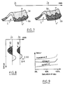
- La figure 7 est un exemple d'une répartition différente des fluides dans le réservoir de la figure 1 à deux dates différentes.
- La figure 8 représente deux traces sismiques enregistrées à la verticale d'un trou de la grille de la figure 1 pour les deux dates de la figure 7, et traitées selon l'invention.
- La figure 9 représente un modèle des variations des grandeurs caractéristiques de la réflectivité du réservoir de la figure 7 en fonction de la saturation en eau dans le réservoir.
- Figure 1 is a perspective diagram of a section of land with partial cutaway, showing the installation for implementing the method according to the invention.
- FIG. 2 is a detailed view of a hole comprising the receivers allowing the recording of direct and reflected waves according to the method of acquisition and processing of seismic data according to the invention.
- FIG. 3 is a diagram showing the direct and reflected seismic waves recorded by each of the receivers in FIG. 2.
- FIG. 4 is the visualization of the 0-phase trace obtained after processing for each of the receptors in FIG. 2.
- FIG. 5 shows the 0-phase trace with zero offset of low coverage obtained after addition of the 0-phase traces obtained in FIG. 4.
- FIG. 6 shows the correspondence between this 0-phase trace with zero offset, of low coverage obtained after treatment for the hole in FIG. 2 and the values of the reflectivity of the interfaces of the subsoil vertical to said hole.
- Figure 7 is an example of a different distribution of fluids in the tank of Figure 1 on two different dates.
- FIG. 8 represents two seismic traces recorded vertically from a hole in the grid of FIG. 1 for the two dates in FIG. 7, and treated according to the invention.
- FIG. 9 represents a model of the variations of the quantities characteristic of the reflectivity of the reservoir of FIG. 7 as a function of the water saturation in the reservoir.
Sur la figure 1, on a représenté un exemple de portion de terrain, avec une vue partielle du sous-sol. En partant de la surface du terrain vers les couches profondes du sous-sol, on distingue tout d'abord une zone d'altération superficielle 2 qui s'étend en profondeur sur 70 mètres environ et un réservoir 1 situé à environ 1200 mètres de profondeur, contenant des fluides non représentés sur cette figure, tels que par exemple de l'eau et du gaz. Ce réservoir 1, vu en tranche, s'étend sur toute la longueur de la portion de terrain représentée. En outre, on distingue sur la figure 1 la mise en oeuvre d'un enregistrement à partir de la méthode d'acquisition et de traitement de données sismiques selon l'invention, visant à suivre notamment les déplacements des fluides dans le réservoir 1.In Figure 1, an example of a portion of land is shown, with a partial view of the basement. Starting from the surface of the ground towards the deep layers of the subsoil, there is first of all a
En ce qui concerne l'acquisition des données sismiques, suivant cette méthode, comme on peut le voir sur la figure 1, on aménage à chaque point A d'une grille prédéterminée en surface, un trou 100 d'axe vertical U-U' et de faible profondeur dans le sous-sol au-dessus du réservoir 1. Les points A de la grille sont plus ou moins espacés les uns des autres, ici par exemple de 250 à 500 mètres, de manière à échantillonner correctement le réservoir 1. Ici, la grille comporte une vingtaine de points A. Chaque trou 100 de la grille s'étend à partir de la surface jusqu'à une profondeur ici d'environ 150 mètres, à l'intérieur d'un milieu dans lequel les ondes sismiques se propagent de préférence à vitesse constante et qui se trouve sous la zone d'altération superficielle 2. Ces trous 100 non tubés ou comportant une simple chemise en polychlorure de vinyle par exemple, sont réalisés avec les foreuses classiques utilisées pour la préparation des carottages V.T, nécessaires à la mesure des temps de propagation dans les niveaux superficiels. Chaque trou 100 présente un diamètre d'environ 10 centimètres.As regards the acquisition of seismic data, according to this method, as can be seen in FIG. 1, there is provided at each point A with a predetermined grid on the surface, a
Comme on peut le voir sur les figures 1 et 2, dans chaque trou 100, on positionne suivant son axe vertical U-U' au moins six à huit récepteurs 101,102,103,104,105,106,107,108, qui sont connectés séparément jusqu'à la surface. Ces récepteurs sont distants dans le trou de deux à dix mètres environ en fonction de la vitesse des ondes émises dans le milieu environnant les récepteurs et de la fréquence des ondes émises. Les récepteurs sont descendus et cimentés directement dans chaque trou 100, afin qu'ils soient fixés dans ledit trou. Chaque récepteur est muni d'un boîtier renforçant son étanchéité et est relié à la surface à une ou plusieurs prises imperméables situées sous un regard 110 placé en surface. Lorsqu'on effectue une mesure sur un trou, comme cela sera explicité ultérieurement, les récepteurs du trou en question sont alors connectés séparément à un enregistreur 300 qui vient se brancher sur la ou les prises imperméables situées sous le regard 110. Les récepteurs utilisés sont par exemple des géophones ou bien des triphones. Pour des raisons d'encombrement, les triphones peuvent être constitués de trois mini-capteurs séparés, disposés dans un tube plastique. Leur orientation dans le trou pourra être déterminée par rapport à la direction d'une émission réalisée en surface avec un certain déport.As can be seen in Figures 1 and 2, in each
Comme le montre les figures 1 et 2, dans une étape suivante de la méthode selon l'invention, on émet pour chaque trou 100, des ondes sismiques dans le sous-sol au moyen d'une source émettrice 200 placée en surface à proximité de la verticale U-U' de chaque trou 100. Ici la source émettrice 200 est placée à environ 20 mètres de la verticale du trou en question. On réalise de préférence à chaque enregistrement plusieurs émissions, soit sur place pour améliorer le rapport signal sur bruit des enregistrements, soit en se décalant progressivement de manière à obtenir une collection de traces autour de la verticale U-U' du trou 100. Cependant, la faible profondeur des récepteurs peut limiter l'efficacité du traitement proposé à des déports ne dépassant pas la profondeur moyenne de ces récepteurs, soit ici environ 100 mètres de part et d'autre du trou 100.As shown in FIGS. 1 and 2, in a following step of the method according to the invention, for each
Comme le montre les figures 2 et 3, chaque émission est à l'origine sur chacun des récepteurs du trou 100 enregistrés séparément, d'une arrivée directe d'onde incidente directe ou onde descendante 10, et d'arrivées d'ondes réfléchies aux interfaces du sous-sol, formées notamment par les fluides du réservoir 1, ou ondes montantes 20. Les ondes sont enregistrées et transmises à l'enregistreur 300.As shown in FIGS. 2 and 3, each emission is at the origin on each of the receivers of the
Ainsi, chaque émission ou groupe d'émissions sur chaque trou fournit un ou plusieurs enregistrements sismiques à une date donnée qui vont permettre de mesurer la réflectivité du sous-sol à la verticale de chaque trou. Le ou les enregistrements obtenus à une date donnée sont transformés pour chaque trou suivant les étapes de traitement de la méthode selon l'invention. Il convient de noter que dans le cadre d'une surveillance répétitive, les dates de prise de mesures ou d'enregistrements sismiques peuvent être espacées de plusieurs mois voire de plusieurs années.Thus, each emission or group of emissions on each hole provides one or more seismic recordings on a given date which will make it possible to measure the reflectivity of the subsoil vertically from each hole. The record or records obtained on a given date are transformed for each hole according to the processing steps of the method according to the invention. It should be noted that in the context of repetitive monitoring, the dates for taking seismic measurements or recordings can be spaced several months or even several years apart.
Nous allons maintenant décrire les étapes de traitement de la méthode selon l'invention pour une émission à proximité d'un trou, celles-ci étant montrées plus particulièrement sur les figures 4, 5 et 6.We will now describe the processing steps of the method according to the invention for an emission near a hole, these being shown more particularly in FIGS. 4, 5 and 6.
Pour chaque trou, on pointe les arrivées premières des ondes incidentes directes 10 de manière à mesurer le temps de propagation de ces ondes, jusqu'aux différents récepteurs. Ces délais sont ensuite utilisés de deux façons : ils sont ajoutés aux temps d'arrivée des différentes ondes réfléchies 20, ce qui a pour effet de les horizontaliser ; ils servent à identifier et à corriger les variations saisonnières de vitesse dans la zone d'altération superficielle. On sépare ensuite les ondes montantes (réfléchies) 20 et les ondes descendantes (directes) 10 par un filtrage en fréquence et en nombre d'ondes sachant que lesdites ondes montantes et descendantes ne présentent pas la même vitesse apparente. Puis, on déconvolue récepteur par récepteur les ondes montantes ou réfléchies 20 par l'onde descendante ou directe 10 arrivant au récepteur en question afin d'obtenir pour chaque récepteur une trace 0-phase 30, comme le montre la figure 4. Ces traces 0-phase présentent des réflexions dont les temps de propagation et les amplitudes maximales ou minimales sont proportionnels à la profondeur et à la réflectivité des différentes interfaces du sous-sol et sont indépendants des conditions de surface après correction des variations. Il convient de préciser que la réussite de cette déconvolution suppose que les ondes montantes 20 et descendantes 10 soient presque entièrement modelées lors de leur passage à travers la zone d'altération superficielle. C'est la condition pour que l'onde descendante 10 soit représentative des ondes montantes 20, dont le trajet sous ladite zone d'altération 2 est beaucoup plus long que celui des ondes descendantes 10, et donc que la déconvolution soit efficace. Dans l'exemple proposé, les ondes descendantes parcourent environ 100 mètres alors que les ondes montantes parcourent environ 2000 à 2500 mètres. Dans la méthode PSV, où les récepteurs sont descendus dans le puits jusqu'à proximité du réservoir, cette différence de trajet est beaucoup moins importante.For each hole, the first arrivals of the direct incident waves 10 are pointed so as to measure the propagation time of these waves, to the various receivers. These delays are then used in two ways: they are added to the arrival times of the various reflected
Par suite, après addition des traces 0-phase horizontalisées, on obtient une trace 0-phase à déport nul de faible couverture 40, comme le montre la figure 5, c'est-à-dire que pour cette nouvelle trace 40 tout se passe comme si la propagation des ondes s'était effectuée à la verticale dudit trou. La figure 6 montre la correspondance entre cette trace 0-phase à déport nul 40, et la réflectivité R1,R2 des interfaces profondes du sous-sol autour du trou 100 considéré. Il convient de noter que selon la méthode d'acquisition et de traitement décrite ici, on peut à la fois, compenser les modifications saisonnières des temps de propagation dans la zone d'altération superficielle grâce à la mesure des délais sur les ondes descendantes 10 (pointé des arrivées premières), et tenir compte des variations d'amplitude de l'émission grâce à la déconvolution, c'est-à-dire que l'on peut faire abstraction de toutes les variations superficielles d'une acquisition sur l'autre.As a result, after adding the horizontalized 0-phase traces, a 0-phase trace with zero offset of
Selon le mode de réalisation décrit aux figures 1, 2, 3, 4, 5 et 6, la méthode d'acquisition et de traitement de données sismiques permet, d'une part, à une date donnée d'obtenir un échantillonnage de la réflectivité du sous-sol suivant la grille représentée sur la figure 1. D'autre part, elle permet en répétant à des dates espacées dans le temps J1 et J2 les émissions sismiques à proximité des différents trous 100 de la grille, et en comparant pour chaque trou les différentes traces 0-phase à déport nul obtenues à l'issue du traitement, d'obtenir une évaluation des variations de saturation des fluides dans le réservoir 1 répartie de façon discrète.According to the embodiment described in Figures 1, 2, 3, 4, 5 and 6, the method of acquisition and processing of seismic data allows, on the one hand, on a given date to obtain a sampling of the reflectivity of basement according to the grid shown in Figure 1. On the other hand, it allows by repeating on dates spaced in time J 1 and J 2 the seismic emissions near the
Par exemple, comme le montre la figure 7, on suppose que le réservoir 1 comporte deux fluides 1a, 1b, tels que du gaz et de l'eau séparés par une transition progressive, qui entre des dates J1 et J2 se déplacera vers le haut par suite de la production du gaz. A la date J1 et sur une verticale U-U', le réservoir I comporte une saturation en hydrocarbure d'environ 60 %, et une saturation en eau de 40 %, tandis qu'ultérieurement, à la date J2, le réservoir I présente, selon la même verticale, des saturations hydrocarbure/eau inversées par suite de la remontée de la zone de transition. En appliquant la méthode décrite sur les figures 1 à 5, aux dates J1 et J2 et plus particulièrement en effectuant une ou plusieurs émissions à proximité de chaque trou de la grille, aux dates J1 et J2, en traitant les enregistrements obtenus et en comparant pour chaque trou les traces à déport nul, comme nous l'avons décrit précédemment, on obtient pour ce trou le diagramme de la figure 8 qui montre, d'une part une variation ΔA des amplitudes maximales ou minimales proportionnelles à la variation ΔR de la réflectivité des interfaces des couches profondes à la verticale du trou (donc à la variation ΔZ d'impédance accoustique) et d'autre part, une variation de temps de propagation Δt jusqu'à l'interface considérée qui traduit une variation de vitesse sismique dans les couches traversées par les ondes réfléchies 20.For example, as shown in FIG. 7, it is assumed that the
A partir de l'utilisation de diagrammes théoriques du type de celui représenté figure 9, il est possible de relier les variations d'impédance ΔZ ou de vitesse V, mesurées à partir de Δ A et Δ t, à des variations de saturation en fluides et donc aux déplacements de ceux-ci.From the use of theoretical diagrams of the type represented in FIG. 9, it is possible to relate the variations in impedance ΔZ or speed V, measured from Δ A and Δ t, to variations in fluid saturation. and therefore to their movements.
La méthode d'acquisition et de traitement de données sismiques décrite ci-dessus peut être réalisée dans le milieu marin. Chaque point de la grille correspondrait alors à une flûte verticale comportant plusieurs hydrophones ou groupes à hydrophones, immergée au-dessus du fond et reliée à un enregistreur autonome située dans une sphère étanche. Les émissions sont réalisées à l'aplomb de la flûte à partir d'un navire sismique qui récupère l'ensemble traceur et enregistreur après chaque acquisition.The method of acquisition and processing of seismic data described above can be carried out in the marine environment. Each point of the grid would then correspond to a vertical flute comprising several hydrophones or groups of hydrophones, immersed above the bottom and connected to an autonomous recorder located in a sealed sphere. The transmissions are made directly above the flute from a seismic vessel which collects the plotter and recorder unit after each acquisition.
Claims (2)
- Method of acquiring and processing seismic data for repetitive monitoring of displacement of fluids impregnating a reservoir (1) deep in the sub-surface below a surface weathered zone (2), characterised in that it comprises the steps of:a) making at each point (A) of a predetermined grid on the surface a vertical axis (U-U') shallow borehole (100) in the sub-surface above the reservoir (1) passing through the surface weathered zone (2),b) positioning in each borehole (100) along its vertical axis (U-U') a plurality of fixed receivers (101, 102, 103, 104, 105, 106, 107, 108) adapted to be connected separately to a recorder (300) on the surface,c) emitting near each borehole seismic waves into the sub-surface by means of an emitter (200) on the surface near the vertical axis (U-U') of said borehole (100),d) recording for each borehole by means of the receivers (101, 102, 103, 104, 105, 106, 107, 108) placed in said borehole (100) the direct incident seismic waves (10) and the seismic waves (20) reflected at the interfaces of deep strata of the sub-surface, each receiver providing a separate record of an incident wave (10) and a plurality of reflected waves (20),e) carrying out the following processing for each borehole (100):- picking the first break of direct incident waves (10),- horizontalising the reflected waves (20),- separating the reflected waves (20) and the direct incident waves (10),- deconvoluting receiver by receiver the reflected waves (20) by the direct incident wave (10) in order to obtain a 0-phase trace for each receiver,- stacking the 0-phase traces from the receivers to obtain a low coverage zero offset 0-phase trace.
- Method according to claim 1 characterised in that the emission of seismic waves into the sub-surface is repeated at each borehole at different dates (J1, J2) and said low coverage zero offset 0-phase traces obtained from emissions at the different dates (J1, J2) are compared, correcting any variations in travel time in said traces related to seasonal changes in the surface weathered zone and calculating amplitude and travel time differences at respective reflections on said traces in the sub-surface to obtain information on the displacement of the fluids in the reservoir under study.
Applications Claiming Priority (2)
| Application Number | Priority Date | Filing Date | Title |
|---|---|---|---|
| FR9211530A FR2696241B1 (en) | 1992-09-28 | 1992-09-28 | Method of acquisition and processing of seismic data recorded on receivers arranged vertically in the basement in order to follow the movement of fluids in a tank. |
| FR9211530 | 1992-09-28 |
Publications (2)
| Publication Number | Publication Date |
|---|---|
| EP0591037A1 EP0591037A1 (en) | 1994-04-06 |
| EP0591037B1 true EP0591037B1 (en) | 1997-02-12 |
Family
ID=9433954
Family Applications (1)
| Application Number | Title | Priority Date | Filing Date |
|---|---|---|---|
| EP93402355A Expired - Lifetime EP0591037B1 (en) | 1992-09-28 | 1993-09-27 | Method for obtaining and treating data for monitoring the movement of fluids in a reservoir |
Country Status (3)
| Country | Link |
|---|---|
| US (1) | US5461594A (en) |
| EP (1) | EP0591037B1 (en) |
| FR (1) | FR2696241B1 (en) |
Cited By (1)
| Publication number | Priority date | Publication date | Assignee | Title |
|---|---|---|---|---|
| CZ302965B6 (en) * | 2000-02-14 | 2012-01-25 | Gaz De France | Method for seismic monitoring of an underground zone by simultaneous use of several vibroseismic sources |
Families Citing this family (23)
| Publication number | Priority date | Publication date | Assignee | Title |
|---|---|---|---|---|
| FR2728973A1 (en) * | 1994-12-29 | 1996-07-05 | Inst Francais Du Petrole | METHOD AND DEVICE FOR THE LONG-TERM SEISMIC MONITORING OF AN UNDERGROUND AREA CONTAINING FLUIDS |
| US6065538A (en) * | 1995-02-09 | 2000-05-23 | Baker Hughes Corporation | Method of obtaining improved geophysical information about earth formations |
| GB2334104B (en) * | 1996-10-09 | 2001-02-28 | Baker Hughes Inc | Method of obtaining improved geophysical information about earth formations |
| US5946271A (en) * | 1997-03-21 | 1999-08-31 | Western Atlas International, Inc. | Calibration system for use in time lapse tomography |
| FR2766929B1 (en) * | 1997-07-30 | 1999-10-22 | Daniel Odin | SISMIC EXCITATION SOURCE FOR THE EXPLORATION OF A GEOLOGICAL STRUCTURE, SEISMIC EXPLORATION INSTALLATION OF A GEOLOGICAL STRUCTURE AND GEOLOGICAL CAVITY MONITORING EQUIPMENT |
| US5886255A (en) * | 1997-10-14 | 1999-03-23 | Western Atlas International, Inc. | Method and apparatus for monitoring mineral production |
| US6041018A (en) * | 1997-11-13 | 2000-03-21 | Colorado School Of Mines | Method for correcting amplitude and phase differences between time-lapse seismic surveys |
| FR2772137B1 (en) * | 1997-12-08 | 1999-12-31 | Inst Francais Du Petrole | SEISMIC MONITORING METHOD OF AN UNDERGROUND ZONE DURING OPERATION ALLOWING BETTER IDENTIFICATION OF SIGNIFICANT EVENTS |
| US5996726A (en) * | 1998-01-29 | 1999-12-07 | Gas Research Institute | System and method for determining the distribution and orientation of natural fractures |
| FR2775349B1 (en) * | 1998-02-20 | 2000-04-07 | Inst Francais Du Petrole | METHOD AND DEVICE FOR THE PERMANENT MONITORING OF A SUBTERRANEAN FORMATION |
| US6580751B1 (en) | 2000-02-01 | 2003-06-17 | Halliburton Energy Services, Inc. | High speed downhole communications network having point to multi-point orthogonal frequency division multiplexing |
| US6244375B1 (en) | 2000-04-26 | 2001-06-12 | Baker Hughes Incorporated | Systems and methods for performing real time seismic surveys |
| US6662899B2 (en) | 2000-04-26 | 2003-12-16 | Baker Hughes Incorporated | Use of autonomous moveable obstructions as seismic sources |
| US6374913B1 (en) | 2000-05-18 | 2002-04-23 | Halliburton Energy Services, Inc. | Sensor array suitable for long term placement inside wellbore casing |
| US6788065B1 (en) | 2000-10-12 | 2004-09-07 | Schlumberger Technology Corporation | Slotted tubulars for subsurface monitoring in directed orientations |
| US6622794B2 (en) | 2001-01-26 | 2003-09-23 | Baker Hughes Incorporated | Sand screen with active flow control and associated method of use |
| US8208341B2 (en) * | 2003-11-14 | 2012-06-26 | Schlumberger Technology Corporation | Processing of combined surface and borehole seismic data |
| US7508733B2 (en) * | 2003-11-14 | 2009-03-24 | Schlumberger Technology Corporation | High-frequency processing of seismic vibrator data |
| US20060081412A1 (en) * | 2004-03-16 | 2006-04-20 | Pinnacle Technologies, Inc. | System and method for combined microseismic and tiltmeter analysis |
| CN1969199A (en) * | 2004-04-21 | 2007-05-23 | 顶峰技术公司 | Microseismic fracture mapping using seismic source timing measurements for velocity calibration |
| US8467264B2 (en) | 2008-06-03 | 2013-06-18 | Westerngeco L.L.C. | Acquiring near zero offset survey data |
| CA2842398C (en) | 2011-08-23 | 2017-11-28 | Exxonmobil Upstream Research Company | Estimating fracture dimensions from microseismic data |
| CN105629308B (en) * | 2014-11-07 | 2017-09-12 | 中国石油化工股份有限公司 | Phased heterogeneous mechanics parameter crustal stress method |
Family Cites Families (6)
| Publication number | Priority date | Publication date | Assignee | Title |
|---|---|---|---|---|
| US2900037A (en) * | 1954-07-15 | 1959-08-18 | Sun Oil Co | Seismographic exploration |
| US3371310A (en) * | 1966-03-14 | 1968-02-27 | Pan American Petroleum Corp | Discriminating between primary and multiple seismic reflections |
| FR2558602B1 (en) * | 1984-01-19 | 1986-05-30 | Petroles Cie Francaise | METHOD FOR OBTAINING AND COMPUTER PROCESSING OF SEISMIC DATA RECORDED FROM AN EXPLORATION WELL |
| US5191557A (en) * | 1986-12-30 | 1993-03-02 | Gas Research Institute | Signal processing to enable utilization of a rig reference sensor with a drill bit seismic source |
| NO166903C (en) * | 1987-06-02 | 1991-09-11 | Geco As | PROCEDURES FOR VERTICAL SEISMIC PROFILING (VSP). |
| US5253217A (en) * | 1989-04-14 | 1993-10-12 | Atlantic Richfield Company | Method for seismic exploration including compensation for near surface effects |
-
1992
- 1992-09-28 FR FR9211530A patent/FR2696241B1/en not_active Expired - Fee Related
-
1993
- 1993-09-27 EP EP93402355A patent/EP0591037B1/en not_active Expired - Lifetime
- 1993-09-27 US US08/127,246 patent/US5461594A/en not_active Expired - Lifetime
Cited By (1)
| Publication number | Priority date | Publication date | Assignee | Title |
|---|---|---|---|---|
| CZ302965B6 (en) * | 2000-02-14 | 2012-01-25 | Gaz De France | Method for seismic monitoring of an underground zone by simultaneous use of several vibroseismic sources |
Also Published As
| Publication number | Publication date |
|---|---|
| FR2696241B1 (en) | 1994-12-30 |
| US5461594A (en) | 1995-10-24 |
| EP0591037A1 (en) | 1994-04-06 |
| FR2696241A1 (en) | 1994-04-01 |
Similar Documents
| Publication | Publication Date | Title |
|---|---|---|
| EP0591037B1 (en) | Method for obtaining and treating data for monitoring the movement of fluids in a reservoir | |
| Yu et al. | Walkaway VSP using multimode optical fibers in a hybrid wireline | |
| Lavergne et al. | Inversion of seismograms and pseudo velocity logs | |
| US4894807A (en) | Simultaneous vertical-seismic profiling and surface seismic acquisition method | |
| US6529445B1 (en) | Method of reducing effects of a rough sea surface on seismic data | |
| US10690792B2 (en) | Amplitude-versus-angle analysis for quantitative interpretation | |
| RU2321026C2 (en) | Definition of height of surface of liquid column | |
| EP2253970B1 (en) | Method for imaging a target area of the subsoil using walkaway data | |
| US6894949B2 (en) | Walkaway tomographic monitoring | |
| EA005228B1 (en) | A method of processing seismic data | |
| CA2733882A1 (en) | Method for monitoring a geological gas storage site by stratigraphic inversion of seismic data | |
| FR2918178A1 (en) | METHOD FOR ADJUSTING A SEISMIC WAVE SPEED MODEL BASED ON INFORMATION RECORDED AT WELLS | |
| Andreassen et al. | Multicomponent ocean bottom cable data in gas hydrate investigation offshore of Norway | |
| US4415997A (en) | Method for determining source and receiver statics in marine seismic exploration | |
| CA2464799A1 (en) | Method of determining a model for seismic wave velocity in a heterogeneous subsurface formation | |
| Knapp et al. | Imaging through gas clouds: A case history from the Gulf of Mexico | |
| FR2616919A1 (en) | METHOD AND DEVICE FOR THE SEISMIC PROSPECTION OF A MEDIUM FROM INDUCED WAVES CREATED ARTIFICIALLY IN A WELL | |
| Amos et al. | Origin of shore‐normal channels from the shoreface of Sable Island, Canada | |
| CA2107153C (en) | Method for obtaining and processing seismic data recorded from sensors installed vertically in the underground to follow the movement of fluids in an underground reservoir | |
| US6263285B1 (en) | Amplitude spectra estimation | |
| EP0371870B1 (en) | Method and apparatus for acquiring and treating signals obtained in boreholes, especially in horizontal boreholes | |
| Boucher et al. | Seismic evidence for an extensive gas-bearing layer at shallow depth, offshore from Prudhoe Bay, Alaska | |
| Miller et al. | High resolution seismic reflection images of New Jersey coastal aquifers | |
| CN110050204B (en) | Method for improving seismic acquisition using active ultra-light seismic detection system | |
| Wardaya et al. | Imaging of Subsurface Velocity Structure on Volcanic Area of South East Java: An Application of Passive Seismic Ambient Noise Tomography for Sub-Volcanic Hydrocarbon Exploration |
Legal Events
| Date | Code | Title | Description |
|---|---|---|---|
| PUAI | Public reference made under article 153(3) epc to a published international application that has entered the european phase |
Free format text: ORIGINAL CODE: 0009012 |
|
| AK | Designated contracting states |
Kind code of ref document: A1 Designated state(s): FR GB IT |
|
| 17P | Request for examination filed |
Effective date: 19940808 |
|
| GRAG | Despatch of communication of intention to grant |
Free format text: ORIGINAL CODE: EPIDOS AGRA |
|
| 17Q | First examination report despatched |
Effective date: 19960328 |
|
| GRAH | Despatch of communication of intention to grant a patent |
Free format text: ORIGINAL CODE: EPIDOS IGRA |
|
| GRAH | Despatch of communication of intention to grant a patent |
Free format text: ORIGINAL CODE: EPIDOS IGRA |
|
| GRAA | (expected) grant |
Free format text: ORIGINAL CODE: 0009210 |
|
| AK | Designated contracting states |
Kind code of ref document: B1 Designated state(s): FR GB IT |
|
| ITF | It: translation for a ep patent filed |
Owner name: 0403;68MIFCON LOR S.R.L. |
|
| GBT | Gb: translation of ep patent filed (gb section 77(6)(a)/1977) |
Effective date: 19970407 |
|
| PLBE | No opposition filed within time limit |
Free format text: ORIGINAL CODE: 0009261 |
|
| STAA | Information on the status of an ep patent application or granted ep patent |
Free format text: STATUS: NO OPPOSITION FILED WITHIN TIME LIMIT |
|
| 26N | No opposition filed | ||
| REG | Reference to a national code |
Ref country code: GB Ref legal event code: IF02 |
|
| PG25 | Lapsed in a contracting state [announced via postgrant information from national office to epo] |
Ref country code: IT Free format text: LAPSE BECAUSE OF NON-PAYMENT OF DUE FEES;WARNING: LAPSES OF ITALIAN PATENTS WITH EFFECTIVE DATE BEFORE 2007 MAY HAVE OCCURRED AT ANY TIME BEFORE 2007. THE CORRECT EFFECTIVE DATE MAY BE DIFFERENT FROM THE ONE RECORDED. Effective date: 20050927 |
|
| PGFP | Annual fee paid to national office [announced via postgrant information from national office to epo] |
Ref country code: GB Payment date: 20081022 Year of fee payment: 16 |
|
| GBPC | Gb: european patent ceased through non-payment of renewal fee |
Effective date: 20090927 |
|
| PG25 | Lapsed in a contracting state [announced via postgrant information from national office to epo] |
Ref country code: GB Free format text: LAPSE BECAUSE OF NON-PAYMENT OF DUE FEES Effective date: 20090927 |
|
| PGFP | Annual fee paid to national office [announced via postgrant information from national office to epo] |
Ref country code: FR Payment date: 20100923 Year of fee payment: 18 |
|
| REG | Reference to a national code |
Ref country code: FR Ref legal event code: ST Effective date: 20120531 |
|
| PG25 | Lapsed in a contracting state [announced via postgrant information from national office to epo] |
Ref country code: FR Free format text: LAPSE BECAUSE OF NON-PAYMENT OF DUE FEES Effective date: 20110930 |