EP0590987B1 - Determining orientation of a wellbore relative to formation stress fields - Google Patents
Determining orientation of a wellbore relative to formation stress fields Download PDFInfo
- Publication number
- EP0590987B1 EP0590987B1 EP93307783A EP93307783A EP0590987B1 EP 0590987 B1 EP0590987 B1 EP 0590987B1 EP 93307783 A EP93307783 A EP 93307783A EP 93307783 A EP93307783 A EP 93307783A EP 0590987 B1 EP0590987 B1 EP 0590987B1
- Authority
- EP
- European Patent Office
- Prior art keywords
- pressure
- formation
- relative
- boreholes
- relief
- Prior art date
- Legal status (The legal status is an assumption and is not a legal conclusion. Google has not performed a legal analysis and makes no representation as to the accuracy of the status listed.)
- Expired - Lifetime
Links
Images


Classifications
-
- E—FIXED CONSTRUCTIONS
- E21—EARTH OR ROCK DRILLING; MINING
- E21B—EARTH OR ROCK DRILLING; OBTAINING OIL, GAS, WATER, SOLUBLE OR MELTABLE MATERIALS OR A SLURRY OF MINERALS FROM WELLS
- E21B43/00—Methods or apparatus for obtaining oil, gas, water, soluble or meltable materials or a slurry of minerals from wells
- E21B43/25—Methods for stimulating production
- E21B43/26—Methods for stimulating production by forming crevices or fractures
-
- E—FIXED CONSTRUCTIONS
- E21—EARTH OR ROCK DRILLING; MINING
- E21B—EARTH OR ROCK DRILLING; OBTAINING OIL, GAS, WATER, SOLUBLE OR MELTABLE MATERIALS OR A SLURRY OF MINERALS FROM WELLS
- E21B47/00—Survey of boreholes or wells
- E21B47/02—Determining slope or direction
-
- E—FIXED CONSTRUCTIONS
- E21—EARTH OR ROCK DRILLING; MINING
- E21B—EARTH OR ROCK DRILLING; OBTAINING OIL, GAS, WATER, SOLUBLE OR MELTABLE MATERIALS OR A SLURRY OF MINERALS FROM WELLS
- E21B49/00—Testing the nature of borehole walls; Formation testing; Methods or apparatus for obtaining samples of soil or well fluids, specially adapted to earth drilling or wells
- E21B49/006—Measuring wall stresses in the borehole
-
- E—FIXED CONSTRUCTIONS
- E21—EARTH OR ROCK DRILLING; MINING
- E21B—EARTH OR ROCK DRILLING; OBTAINING OIL, GAS, WATER, SOLUBLE OR MELTABLE MATERIALS OR A SLURRY OF MINERALS FROM WELLS
- E21B49/00—Testing the nature of borehole walls; Formation testing; Methods or apparatus for obtaining samples of soil or well fluids, specially adapted to earth drilling or wells
- E21B49/008—Testing the nature of borehole walls; Formation testing; Methods or apparatus for obtaining samples of soil or well fluids, specially adapted to earth drilling or wells by injection test; by analysing pressure variations in an injection or production test, e.g. for estimating the skin factor
Definitions
- the present invention relates generally to the determination of fracture orientation relative to a wellbore and relative to formation stress fields, and more specifically to such methods performed in response to analysis of pressures observed during a fracturing operation.
- test fracturing operations to determine reservoir or formation characteristics prior to the performance of a full scale fracturing operation is well-known.
- evaluation of a formation through use of a test fracturing operation performed through use of a fracturing fluid without proppant is well-known.
- Exemplary procedures of this type are those normally referred to in the industry as "minifrac” or "microfrac” operations.
- a short interval of a wellbore is pressurized until a "breakdown" of the formation occurs.
- the formation will break down when the pressure at the formation reaches a "breakdown pressure," i.e. that pressure at which the tangential stress changes from compression into tension and reaches the tensile strength of the formation. At this point, the formation will yield to the stress, and a tensile fracture will be created.
- breakdown pressure i.e. that pressure at which the tangential stress changes from compression into tension and reaches the tensile strength of the formation.
- the formation will yield to the stress, and a tensile fracture will be created.
- the characteristics of the monitored pressure curve will depend upon the fluid injection rate and the fluid leak-off rate.
- the fracture will extend, and the extension pressure may either increase or decrease, depending upon any height restriction on fracture propagation and fluid leak-off.
- the injection will be ceased, and an instantaneous shut-in pressure will be recorded.
- This parameter will yield information regarding frictional pressure during the injection operation. Pressure decline after shut-in well will be monitored, and the closure pressure will be determined. The closure pressure is that pressure at which the created fracture will close. This pressure will be equivalent to the minimum horizontal stress within the formation. If the shut-in is continued for an extended period, the formation will eventually reach an equilibrium pressure, at which time the pressure will be equal to the initial reservoir pressure.
- a conventional "minifrac" or "microfrac” method is disclosed in EP-A-476758.
- the present invention provides a new method of utilizing observed pressure data during a test fracturing operation to determine the fracture direction relative to stress fields in the formation surrounding the wellbore.
- the method of the present invention may also be particularly useful in deviated or horizontal wells to determine the direction of the fracture relative to the wellbore direction.
- a method of determining the azimuthal direction of a deviated borehole relative to stress fields within a formation comprises the steps of:
- each of said at least three boreholes is deviated relative to a generally common, generally vertical axis.
- each of said at least three boreholes extends generally horizontally proximate the formation to which pressure is being applied.
- the method may also include the further step of determining the azimuthal relationship of the fracture induced from the deviated borehole relative to one of the at least two additional deviated boreholes.
- the present invention provides a method of determining the azimuthal direction of a deviated borehole relative to stress fields within a formation.
- the deviated borehole will be one of at least three boreholes which extend in a known angular relation to one another at least proximate a portion of their extent within a formation. This type of data may typically be obtained through use of conventional well surveys.
- fluid pressure will be individually applied in each of the boreholes proximate a selected formation to establish a breakdown pressure in the formation so as to establish a fracture in the formation and a relief in pressure after the breakdown pressure is reached.
- the pressure will be monitored, at least during the time that the breakdown pressure is achieved and a time at which the relief in pressure occurs.
- the derivative of the relief in pressure will be determined for each of the three wells.
- the derivative of the relief in pressure for each of the three wells will be functionally related, such as through use of a graphical plot, relative to the known angular relation between the wells proximate the formation under examination.
- the derivatives of the relief in pressure for the three wells will define coordinates which are indicative of the actual angular deviation of one or more of the wells relative to the minimal and maximal stress fields within the formation. This information will also be indicative of the actual direction of fracture propagation. Accordingly, the direction of the stress fields and fracture propagation relative to the known well azimuth in a particular formation will also provide data representative of the fracture azimuth within the formation.
- Fig. 1 graphically represents pressures observed during a conventional test fracturing operation.
- Fig. 2 graphically depicts a representation representative of a test procedure wherein the profile of the relief and pressure curve was observed for different orientations of wellbores within a fractured simulated formation.
- Fig. 3 graphically depicts an alternative representation representative of a test procedure wherein the profile of the relief and pressure curve was observed for different orientations of wellbores within a fractured simulated formation.
- Fig. 4 graphically depicts an exemplary graphical representation of a solution for a well azimuth relative to formation stress fields in accordance with the present invention.
- Fig. 5 graphically depicts an exemplary graphical representation of a solution for a well azimuth relative to formation stress fields in accordance with the present invention.
- Fig. 6 graphically depicts an exemplary graphical representation of a solution for a well azimuth relative to formation stress fields in accordance with the present invention.
- a curve 10 of pressure behaviour during a typical microfrac test fracturing procedure pressure will be applied in the wellbore 12 during the microfrac. As can be seen from curve 10, pressure will be applied until the time 14 when the breakdown pressure is achieved and a fracture is opened. Following the breakdown pressure 14, there is a relief in pressure 16 representing an abrupt drop in pressure after the breakdown pressure. Following the relief in pressure on curve 10, is the pressure decline from breakdown pressure to the extension pressure 18 for the formation. In an open hole wellbore, without substantial permeability damage, the breakdown pressure will reflect the in situ stress field around the wellbore, while the extension pressure will be controlled primarily by the minimum horizontal stress in the stress field.
- the inventors have discovered that the profile of the pressure curve proximate the relief in pressure 16 after breakdown is functionally related to fracture direction relative to stress fields in the formation surrounding a wellbore.
- Figure 2 depicts exemplary curves determined during an experimental procedure to observe pressure data in a test fixture.
- the test fixture involved a synthetic wellbore assembly, wherein hydrostone (gypsum cement) blocks of six by six by ten inches were utilized to simulate a formation under fracture.
- the blocks were cast from mixing water and hydrostone with a weight ratio of 32:100, respectively.
- a wellbore was cast in the center of the block perpendicular to the sample axis along the 0.254 m (10 inch) side.
- One sample with a vertical hole was fractured to provide reference data for a fractured vertical hole under triaxial loading conditions. All samples were confined in a triaxial loading vessel and the principal stresses applied were: 20.68 x 10 6 Pa (3,000 psi) vertical, 17.24 x 10 6 Pa (2,500 psi) maximum horizontal, and 9.65 x 10 6 Pa (1,400 psi) minimum horizontal stresses.
- Axial load was applied utilizing a 54,431 Kg (120,000 pound) Riehl universal loading machine.
- the sample was loaded in steps of 3.45 x 10 6 Pa (500 psi).
- a 3.45 x 10 6 Pa (500 psi) axial force was applied first relative to the longest dimensions of the sample.
- the horizontal stresses were then raised together to 9.65 x 10 6 Pa (1,400 psi) when vertical stress continued to 17.24 x 10 6 Pa (2,500 psi) was held.
- Axial load then continued to 20.68 x 10 6 Pa (3,000 psi). No pore pressure was present within the sample block.
- Fracturing fluid used in the tests was 30-weight motor oil with apparent viscosities of 580, 360, and 14 cp at 23.3°C (74), 28.3°C (83), and 90.5°C (195), respectively. All experiments were conducted at room temperature 23.3°C to 25.5°C (74 to 78°F) with injection rate of 30 cm 3 /min. Identical rock type, rock properties, loading conditions, fracturing fluid properties, injection rate, and fracturing treatment were used throughout the course of testing. The only variable was the wellbore orientation relative to the maximum horizontal stress. Injection was accomplished at the rate of thirty cubic centimeters per minute.
- FIG. 2 therein is shown an exemplary set of relief in pressure curves with the variable being the angular deviation of the wellbore axis relative to the minimum stress field on the test sample.
- Each curve 30, 32, 34, 36, and 38 represents the observed pressure curves when the induced fracture was oriented 90°, 60°, 45°, 30°, and 0°, respectively, from the minimum stress field.
- Fig. 3 therein are depicted seven curves, 40, 42, 44, 46, 48, 50, and 52, representing deviations of induced fractures relative to the minimum horizontal stress field of 90°, 75°, 56°, 45°, 30°, 22.5°, and 0°, respectively, as were observed during a second test procedure.
- fracturing operations including test fracturing operations such as microfrac operations, in a plurality of deviated boreholes through a formation may be utilized to determine the orientation of the stress fields within the formation, and to also determine the azimuth of each fracture.
- the relief in pressure data may be directly plotted to utilize the previously discussed linear relationship to determine the actual orientation of each fracture relative to the minimum horizontal stress field or to the maximum horizontal stress field, within the formation.
- these wellbores under examination will extend through said formation at azimuths which are preferably angularly disposed at 45° or greater relative to one another, resulting in a total span of at least 90° between the extremes.
- the relief in pressure 16 data will be data obtained during the time after breakdown 14 but clearly before the extension pressure 18 is reached.
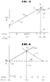
- FIG. 4 therein is depicted an exemplary graphical depiction of a solution of the determination of a primary wellbore relative to the maximum stress field in a formation.
- data points relative to three hypothetical wells, each angularly offset from one another by 45° are represented.
- the determined derivative of the relief in pressure for a first well 62, as described relative to Figs. 2 and 3 with the lowest ordinate value is plotted as the Y axis intercept deviation from the maximum stress field.
- the determined derivative for another well 64 will be plotted relative to the angular deviation of the well to which it pertains relative to the first well (45°) and will thereby define a line 66 determinative of the linear relationship between the determined relief in pressure relative to the maximum horizontal stress field.
- Another, higher derivative value 68 will then be plotted relative to its known angular deviation relative to the well from which either derivative data point 60 or 64 were derived. As can be seen in Fig. 4, point 68 lies beneath line 66. However, point 68 will facilitate in determining the offset of data points 60 and 64 relative to the actual maximum horizontal stress field.
- the ordinate coordinate 70 of point 68 may be utilized to find an intercept 72 with line 66.
- the bisecting of the offset line 74 between point 72 and point 68 will define a corrected trend line intercept 76 of which the abscissa coordinate 78 will define an angular offset relative to the deviation from the actual maximal stress field in the wellbore.
- the minimum stress field oriented at 90° to the maximum stress field
- the abscissa intercept 78 which is indicative of 80° on the established abscissa scale.
- plotting of the derivatives relative to the relative angular distribution to define a line through at least two points should define a line which provides a solution which both (a) defines a solution for the third point, as described relating to Fig. 4; and (b) provides such solution within the span of the total azimuthal difference between the wells from which the data was obtained (i.e, 90° in the example f Fig. 4).
- FIG. 5 therein is depicted an alternative exemplary solution for another hypothetical case in which relief in pressure data is obtained from three wells oriented at 0°, 45°, and 90° relative to one another.
- Data point 80 relative to a first well has been plotted on the Y axis
- a data point 82 from a representative of the determined relief in pressure derivative for a second well has been plotted relative to the known angular deviation relative to the first well
- a data point 84 has been plotted relative to the further known angular deviation from the first two wells.
- dotted trend line 86 connected through data points 80 and 82, this line will not intersect within a 90° quadrant with line 88 along the Y axis intercept of data point 84.
- Y axis can now be recognized to be 60° deviated from the maximal stress field, the point on the X axis initially assigned as 45°, will now be recognized to be 75°, and the point initially identified as 90° deviation on the X axis may now be seen to represent a 30° deviation from the maximal stress field.
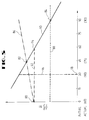
- FIG. 6 there is depicted another hypothetical example wherein data points 100 and 104, from three wells, again spaced known distances of 0°, 45°, and 90° relative to one another have been plotted.
- points 100 and 102 have been connected by a trend line 106.
- the Y axis intercept line 108 of data point 104, is thus bisected by a line 110 which passes directly through point 102. Because of this relationship, these coordinates could also have been graphically analyzed through use of a trend line 112 connecting data points 102 and 104.
Landscapes
- Geology (AREA)
- Life Sciences & Earth Sciences (AREA)
- Engineering & Computer Science (AREA)
- Mining & Mineral Resources (AREA)
- Physics & Mathematics (AREA)
- Environmental & Geological Engineering (AREA)
- Fluid Mechanics (AREA)
- General Life Sciences & Earth Sciences (AREA)
- Geochemistry & Mineralogy (AREA)
- Chemical & Material Sciences (AREA)
- Analytical Chemistry (AREA)
- Geophysics (AREA)
- Investigating Strength Of Materials By Application Of Mechanical Stress (AREA)
- Geophysics And Detection Of Objects (AREA)
Description
| Porosity = | 26.5% |
| Permeability (N2) = | 3.9 md |
| Grain density = | 2.23 gm/cc |
| Bulk density = | 1.171 gm/cc |
| Young's Modulus = | 1.43 x 10¹⁰ Pa (2.07 x 10⁶ psi) |
| Poisson's ratio = | 0.21 |
| Uniaxial compressive strength = | 55.38 x 10⁶ Pa (8032 psi) |
| Tensile strength (Brazilian) = | 5.57 x 10⁶ (807.6 psi) |
Claims (4)
- A method of determining the azimuthal direction of a deviated borehole relative to stress fields within a formation, which method comprises the steps of:(1) applying fluid pressure into a formation surrounding a deviated borehole to establish a formation breakdown pressure in said formation, to establish a fracture in said formation and a relief in pressure after said breakdown pressure is achieved;(2) monitoring the pressure proximate said formation at least proximate the time at which said breakdown pressure is achieved and at which said relief in pressure occurs; and(3) determining the derivative of said relief in pressure for the borehole characterised by;(4) repeating steps (1), (2) and (3) in each of at least two additional boreholes, each of the at least three boreholes having a known angular relation to one another proximate at least a portion of the extent of the boreholes within the formation; and(5) functionally relating the determined derivative of the relief in pressure for each of the at least three boreholes to the known angular relation between the at least three boreholes to determine an actual angular deviation of at least one of the boreholes relative to a stress field in said formation.
- A method according to claim 1, wherein each of said at least three boreholes is deviated relative to a generally common, generally vertical axis.
- A method according to claim 1 or 2, wherein each of said at least three boreholes extends generally horizontally proximate the formation to which pressure is being applied.
- A method according to claim 1, 2 or 3, including the step of determining the azimuthal relationship of the fracture induced from the deviated borehole relative to one of the at least two additional deviated boreholes.
Applications Claiming Priority (2)
| Application Number | Priority Date | Filing Date | Title |
|---|---|---|---|
| US955110 | 1992-10-01 | ||
| US07/955,110 US5285683A (en) | 1992-10-01 | 1992-10-01 | Method and apparatus for determining orientation of a wellbore relative to formation stress fields |
Publications (3)
| Publication Number | Publication Date |
|---|---|
| EP0590987A2 EP0590987A2 (en) | 1994-04-06 |
| EP0590987A3 EP0590987A3 (en) | 1995-02-22 |
| EP0590987B1 true EP0590987B1 (en) | 1998-08-05 |
Family
ID=25496397
Family Applications (1)
| Application Number | Title | Priority Date | Filing Date |
|---|---|---|---|
| EP93307783A Expired - Lifetime EP0590987B1 (en) | 1992-10-01 | 1993-09-30 | Determining orientation of a wellbore relative to formation stress fields |
Country Status (4)
| Country | Link |
|---|---|
| US (1) | US5285683A (en) |
| EP (1) | EP0590987B1 (en) |
| DE (1) | DE69320134T2 (en) |
| DK (1) | DK0590987T3 (en) |
Families Citing this family (10)
| Publication number | Priority date | Publication date | Assignee | Title |
|---|---|---|---|---|
| GB2374887B (en) | 2001-04-27 | 2003-12-17 | Schlumberger Holdings | Method and apparatus for orienting perforating devices |
| US7114564B2 (en) * | 2001-04-27 | 2006-10-03 | Schlumberger Technology Corporation | Method and apparatus for orienting perforating devices |
| WO2010008684A2 (en) * | 2008-07-15 | 2010-01-21 | Schlumberger Canada Limited | Apparatus and methods for characterizing a reservoir |
| US20110061869A1 (en) * | 2009-09-14 | 2011-03-17 | Halliburton Energy Services, Inc. | Formation of Fractures Within Horizontal Well |
| WO2013008195A2 (en) * | 2011-07-11 | 2013-01-17 | Schlumberger Canada Limited | System and method for performing wellbore stimulation operations |
| EP3134612A4 (en) * | 2014-04-30 | 2017-12-06 | Halliburton Energy Services, Inc. | Characterizing a downhole environment using stiffness coefficients |
| CN103983236B (en) * | 2014-06-01 | 2016-01-13 | 中国石油大学(华东) | Orientation method of core fracture in inclined well |
| CN106894802B (en) * | 2015-12-18 | 2020-05-15 | 中国石油化工股份有限公司 | Small-sized fracturing testing method suitable for shale gas well |
| US11414965B2 (en) | 2018-02-27 | 2022-08-16 | Schlumberger Technology Corporation | Rotating loading tube and angled shaped charges for oriented perforating |
| EP3803052A1 (en) * | 2018-05-30 | 2021-04-14 | Saudi Arabian Oil Company | Systems and methods for detection of induced micro-fractures |
Family Cites Families (7)
| Publication number | Priority date | Publication date | Assignee | Title |
|---|---|---|---|---|
| US2496422A (en) * | 1943-05-03 | 1950-02-07 | Subkow Philip | Geometrical determination of dip and strike of cored strata |
| ES345498A1 (en) * | 1966-09-29 | 1968-11-16 | Engenharia Lab Nacional | Improved Method and Apparatus for Testing the State of Stress in a Solid especially Soil |
| US4005750A (en) * | 1975-07-01 | 1977-02-01 | The United States Of America As Represented By The United States Energy Research And Development Administration | Method for selectively orienting induced fractures in subterranean earth formations |
| US4724905A (en) * | 1986-09-15 | 1988-02-16 | Mobil Oil Corporation | Sequential hydraulic fracturing |
| US4830106A (en) * | 1987-12-29 | 1989-05-16 | Mobil Oil Corporation | Simultaneous hydraulic fracturing |
| US5005643A (en) * | 1990-05-11 | 1991-04-09 | Halliburton Company | Method of determining fracture parameters for heterogenous formations |
| US5105659A (en) * | 1990-09-19 | 1992-04-21 | Dowell Schlumberger Incorporated | Detection of fracturing events using derivatives of fracturing pressures |
-
1992
- 1992-10-01 US US07/955,110 patent/US5285683A/en not_active Expired - Fee Related
-
1993
- 1993-09-30 DE DE69320134T patent/DE69320134T2/en not_active Expired - Fee Related
- 1993-09-30 EP EP93307783A patent/EP0590987B1/en not_active Expired - Lifetime
- 1993-09-30 DK DK93307783T patent/DK0590987T3/en active
Also Published As
| Publication number | Publication date |
|---|---|
| DK0590987T3 (en) | 1998-10-26 |
| US5285683A (en) | 1994-02-15 |
| DE69320134T2 (en) | 1998-12-10 |
| EP0590987A2 (en) | 1994-04-06 |
| EP0590987A3 (en) | 1995-02-22 |
| DE69320134D1 (en) | 1998-09-10 |
Similar Documents
| Publication | Publication Date | Title |
|---|---|---|
| Karev et al. | Triaxial loading system as a tool for solving geotechnical problems of oil and gas production | |
| Steiger et al. | Quantitative determination of the mechanical properties of shales | |
| US5285683A (en) | Method and apparatus for determining orientation of a wellbore relative to formation stress fields | |
| WO1996004464A1 (en) | Lightweight proppants and their use in hydraulic fracturing | |
| US4879654A (en) | Drilling fluid | |
| Scott Jr et al. | Rock rupture as affected by fluid properties | |
| Song et al. | A laboratory study of hydraulic fracturing breakdown pressure in tablerock sandstone | |
| Madyarov et al. | Understanding the impact of completion designs on multi-stage fracturing via block test experiments | |
| Wang et al. | Expansion of horizontal wellbore stability model for elastically anisotropic shale formations with anisotropic failure criteria: Permian Basin case study | |
| EP0476758B1 (en) | Detection of fracturing events using derivatives of fracturing pressures | |
| Smith et al. | The azimuth of deep, penetrating fractures in the Wattenberg field | |
| Ye et al. | Failure behavior of the Poorman schist and its fractures from EGS collab stimulation site | |
| Frash et al. | Laboratory-scale-model testing of well stimulation by use of mechanical-impulse hydraulic fracturing | |
| Read et al. | Technical summary of AECLs Mine-by Experiment phase I: Excavation response. | |
| Haimson et al. | Brittle fracture in two crystalline rocks under true triaxial compressive stresses | |
| Enever et al. | Experience with hydraulic fracture stress measurements in granite | |
| Brumley et al. | Hydraulic fracturing of deviated wells: interpretation of breakdown and initial fracture opening pressure | |
| Liu et al. | Mechanisms of crack initiation and propagation in dense linear multihole directional hydraulic fracturing | |
| US5482122A (en) | Oriented-radial-cores retrieval for measurements of directional properties | |
| Baumgartner et al. | Fracturing deviated boreholes: An experimental laboratory approach | |
| Myrvang | Estimation of in-situ compressive strength of rocks from in-situ rock stress measurements in highly stressed rock structures | |
| EP0576210B1 (en) | Determining elastic anistropy in subterranean formations | |
| Rumzan et al. | The influence of well bore fluid pressure on drilling penetration rates and stress dependent strength | |
| Mills et al. | Remote high resolution stress change monitoring for hydraulic fractures | |
| Khan et al. | Geomechanical Implications on Unconventional Reservoir Fracturing in Saudi Arabia |
Legal Events
| Date | Code | Title | Description |
|---|---|---|---|
| PUAI | Public reference made under article 153(3) epc to a published international application that has entered the european phase |
Free format text: ORIGINAL CODE: 0009012 |
|
| AK | Designated contracting states |
Kind code of ref document: A2 Designated state(s): DE DK FR GB IT NL |
|
| PUAL | Search report despatched |
Free format text: ORIGINAL CODE: 0009013 |
|
| AK | Designated contracting states |
Kind code of ref document: A3 Designated state(s): DE DK FR GB IT NL |
|
| 17P | Request for examination filed |
Effective date: 19950315 |
|
| 17Q | First examination report despatched |
Effective date: 19960820 |
|
| GRAG | Despatch of communication of intention to grant |
Free format text: ORIGINAL CODE: EPIDOS AGRA |
|
| GRAG | Despatch of communication of intention to grant |
Free format text: ORIGINAL CODE: EPIDOS AGRA |
|
| GRAH | Despatch of communication of intention to grant a patent |
Free format text: ORIGINAL CODE: EPIDOS IGRA |
|
| RAP1 | Party data changed (applicant data changed or rights of an application transferred) |
Owner name: HALLIBURTON ENERGY SERVICES, INC. |
|
| GRAH | Despatch of communication of intention to grant a patent |
Free format text: ORIGINAL CODE: EPIDOS IGRA |
|
| GRAA | (expected) grant |
Free format text: ORIGINAL CODE: 0009210 |
|
| ITF | It: translation for a ep patent filed | ||
| AK | Designated contracting states |
Kind code of ref document: B1 Designated state(s): DE DK FR GB IT NL |
|
| REF | Corresponds to: |
Ref document number: 69320134 Country of ref document: DE Date of ref document: 19980910 |
|
| ET | Fr: translation filed | ||
| REG | Reference to a national code |
Ref country code: DK Ref legal event code: T3 |
|
| PLBE | No opposition filed within time limit |
Free format text: ORIGINAL CODE: 0009261 |
|
| 26N | No opposition filed | ||
| REG | Reference to a national code |
Ref country code: GB Ref legal event code: IF02 |
|
| PGFP | Annual fee paid to national office [announced via postgrant information from national office to epo] |
Ref country code: NL Payment date: 20040905 Year of fee payment: 12 |
|
| PGFP | Annual fee paid to national office [announced via postgrant information from national office to epo] |
Ref country code: FR Payment date: 20040908 Year of fee payment: 12 |
|
| PGFP | Annual fee paid to national office [announced via postgrant information from national office to epo] |
Ref country code: DK Payment date: 20040916 Year of fee payment: 12 |
|
| PGFP | Annual fee paid to national office [announced via postgrant information from national office to epo] |
Ref country code: DE Payment date: 20040923 Year of fee payment: 12 |
|
| PGFP | Annual fee paid to national office [announced via postgrant information from national office to epo] |
Ref country code: GB Payment date: 20040929 Year of fee payment: 12 |
|
| PG25 | Lapsed in a contracting state [announced via postgrant information from national office to epo] |
Ref country code: IT Free format text: LAPSE BECAUSE OF NON-PAYMENT OF DUE FEES;WARNING: LAPSES OF ITALIAN PATENTS WITH EFFECTIVE DATE BEFORE 2007 MAY HAVE OCCURRED AT ANY TIME BEFORE 2007. THE CORRECT EFFECTIVE DATE MAY BE DIFFERENT FROM THE ONE RECORDED. Effective date: 20050930 Ref country code: GB Free format text: LAPSE BECAUSE OF NON-PAYMENT OF DUE FEES Effective date: 20050930 Ref country code: DK Free format text: LAPSE BECAUSE OF NON-PAYMENT OF DUE FEES Effective date: 20050930 |
|
| PG25 | Lapsed in a contracting state [announced via postgrant information from national office to epo] |
Ref country code: NL Free format text: LAPSE BECAUSE OF NON-PAYMENT OF DUE FEES Effective date: 20060401 Ref country code: DE Free format text: LAPSE BECAUSE OF NON-PAYMENT OF DUE FEES Effective date: 20060401 |
|
| REG | Reference to a national code |
Ref country code: DK Ref legal event code: EBP |
|
| GBPC | Gb: european patent ceased through non-payment of renewal fee |
Effective date: 20050930 |
|
| PG25 | Lapsed in a contracting state [announced via postgrant information from national office to epo] |
Ref country code: FR Free format text: LAPSE BECAUSE OF NON-PAYMENT OF DUE FEES Effective date: 20060531 |
|
| NLV4 | Nl: lapsed or anulled due to non-payment of the annual fee |
Effective date: 20060401 |
|
| REG | Reference to a national code |
Ref country code: FR Ref legal event code: ST Effective date: 20060531 |