EP0590311B1 - Rake wheel for haymaking machine especially for windrower - Google Patents
Rake wheel for haymaking machine especially for windrower Download PDFInfo
- Publication number
- EP0590311B1 EP0590311B1 EP93113626A EP93113626A EP0590311B1 EP 0590311 B1 EP0590311 B1 EP 0590311B1 EP 93113626 A EP93113626 A EP 93113626A EP 93113626 A EP93113626 A EP 93113626A EP 0590311 B1 EP0590311 B1 EP 0590311B1
- Authority
- EP
- European Patent Office
- Prior art keywords
- tine
- rotor according
- housing portions
- support bearings
- housing
- Prior art date
- Legal status (The legal status is an assumption and is not a legal conclusion. Google has not performed a legal analysis and makes no representation as to the accuracy of the status listed.)
- Expired - Lifetime
Links
Images


Classifications
-
- A—HUMAN NECESSITIES
- A01—AGRICULTURE; FORESTRY; ANIMAL HUSBANDRY; HUNTING; TRAPPING; FISHING
- A01D—HARVESTING; MOWING
- A01D78/00—Haymakers with tines moving with respect to the machine
- A01D78/08—Haymakers with tines moving with respect to the machine with tine-carrying rotary heads or wheels
- A01D78/10—Haymakers with tines moving with respect to the machine with tine-carrying rotary heads or wheels the tines rotating about a substantially vertical axis
- A01D78/12—Haymakers with tines moving with respect to the machine with tine-carrying rotary heads or wheels the tines rotating about a substantially vertical axis the tines having an additional movement superimposed upon their rotary movement
- A01D78/125—Haymakers with tines moving with respect to the machine with tine-carrying rotary heads or wheels the tines rotating about a substantially vertical axis the tines having an additional movement superimposed upon their rotary movement by a guiding track
Definitions
- the invention relates to rotary bodies for hay machines, in particular for rotary swathers according to the preamble of claims 1 and 5 respectively.
- Gyroscopic bodies of this type are known, for example, from German Patent 2806619.
- two housing parts are provided here, which are arranged at a distance from one another, with support bearings being clamped between the two housing parts and being clamped together with the housing parts.
- the gap that arises between two adjacent support bearings is to be closed by fillers or by metal aprons.
- This version protects the control parts from coarse dirt, but does not provide an adequate seal for liquid or semi-liquid lubricants.
- this design is limited to those gyroscopic bodies in which the tine carriers are each mounted in a single support bearing.
- the aim of the invention is to simplify and reduce the cost of the construction of a gyroscopic body, to enable the use of inexpensive, not load-bearing support bearings, and to seal the housing all around. Further measures according to the invention are intended to serve for versatile use of the housing and a particularly space-saving and inexpensive design of the tine support arms.
- the housing parts should have protuberances into which outer support bearings can be inserted.
- inner support bearings can be provided which can be firmly connected to one or both housing parts and thereby further stiffen the housing, which is preferably produced as a sheet metal part.
- a further advantage for the assembly and storage of the gyroscope body arises if tine support arms and tine supports are designed according to the proposals from claims 17 and 18, because then there are no connecting parts which project beyond the outer diameter of the tine support arms.
- a hollow, approximately vertical column (1) is provided in the center of a gyro body.
- a gear housing (2) is firmly connected to it.
- a bevel pinion shaft (3) with an approximately horizontal axis is rotatably mounted in the gear housing (2).
- the gyro body is driven via the stub shaft (4) projecting above the gearbox housing (2).
- a bevel gear (6) which meshes with the bevel pinion shaft (3) is rotatably mounted on a ball bearing (5), the inner ring of which is firmly connected to the column 1.
- a sleeve (7) is placed over it and firmly connected to it.
- the sleeve (7) is firmly connected to a frame (8).
- a wheel carrier (10) is mounted such that it can swing about a hinge pin (9) on the frame (8).
- the wheel carrier (10) carries an impeller (11) at its free end.
- the hollow column (1) is penetrated by a screw spindle (12), with the aid of which the height of the wheel carrier (10) can be adjusted.
- a hub (13) is immovably but rotatably mounted in the axial direction. The rotary movement can be initiated and fixed by an adjusting lever (14).
- a control cam (15) is firmly connected to the hub (13).
- a ball bearing (16) is mounted on the hub (13), the outer ring of which is enclosed by a bell housing (17).
- Two mirror-symmetrical housing parts (18) and (19) are centered with bores (20) on the one hand to the bevel gear (6) and on the other hand to the housing bell (17) and firmly connected to these parts by screwing or welding.
- the housing parts (18) (19) have facing flat surfaces (21) with screw holes through which screws (22) pass, whereby the two housing parts (18) (19) are firmly and tightly connected to each other.
- the housing parts (18) (19) In the area of their outer diameter, the housing parts (18) (19) have semi-cylindrical protuberances (23), the axes of which touch an imaginary circle that runs between the center of the gyro body and the outer diameter of the housing parts (18) (19).
- a transverse bore (24) is provided in the protuberances (23).
- Tine support arms (28) made from cylindrical tubes penetrate the outer and inner support bearings (25) (27). Their inner ends are plastically deformed so that they form crank cheeks (29).
- a bearing pin (30) is firmly connected to the crank webs (29).
- a control roller (32) is rotatably mounted on this by means of a ball bearing (31).
- a disc (33) is fixedly or releasably attached. This disc (33) lies against an end face of an inner support bearing (27) and can thus transmit axial forces to it.
- the steering roller (32) runs in a C-shaped track of the control cam (15).
- the tine support arms (28) are slightly retracted in diameter so that they can be assembled more easily.
- they are provided on the length of the retracted diameter with longitudinally pressed-in depressions (34) which reduce the inside diameter in such a way that inclined surfaces (35) are formed there, which can serve as rotary drivers.
- the tine support arms (28) are also provided with a transverse bore (36) in the area of their retracted diameter.
- Tine carriers (37) (FIG. 6) equipped with rake tines (not shown) have flute-shaped, longitudinal recesses (38) which correspond in shape to the inclined surfaces (35) of the tine support arms (28). Like the tine support arms (28), the tine carriers (37) have transverse bores (39) and can therefore be connected to one another in a rotationally fixed and axially secured manner by means of screws or spring plugs.
Landscapes
- Environmental Sciences (AREA)
- Life Sciences & Earth Sciences (AREA)
- Soil Working Implements (AREA)
- Harvester Elements (AREA)
- Disintegrating Or Milling (AREA)
- Finish Polishing, Edge Sharpening, And Grinding By Specific Grinding Devices (AREA)
- Jib Cranes (AREA)
- Toys (AREA)
- Ignition Installations For Internal Combustion Engines (AREA)
- Threshing Machine Elements (AREA)
- Turbine Rotor Nozzle Sealing (AREA)
- Machines For Manufacturing Corrugated Board In Mechanical Paper-Making Processes (AREA)
- Low-Molecular Organic Synthesis Reactions Using Catalysts (AREA)
- Organic Low-Molecular-Weight Compounds And Preparation Thereof (AREA)
Abstract
Description
Die Erfindung bezieht sich auf Kreiselkörper für Heumaschinen, insbesondere für Kreiselschwader nach dem Gattungsbegriff der Ansprüche 1 bzw. 5.5. The invention relates to rotary bodies for hay machines, in particular for rotary swathers according to the preamble of claims 1 and 5 respectively.
Kreiselkörper dieser Art sind zum Beispiel aus der Deutschen Patentschrift 2806619 bekannt. Zum Schutze der Steuerungsteile sind hier zwei Gehäuseteile vorgesehen, die im Abstand zueinander angeordnet sind, wobei zwischen beide Gehäuseteile Traglager eingeklemmt sind, die zusammen mit den Gehäuseteilen verspannt werden. Der zwischen zwei benachbarten Traglagern entstehende Spalt soll durch Füllstücke oder durch Blechschürzen verschlossen werden. Diese Ausführung schützt die Steuerungsteile zwar vor grober Verschmutzung, gibt aber keine ausreichende Abdichtung für flüssige oder halbflüssige Schmiermittel. Darüber hinaus ist diese Ausführung auf solche Kreiselkörper beschränkt, bei denen die Zinkenträger jeweils in einem einzigen Traglager gelagert sind.Gyroscopic bodies of this type are known, for example, from German Patent 2806619. To protect the control parts, two housing parts are provided here, which are arranged at a distance from one another, with support bearings being clamped between the two housing parts and being clamped together with the housing parts. The gap that arises between two adjacent support bearings is to be closed by fillers or by metal aprons. This version protects the control parts from coarse dirt, but does not provide an adequate seal for liquid or semi-liquid lubricants. In addition, this design is limited to those gyroscopic bodies in which the tine carriers are each mounted in a single support bearing.
Mit der Erfindung wird angestrebt, die Konstruktion eines Kreiselkörpers zu vereinfachen und zu verbilligen, die Verwendung von billigen, weil nicht mittragenden Traglagern zu ermöglichen und das Gehäuse rundum abzudichten. Weitere Maßnahmen nach der Erfindung sollen einer vielseitigen Anwendbarkeit des Gehäuses und einer besonders raumsparenden und billigen Ausbildung der Zinkentragarme dienen.The aim of the invention is to simplify and reduce the cost of the construction of a gyroscopic body, to enable the use of inexpensive, not load-bearing support bearings, and to seal the housing all around. Further measures according to the invention are intended to serve for versatile use of the housing and a particularly space-saving and inexpensive design of the tine support arms.
Zur Lösung dieser Aufgaben wird vorgeschlagen, die beiden Gehäuseteile über sich berührende Planflächen bzw. in einer, die Mittelebene der Traglager durchsetzenden Planfläche miteinander fest zu verbinden und so einen in sich geschlossenen Gehäusekörper mit großer Steifigkeit zu erzeugen. Im Bereich ihres Außendurchmessers sollen die Gehäuseteile Ausstülpungen haben, in die äußere Traglager eingelegt werden können. Zusätzlich können innere Traglager vorgesehen werden, die mit einem oder beiden Gehäuseteilen fest verbunden werden können und dadurch das vorzugsweise als Blechteil hergestellte Gehäuse weiter versteifen. Dadurch, daß die äußeren Traglager nicht verschraubt werden, können sie leicht mit den inneren Traglagern achsfluchtend montiert werden. Es ist besonders vorteilhaft, die beiden Gehäuseteile spiegelsymetrisch auszubilden, weil sie dadurch ohne weitere Änderung für rechts- wie auch für linkslaufende Kreisel montiert werden können. Weitere erfindungsgemäße Merkmale für die Ausgestaltung der Gehäuse sind in den Unteransprüchen 4 - 14 beansprucht.To solve these tasks, it is proposed to firmly connect the two housing parts to one another via contacting plane surfaces or in a plane surface passing through the central plane of the support bearings and thus one in itself to produce a closed housing body with great rigidity. In the area of their outer diameter, the housing parts should have protuberances into which outer support bearings can be inserted. In addition, inner support bearings can be provided which can be firmly connected to one or both housing parts and thereby further stiffen the housing, which is preferably produced as a sheet metal part. The fact that the outer support bearings are not screwed, they can be easily installed with the inner support bearings in alignment. It is particularly advantageous to design the two housing parts with mirror symmetry because they can be mounted for right-hand and left-hand rotors without any further changes. Further features according to the invention for the design of the housing are claimed in
Bei Kreiselkörpern, die mit einer großen Zahl von Zinkentragarmen ausgerüstet werden sollen, ist es erfahrungsgemäß besonders schwierig, die Steuerkurbeln so unterzubringen, daß sie sich gegenseitig nicht stören. Dies ist in eleganter und zugleich kostengünstiger Weise gemäß Anspruch 16 zu erreichen.In the case of gyroscopic bodies which are to be equipped with a large number of tine support arms, experience has shown that it is particularly difficult to accommodate the control cranks in such a way that they do not interfere with one another. This can be achieved in an elegant and at the same time cost-effective manner according to
Ein weiterer Vorteil für die Montage und Lagerung der Kreiselkörper ergibt sich, wenn Zinkentragarme und Zinkenträger nach den Vorschlägen aus den Ansprüchen 17 und 18 gestaltet werden, weil dann keine den Außendurchmesser der Zinkentragarme überragenden Verbindungsteile vorhanden sind.A further advantage for the assembly and storage of the gyroscope body arises if tine support arms and tine supports are designed according to the proposals from
Die Erfindung wird anhand von sechs Abbildungen beispielsweise erläutert:
- Figur 1
- zeigt einen Kreiselkörper für einen Kreiselschwader in einer Ansicht von der Seite, teilweise geschnitten
- Figur 2
- zeigt den gleichen Gegenstand von oben in schematischer Darstellung,
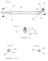
Figur 3- einen einzelnen Zinkentragarm vergrößert
Figur 4- zeigt eine Ansicht nach Pfeil B der
Figur 3 - Figur 5
- zeigt einen Schnitt A - A der
Figur 3 - Figur 6
- zeigt einen Schnitt durch einen weiter nicht dargestellten, mit Zinken versehenen Zinkenträger
- Figure 1
- shows a gyroscope body for a rotary swather in a view from the side, partially cut
- Figure 2
- shows the same object from above in a schematic representation,
- Figure 3
- enlarged a single tine arm
- Figure 4
- shows a view according to arrow B of Figure 3
- Figure 5
- shows a section A - A of Figure 3
- Figure 6
- shows a section through a tine carrier not shown, provided with tines
Eine hohle, etwa senkrecht stehende Säule (1) ist im Zentrum eines Kreiselkörpers vorgesehen. Im oberen Bereich der Säule (1) ist ein Getriebegehäuse (2) fest mit ihr verbunden. In dem Getriebegehäuse (2) ist eine Kegelritzelwelle (3) mit etwa horizontaler Achse drehbar gelagert. Über den das Getriebegehäuse (2) überragenden Achsstummel (4) erfolgt der Antrieb des Kreiselkörpers. Auf einem Kugellager (5), dessen Innenring fest mit der Säule 1 verbunden ist, ist ein mit der Kegelritzelwelle (3) kämmendes Kegelrad (6) drehbar gelagert.A hollow, approximately vertical column (1) is provided in the center of a gyro body. In the upper area of the column (1), a gear housing (2) is firmly connected to it. A bevel pinion shaft (3) with an approximately horizontal axis is rotatably mounted in the gear housing (2). The gyro body is driven via the stub shaft (4) projecting above the gearbox housing (2). A bevel gear (6) which meshes with the bevel pinion shaft (3) is rotatably mounted on a ball bearing (5), the inner ring of which is firmly connected to the column 1.
Im unteren Bereich der Säule (1) ist eine Hülse (7) über diese gestülpt, und mit ihr fest verbunden. Die Hülse (7) ist mit einem Gestellrahmen (8) fest verbunden. Um einen Gelenkbolzen (9) am Gestellrahmen (8) ist ein Radträger (10) schwingbar gelagert. Der Radträger (10) trägt an seinem freien Ende ein Laufrad (11). Die hohle Säule (1) wird von einer Schraubspindel (12) durchsetzt, mit deren Hilfe der Radträger (10) in der Höhe verstellt werden kann. Im oberen Bereich der Hülse (7) ist eine Nabe (13) in Achsrichtung unbeweglich, aber drehbeweglich gelagert. Die Drehbewegung kann durch einen Stellhebel (14) eingeleitet und festgelegt werden. Mit der Nabe (13) ist eine Steuerkurve (15) fest verbunden. Weiterhin ist auf der Nabe (13) ein Kugellager (16) gelagert, dessen Außenring von einer Gehäuseglocke (17) umschlossen wird.In the lower area of the column (1), a sleeve (7) is placed over it and firmly connected to it. The sleeve (7) is firmly connected to a frame (8). A wheel carrier (10) is mounted such that it can swing about a hinge pin (9) on the frame (8). The wheel carrier (10) carries an impeller (11) at its free end. The hollow column (1) is penetrated by a screw spindle (12), with the aid of which the height of the wheel carrier (10) can be adjusted. In the upper area of the sleeve (7), a hub (13) is immovably but rotatably mounted in the axial direction. The rotary movement can be initiated and fixed by an adjusting lever (14). A control cam (15) is firmly connected to the hub (13). Farther a ball bearing (16) is mounted on the hub (13), the outer ring of which is enclosed by a bell housing (17).
Zwei spiegelsymmetrische Gehäuseteile (18) und (19) sind mit Bohrungen (20) einerseits zu dem Kegelrad (6) und andererseits zu der Gehäuseglocke (17) zentriert und durch Verschraubung bzw. Verschweißung fest mit diesen Teilen verbunden. Die Gehäuseteile (18) (19) haben einander zugewandte Planflächen (21) mit Schraublöchern, die von Schrauben (22) durchsetzt werden, wodurch beide Gehäuseteile (18) (19) fest und dicht miteinander verbunden werden. Im Bereich ihres Außendurchmessers haben die Gehäuseteile (18) (19) halbzylinderförmige Ausstülpungen (23), deren Achsen einen gedachten Kreis tangieren, der zwischen dem Zentrum des Kreiselkörpers und dem Außendurchmesser der Gehäuseteile (18) (19) verläuft. In den Austülpungen (23) ist eine Querbohrung (24) vorgesehen. In je ein paar Ausstülpungen (23) können etwa hohlzylinderförmige, vorzugsweise aus Kunststoff gespritzte äußere Traglager (25) eingelegt werden. Diese haben radialgestellte zylindrische Ansätze (26), die in die Querbohrungen (24) eindringen. Die äußeren Traglager (25) werden dadurch in axialer Richtung festgehalten. Im inneren Bereich der Gehäuseteile (18) (19) sind innere Traglager (27) vorgesehen, die fest mit den Gehäuseteilen (18) (19) verschraubt werden und diese dadurch weiter versteifen. Die Bohrungen der äußeren und der inneren Traglager (25) und (27) fluchten.Two mirror-symmetrical housing parts (18) and (19) are centered with bores (20) on the one hand to the bevel gear (6) and on the other hand to the housing bell (17) and firmly connected to these parts by screwing or welding. The housing parts (18) (19) have facing flat surfaces (21) with screw holes through which screws (22) pass, whereby the two housing parts (18) (19) are firmly and tightly connected to each other. In the area of their outer diameter, the housing parts (18) (19) have semi-cylindrical protuberances (23), the axes of which touch an imaginary circle that runs between the center of the gyro body and the outer diameter of the housing parts (18) (19). A transverse bore (24) is provided in the protuberances (23). Hollow-cylindrical outer support bearings (25), preferably molded from plastic, can be inserted into a few protuberances (23). These have radial lugs (26) which penetrate into the transverse bores (24). The outer support bearings (25) are thereby held in the axial direction. In the inner area of the housing parts (18) (19) there are inner support bearings (27) which are screwed tightly to the housing parts (18) (19) and thereby further stiffen them. The holes in the outer and inner support bearings (25) and (27) are aligned.
Aus zylindrischen Rohren hergestellte Zinkentragarme (28) durchsetzen die äußeren und inneren Traglager (25) (27). Ihre inneren Enden sind plastisch derart verformt, daß sie Kurbelwangen (29) bilden. Mit den Kurbelwangen (29) ist ein Lagerbolzen (30) fest verbunden. Auf diesem ist mittels eines Kugellagers (31) eine Steuerrolle (32) drehbar gelagert. In der Nähe der Kurbelwange (29) ist eine Scheibe (33) fest oder lösbar befestigt. Diese Scheibe (33) legt sich gegen eine Stirnfläche eines inneren Traglagers (27) an und kann so axiale Kräfte auf dieses übertragen. Die Steuerrolle (32) läuft in einer C-förmig gestalteten Laufbahn der Steuerkurve (15).Tine support arms (28) made from cylindrical tubes penetrate the outer and inner support bearings (25) (27). Their inner ends are plastically deformed so that they form crank cheeks (29). A bearing pin (30) is firmly connected to the crank webs (29). A control roller (32) is rotatably mounted on this by means of a ball bearing (31). In the vicinity of the crank arm (29), a disc (33) is fixedly or releasably attached. This disc (33) lies against an end face of an inner support bearing (27) and can thus transmit axial forces to it. The steering roller (32) runs in a C-shaped track of the control cam (15).
An ihrem freien Ende sind die Zinkentragarme (28) im Durchmesser etwas eingezogen, damit sie leichter montiert werden können. Außerdem sind sie auf die Länge des eingezogenen Durchmessers mit längs eingepreßten Vertiefungen (34) versehen, die den Innendurchmesser derart verkleinern, daß dort Schrägflächen (35) entstehen, die als Drehmitnehmer dienen können. Die Zinkentragarme (28) sind außerdem im Bereich ihres eingezogenen Durchmessers mit einer Querbohrung (36) versehen.At their free end, the tine support arms (28) are slightly retracted in diameter so that they can be assembled more easily. In addition, they are provided on the length of the retracted diameter with longitudinally pressed-in depressions (34) which reduce the inside diameter in such a way that inclined surfaces (35) are formed there, which can serve as rotary drivers. The tine support arms (28) are also provided with a transverse bore (36) in the area of their retracted diameter.
Mit nicht dargestellten Rechzinken bestückte Zinkenträger (37) (Figur 6) besitzen hohlkehlenförmige, längsgerichtete Vertiefungen (38), die in ihrer Form mit den Schrägflächen (35) der Zinkentragarme (28) korrespondieren. Die Zinkenträger (37) besitzen ebenso wie die Zinkentragarme (28) Querbohrungen (39) und können dadurch mittels Schrauben oder Federsteckern miteinander drehfest und axial gesichert verbunden werden.Tine carriers (37) (FIG. 6) equipped with rake tines (not shown) have flute-shaped, longitudinal recesses (38) which correspond in shape to the inclined surfaces (35) of the tine support arms (28). Like the tine support arms (28), the tine carriers (37) have transverse bores (39) and can therefore be connected to one another in a rotationally fixed and axially secured manner by means of screws or spring plugs.
Claims (18)
- A rotor for hay making machines, in particular for rotary windrowers, comprising support arms (28) which rotate about a substantially perpendicular axis (1) and which are provided with tines and which are rotatably mounted within a closed two-part housing (18, 19) in support bearings (25, 27) associated with both housing portions (18, 19) and which are controlled by means of a control cam (15), characterised in that the two housing portions (18, 19) are fixedly connected together in a planar surface (21) which passes through the central plane of the support bearings (25, 27).
- A rotor according to claim 1 characterised in that the two housing portions (18, 19) are of mirror-image symmetrical configuration.
- A rotor according to claim 1 or claim 2 characterised in that the planar surfaces (21) of the housing portions (18, 19) have protuberances (23) into which outer support bearings (25) can be fitted.
- A rotor according to claim 3 characterised in that the protuberances (23) in the housing portions (18, 19) are of a semicylindrical shape.
- A rotor for hay making machines, in particular for rotary windrowers, comprising support arms (28) which rotate about a substantially perpendicular axis (1) and which are provided with tines and which are rotatably mounted within a closed two-part housing (18, 19) in support bearings (25, 27) associated with both housing portions (18, 19) and which are controlled by means of a control cam (15), characterised in that the two housing portions (18, 19) are fixedly connected together by way of planar surfaces (21) which are in contact with each other, wherein the planar surfaces (21) of the housing portions (18, 19) have protuberances (23) into which outer support bearings (25) can be fitted.
- A rotor according to claims 1 to 5 characterised in that further inner support bearings (27) which are moved more towards the central axis are arranged within the housing portions (18, 19).
- A rotor according to claim 6 characterised in that the inner support bearings (27) are fixedly connected to at least one housing portion (18) or (19) but preferably both housing portions (18, 19).
- A rotor according to claims 3 to 5 characterised in that the outer support bearings (25) have radially directed cylindrical projections (26) which positively lockingly engage into bores (24) in the protuberances (23) of the housing portions (18, 19).
- A rotor according to claims 6 and 7 characterised in that the inner support bearings (27) have radially directed cylindrical projections which positively lockingly engage into bores in the peripheral surfaces of the housing portions (18, 19).
- A rotor according to claims 3 to 9 characterised in that the support bearings (25, 27) comprise plastics mouldings.
- A rotor according to claim 10 characterised in that the support bearings (25, 27) are provided with sealing lips which are injection-moulded thereon and which provide for a sealing action relative to the housing portions (18, 19).
- A rotor according to claim 9 characterised in that the cylindrical projections on the inner support bearings (27) are in the form of metal portions which are inserted into the inner support bearings (27).
- A rotor according to claims 1 to 12 characterised in that the upper housing portion (18) is directly fixedly connected to the driving bevel wheel (6).
- A rotor according to claims 1 to 13 characterised in that the lower housing portion (19) is fixedly connected to a housing bell (17) which accomodates a ball bearing (16).
- A rotor according to claims 1 to 14 characterised in that the tine support arms (28) each pass through an outer and an inner support bearing (25) and (27) respectively.
- A rotor according to claim 15 characterised in that the tine support arms (28) comprise cylindrical tubes whose ends which are towards the centre of the rotors are plastically deformed in such a way that they form crank webs (29) which in turn are fixedly connected to mounting pins (30) for control rollers (32).
- A rotor according to claim 15 characterised in that the tine support arms (28) comprise cylindrical tubes which at their ends remote from the rotor are plastically deformed in such a way as to provide entrainment surfaces (35) directed towards their central axis.
- A rotor according to claim 17 characterised in that tine carriers (37) can be inserted into the ends of the tine support arms (28), which are remote from the rotor, which tine carriers have at their periphery grooves (38) which together with the entrainment surfaces (35) of the tine support arms (28) represent a non-rotatable connection.
Applications Claiming Priority (2)
| Application Number | Priority Date | Filing Date | Title |
|---|---|---|---|
| DE4232768A DE4232768A1 (en) | 1992-09-30 | 1992-09-30 | Rotary bodies for hay machines, in particular for rotary swathers |
| DE4232768 | 1992-09-30 |
Publications (2)
| Publication Number | Publication Date |
|---|---|
| EP0590311A1 EP0590311A1 (en) | 1994-04-06 |
| EP0590311B1 true EP0590311B1 (en) | 1997-06-11 |
Family
ID=6469227
Family Applications (1)
| Application Number | Title | Priority Date | Filing Date |
|---|---|---|---|
| EP93113626A Expired - Lifetime EP0590311B1 (en) | 1992-09-30 | 1993-08-26 | Rake wheel for haymaking machine especially for windrower |
Country Status (5)
| Country | Link |
|---|---|
| EP (1) | EP0590311B1 (en) |
| AT (1) | ATE154191T1 (en) |
| CZ (1) | CZ285700B6 (en) |
| DE (2) | DE4232768A1 (en) |
| HU (1) | HU216768B (en) |
Cited By (1)
| Publication number | Priority date | Publication date | Assignee | Title |
|---|---|---|---|---|
| DE19746216B4 (en) * | 1997-10-21 | 2004-11-18 | Maschinenfabrik Bernard Krone Gmbh | Rotary rake for a haymaking machine |
Families Citing this family (8)
| Publication number | Priority date | Publication date | Assignee | Title |
|---|---|---|---|---|
| DE19502710C1 (en) * | 1995-01-28 | 1996-08-22 | Krone Bernhard Gmbh Maschf | Rotary rake for a haymaking machine |
| DE29515382U1 (en) * | 1995-09-26 | 1996-01-25 | Greenland Gmbh & Co Kg | Agricultural machine |
| DE19650650C2 (en) * | 1996-12-06 | 1999-07-22 | Krone Bernhard Gmbh Maschf | Rotary rake for a haymaking machine |
| ITVI980098A1 (en) * | 1998-05-11 | 1999-11-11 | Meccaniche Bertuzzo Srl Costru | PHASE VARIATOR, PARTICULARLY FOR ROTARY OSCILLATOR REDUCER |
| FR2842067B1 (en) * | 2002-07-15 | 2005-02-04 | Kuhn Sa | FEEDING MACHINE WITH AT LEAST ONE PERFECTED ROTOR |
| FR2842068B1 (en) | 2002-07-15 | 2005-01-07 | Kuhn Sa | A ROTOR WITH AN IMPROVED CONNECTION BETWEEN WORKING TOOLS AND THE CARTER |
| EP1803344B1 (en) | 2004-07-28 | 2009-09-30 | Claas Saulgau Gmbh | Rotary swather for a hay-making machine |
| NL1036168C2 (en) * | 2008-11-07 | 2010-05-10 | Lely Patent Nv | SHARED RAKE ARM WITH QUICK COUPLING. |
Family Cites Families (11)
| Publication number | Priority date | Publication date | Assignee | Title |
|---|---|---|---|---|
| CH450793A (en) * | 1967-06-19 | 1968-01-31 | Bucher Guyer Ag Masch | Haymaking machine |
| CH493186A (en) * | 1968-07-04 | 1970-07-15 | Bucher Guyer Ag Masch | Haymaking machine |
| CH499951A (en) * | 1968-12-06 | 1970-12-15 | Bucher Guyer Ag Masch | Haymaking machine |
| BE757910A (en) * | 1969-10-30 | 1971-04-01 | Fahr Ag Maschf | RAKING WHEEL FOR HAYING MACHINES |
| FR2380718A1 (en) * | 1977-02-18 | 1978-09-15 | Kuhn Sa | Haymaking machine designed in particular for swathing fodder |
| FR2450554B1 (en) * | 1979-03-09 | 1985-07-05 | Belrecolt Sa | IMPROVEMENT IN COMBINED HAYMAKING MACHINES |
| SE449417B (en) * | 1979-05-02 | 1987-05-04 | Bucher Guyer Ag Masch | OBJECTIVE MACHINE AS WELL AS ASTADCOMMING DIFFERENT UNUSED MORALS OF THE REFLECTORS AT A OBJECTIVE |
| DE3324094A1 (en) * | 1983-07-05 | 1985-01-17 | Wilhelm Stoll Maschinenfabrik Gmbh, 3325 Lengede | HAY ADVERTISING MACHINE |
| FR2632155B1 (en) * | 1988-06-03 | 1991-10-11 | Kuhn Sa | FENAISON MACHINE HAVING A ROTOR FOR RAKING |
| DE4036685A1 (en) * | 1990-11-17 | 1992-05-21 | Poettinger Alois Landmasch | Rotary swather unit - has revolving rake wheel to which are attached revolving tine bearing arms in holers |
| DE4201881A1 (en) * | 1992-01-24 | 1993-07-29 | Krone Bernhard Gmbh Maschf | Rotary swather with rotary rakes following curved track - has changeable position of curved track through rotation about rotary axis of rake |
-
1992
- 1992-09-30 DE DE4232768A patent/DE4232768A1/en not_active Withdrawn
-
1993
- 1993-08-26 DE DE59306725T patent/DE59306725D1/en not_active Expired - Fee Related
- 1993-08-26 EP EP93113626A patent/EP0590311B1/en not_active Expired - Lifetime
- 1993-08-26 AT AT93113626T patent/ATE154191T1/en not_active IP Right Cessation
- 1993-09-01 HU HU9302469A patent/HU216768B/en not_active IP Right Cessation
- 1993-09-24 CZ CZ931987A patent/CZ285700B6/en not_active IP Right Cessation
Cited By (1)
| Publication number | Priority date | Publication date | Assignee | Title |
|---|---|---|---|---|
| DE19746216B4 (en) * | 1997-10-21 | 2004-11-18 | Maschinenfabrik Bernard Krone Gmbh | Rotary rake for a haymaking machine |
Also Published As
| Publication number | Publication date |
|---|---|
| DE4232768A1 (en) | 1994-03-31 |
| CZ285700B6 (en) | 1999-10-13 |
| EP0590311A1 (en) | 1994-04-06 |
| ATE154191T1 (en) | 1997-06-15 |
| HU9302469D0 (en) | 1993-11-29 |
| DE59306725D1 (en) | 1997-07-17 |
| CZ198793A3 (en) | 1994-04-13 |
| HU216768B (en) | 1999-08-30 |
| HUT69880A (en) | 1995-09-28 |
Similar Documents
| Publication | Publication Date | Title |
|---|---|---|
| DE3153605C2 (en) | ||
| EP0590311B1 (en) | Rake wheel for haymaking machine especially for windrower | |
| DE3903676C2 (en) | ||
| EP2177801B1 (en) | Actuating device, in particular for actuating a waste gas return valve | |
| DE3636194C1 (en) | Homokinetic double joint | |
| DE2804339A1 (en) | PROTECTIVE SEAL FOR JOINT CONNECTIONS OF MOTOR VEHICLE SHAFTS | |
| DE3522700C2 (en) | ||
| DE4305581A1 (en) | Rotor for a swivel cup centrifuge | |
| DE69819826T2 (en) | POWER CONTROL SYSTEM | |
| EP0949419B1 (en) | Internal gear pump | |
| EP0723741B1 (en) | Rotary rake for a hay making machine | |
| DD202597A5 (en) | MECHANISM FOR THE CONVERSION OF A TURNING MOVEMENT IN A STRAIGHT-LOOKING MOVEMENT | |
| DE4427410C5 (en) | Exterior rearview mirror for motor vehicles | |
| DE2921421C2 (en) | Rotor for a rotary wing aircraft with at least two hub plates | |
| WO1997016332A1 (en) | Drive device for at least two vehicle windscreen wipers | |
| DE4102515C2 (en) | ||
| DE3026799C2 (en) | Gear for seat adjustment | |
| EP1431604A1 (en) | Universal joint with retainer element. | |
| EP0068477B1 (en) | Support link or another link in the form of a tube, especially for agricultural machines | |
| EP3812601B1 (en) | Shaped part, securing device with the shaped part, agricultural work machine with the securing device and method for mounting the securing device | |
| EP0533657B1 (en) | Steering gear, in particular for motor vehicles | |
| DE3120552A1 (en) | Pedal cycle | |
| DE2300079C2 (en) | Support roller for a roller conveyor | |
| EP0846410B1 (en) | Rotary rake for haymaking machine | |
| DE2055841B2 (en) | Sweeping machine, especially with a hand drive |
Legal Events
| Date | Code | Title | Description |
|---|---|---|---|
| PUAI | Public reference made under article 153(3) epc to a published international application that has entered the european phase |
Free format text: ORIGINAL CODE: 0009012 |
|
| AK | Designated contracting states |
Kind code of ref document: A1 Designated state(s): AT CH DE FR GB IT LI NL SE |
|
| 17P | Request for examination filed |
Effective date: 19940826 |
|
| 17Q | First examination report despatched |
Effective date: 19951219 |
|
| GRAG | Despatch of communication of intention to grant |
Free format text: ORIGINAL CODE: EPIDOS AGRA |
|
| GRAH | Despatch of communication of intention to grant a patent |
Free format text: ORIGINAL CODE: EPIDOS IGRA |
|
| GRAH | Despatch of communication of intention to grant a patent |
Free format text: ORIGINAL CODE: EPIDOS IGRA |
|
| GRAA | (expected) grant |
Free format text: ORIGINAL CODE: 0009210 |
|
| STAA | Information on the status of an ep patent application or granted ep patent |
Free format text: STATUS: THE PATENT HAS BEEN GRANTED |
|
| AK | Designated contracting states |
Kind code of ref document: B1 Designated state(s): AT CH DE FR GB IT LI NL SE |
|
| REF | Corresponds to: |
Ref document number: 154191 Country of ref document: AT Date of ref document: 19970615 Kind code of ref document: T |
|
| REG | Reference to a national code |
Ref country code: CH Ref legal event code: EP |
|
| REG | Reference to a national code |
Ref country code: CH Ref legal event code: NV Representative=s name: TROESCH SCHEIDEGGER WERNER AG |
|
| REF | Corresponds to: |
Ref document number: 59306725 Country of ref document: DE Date of ref document: 19970717 |
|
| GBT | Gb: translation of ep patent filed (gb section 77(6)(a)/1977) |
Effective date: 19970704 |
|
| ET | Fr: translation filed | ||
| PLBE | No opposition filed within time limit |
Free format text: ORIGINAL CODE: 0009261 |
|
| 26N | No opposition filed | ||
| REG | Reference to a national code |
Ref country code: FR Ref legal event code: ST |
|
| REG | Reference to a national code |
Ref country code: FR Ref legal event code: RN |
|
| REG | Reference to a national code |
Ref country code: FR Ref legal event code: FC Free format text: BO 99/29, PAGES: 282, IL Y A LIEU D'AJOUTER: LE BREVET 0590311 |
|
| REG | Reference to a national code |
Ref country code: GB Ref legal event code: IF02 |
|
| PGFP | Annual fee paid to national office [announced via postgrant information from national office to epo] |
Ref country code: GB Payment date: 20020805 Year of fee payment: 10 |
|
| PGFP | Annual fee paid to national office [announced via postgrant information from national office to epo] |
Ref country code: CH Payment date: 20020821 Year of fee payment: 10 |
|
| PGFP | Annual fee paid to national office [announced via postgrant information from national office to epo] |
Ref country code: SE Payment date: 20020822 Year of fee payment: 10 |
|
| PGFP | Annual fee paid to national office [announced via postgrant information from national office to epo] |
Ref country code: AT Payment date: 20030825 Year of fee payment: 11 |
|
| PG25 | Lapsed in a contracting state [announced via postgrant information from national office to epo] |
Ref country code: GB Free format text: LAPSE BECAUSE OF NON-PAYMENT OF DUE FEES Effective date: 20030826 |
|
| PG25 | Lapsed in a contracting state [announced via postgrant information from national office to epo] |
Ref country code: SE Free format text: LAPSE BECAUSE OF NON-PAYMENT OF DUE FEES Effective date: 20030827 |
|
| PGFP | Annual fee paid to national office [announced via postgrant information from national office to epo] |
Ref country code: NL Payment date: 20030828 Year of fee payment: 11 |
|
| PG25 | Lapsed in a contracting state [announced via postgrant information from national office to epo] |
Ref country code: LI Free format text: LAPSE BECAUSE OF NON-PAYMENT OF DUE FEES Effective date: 20030831 Ref country code: CH Free format text: LAPSE BECAUSE OF NON-PAYMENT OF DUE FEES Effective date: 20030831 |
|
| EUG | Se: european patent has lapsed | ||
| GBPC | Gb: european patent ceased through non-payment of renewal fee | ||
| REG | Reference to a national code |
Ref country code: CH Ref legal event code: PL |
|
| PG25 | Lapsed in a contracting state [announced via postgrant information from national office to epo] |
Ref country code: AT Free format text: LAPSE BECAUSE OF NON-PAYMENT OF DUE FEES Effective date: 20040826 |
|
| PG25 | Lapsed in a contracting state [announced via postgrant information from national office to epo] |
Ref country code: NL Free format text: LAPSE BECAUSE OF NON-PAYMENT OF DUE FEES Effective date: 20050301 |
|
| NLV4 | Nl: lapsed or anulled due to non-payment of the annual fee |
Effective date: 20050301 |
|
| PG25 | Lapsed in a contracting state [announced via postgrant information from national office to epo] |
Ref country code: IT Free format text: LAPSE BECAUSE OF NON-PAYMENT OF DUE FEES Effective date: 20050826 |
|
| PGFP | Annual fee paid to national office [announced via postgrant information from national office to epo] |
Ref country code: DE Payment date: 20060912 Year of fee payment: 15 |
|
| PGFP | Annual fee paid to national office [announced via postgrant information from national office to epo] |
Ref country code: FR Payment date: 20080314 Year of fee payment: 16 |
|
| REG | Reference to a national code |
Ref country code: FR Ref legal event code: ST Effective date: 20090430 |
|
| PG25 | Lapsed in a contracting state [announced via postgrant information from national office to epo] |
Ref country code: FR Free format text: LAPSE BECAUSE OF NON-PAYMENT OF DUE FEES Effective date: 20080901 Ref country code: DE Free format text: LAPSE BECAUSE OF NON-PAYMENT OF DUE FEES Effective date: 20090303 |