EP0590298B1 - Synchronisation procedure of a receiver for the reception of a data signal spread by a PN-code - Google Patents
Synchronisation procedure of a receiver for the reception of a data signal spread by a PN-code Download PDFInfo
- Publication number
- EP0590298B1 EP0590298B1 EP93113446A EP93113446A EP0590298B1 EP 0590298 B1 EP0590298 B1 EP 0590298B1 EP 93113446 A EP93113446 A EP 93113446A EP 93113446 A EP93113446 A EP 93113446A EP 0590298 B1 EP0590298 B1 EP 0590298B1
- Authority
- EP
- European Patent Office
- Prior art keywords
- code
- signal
- correlation
- signals
- phase
- Prior art date
- Legal status (The legal status is an assumption and is not a legal conclusion. Google has not performed a legal analysis and makes no representation as to the accuracy of the status listed.)
- Expired - Lifetime
Links
- 238000000034 method Methods 0.000 title claims description 18
- 230000002596 correlated effect Effects 0.000 claims description 7
- 239000011159 matrix material Substances 0.000 claims description 7
- 230000003044 adaptive effect Effects 0.000 claims 1
- 238000001228 spectrum Methods 0.000 claims 1
- 238000010586 diagram Methods 0.000 description 6
- 230000000875 corresponding effect Effects 0.000 description 4
- 230000000737 periodic effect Effects 0.000 description 3
- 230000010363 phase shift Effects 0.000 description 3
- 230000003111 delayed effect Effects 0.000 description 2
- 238000005259 measurement Methods 0.000 description 2
- 230000002123 temporal effect Effects 0.000 description 2
- 230000001133 acceleration Effects 0.000 description 1
- 230000005540 biological transmission Effects 0.000 description 1
- 239000000969 carrier Substances 0.000 description 1
- 230000001413 cellular effect Effects 0.000 description 1
- 230000001419 dependent effect Effects 0.000 description 1
- 238000012544 monitoring process Methods 0.000 description 1
- 230000002441 reversible effect Effects 0.000 description 1
- 230000003595 spectral effect Effects 0.000 description 1
Images


Classifications
-
- H—ELECTRICITY
- H04—ELECTRIC COMMUNICATION TECHNIQUE
- H04B—TRANSMISSION
- H04B1/00—Details of transmission systems, not covered by a single one of groups H04B3/00 - H04B13/00; Details of transmission systems not characterised by the medium used for transmission
- H04B1/69—Spread spectrum techniques
- H04B1/707—Spread spectrum techniques using direct sequence modulation
- H04B1/7073—Synchronisation aspects
- H04B1/7085—Synchronisation aspects using a code tracking loop, e.g. a delay-locked loop
Definitions
- the invention relates to a method for synchronization a receiver circuit for a received signal, which contains a data signal spread with a PN code, in which on the basis of an adjustable timer at least three PN code signals offset in time be generated, with a medium PN code signal with the received signal for data demodulation and a leading and trailing PN code signal for control purposes of the timer can be correlated with the received signal.
- PN "pseudo noise”
- the bandwidth of the PN signal is much larger than that of the message signal, the latter is spectrally spread. This requires considerable effort on the receiver side to synchronize the PN code in order to undo the spectral broadening.
- the PN code (receiver code) generated locally in the receiver must match the PN code of the received signal (transmitter code) more precisely than 1 code chip (duration T c ).
- the receiver synchronization is carried out by two process stages connected in series, namely the coarse synchronization ("acquisition") and the fine synchronization ("tracking").
- Such non-linear control loops have the property that they can lose synchronism under interference (Disengaging phenomenon).
- One way to snap this out prevent or increase the time until it disengages consists in the broadening of usually two correlation signals formed discriminator characteristic (Control characteristic, also called S-curve) with the help of additional ones Correlators.
- Control characteristic also called S-curve
- additional ones Correlators So z. B. from DE 37 43 731 Fine synchronization method with widened discriminator characteristic known. For this purpose, many are out of phase Code signals generated, all with the incoming Data signal are correlated. From the resulting Correlation curves become a by appropriate weighting Characteristic curve generated with an enlarged linear range. Because of of the additional correlators takes place in the synchronization circuit but the influence of channel noise while the useful signal contributions remain the same. In addition, the Greater effort for realization.
- the object of the invention is a method of the aforementioned Specify a type that improves synchronization behavior, especially tracking in a large one Control range allowed.
- the solution is that with one temporal drift of the data signal forward respectively. backwards on through the leading and trailing PN code signal defined control range adaptively shifted is by the trailing resp. the leading PN code signal by a predetermined time interval to the front resp. is moved to the rearmost position and reassigned the PN code sequences the data signal for data demodulation correlated with the PN code signal, which is now temporally mean becomes.
- the core of a PN code tracking loop according to the invention is that with increasing synchronization errors (Drift) individual correlation arms switched, d. H. on a different code position will be moved. This creates a periodic and piecewise linear discriminator characteristic.
- the advantage over the classic control loops e.g. DLL
- a narrow band control loop with a low-order loop filter in principle fast dynamic processes by switching individual correlation arms can readjust.
- a narrow-band classic tracking loop with the same Loop filter not a fast changing input signal can follow and bass out.
- Correlators necessary.
- exactly three PN code signals offset by deltaT c are generated.
- the previous resp. later PN code signal by 3 deltaT c to the front resp. last position moved is covered with only three correlators.
- the switching criterion is advantageously chosen such that there is always a switching hysteresis. This makes an all too frequent switching avoided. It will also be an advantage paid attention to the performance of the correlation signal in the data path (i.e. in the path that is used for data demodulation a certain percentage (related to the maximum possible correlation performance).
- a Moving the control range whenever the performance of the correlation signal in the correlation path is smaller than that Is half that of a rule path. This can help the advantageous switching hysteresis can be achieved in a simple manner.
- a synchronization circuit is a switching matrix with which optionally two adaptively definable signal paths to the control circuit and one passed to a data modulation circuit can be.
- the PN code generator is designed that the phase position of each PN code signal output at the outputs can be shifted in phase by predetermined intervals is. This can be done e.g. B. with controllable resp. implement programmable delay elements.
- the inventive method is particularly suitable for Synchronize cellular receivers. With these shifts the received signal depends on the relative speed towards the broadcaster.
- a received signal r (t) to three essentially identical in terms of circuitry Correlation paths split.
- the received signal r (t) with a PN code signal correlated defined phase position.
- Bandpass filter 2.1 respectively 2.2 resp. 2.3 becomes the output signal the mixer 1.1 respectively.
- 1.2 resp. 1.3 in itself filtered in a known manner and then on the one hand via a line 4.1 resp. 4.2 resp. 4.3 direct synchronization control 5 and on the other hand an envelope detector 3.1 resp. 3.2 resp. 3.3 fed.
- the envelope detectors 3.1, 3.2, 3.3 form z. B. the absolute amount of the input signal or the amplitude square.
- the one with the envelope detectors 3.1, 3.2, 3.3 generated data-neutral correlation signals are also fed to the synchronization controller 5.
- the synchronization controller 5 represents the heart of the switching arrangement according to the invention. It outputs an (despread) signal for data demodulation at an output 6, from which the transmitted data are extracted by means of a demodulation circuit (not shown). An error signal e (t) is output at an output 7 and is fed to a VCO 9 via a circular filter 8.
- This VCO 9 represents the timer for a PN code generator 10 which, according to the invention, can generate identical PN code signals at three outputs 11.1, 11.2, 11.3 except for the phase position.
- the phase position of each PN code signal can be varied within a predetermined time grid.
- the time grid is defined by a time difference deltaT c .
- the synchronization controller 5 also gives the circular filter 8 the important in the switching described below Initial conditions. Finally, it gives to the PN code generator 10 the code positions respectively. Phases for the PN signals continue.
- Hint is one for any heterodyne The necessary expansion of the circuit is drawn in. It is a local oscillator 12 and a multiplier / mixer 13.1, 13.2, 13.3 for each PN code signals output at outputs 11.1, 11.2, 11.3.
- the functioning of the synchronization controller 5 will be explained with reference to FIGS. 2a-e. It is assumed that three PN code signals are shifted at the outputs 11.1, 11.2, 11.3 by deltaT c in time.
- the (phase-wise) mean PN code signal which e.g. B. at the output 11.2 and correlated in the mixer 1.2 with the received signal r (t), in particular the controllable timer (VCO 9) tracks the received signal r (t) as well as possible by means of the synchronization circuit.
- a characteristic curve 17.1 is obtained, which in principle allows a control range of width 2 (T c + deltaT c ) (characteristic curve 17.1 disappears outside this range).
- the error signal for tracking the VCO 9 has an amplitude which follows from the characteristic curve 17.1 in accordance with the synchronization error epsilon.
- the data demodulation is carried out on the basis of the middle correlation curve 15. Under normal circumstances, ie when there is no drift in the phase position of the received signal, the synchronization circuit according to the invention operates on the principle of a conventional DLL. However, if the received signal shifts so much in phase that the power according to correlation curve 15 is lower than in correlation curve 14 or 16, the switchover described below is carried out.
- the correlation paths are reassigned in the sense that the data demodulation is carried out on the basis of the now (phase-wise) mean correlation curve 16.
- the difference between the correlation curve 19 and the formerly mean correlation curve 15 is used to generate the error signal (cf. FIG. 2d).
- a comparison of the two FIGS. 2b and d shows that the time-shifted characteristic curve 17.2 has taken the place of the characteristic curve 17.1.
- the control is now also carried out on another zero point (which is also shifted by deltaT c ).
- the whole switching process described above is from the Synchronization control 5 performed. She tests the Correlation values in the three paths determine the necessary ones
- the individual PN code signals are shifted Initial condition for the output signal of the circular filter 8 and changes the assignment between the over the lines 4.1, 4.2, 4.3 fed correlation signals and the output 6.
- a switchover criterion which is particularly preferred is leads to a hysteresis of the discriminator characteristic.
- An example for a switchover with hysteresis is from Fig. 3c and d. In this example, we always switch over if the performance in the leading or trailing Path is twice the size of the middle one. Because of the smaller distance between the correlation curves 22.1, ..., 22.5 (compared to Fig. 2), the preferred, means Arrows indicated hysteresis in the discriminator characteristic 23. It should be noted that ideally when switching the phase error disappears because the new "rest position" with the "limit point" of the characteristic which has not yet been switched over coincides.
- Hysteresis can be done with a variety of means bring about. So z. B. also more than three correlation paths are provided, with a switching by Monitoring the signal power in the different correlation paths and switching the path of maximum power be improved for data demodulation. At four or five parallel correlation paths is not just one middle path available and a switch respectively. Move the control range can be postponed longer, without the performance in the demodulation path being too small becomes. For example, there are five correlation paths three middle paths, optionally based on the maximum criterion Performance can be used for data demodulation can. As long as the received signal is not in the range of earliest resp. latest correlation signal runs in namely, no phase shifts are required.
- Fig. 4 shows a block diagram of the synchronization control 5.
- a switching matrix 24 is designed so that of control signals of the changeover control 29 optionally one of the adjoining inputs 26.1, 26.2, 26.3 Signals containing data on the output 27.1 purpose Data demodulation can be switched.
- the envelopes of the Signals are sent to inputs 30.1, 30.2, 30.3 of the switchover control 29 fed. This leads with the aid of FIGS. 2a-e and 3a-d explained tests and determined the reallocation the correlation paths, the initial conditions for the Circular filter 8 (output 32) and the code position resp. Phase position for the PN code generator 10 (output 31).
- the switching matrix 24 also has inputs 25.1, 25.2, 25.3 for the data-neutral output signals of the envelope detectors 3.1, 3.2, 3.3 (see Fig. 1). Two of these three entrances are in accordance with the control signals of the switching control 29 given to outputs 27.2 and 27.3. A subtractor 28 forms the difference and gives it as an error signal (Input signal of the circular filter 8).
- FIG. 5 finally shows a block diagram of a synchronization control for synchronization according to the principle of the MCTL (Modified Code Tracking Loop).
- a switching matrix 33 At the entrances 34.1, 34.2, 34.3 of a switching matrix 33 are the data carriers Correlation signals (see lines 4.1, 4.2, 4.3 in Fig. 1).
- the input signals mentioned are corresponding the signals of a switching control 41 optionally the outputs 35, 36, 37 out.
- the output 35 is for the Data demodulation used.
- the outputs 36 and 37 are subtracted from each other in a subtractor 38.
- the resulting one Difference is in a multiplier 39 by multiplied signal output at the output 35. This results at an output 40 the error signal, which via a Circular filter is given to a VCO.
- the invention is also based on other known control structures applicable.
- a structure is e.g. B. the known tau dither loop. Similar to what happens with the DLL in the tau dither loop by the invention a periodic Discriminator characteristic generated. The same applies to the so-called double dither loop.
- the new PN code tracking loop it is thus possible with three shifted and adaptively switchable correlation paths a periodic Generate discriminator characteristic.
- the circuit concept according to the invention can also be used for coarse synchronization and leads to a significant acceleration. Because all three Correlation arms are constructed identically and a performance measurement Coarse synchronization is possible in all arms about three times faster than with a synchronization circuit in which only one correlation path is available for a performance measurement.
Description
Die Erfindung bezieht sich auf ein Verfahren zum Synchronisieren eines Empfängerschaltkreises auf ein Empfangssignal, welches ein mit einem PN-Code gespreiztes Datensignal beinhaltet, bei welchem auf der Basis eines regelbaren Zeitgebers mindestens drei zeitlich gegeneinander versetzte PN-Code-Signale erzeugt werden, wobei ein mittleres PN-Code-Signal mit dem Empfangssignal zwecks Datendemodulation und ein voreilendes und nachlaufendes PN-Code-Signal zwecks Regelung des Zeitgebers mit dem Empfangssignal korreliert werden. The invention relates to a method for synchronization a receiver circuit for a received signal, which contains a data signal spread with a PN code, in which on the basis of an adjustable timer at least three PN code signals offset in time be generated, with a medium PN code signal with the received signal for data demodulation and a leading and trailing PN code signal for control purposes of the timer can be correlated with the received signal.
Beim Einsatz eines Direct-Sequence-Verfahrens zur Uebertragung von Nachrichtensignalen mit Hilfe der Bandspreiztechnik wird ein bereits mit dem Nachrichtensignal modulierter Träger zusätzlich mit einem sogenannten PN-Code (PN = "Pseudo Noise") multipliziert. Da die Bandbreite des PN-Signals viel grösser als diejenige des Nachrichtensignals ist, erfolgt eine spektrale Spreizung des letzteren. Dies bedingt empfängerseitig einen beträchtlichen Aufwand zur Synchronisation des PN-Codes, um die spektrale Verbreiterung wieder rückgängig zu machen. Für die Datendemodulation muss nämlich der lokal im Empfänger erzeugte PN-Code (Empfänger-Code) genauer als 1 Code-Chip (Dauer Tc) mit dem PN-Code des empfangenen Signals (Sender-Code) übereinstimmen. In der Praxis wird die Empfängersynchronisation durch zwei hintereinandergeschaltete Verfahrensstufen, nämlich die Grobsynchronisation ("Acquisition") und die Feinsynchronisation ("Tracking") durchgeführt.When using a direct sequence method for the transmission of message signals with the aid of the spreading technique, a carrier that has already been modulated with the message signal is additionally multiplied by a so-called PN code (PN = "pseudo noise"). Since the bandwidth of the PN signal is much larger than that of the message signal, the latter is spectrally spread. This requires considerable effort on the receiver side to synchronize the PN code in order to undo the spectral broadening. For data demodulation, the PN code (receiver code) generated locally in the receiver must match the PN code of the received signal (transmitter code) more precisely than 1 code chip (duration T c ). In practice, the receiver synchronization is carried out by two process stages connected in series, namely the coarse synchronization ("acquisition") and the fine synchronization ("tracking").
Aus der DE 37 43 732 ist beispielsweise ein derartiges Synchronisationsverfahren bekannt. Zur Grobsynchronisation müssen im Prinzip alle möglichen relativen Code-Verschiebungen ausgetestet werden, bis mittels einer Leistungsmessung die ungefähre zeitliche Uebereinstimmung der beiden Codes festgestellt werden kann. Zur Beschleunigung der Grobsynchronisation wird dabei vorgeschlagen, das Code-Wort wiederholt in jeweils mehreren unterschiedlichen Phasenlagen zu erzeugen, so dass pro Zeiteinheit gleichzeitig mehrere Phasenlagen überprüft werden können. Der Suchvorgang wird beendet, wenn in mindestens einer der unterschiedlichen Phasenlagen eine Korrelation zwischen dem Code-Wort und dem empfangenen Signal festgestellt wird. Die nachfolgende Feinsynchronisation wird mit einem Regelkreis (z. B. einem Delay-Locked-Loop, DLL) durchgeführt. DE 37 43 732 describes such a synchronization method, for example known. For rough synchronization in principle all possible relative code shifts be tested until the Approximate temporal agreement between the two codes was found can be. To accelerate the coarse synchronization it is suggested to repeat the code word in to generate several different phase positions, so that several phase positions per time unit can be checked. The search will stop when in at least one of the different phase positions Correlation between the code word and the received signal is detected. The subsequent fine synchronization is used with a control loop (e.g. a delay-locked loop, DLL).
Solche nichtlinearen Regelkreise haben die Eigenschaft, dass
sie unter Störeinflüssen den Synchronismus verlieren können
(Ausrastphänomen). Eine Möglichkeit, dieses Ausrasten zu
verhindern oder die Zeit bis zum Ausrasten zu vergrössern,
besteht in der Verbreiterung der üblicherweise aus zwei Korrelationssignalen
gebildeten Diskriminatorcharakteristik
(Regelkennlinie, auch S-Kurve genannt) mit Hilfe von zusätzlichen
Korrelatoren. So ist z. B. aus der DE 37 43 731 ein
Feinsynchronisationsverfahren mit verbreiterter Diskriminatorkennlinie
bekannt. Zu diesem Zwecke werden viele phasenverschobene
Code-Signale erzeugt, die alle mit dem eintreffenden
Datensignal korreliert werden. Aus den resultierenden
Korrelationskurven wird durch geeignete Gewichtung eine
Kennlinie mit vergrössertem linearen Bereich erzeugt. Wegen
der zusätzlichen Korrelatoren nimmt in der Synchronisationsschaltung
aber der Einfluss des Kanalrauschens zu, während
die Nutzsignalbeiträge gleich bleiben. Zudem ist auch der
Aufwand für eine Realisierung grösser.Such non-linear control loops have the property that
they can lose synchronism under interference
(Disengaging phenomenon). One way to snap this out
prevent or increase the time until it disengages,
consists in the broadening of usually two correlation signals
formed discriminator characteristic
(Control characteristic, also called S-curve) with the help of additional ones
Correlators. So z. B. from
Aufgabe der Erfindung ist es, ein Verfahren der eingangs genannten Art anzugeben, das ein verbessertes Synchronisationsverhalten, insbesondere ein Nachführen in einem grossen Regelbereich erlaubt.The object of the invention is a method of the aforementioned Specify a type that improves synchronization behavior, especially tracking in a large one Control range allowed.
Gemäss der Erfindung besteht die Lösung darin, dass bei einer zeitlichen Drift des Datensignals nach vorwärts resp. nach rückwärts ein durch das voreilende und das nachlaufende PN-Code-Signal definierter Regelbereich adaptiv verschoben wird, indem das nachlaufende resp. das voreilende PN-Code-Signal um ein vorgegebenes Zeitintervall an vorderste resp. an hinterste Stelle verschoben wird und unter Neuzuordnung der PN-Code-Sequenzen das Datensignal zwecks Datendemodulation mit dem nunmehr zeitlich mittleren PN-Code-Signal korreliert wird.According to the invention, the solution is that with one temporal drift of the data signal forward respectively. backwards on through the leading and trailing PN code signal defined control range adaptively shifted is by the trailing resp. the leading PN code signal by a predetermined time interval to the front resp. is moved to the rearmost position and reassigned the PN code sequences the data signal for data demodulation correlated with the PN code signal, which is now temporally mean becomes.
Der Kern eines erfindungsgemässen PN-Code Tracking-Loops liegt darin, dass bei zunehmendem Synchronisationsfehler (Drift) einzelne Korrelationsarme umgeschaltet, d. h. auf eine andere Code-Position verschoben werden. Dadurch entsteht eine periodische und stückweise lineare Diskriminatorkennlinie. Der Vorteil gegenüber den klassischen Regelkreisen (z. B. DLL) besteht darin, dass ein schmalbandiger Regelkreis mit einem Loop-Filter niedriger Ordnung prinzipiell schnelle dynamische Vorgänge durch Umschalten einzelner Korrelationsarme nachregeln kann. Demgegenüber würde ein schmalbandiger klassischer Tracking-Loop mit dem gleichen Loop-Filter einem schnell ändernden Eingangssignal nicht nachfolgen können und ausrasten. Im Gegensatz zu den aus dem Stand der Technik bekannten Regelkreisen mit verbreiterter Diskriminatorkennlinie sind bei der Erfindung keine weiteren Korrelatoren notwendig. Ein wichtiger Aspekt besteh-t zudem darin, dass mit dem Umschalten des Codes in den Korrelationsarmen auch der Pfad für die Datendemodulation entsprechend neu gesetzt wird.The core of a PN code tracking loop according to the invention is that with increasing synchronization errors (Drift) individual correlation arms switched, d. H. on a different code position will be moved. This creates a periodic and piecewise linear discriminator characteristic. The advantage over the classic control loops (e.g. DLL) is that a narrow band control loop with a low-order loop filter in principle fast dynamic processes by switching individual correlation arms can readjust. In contrast, a narrow-band classic tracking loop with the same Loop filter not a fast changing input signal can follow and freak out. In contrast to those from the State of the art control loops with widened Discriminator characteristics are no further in the invention Correlators necessary. There is also an important aspect in that with switching the code in the correlation arms also the path for data demodulation accordingly is reset.
Gemäss einer bevorzugten Ausführungsform der Erfindung werden genau drei um je deltaTc versetzte PN-Code-Signale erzeugt. Beim adaptiven Verschieben des Regelbereichs wird das frühere resp. spätere PN-Code-Signal um 3 deltaTc an vorderste resp. hinterste Stelle verschoben. Mit nur drei Korrelatoren kann also ein im Prinzip beliebig breiter Regelbereich abgedeckt werden.According to a preferred embodiment of the invention, exactly three PN code signals offset by deltaT c are generated. When adaptively shifting the control range, the previous resp. later PN code signal by 3 deltaT c to the front resp. last position moved. A control range that is in principle arbitrarily wide can therefore be covered with only three correlators.
Der Faktor delta kann unterschiedlich gross gewählt werden. Besonders bevorzugte Werte sind delta = 0,5 und delta = 1. The factor of delta can be chosen to be different. Particularly preferred values are delta = 0.5 and delta = 1.
Das Umschaltkriterium wird mit Vorteil so gewählt, dass immer eine Schalthysterese entsteht. Dadurch wird ein allzu häufiges Umschalten vermieden. Mit Vorteil wird auch darauf geachtet, dass die Leistung des Korrelationssignals im Datenpfad (d. h. in demjenigen Pfad, der für die Datendemodulation verwendet wird) einen gewissen Prozentwert (bezogen auf die maximal mögliche Korrelationsleistung) nicht unterschreitet.The switching criterion is advantageously chosen such that there is always a switching hysteresis. This makes an all too frequent switching avoided. It will also be an advantage paid attention to the performance of the correlation signal in the data path (i.e. in the path that is used for data demodulation a certain percentage (related to the maximum possible correlation performance).
Ein Verschieben des Regelbereichs kann mit Vorteil immer dann erfolgen, wenn die Leistung des Korrelationssignals im Korrelationspfad kleiner als in einem der Regelpfade ist. Es wird also stets das leistungsstärkste Korrelationssignal für die Datendemodulation ausgewertet.Moving the control range can always be advantageous then take place when the power of the correlation signal in Correlation path is smaller than in one of the control paths. It is always the most powerful correlation signal for evaluated the data demodulation.
Bei einer besonders bevorzugten Ausführungsform erfolgt ein Verschieben des Regelbereichs immer dann, wenn die Leistung des Korrelationssignals im Korrelationspfad kleiner als die Hälfte desjenigen eines Regelpfads ist. Dadurch kann auf einfache Weise die vorteilhafte Schalthysterese erzielt werden.In a particularly preferred embodiment, a Moving the control range whenever the performance of the correlation signal in the correlation path is smaller than that Is half that of a rule path. This can help the advantageous switching hysteresis can be achieved in a simple manner.
Eine erfindungsgemässe Synchronisationsschaltung umfasst einen regelbaren Zeitgeber (z. B. einen VCO = Voltage Controlled Oscillator), einen PN-Code-Generator mit mindestens drei Ausgängen zur Erzeugung von mindestens drei phasenmässig gegeneinander versetzten PN-Code-Signalen, zu jedem Ausgang des PN-Code-Generators einen Signalpfad mit einem Korrelator zum Korrelieren des gespreizten Datensignals mit je einem der PN-Code-Signale und eine Regelsignalschaltung zum Nachführen des Zeitgebers. Kennzeichnend für eine solche Synchronisationsschaltung ist eine Schaltmatrix, mit welcher wahlweise zwei adaptiv festlegbare Signalpfade an die Regelschaltung und einer an eine Datenmodulationsschaltung geleitet werden können. Der PN-Code-Generator ist so ausgebildet, dass die Phasenlage jedes an den Ausgängen abgegebenen PN-Code-Signals um vorgegebene Intervalle phasenmässig verschiebbar ist. Dies lässt sich z. B. mit steuerbaren resp. programmierbaren Verzögerungsgliedern realisieren.A synchronization circuit according to the invention comprises one adjustable timer (e.g. a VCO = Voltage Controlled Oscillator), a PN code generator with at least three Outputs for generating at least three phases against each other offset PN code signals to each output of the PN code generator a signal path with a correlator for correlating the spread data signal with one of the PN code signals and a control signal circuit for tracking of the timer. Characteristic of such a synchronization circuit is a switching matrix with which optionally two adaptively definable signal paths to the control circuit and one passed to a data modulation circuit can be. The PN code generator is designed that the phase position of each PN code signal output at the outputs can be shifted in phase by predetermined intervals is. This can be done e.g. B. with controllable resp. implement programmable delay elements.
Das erfindungsgemässe Verfahren eignet sich insbesondere zum Synchronisieren von Mobilfunkempfängern. Bei diesen verschiebt sich das Empfangssignal in Abhängigkeit von der Relativ-Geschwindigkeit gegenüber dem Sender.The inventive method is particularly suitable for Synchronize cellular receivers. With these shifts the received signal depends on the relative speed towards the broadcaster.
Aus der Gesamtheit der Patentansprüche und der nachfolgenden Detailbeschreibung ergeben sich weitere bevorzugte Merkmalskombinationen der Erfindung.From the entirety of the claims and the following Detailed description results in further preferred combinations of features the invention.
Nachfolgend soll die Erfindung anhand von Ausführungsbeispielen und im Zusammenhang mit den Zeichnungen näher erläutert werden. Es zeigen:
- Fig. 1
- Ein Blockschaltbild einer erfindungsgemässen Synchronisationsschaltung;
- Fig. 2a-e
- eine Prinzipdarstellung der Korrelationskurven und Diskriminatorkennlinien beim erfindungsgemässen Verschieben des Regelbereichs;
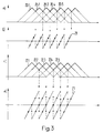
- Fig. 3a-d
- eine Darstellung der Korrelationskurven und Diskriminatorkennlinie für zwei verschiedene Umschaltkriterien;
- Fig. 4
- ein Blockschaltbild für eine auf einem DLL basierenden Test- und Umschaltlogik;
- Fig. 5
- ein Blockschaltbild für eine Test- und Umschaltlogik für eine auf dem Prinzip des MCTL basierenden Synchronisationsschaltung.
- Fig. 1
- A block diagram of a synchronization circuit according to the invention;
- 2a-e
- a schematic diagram of the correlation curves and discriminator characteristics when moving the control range according to the invention;
- 3a-d
- a representation of the correlation curves and discriminator characteristic for two different switching criteria;
- Fig. 4
- a block diagram for a DLL based test and switching logic;
- Fig. 5
- a block diagram for a test and switching logic for a synchronization circuit based on the principle of the MCTL.
Wie aus Fig. 1 zu entnehmen ist, wird ein Empfangssignal
r(t) auf drei schaltungsmässig im wesentlichen identische
Korrelationspfade aufgeteilt. In einem Mischer 1.1 resp. 1.2
resp. 1.3 wird das Empfangssignal r(t) mit einem PN-Code-Signal
definierter Phasenlage korreliert. In einem nachfolgenden
Bandpassfilter 2.1 resp. 2.2 resp. 2.3 wird das Ausgangssignal
des Mischers 1.1 resp. 1.2 resp. 1.3 in an sich
bekannter Weise gefiltert und dann einerseits über eine Leitung
4.1 resp. 4.2 resp. 4.3 direkt einer Synchronisationssteuerung
5 und andererseits einem Enveloppendetektor 3.1
resp. 3.2 resp. 3.3 zugeführt. Die Enveloppendetektoren 3.1,
3.2, 3.3 bilden z. B. den Absolutbetrag des Eingangssignals
oder das Amplitudenquadrat. Die mit den Enveloppendetektoren
3.1, 3.2, 3.3 erzeugten datenneutralen Korrelationssignale
werden ebenfalls der Synchronisationssteuerung 5 zugeführt.As can be seen from Fig. 1, a received signal
r (t) to three essentially identical in terms of circuitry
Correlation paths split. In a mixer 1.1 or 1.2
resp. 1.3, the received signal r (t) with a PN code signal
correlated defined phase position. In a subsequent one
Bandpass filter 2.1 respectively 2.2 resp. 2.3 becomes the output signal
the mixer 1.1 respectively. 1.2 resp. 1.3 in itself
filtered in a known manner and then on the one hand via a line
4.1 resp. 4.2 resp. 4.3
Die Synchronisationssteuerung 5 stellt das Herz der erfindungsgemässen
Schaltanordnung dar. Sie gibt an einem Ausgang
6 ein (entspreiztes) Signal zur Datendemodulation ab, aus
welchem mittels einer (nicht dargestellten) Demodulationsschaltung
die übermittelten Daten extrahiert werden. An einem
Ausgang 7 wird ein Fehlersignal e(t) ausgegeben, welches
über ein Kreisfilter 8 einem VCO 9 zugeführt wird. Dieser
VCO 9 stellt den Zeitgeber für einen PN-Code-Generator 10
dar, welcher gemäss der Erfindung an drei Ausgängen 11.1,
11.2, 11.3 bis auf die Phasenlage identische PN-Code-Signale
erzeugen kann. Die Phasenlage eines jeden PN-Code-Signals
ist innerhalb eines vorgegebenen Zeitrasters variierbar. Der
Zeitraster ist durch eine Zeitdifferenz deltaTc definiert.The
Die Synchronisationssteuerung 5 gibt ferner dem Kreisfilter
8 die beim nachfolgend beschriebenen Umschalten wichtigen
Anfangsbedingungen vor. Schliesslich gibt sie an den PN-Code-Generator
10 die Codepositionen resp. Phasenlagen für
die PN-Signale weiter.The
Andeutungsweise ist eine für eine allfällige heterodyne
Rückspreizung erforderliche Ergänzung der Schaltung eingezeichnet.
Es handelt sich dabei um einen Lokaloszillator 12
und je einen Multiplizierer/Mischer 13.1, 13.2, 13.3 für die
an den Ausgängen 11.1, 11.2, 11.3 abgegebenen PN-Code-Signale.Hint is one for any heterodyne
The necessary expansion of the circuit is drawn in.
It is a
Die Funktionsweise der Synchronisationssteuerung 5 soll anhand
der Fig. 2a-e erläutert werden. Es wird dabei davon
ausgegangen, dass an den Ausgängen 11.1, 11.2, 11.3 drei um
je deltaTc zeitlich gegeneinander verschobene PN-Code-Signale
abgegeben werden. Das (phasenmässig) mittlere PN-Code-Signal,
welches z. B. am Ausgang 11.2 abgegeben und im Mischer
1.2 mit dem Empfangssignal r(t) korreliert wird, wird
mittels des Synchronisationskreises insbesondere den steuerbaren
Zeitgeber (VCO 9) möglichst gut dem Empfangssignal
r(t) nachgeführt.The functioning of the
Für die folgenden Erläuterungen wird angenommen, dass am
Ausgang 11.1 das um deltaTc (in Fig. 2 wurde delta = 1 gewählt)
zeitlich vorverschobene, d. h. frühere, und dass am
Ausgang 11.3 das um deltaTc nachlaufende, d. h. spätere PN-Code-Signal
abgegeben wird. In den drei Korrelationspfaden
werden damit drei Korrelationskurven 14 (entsprechend dem
voreilenden Signal), 15 (entsprechend dem rechtzeitigen Signal)
und 16 (entsprechend dem nachlaufenden Signal) in Abhängigkeit
von der Phasenverschiebung des Empfangssignals
r(t) gegenüber dem phasenmässig mittleren PN-Code-Signal erzeugt.
Durch Subtraktion der voreilenden (early) von der
nachlaufenden (late) Korrelationskurve wird eine Kennlinie
17.1 erhalten, die im Prinzip einen Regelbereich der Breite
2 (Tc + deltaTc) erlaubt (ausserhalb dieses Bereiches verschwindet
die Kennlinie 17.1). Das Fehlersignal zur Nachführung
des VCO 9 hat eine Amplitude, die entsprechend dem Synchronisationsfehler
epsilon aus der Kennlinie 17.1 folgt.
Die Datendemodulation wird auf der Basis der mittleren Korrelationskurve
15 durchgeführt. Unter gewöhnlichen Umständen,
d. h. wenn keine Drift der Phasenlage des Empfangssignals
vorliegt, arbeitet die erfindungsgemässe Synchronisationsschaltung
nach dem Prinzip eines konventionellen DLL.
Verschiebt sich jedoch das Empfangssignal phasenmässig so
stark, dass die Leistung gemäss Korrelationskurve 15 kleiner
ist als in Korrelationskurve 14 oder 16, so wird die im folgenden
beschriebene Umschaltung durchgeführt.For the following explanations, it is assumed that at output 11.1 the delayed, ie earlier, delayed by deltaT c (delta = 1 was selected in FIG. 2) and that the subsequent PN code signal that follows deltaT c , ie later, at output 11.3 is delivered. In the three correlation paths, three correlation curves 14 (corresponding to the leading signal), 15 (corresponding to the timely signal) and 16 (corresponding to the trailing signal) are thus dependent on the phase shift of the received signal r (t) compared to the phase-average PN code Signal generated. By subtracting the leading (early) from the trailing (late) correlation curve, a characteristic curve 17.1 is obtained, which in principle allows a control range of width 2 (T c + deltaT c ) (characteristic curve 17.1 disappears outside this range). The error signal for tracking the
Angenommen die Phasenverschiebung zwischen Empfangssignal und dem zeitmittleren PN-Code-Signal wird (in positiver Richtung) immer grösser, dann wird ab einer bestimmten Phasendifferenz dephi (hierbei dephi > deltaTc/2) das Korrelationssignal im phasenmässig mittleren Korrelationspfad (Korrelationskurve 15) kleiner als dasjenige im nachlaufenden Korrelationspfad (Korrelationskurve 16). Gemäss der Erfindung wird nun die Phase des ursprünglich voreilenden PN-Code-Signals (Korrelationskurve 14) derart geändert, dass sie dem ehemals nachlaufenden PN-Code-Signal (Korrelationskurve 16) um deltaTc nacheilt (Korrelationskurve 19). Assuming the phase shift between the received signal and the mean-time PN code signal is getting larger (in the positive direction), then from a certain phase difference dephi (here dephi> deltaT c / 2) the correlation signal in the phase-median correlation path (correlation curve 15) becomes smaller than that in the trailing correlation path (correlation curve 16). According to the invention, the phase of the originally leading PN code signal (correlation curve 14) is now changed in such a way that it lags the previously trailing PN code signal (correlation curve 16) by deltaT c (correlation curve 19).
Gleichzeitig wird eine Neuzuordnung der Korrelationspfade in
dem Sinne durchgeführt, dass die Datendemodulation auf der
Basis der nunmehr (phasenmässig) mittleren Korrelationskurve
16 durchgeführt wird. Zur Erzeugung des Fehlersignals wird
die Differenz zwischen der Korrelationskurve 19 und der ehemals
mittleren Korrelationskurve 15 verwendet (vgl. Fig.
2d). Ein Vergleich der beiden Fig. 2b und d zeigt, dass anstelle
der Kennlinie 17.1 die zeitlich verschobene Kennlinie
17.2 getreten ist. Die Regelung erfolgt nun auch auf einem
anderen Nullpunkt (welcher ebenfalls um deltaTc verschoben
ist).At the same time, the correlation paths are reassigned in the sense that the data demodulation is carried out on the basis of the now (phase-wise) mean
In völlig analoger Weise kann auch eine Drift in Rückwärtsrichtung
ausgeglichen werden. Durch Aneinanderreihung der
erfindungsgemässen Regelbereiche 18.1, 18.2 etc. ergibt sich
die erfindungsgemässe, stückweise stetige, sägezahnförmige
Kennlinie 17 gemäss Fig. 2e.In a completely analogous way, a drift in the reverse direction can also occur
be balanced. By lining up the
Control ranges 18.1, 18.2 etc. according to the invention result
the piecewise, sawtooth-shaped according to the
Da sich beim Umschalten eines der drei PN-Code-Signale und
der Neuzuordnung der Korrelationspfade nicht nur der relative
Synchronisationsfehler ändert (gemäss Fig. 2c von
+deltaTc/2 auf -deltaTc/2), sondern auch der Wert des Fehlersignals,
muss der Wert des Ausgangssignals des Kreisfilters
8 entsprechend dem Wert in der neuen Diskriminatorkennlinie
initialisiert werden (durch Vorgabe der Anfangsbedingungen
an das Kreisfilter 8).Since when switching one of the three PN code signals and reallocating the correlation paths, not only the relative synchronization error changes (from Fig. 2c from + deltaT c / 2 to -deltaT c / 2), but also the value of the error signal the value of the output signal of the
Der ganze oben beschriebene Umschaltvorgang wird von der
Synchronisationssteuerung 5 durchgeführt. Sie testet die
Korrelationswerte in den drei Pfaden, bestimmt die notwendigen
Verschiebungen der einzelnen PN-Code-Signale, setzt die
Anfangsbedingung für das Ausgangssignal des Kreisfilters 8
und ändert die Zuordnung zwischen den über die Leitungen
4.1, 4.2, 4.3 zugeführten Korrelationssignalen und dem Ausgang
6. The whole switching process described above is from the
Das Prinzip der Erfindung wurde anhand des Falles delta = 1 erläutert. Mit Vorteil werden aber kleinere Werte für delta implementiert, z. B. delta = 0,5. In Fig. 3a-d sind zwei Beispiele für delta = 0,5 mit unterschiedlichen Umschaltkriterien dargestellt. Wie in Fig. 3 zu erkennen ist, sind die einzelnen Korrelationskurven 20.1, ..., 20.5 viel näher beabstandet als beim Beispiel gemäss Fig. 2a. Als Umschaltkriterium wurde wiederum die Bedingung gewählt, dass die Leistung (Wert der Korrelationskurve) im voreilenden bzw. nachlaufenden Pfad grösser als im mittleren ist. Die resultierende Diskriminatorkennlinie 21 unterscheidet sich von der in Fig. 2e gezeigten nur durch eine andere Periodizität. Im Vergleich zum obigen Beispiel ist jedoch die Leistung des zur Datendemodulation benutzten Signals immer ziemlich gross. Im Prinzip fällt sie nie mehr als um einen Viertel der maximalen Korrelationsleistung ab.The principle of the invention was based on the case delta = 1 explained. However, smaller values for delta are advantageous implemented, e.g. B. delta = 0.5. 3a-d are two Examples for delta = 0.5 with different switchover criteria shown. As can be seen in Fig. 3, the individual correlation curves 20.1, ..., 20.5 spaced much closer than in the example according to FIG. 2a. As a switchover criterion again the condition was chosen that the performance (Value of the correlation curve) in the leading or trailing Path is larger than in the middle. The resulting one Discriminator characteristic 21 differs from that shown in Fig. 2e only by a different periodicity. in the However, compared to the example above, the performance of the signal used for data demodulation always pretty much large. In principle, it never falls by more than a quarter the maximum correlation power.
Besonders bevorzugt ist ein Umschaltkriterium, welches zu einer Hysterese der Diskriminatorkennlinie führt. Ein Beispiel für eine Umschaltung mit Hysterese ist aus den Fig. 3c und d zu entnehmen. In diesem Beispiel wird immer dann umgeschaltet, wenn die Leistung im voreilenden oder nachlaufenden Pfad zweimal so gross wie im mittleren ist. Aufgrund des geringeren Abstandes der Korrelationskurven 22.1, ..., 22.5 (im Vergleich zu Fig. 2) entsteht die bevorzugte, mittels Pfeilen angedeutete Hysterese in der Diskriminatorkennlinie 23. Es ist zu beachten, dass im Idealfall beim Umschalten der Phasenfehler verschwindet, da die neue "Ruhelage" mit dem "Grenzpunkt" der noch nicht umgeschalteten Kennlinie zusammenfällt.A switchover criterion which is particularly preferred is leads to a hysteresis of the discriminator characteristic. An example for a switchover with hysteresis is from Fig. 3c and d. In this example, we always switch over if the performance in the leading or trailing Path is twice the size of the middle one. Because of the smaller distance between the correlation curves 22.1, ..., 22.5 (compared to Fig. 2), the preferred, means Arrows indicated hysteresis in the discriminator characteristic 23. It should be noted that ideally when switching the phase error disappears because the new "rest position" with the "limit point" of the characteristic which has not yet been switched over coincides.
Es leuchtet ein, dass bei delta = 0,5 jedes Umschaltkriterium, das stärker als das in Fig. 3a, b verwendete ist, zu einer Schalthysterese führt. Mit anderen Worten: Immer wenn gefordert ist, dass die Leistung im voreilenden oder nachlaufenden Pfad um einen bestimmten Wert grösser sein muss als die im mittleren Pfad, liegt eine Hysterese vor. Bedingung ist allerdings, dass delta < 1 gilt.It is obvious that with delta = 0.5 each switchover criterion, which is stronger than that used in Fig. 3a, b a switching hysteresis. In other words: whenever It is required that the performance in the leading or trailing Path must be larger by a certain value than that in the middle path, there is a hysteresis. condition is, however, that delta <1 applies.
In den Fig. 2a-e und 3a-d wurden die Korrelationskurven für den Fall betragsbildender Enveloppendetektoren 3.1, 3.2, 3.3 dargestellt. Diese Kurvenformen ändern sich natürlich, wenn die Enveloppendetektoren z. B. die Amplitude quadrieren. Die Umschaltbedingungen sind dann entsprechend anzupassen.2a-e and 3a-d the correlation curves for the case of amount-forming envelope detectors 3.1, 3.2, 3.3 shown. Of course, these curve shapes change when the envelope detectors e.g. B. square the amplitude. The Changeover conditions must then be adjusted accordingly.
Die Hysterese hat zur Folge, dass ein allzu schnelles mehrmaliges Hin- und Herschalten, das z. B. durch Störungen hervorgerufen werden kann, vermieden wird.The result of the hysteresis is that it is repeated too quickly Toggle back and forth, the z. B. caused by interference can be avoided.
Hysteresen lassen sich mit den unterschiedlichsten Mitteln herbeiführen. So können z. B. auch mehr als drei Korrelationspfade vorgesehen werden, wobei ein Umschalten durch Ueberwachung der Signalleistung in den verschiedenen Korrelationspfaden und Durchschalten des Pfades maximaler Leistung zur Datendemodulation verbessert werden. Bei vier oder fünf parallelen Korrelationspfaden ist ja nicht nur ein mittlerer Pfad vorhanden und ein Umschalten resp. Verschieben des Regelbereiches kann länger hinausgeschoben werden, ohne dass die Leistung im Demodulationspfad allzu klein wird. Bei fünf Korrelationspfaden gibt es beispielsweise drei mittlere Pfade, die wahlweise nach dem Kriterium maximaler Leistung für die Datendemodulation herangezogen werden können. Solange das Empfangssignal nicht in den Bereich des frühesten resp. spätesten Korrelationssignals hineinläuft sind nämlich keine Phasenschiebungen erforderlich.Hysteresis can be done with a variety of means bring about. So z. B. also more than three correlation paths are provided, with a switching by Monitoring the signal power in the different correlation paths and switching the path of maximum power be improved for data demodulation. At four or five parallel correlation paths is not just one middle path available and a switch respectively. Move the control range can be postponed longer, without the performance in the demodulation path being too small becomes. For example, there are five correlation paths three middle paths, optionally based on the maximum criterion Performance can be used for data demodulation can. As long as the received signal is not in the range of earliest resp. latest correlation signal runs in namely, no phase shifts are required.
Fig. 4 zeigt ein Blockschaltbild der Synchronisationssteuerung
5. Eine Schaltmatrix 24 ist so ausgebildet, dass entsprechend
von Steuersignalen der Umschaltsteuerung 29 wahlweise
eines der an den Eingängen 26.1, 26.2, 26.3 anliegenden
Daten enthaltenden Signale auf den Ausgang 27.1 zwecks
Datendemodulation geschaltet werden kann. Die Enveloppen der
Signale werden an Eingängen 30.1, 30.2, 30.3 der Umschaltsteuerung
29 zugeführt. Diese führt die anhand der Fig. 2a-e
und 3a-d erläuterten Tests durch und ermittelt die Neuzuordnung
der Korrelationspfade, die Anfangsbedingungen für das
Kreisfilter 8 (Ausgang 32) und die Code-Position resp. Phasenlage
für den PN-Code-Generator 10 (Ausgang 31).Fig. 4 shows a block diagram of the
Die Schaltmatrix 24 hat auch Eingänge 25.1, 25.2, 25.3 für
die datenneutralen Ausgangssignale der Enveloppendetektoren
3.1, 3.2, 3.3 (vgl. Fig. 1). Zwei von diesen drei Eingängen
werden entsprechend den Steuersignalen der Umschaltsteuerung
29 auf die Ausgänge 27.2 und 27.3 gegeben. Ein Subtrahierer
28 bildet die Differenz und gibt diese als Fehlersignal
(Eingangssignal des Kreisfilters 8) aus.The switching matrix 24 also has inputs 25.1, 25.2, 25.3 for
the data-neutral output signals of the envelope detectors
3.1, 3.2, 3.3 (see Fig. 1). Two of these three entrances
are in accordance with the control signals of the switching
Fig. 5 zeigt schliesslich ein Blockschaltbild einer Synchronisationssteuerung
für eine Synchronisation nach dem Prinzip
des MCTL (Modified-Code-Tracking-Loop). An den Eingängen
34.1, 34.2, 34.3 einer Schaltmatrix 33 liegen die datentragenden
Korrelationssignale (vgl. Leitungen 4.1, 4.2, 4.3 in
Fig. 1) an. Die genannten Eingangssignale werden entsprechend
den Signalen einer Umschaltsteuerung 41 wahlweise auf
die Ausgänge 35, 36, 37 geführt. Der Ausgang 35 wird für die
Datendemodulation verwendet. Die Ausgänge 36 und 37 werden
in einem Subtrahierer 38 voneinander subtrahiert. Die resultierende
Differenz wird in einem Multiplizierer 39 mit dem
am Ausgang 35 abgegebenen Signal multipliziert. Daraus resultiert
an einem Ausgang 40 das Fehlersignal, das über ein
Kreisfilter an einen VCO gegeben wird. 5 finally shows a block diagram of a synchronization control
for synchronization according to the principle
of the MCTL (Modified Code Tracking Loop). At the entrances
34.1, 34.2, 34.3 of a switching
An den Eingängen 42.1, 42.2, 42.3 der Umschaltsteuerung 41
liegen die Ausgangssignale der Enveloppendetektoren an. Auf
der anderen Seite werden an Ausgängen 43 und 44 Code-Positionen
(für den PN-Code-Generator) resp. Anfangsbedingungen
(für das Kreisfilter) abgegeben.At the inputs 42.1, 42.2, 42.3 of the
Die Erfindung ist im übrigen auch auf weitere bekannte Regel-Strukturen anwendbar. Eine solche Struktur ist z. B. der an sich bekannte Tau-Dither-Loop. Aehnlich wie beim DLL wird beim Tau-Dither-Loop durch die Erfindung eine periodische Diskriminatorkennlinie erzeugt. Dasselbe gilt auch für den sogenannten Double-Dither-Loop.The invention is also based on other known control structures applicable. Such a structure is e.g. B. the known tau dither loop. Similar to what happens with the DLL in the tau dither loop by the invention a periodic Discriminator characteristic generated. The same applies to the so-called double dither loop.
Mit dem neuen PN-Code Tracking-Loop gemäss der Erfindung ist es somit möglich, mit drei gegeneinander verschobenen und adaptiv umschaltbaren Korrelationspfaden eine periodische Diskriminatorkennlinie zu erzeugen. Infolgedessen ist es möglich, schnelle dynamische Vorgänge mit einem schmalbandigen Regelkreis mit einem Kreisfilter niedriger Ordnung verfolgen zu können. Das erfindungsgemässe Schaltungskonzept kann auch für die Grobsynchronisation eingesetzt werden und führt zu einer wesentlichen Beschleunigung. Da alle drei Korrelationsarme identisch aufgebaut sind und eine Leistungsmessung in allen Armen möglich ist, kann eine Grobsynchronisation rund dreimal schneller durchgeführt werden als mit einer Synchronisationsschaltung, bei der nur ein Korrelationspfad für eine Leistungsmessung zur Verfügung steht. With the new PN code tracking loop according to the invention it is thus possible with three shifted and adaptively switchable correlation paths a periodic Generate discriminator characteristic. As a result, it is possible fast dynamic processes with a narrow band Track the control loop with a low-order loop filter to be able to. The circuit concept according to the invention can also be used for coarse synchronization and leads to a significant acceleration. Because all three Correlation arms are constructed identically and a performance measurement Coarse synchronization is possible in all arms about three times faster than with a synchronization circuit in which only one correlation path is available for a performance measurement.
- 1.1, 1.2, 1.31.1, 1.2, 1.3
- Mischermixer
- 2.1, 2.2, 2.32.1, 2.2, 2.3
- BandpassfilterBandpass filter
- 3.1, 3.2, 3.33.1, 3.2, 3.3
- EnveloppendetektorEnvelope detector
- 4.1, 4.2, 4.34.1, 4.2, 4.3
- Leitungmanagement
- 55
- SynchronisationssteuerungSynchronization control
- 66
- Ausgangexit
- 77
- Ausgangexit
- 88th
- KreisfilterCircular filter
- 99
- VCOVCO
- 1010th
- PN-Code-GeneratorPN code generator
- 11.1, 11.2, 11.311.1, 11.2, 11.3
- Ausgangexit
- 1212th
- LokaloszillatorLocal oscillator
- 13.1, 13.2, 13.313.1, 13.2, 13.3
- MultipliziererMultiplier
- 14, 15, 1614, 15, 16
- KorrelationskurvenCorrelation curves
- 17, 17.1, 17.217, 17.1, 17.2
- Kennliniecurve
- 18.1, 18.218.1, 18.2
- RegelbereichControl range
- 1919th
- KorrelationskurveCorrelation curve
- 20.1, ..., 20.520.1, ..., 20.5
- KorrelationskurveCorrelation curve
- 2121
- DiskriminatorkennlinieDiscriminator curve
- 22.1, ..., 22.522.1, ..., 22.5
- KorrelationskurveCorrelation curve
- 2323
- DiskriminatorkennlinieDiscriminator curve
- 2424th
- SchaltmatrixSwitching matrix
- 25.1, 25.2, 25.325.1, 25.2, 25.3
- Eingangentrance
- 26.1, 26.2, 26.326.1, 26.2, 26.3
- Eingangentrance
- 27.1, 27.2, 27.327.1, 27.2, 27.3
- Ausgangexit
- 2828
- SubtrahiererSubtractor
- 2929
- UmschaltsteuerungSwitching control
- 30.1, 30.2, 30.330.1, 30.2, 30.3
- Eingangentrance
- 31, 3231, 32
- Ausgangexit
- 3333
- SchaltmatrixSwitching matrix
- 34.1, 34.2, 34.334.1, 34.2, 34.3
- Eingang entrance
- 35, 36, 3735, 36, 37
- Ausgangexit
- 3838
- SubtrahiererSubtractor
- 3939
- MultipliziererMultiplier
- 4040
- Ausgangexit
- 4141
- UmschaltsteuerungSwitching control
- 42.1, 42.2, 42.342.1, 42.2, 42.3
- Eingangentrance
- 43, 4443, 44
- Ausgangexit
Claims (8)
- Method of synchronising a receiver circuit with a received signal which includes a data signal expanded by a PN code, in which at least three PN-code signals, offset relative to one another in time, are produced on the basis of an adjustable timer, and in which a PN-code signal which is central in time is correlated with the received signal for data-modulation purposes in a first correlation path, and a leading PN-code signal and a trailing PN-code signal are correlated with the received signal in a second correlation path and in a third correlation path, respectively, for the purpose of adjusting the timer, characterized in that, upon a forward or a rearward drift of the data signal in time, a range of adjustment defined by the leading and the trailing PN-code signals is shifted adaptively by shifting of the trailing or the leading PN-code signal, respectively, by a predetermined time interval to the foremost or to the rearmost position, respectively, and by the execution of a data-modulation with the PN-code signal which is now central, with re-allocation of the PN-code signals.
- Method according to Claim 1, characterized in that precisely three PN-code signals out of phase by deltaTc, respectively, are produced, and in that, during the adaptive shifting of the range of adjustment, the leading or the trailing PN-code signal is shifted by 3 deltaTc to the rearmost or to the foremost position, respectively.
- Method according to Claim 1 or Claim 2, characterized in that delta = 0.5 is selected.
- Method according to Claim 1 or Claim 2, characterized in that delta = 1 is selected.
- Method according to any one of Claims 1 to 4, characterized in that a shift of the range of adjustment always takes place when the power in the central correlation path is less than in one of the outermost correlation paths.
- Method according to any one of Claims 1 to 4, characterized in that a shift of the range of adjustment always takes place when the power of the central correlation path is less than half of that in one of the outermost correlation paths.
- Synchronization circuit includingcharacterized in thata) an adjustable timer (9)b) a PN-code generator (10) with at least three outputs (11.1, 11.2, 11.3) for producing at least three PN-code signals out of phase with one another,c) at each output (11.1, 11.2, 11.3) of the PN-code generator (10), a correlation path with a mixer (1.1, 1.2, 1.3) for correlating the received signal (r(t)) with a respective PN-code signal and a control-signal circuit for readjusting the timer (9),
d) a switching matrix (24) is provided, by means of which it is possible selectively to route two adaptively definable correlation paths to the control circuit (8, 9) and one to a demodulation circuit, and in that the PN-code generator (10) is formed in a manner such that the phase positions of the respective PN-code signals supplied at the outputs (11.1, 11.2, 11.3) can be phase-shifted by predetermined intervals. - Receiver for spread-spectrum message signals, characterized by a synchronization circuit according to Claim 7.
Applications Claiming Priority (2)
| Application Number | Priority Date | Filing Date | Title |
|---|---|---|---|
| CH304092 | 1992-09-29 | ||
| CH3040/92 | 1992-09-29 |
Publications (3)
| Publication Number | Publication Date |
|---|---|
| EP0590298A2 EP0590298A2 (en) | 1994-04-06 |
| EP0590298A3 EP0590298A3 (en) | 1994-06-01 |
| EP0590298B1 true EP0590298B1 (en) | 1998-04-15 |
Family
ID=4247274
Family Applications (1)
| Application Number | Title | Priority Date | Filing Date |
|---|---|---|---|
| EP93113446A Expired - Lifetime EP0590298B1 (en) | 1992-09-29 | 1993-08-24 | Synchronisation procedure of a receiver for the reception of a data signal spread by a PN-code |
Country Status (3)
| Country | Link |
|---|---|
| US (1) | US5436935A (en) |
| EP (1) | EP0590298B1 (en) |
| DE (1) | DE59308402D1 (en) |
Families Citing this family (18)
| Publication number | Priority date | Publication date | Assignee | Title |
|---|---|---|---|---|
| US6111911A (en) * | 1995-06-07 | 2000-08-29 | Sanconix, Inc | Direct sequence frequency ambiguity resolving receiver |
| US5600328A (en) * | 1995-06-21 | 1997-02-04 | Matsushita Electric Industrial Co., Ltd. | Demodulator circuit in global positioning system receiver |
| US5953367A (en) * | 1995-08-09 | 1999-09-14 | Magellan Corporation | Spread spectrum receiver using a pseudo-random noise code for ranging applications in a way that reduces errors when a multipath signal is present |
| DE69637296T2 (en) * | 1995-08-09 | 2008-09-04 | Magellan Navigation, Inc. (n.d.Ges.d.Staates Delaware), Santa Clara | DETECTION AND LOCATION OF CURRENT DEFECTS AND DETECTION OF VIBRATIONS |
| KR970078064A (en) * | 1996-05-31 | 1997-12-12 | 배순훈 | Pseudo-noise control device for digital DL |
| US5805646A (en) * | 1996-10-08 | 1998-09-08 | Ericsson Inc. | Synchronization method, and associated circuitry, for improved synchronization of a receiver with a transmitter using early-late testing during coarse synchronization |
| US6079007A (en) * | 1998-03-10 | 2000-06-20 | Pan Atlantic Corporation | System and method for generating pseudo-random codes |
| US6237075B1 (en) * | 1998-03-10 | 2001-05-22 | Pan Atlantic Corporation | System and method for generating pseudo-random codes |
| US7224713B2 (en) * | 1998-04-09 | 2007-05-29 | Andrzej Partyka | Telemetry system with authentication |
| JP3825179B2 (en) * | 1998-07-17 | 2006-09-20 | 富士通株式会社 | Correlator |
| US6967974B1 (en) | 1999-09-30 | 2005-11-22 | Andrzej Partyka | Transmission of urgent messages in telemetry system |
| US6894975B1 (en) * | 2000-01-15 | 2005-05-17 | Andrzej Partyka | Synchronization and access of the nodes in a communications network |
| US6925105B1 (en) | 2000-05-01 | 2005-08-02 | Andrzej Partyka | Overhead reduction in system for intermittent transmission |
| KR100333818B1 (en) * | 2000-08-16 | 2002-04-26 | 윤종용 | Apparatus for detecting mode by using null symbols in digital audio receiver and method thereof |
| US7209495B2 (en) | 2000-09-28 | 2007-04-24 | Andrzej Partyka | Urgent messages and power-up in frequency hopping system for intemittent transmission |
| US6834040B2 (en) * | 2001-02-15 | 2004-12-21 | Agilent Technologies, Inc. | Measurement synchronization method for voice over packet communication systems |
| ES2257923B1 (en) * | 2004-05-24 | 2007-07-01 | Universitat Politecnica De Catalunya | SYNCHRONOUS HIGH PERFORMANCE SUPERREGENERATIVE RECEIVER. |
| US10957445B2 (en) | 2017-10-05 | 2021-03-23 | Hill-Rom Services, Inc. | Caregiver and staff information system |
Family Cites Families (6)
| Publication number | Priority date | Publication date | Assignee | Title |
|---|---|---|---|---|
| US4638494A (en) * | 1970-08-19 | 1987-01-20 | Sperry Corporation | System for the acquisition of code signals |
| US4203071A (en) * | 1978-08-08 | 1980-05-13 | The Charles Stark Draper Laboratory, Inc. | Pseudo-random-number-code-detection and tracking system |
| US4221005A (en) * | 1979-05-21 | 1980-09-02 | Nasa | Pseudonoise code tracking loop |
| US5090023A (en) * | 1986-09-29 | 1992-02-18 | Kabushiki Kaisha Kenwood | Spread spectrum communication system |
| DE3743731C2 (en) * | 1987-12-23 | 1994-11-24 | Ant Nachrichtentech | Method and circuit arrangement for regulating the phase position between a generated code and a received code contained in a received spectrally spread signal |
| DE3743732C2 (en) * | 1987-12-23 | 1994-12-01 | Ant Nachrichtentech | Method for synchronizing a code word with a received spectrally spread signal |
-
1993
- 1993-08-24 EP EP93113446A patent/EP0590298B1/en not_active Expired - Lifetime
- 1993-08-24 DE DE59308402T patent/DE59308402D1/en not_active Expired - Fee Related
- 1993-09-13 US US08/119,546 patent/US5436935A/en not_active Expired - Fee Related
Also Published As
| Publication number | Publication date |
|---|---|
| EP0590298A3 (en) | 1994-06-01 |
| EP0590298A2 (en) | 1994-04-06 |
| DE59308402D1 (en) | 1998-05-20 |
| US5436935A (en) | 1995-07-25 |
Similar Documents
| Publication | Publication Date | Title |
|---|---|---|
| EP0590298B1 (en) | Synchronisation procedure of a receiver for the reception of a data signal spread by a PN-code | |
| DE19753473C2 (en) | frequency multiplier | |
| WO1991006164A1 (en) | Digital receiver for band-spread signals | |
| DE19836582A1 (en) | Correcting carrier wave frequency shift in direct sequence band spread communication system | |
| DE10127293A1 (en) | Timer circuit with dual phase locked loops | |
| DE69924277T2 (en) | METHOD AND CIRCUIT FOR GENERATING A VARIABLE CLOCK FREQUENCY | |
| DE3743732C2 (en) | Method for synchronizing a code word with a received spectrally spread signal | |
| DE1918554B2 (en) | CIRCUIT FOR GENERATING A SAW TOOTH CURRENT FOR THE DEFLECTION OF A TUBE IN A TELEVISION RECEIVER | |
| DE2749493C2 (en) | Signal generator | |
| DE2048055C1 (en) | Procedure for determining the | |
| EP0590323B1 (en) | Filter for adjusting the band width of a control loop | |
| DE3743731A1 (en) | Method and circuit arrangement for controlling the phase angle between a generated code and a received code contained in a received spread-spectrum signal | |
| DE2507609C2 (en) | Acquisition system for an SDMA / TDMA satellite communications system | |
| EP3751308B1 (en) | Method for determining the distance between two objects, in particular two satellites | |
| DE2623002C3 (en) | Converter for converting the clock frequency of digital signals | |
| DE60125764T2 (en) | LINEAR DIGITAL PHASE DETECTION WITHOUT DEAD AREA | |
| DE10157437A1 (en) | Circuit arrangement for clock and data recovery from received signal combines first and second groups of intermediate signals to form combined signals for data and clock recovery | |
| DE3028945C2 (en) | Tuning device with phase-synchronized loop and measures for automatic fine-tuning | |
| DE3306517A1 (en) | CIRCUIT ARRANGEMENT FOR SELECTIVELY SUPPLYING A SHARP TUNING CIRCUIT TO IMPROVE THE LOOP STABILITY IN A PLL TUNING SYSTEM | |
| DE3327114C2 (en) | Pulse generator for generating sampling pulses | |
| DE2749736A1 (en) | DIGITAL CARRIER CORRECTION CIRCUIT | |
| WO2004036781A1 (en) | Device and method for tracking a sampling instant in radio receivers | |
| DE60121311T2 (en) | RAKE RECEIVER AND METHOD FOR OPERATING A RAKE RECEIVER | |
| DE102004038100B3 (en) | Generation of a clock with spread frequency spectrum | |
| DE2024818C3 (en) | Dekodierschaltiingsanordniuig for a signal transmission system with information transmission by means of a quadrature-modulated carrier, in particular for color television signals |
Legal Events
| Date | Code | Title | Description |
|---|---|---|---|
| PUAI | Public reference made under article 153(3) epc to a published international application that has entered the european phase |
Free format text: ORIGINAL CODE: 0009012 |
|
| AK | Designated contracting states |
Kind code of ref document: A2 Designated state(s): CH DE FR GB LI SE |
|
| PUAL | Search report despatched |
Free format text: ORIGINAL CODE: 0009013 |
|
| AK | Designated contracting states |
Kind code of ref document: A3 Designated state(s): CH DE FR GB LI SE |
|
| 17P | Request for examination filed |
Effective date: 19940916 |
|
| GRAG | Despatch of communication of intention to grant |
Free format text: ORIGINAL CODE: EPIDOS AGRA |
|
| 17Q | First examination report despatched |
Effective date: 19970807 |
|
| GRAG | Despatch of communication of intention to grant |
Free format text: ORIGINAL CODE: EPIDOS AGRA |
|
| GRAH | Despatch of communication of intention to grant a patent |
Free format text: ORIGINAL CODE: EPIDOS IGRA |
|
| RAP1 | Party data changed (applicant data changed or rights of an application transferred) |
Owner name: ASCOM TECH AG |
|
| GRAH | Despatch of communication of intention to grant a patent |
Free format text: ORIGINAL CODE: EPIDOS IGRA |
|
| GRAA | (expected) grant |
Free format text: ORIGINAL CODE: 0009210 |
|
| AK | Designated contracting states |
Kind code of ref document: B1 Designated state(s): CH DE FR GB LI SE |
|
| REG | Reference to a national code |
Ref country code: CH Ref legal event code: NV Representative=s name: KELLER & PARTNER PATENTANWAELTE AG Ref country code: CH Ref legal event code: EP |
|
| REF | Corresponds to: |
Ref document number: 59308402 Country of ref document: DE Date of ref document: 19980520 |
|
| GBT | Gb: translation of ep patent filed (gb section 77(6)(a)/1977) |
Effective date: 19980715 |
|
| ET | Fr: translation filed | ||
| PLBE | No opposition filed within time limit |
Free format text: ORIGINAL CODE: 0009261 |
|
| STAA | Information on the status of an ep patent application or granted ep patent |
Free format text: STATUS: NO OPPOSITION FILED WITHIN TIME LIMIT |
|
| 26N | No opposition filed | ||
| PGFP | Annual fee paid to national office [announced via postgrant information from national office to epo] |
Ref country code: FR Payment date: 20010705 Year of fee payment: 9 |
|
| PGFP | Annual fee paid to national office [announced via postgrant information from national office to epo] |
Ref country code: GB Payment date: 20010713 Year of fee payment: 9 Ref country code: CH Payment date: 20010713 Year of fee payment: 9 |
|
| PGFP | Annual fee paid to national office [announced via postgrant information from national office to epo] |
Ref country code: SE Payment date: 20010716 Year of fee payment: 9 |
|
| PGFP | Annual fee paid to national office [announced via postgrant information from national office to epo] |
Ref country code: DE Payment date: 20010718 Year of fee payment: 9 |
|
| REG | Reference to a national code |
Ref country code: GB Ref legal event code: IF02 |
|
| PG25 | Lapsed in a contracting state [announced via postgrant information from national office to epo] |
Ref country code: GB Free format text: LAPSE BECAUSE OF NON-PAYMENT OF DUE FEES Effective date: 20020824 |
|
| PG25 | Lapsed in a contracting state [announced via postgrant information from national office to epo] |
Ref country code: SE Free format text: LAPSE BECAUSE OF NON-PAYMENT OF DUE FEES Effective date: 20020825 |
|
| PG25 | Lapsed in a contracting state [announced via postgrant information from national office to epo] |
Ref country code: LI Free format text: LAPSE BECAUSE OF NON-PAYMENT OF DUE FEES Effective date: 20020831 Ref country code: CH Free format text: LAPSE BECAUSE OF NON-PAYMENT OF DUE FEES Effective date: 20020831 |
|
| PG25 | Lapsed in a contracting state [announced via postgrant information from national office to epo] |
Ref country code: DE Free format text: LAPSE BECAUSE OF NON-PAYMENT OF DUE FEES Effective date: 20030301 |
|
| EUG | Se: european patent has lapsed | ||
| REG | Reference to a national code |
Ref country code: CH Ref legal event code: PL |
|
| GBPC | Gb: european patent ceased through non-payment of renewal fee |
Effective date: 20020824 |
|
| PG25 | Lapsed in a contracting state [announced via postgrant information from national office to epo] |
Ref country code: FR Free format text: LAPSE BECAUSE OF NON-PAYMENT OF DUE FEES Effective date: 20030430 |
|
| REG | Reference to a national code |
Ref country code: FR Ref legal event code: ST |