EP0589177B1 - Monocular telescope having constant length - Google Patents
Monocular telescope having constant length Download PDFInfo
- Publication number
- EP0589177B1 EP0589177B1 EP93112019A EP93112019A EP0589177B1 EP 0589177 B1 EP0589177 B1 EP 0589177B1 EP 93112019 A EP93112019 A EP 93112019A EP 93112019 A EP93112019 A EP 93112019A EP 0589177 B1 EP0589177 B1 EP 0589177B1
- Authority
- EP
- European Patent Office
- Prior art keywords
- magnification
- setting member
- monocular telescope
- eyepiece
- focussing unit
- Prior art date
- Legal status (The legal status is an assumption and is not a legal conclusion. Google has not performed a legal analysis and makes no representation as to the accuracy of the status listed.)
- Expired - Lifetime
Links
Images


Classifications
-
- G—PHYSICS
- G02—OPTICS
- G02B—OPTICAL ELEMENTS, SYSTEMS OR APPARATUS
- G02B23/00—Telescopes, e.g. binoculars; Periscopes; Instruments for viewing the inside of hollow bodies; Viewfinders; Optical aiming or sighting devices
- G02B23/02—Telescopes, e.g. binoculars; Periscopes; Instruments for viewing the inside of hollow bodies; Viewfinders; Optical aiming or sighting devices involving prisms or mirrors
- G02B23/06—Telescopes, e.g. binoculars; Periscopes; Instruments for viewing the inside of hollow bodies; Viewfinders; Optical aiming or sighting devices involving prisms or mirrors having a focussing action, e.g. parabolic mirror
-
- G—PHYSICS
- G02—OPTICS
- G02B—OPTICAL ELEMENTS, SYSTEMS OR APPARATUS
- G02B23/00—Telescopes, e.g. binoculars; Periscopes; Instruments for viewing the inside of hollow bodies; Viewfinders; Optical aiming or sighting devices
-
- G—PHYSICS
- G02—OPTICS
- G02B—OPTICAL ELEMENTS, SYSTEMS OR APPARATUS
- G02B7/00—Mountings, adjusting means, or light-tight connections, for optical elements
- G02B7/02—Mountings, adjusting means, or light-tight connections, for optical elements for lenses
- G02B7/04—Mountings, adjusting means, or light-tight connections, for optical elements for lenses with mechanism for focusing or varying magnification
Landscapes
- Physics & Mathematics (AREA)
- General Physics & Mathematics (AREA)
- Optics & Photonics (AREA)
- Astronomy & Astrophysics (AREA)
- Telescopes (AREA)
- Aiming, Guidance, Guns With A Light Source, Armor, Camouflage, And Targets (AREA)
- Lens Barrels (AREA)
- Gears, Cams (AREA)
- Shaping By String And By Release Of Stress In Plastics And The Like (AREA)
- Prostheses (AREA)
Abstract
Description
Die Erfindung betrifft ein monokulares Fernrohr konstanter Länge gemäß dem Oberbegriff des Anspruchs 1 (Siehe Sov. J. Opt. Technol., Vol. 43, No. 6, P. 360; Juni 1976).The invention relates to a monocular telescope of constant length according to the preamble of claim 1 (see Sov. J. Opt. Technol., Vol. 43, No. 6, P. 360; June 1976).
Aus der DE-OS 20 05 396 ist ein Fernrohr mit einer Fokussiervorrichtung bekannt, bei dem ein drehbarer Fokussiertrieb auf ein im Tubus des Fernrohrs axial verschiebbares Fokussierglied wirkt. Als getriebliche Verbindung zwischen dem Fokussiertrieb und dem Fokussierglied ist ein Exzenter mit einer in sich geschlossenen Gleitfläche vorgesehen. Auf diese Weise wird bei gleichbleibender Drehrichtung des Fokussiertriebes der gesamte Fokussierbereich mit einer halben bis einer ganzen Umdrehung des Fokussiertriebes erfaßt. Zur Über- oder Untersetzung des durch den Exzenter erzielten Verschiebungsbetrages ist zwischen diesem und dem Fokussierglied ein Übersetzungsgetriebe angeordnet. Dieses bekannte Fernrohr weist eine konstante Vergrößerung und ein feststehendes Okular auf.From DE-OS 20 05 396 a telescope with a focusing device is known, in which a rotatable focusing drive acts on a focusing member axially displaceable in the tube of the telescope. An eccentric with a self-contained sliding surface is provided as the gear connection between the focusing drive and the focusing member. In this way, with the direction of rotation of the focusing drive remaining the same, the entire focusing area is detected with half to a full revolution of the focusing drive. To increase or decrease the amount of displacement achieved by the eccentric, a transmission gear is arranged between it and the focusing member. This known telescope has a constant magnification and a fixed eyepiece.
Aus der DE-PS 1 109 398 ist ein Teleskop mit veränderbarer Vergrößerung bekannt, dessen Okularrohr je nach der gewählten Vergrößerung auf verschiedene Weiten ausgezogen wird. Das Okularrohr ist in einer Kurvenhülse mit einem Kurvenschlitz zur zwangsläufigen Drehung beim Verändern des Auszuges geführt und längsverschiebbar, jedoch relativ unverdrehbar mit dem Träger eines Umkehrsystems gekuppelt, der seinerseits mit einem zweiten Kurvenschlitz zur zwangsläufigen Verschiebung beim Verdrehen in der Kurvenhülse geführt ist. Dadurch sind auch starke Änderungen in der Fernrohrvergrößerung erreichbar. Die Scharfeinstellung erfolgt mittels einer Feineinstellmutter, wobei die einmal für eine bestimmte Entfernung eingestellte Schärfe über den gesamten Vergrößerungsbereich kontinuierlich erhalten bleibt.From DE-PS 1 109 398 a telescope with variable magnification is known, the eyepiece tube is extended to different widths depending on the chosen magnification. The eyepiece tube is guided in a cam sleeve with a cam slot for inevitable rotation when the pull-out is changed and coupled longitudinally, but relatively non-rotatably with the support of a reversing system, which in turn is guided with a second cam slot for inevitable displacement when twisting in the cam sleeve. As a result, major changes in telescope magnification can also be achieved. The focus is adjusted using a fine adjustment nut, whereby the sharpness once set for a certain distance is continuously maintained over the entire magnification range.
Aus der US-PS 3 028 792 ist weiterhin ein Teleskop mit kontinuierlich veränderbarer Vergrößerung bekannt, das zwei in einer Gehäusevertiefung angeordnete, durch einen Steg getrennte, koaxiale Drehknöpfe aufweist. Der objektivseitige Drehknopf verschiebt über eine Gewindespindel eine Fokussierlinse zum Zwecke der Scharfstellung, während der okularseitige Drehknopf der Änderung der Vergrößerung mittels zweier axial verschiebbarer Umkehrlinsen dient, deren Bewegungsablauf durch spiralförmige Nocken gesteuert ist.From US Pat. No. 3,028,792 a telescope with continuously variable magnification is also known, which has two coaxial rotary knobs arranged in a housing recess and separated by a web. The knob on the lens side moves over a threaded spindle a focusing lens for the purpose of focusing, while the rotary knob on the eyepiece serves to change the magnification by means of two axially displaceable reversing lenses, the movement of which is controlled by spiral cams.
Schließlich ist ein Fernrohr gemäß dem Oberbegriff des Anspruchs 1 bekannt Bei diesem Fernrohr ist durch ein Wechselokular zum einen eine stufenweise Veränderung der Vergrößerung, beispielsweise 20-, 30- und 40-fach, oder zum anderen bei Verwendung eines Zoomokulars auch eine stufenlose Vergrößerungseinstellung erzielbar, beispielsweise 20-60fach. Die Scharfstellung erfolgt manuell mittels eines Bedienungsknopfes, dessen Drehbewegung eine axiale Verschiebung eines Fokussierelementes bewirkt. Aufgrund der bei hohen Vergrößerungen vorliegenden geringen Schärfentiefe ist es schwierig, in diesem Fall das Fernrohr scharfzustellen, da die Schärfenebene beim Einstellen mittels einer unveränderbaren Verbindung zwischen Bedienungsknopf und Fokussierelement zu schnell durchfahren wird. Ähnliches gilt in umgekehrtem Maße bei niedrigen Vergrößerungen, weswegen die Verstellgeschwindigkeit auf einen Mittelwert ausgelegt ist.Finally, a telescope according to the preamble of claim 1 is known. In this telescope, a change in magnification, for example 20, 30 and 40 times, can be achieved on the one hand by means of an interchangeable eyepiece or, on the other hand, a stepless magnification setting can also be achieved when using a zoom eyepiece. for example 20-60 times. The focus is set manually by means of an operating button, the rotational movement of which causes an axial displacement of a focusing element. Because of the small depth of field present at high magnifications, it is difficult to focus the telescope in this case, since the plane of focus is passed too quickly when adjusting by means of an unchangeable connection between the control button and the focusing element. The same applies in reverse to low magnifications, which is why the adjustment speed is designed for an average value.
Der Erfindung liegt die Aufgabe zugrunde, ein monokulares Fernrohr der eingangs genannten Art so weiterzubilden, daß für unterschiedliche Vergrößerungen optimale Einstellbedingungen geschaffen werden.The invention has for its object to develop a monocular telescope of the type mentioned so that optimal setting conditions are created for different magnifications.
Diese Aufgabe wird erfindungsgemäß mit den kennzeichnenden Merkmale des Anspruchs 1 gelöst. Vorteilhafte Weiterbildungen der Erfindung ergeben sich aus den Unteransprüchen.This object is achieved with the characterizing features of claim 1. Advantageous developments of the invention result from the subclaims.
Weitere Einzelheiten der Erfindung sind aus der nachfolgenden Beschreibung von in der Zeichnung schematisch dargestellten Ausführungsbeispielen ersichtlich. Dabei sind alle zum Verständnis der Erfindung nicht erforderlichen Bauteile weggelassen.Further details of the invention can be seen from the following description of exemplary embodiments shown schematically in the drawing. All components that are not necessary for understanding the invention are omitted.
Es zeigen:
- Fig. 1
- einen Längsschnitt durch das erfindungsgemäße Fernrohr in einer ersten Ausführungsform,
- Fig. 2
- einen Querschnitt mit Einzelheiten des Getriebes gemäß Fig. 1 und
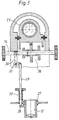
- Fig. 3
- einen Längsschnitt durch ein Getriebe in einer zweiten Ausführungsform.
- Fig. 1
- 2 shows a longitudinal section through the telescope according to the invention in a first embodiment,
- Fig. 2
- a cross section with details of the transmission of FIG. 1 and
- Fig. 3
- a longitudinal section through a transmission in a second embodiment.
Das in Fig. 1 dargestellte monokulare Fernrohr weist einen hier verkürzt gezeichneten Tubus 10 auf, der ein Objektiv 11 trägt. Ein diesem gegenüberliegendes Okular ist als Wechselokular 12 ausgebildet, mit dem die Vergrößerung wählbar ist. Das Wechselokular 12 kann als Variookular mit stufenlos veränderbarer Vergrößerung, beispielsweise von 20-60fach ausgebildet sein, oder es können einzelne Okulare unterschiedlicher Vergrößerung, beispielsweise 20-, 40- und 60fach, verwendet werden. Zur Scharfstellung ist eine Fokussiereinheit 13 aus einem Linsensystem vorgesehen, die mittels eines Stellgliedes 14 entlang der optischen Achse 15 des Fernrohrs verschiebbar ist. Das Stellglied 14 trägt an beiden Enden Rändelknöpfe 16. Weiterhin ist im Tubus 10 zur Umlenkung des Strahlenganges zwischen der Fokussiereinheit 13 und dem Wechselokular 12 ein Prismensatz 17 befestigt. Das Stellglied 14 ist als Übersetzungsgetriebe 18 ausgebildet, das in Fig. 1 nur schematisch gezeigt ist.The monocular telescope shown in FIG. 1 has a
In Fig. 2 ist die Ausbildung des Übersetzungsgetriebes 18 in einer ersten Ausführungsform dargestellt. Auf dem als Drehachse mit einem Rastgesperre aus Rastkerben 19, Feder 20 und Kugel 21 ausgebildeten Stellglied 14 sind Zahnräder 22,22',22'' unterschiedlichen Durchmessers montiert. Oberhalb des Stellglieds 14 ist ein Schlitten 23 längs der optischen Achse 15 in Führungsbahnen 24 verschiebbar, der die Fokussiereinheit 13 trägt. An seiner Unterseite weist der Schlitten 23 Zahnstangen 25,25',25'' auf, die durch Herausziehen bzw. Eindrücken des Stellgliedes 14 in Eingriff mit den entsprechenden Zahnrädern 22,22',22'' bringbar sind. Entsprechend der Vergrößerung des verwendeten Wechselokulars 12 ist die Stellgeschwindigkeit für die Scharfstellung mittels des Übersetzungsgetriebes in drei Stufen angepaßt.2 shows the design of the
Die in Fig. 3 gezeigte Ausführungsform unterscheidet sich von derjenigen gem. Fig. 2 dadurch, daß hier ein Übersetzungsgetriebe 26 verwendet ist, das mit dem jeweiligen Wechselokular 12 getrieblich verbunden ist. Dadurch wird erreicht, daß beim Wechsel des Okulars 12 die dessen Vergrößerung entsprechende Stellgeschwindigkeit für die Scharfstellung selbsttätig angepaßt wird. Das Wechselokular 12 ist am Fernrohr mittels eines Bajonetts 27 befestigbar, das hier einen Bund 28 aufweist, dessen axiale Tiefe je nach Vergrößerung variiert. An dem Bund 28 liegt ein Ende eines Steuerstifts 29 an, dessen anderes Ende mit einem Winkelhebel 30 verbunden ist. Dieser ist um eine Achse 31 schwenkbar und greift am Stellglied 14 an. Unter dem Druck einer Feder 32 wird der Steuerstift 29 je nach Lage des Bundes 28 am Bajonett 27 axial verschoben, wobei der Winkelhebel 30 diese Bewegung in eine dazu senkrechte Verschiebung des Stellglieds 14 übersetzt.Das auf demselben angeordnete Übersetzungsgetriebe 26 nebst Schlitten 23 entspricht im wesentlichen demjenigen von Fig.. 2, weswegen die gleichen Bezugszeichen verwendet sind.The embodiment shown in Fig. 3 differs from that according to. Fig. 2 in that a
Es versteht sich, daß zahlreiche Variationen des Beschriebenen möglich sind. So kann bei einem Wechselokular mit veränderlicher Vergrößerung anstatt eines Bundes eine Steuerkurve angeformt sein, an welcher der Steuerstift anliegt.It is understood that numerous variations of what has been described are possible. In the case of an interchangeable eyepiece with variable magnification, instead of a collar, a control curve can be formed on which the control pin rests.
Bei einer nur für zwei unterschiedliche Vergrößerungen ausgelegten Anordnung kann ein koaxialer Grob-Feintrieb Verwendung finden, wie er an sich zur Scharfeinstellung besonders bei Mikroskopen bekannt ist. Weiterhin kann die manuelle Verstellung durch eine motorische ersetzt sein, wobei anstelle der Rändelknöpfe ein Bedienungsknopf vorgesehen ist. Schließlich kann auch das Fokussierelement anders ausgebildet sein, beispielsweise als Prismensatz. Dieser kann auf einer Zahnstange montiert sein, welche mittels eines auf dem Stellglied befestigten Zahnrades axial bewegt wird.In the case of an arrangement designed only for two different magnifications, a coaxial coarse fine drive can be used, as is known per se, in particular for microscopes, for focusing. Furthermore, the manual adjustment can be replaced by a motorized one, an operating button being provided instead of the knurled buttons. Finally, the focusing element can be different be formed, for example as a prism set. This can be mounted on a toothed rack which is moved axially by means of a toothed wheel attached to the actuator.
Claims (6)
- Monocular telescope of constant length with an objective (11) arranged in a tube (10), an exchangeable and/or a variable eyepiece (12) for varying the magnification and a focussing unit which is displaceable in the tube by means of a setting member (14), characterised thereby, that for adaptation of the setting speed of the focussing unit (13) to the chosen magnification, the setting member (14) is constructed as transmission gear (18, 26) with several different transmission ratios which are selectable according to the selected magnification used, wherein a smaller transmission ratio is selectable in conjunction with a high magnification and conversely.
- Monocular telescope according to claim 1, characterised thereby, that gear wheels (22, 22', 22") of different diameters are mounted on the setting member (14) and bringable into engagement with toothed racks (25, 25', 25"), which are fastened at a sliding carriage (23) carrying the focussing unit (13), by displacement of the setting member (14) transversely to the optical axis (15).
- Monocular telescope according to claim 1, characterised thereby, that the setting member (14) is connected in geared manner with the eyepiece (12) in such a manner that an automatic switching-over of the transmission gear (18, 26) takes place by displacement of the setting member (14) on a change in magnification.
- Monocular telescope according to claim 3, characterised thereby, that the eyepiece (12) is provided with a colalr (28), the axial depth of which varies in accordance with the magnification, one end of a control pin (29) lies against the collar (28) and the other end of the control pin (29) is connected with an angle lever (30), which is pivotable about an axis (31) and engages at the setting member (14), wherein the control pin (29) is displaced axially in accordance with the position of the collar (28) and the angle lever (30) translates this movement into a displacement of the setting member (14).
- Monocular telescope according to claim 1, characterised thereby, that a lens system is provided as focussing unit (13).
- Monocular telescope according to claim 1, characterised thereby, that a prism system is provided as focussing unit (13).
Applications Claiming Priority (2)
| Application Number | Priority Date | Filing Date | Title |
|---|---|---|---|
| DE4231655A DE4231655C5 (en) | 1992-09-22 | 1992-09-22 | Monocular telescope of constant length |
| DE4231655 | 1992-09-22 |
Publications (3)
| Publication Number | Publication Date |
|---|---|
| EP0589177A2 EP0589177A2 (en) | 1994-03-30 |
| EP0589177A3 EP0589177A3 (en) | 1994-05-18 |
| EP0589177B1 true EP0589177B1 (en) | 1996-04-24 |
Family
ID=6468517
Family Applications (1)
| Application Number | Title | Priority Date | Filing Date |
|---|---|---|---|
| EP93112019A Expired - Lifetime EP0589177B1 (en) | 1992-09-22 | 1993-07-28 | Monocular telescope having constant length |
Country Status (8)
| Country | Link |
|---|---|
| US (1) | US5453875A (en) |
| EP (1) | EP0589177B1 (en) |
| JP (1) | JP2759046B2 (en) |
| KR (1) | KR940007553A (en) |
| AT (1) | ATE137343T1 (en) |
| DE (1) | DE4231655C5 (en) |
| HK (1) | HK173496A (en) |
| SG (1) | SG47550A1 (en) |
Families Citing this family (8)
| Publication number | Priority date | Publication date | Assignee | Title |
|---|---|---|---|---|
| DE10218171A1 (en) * | 2001-04-27 | 2002-10-31 | Hensoldt & Soehne Optik | Focusing mechanism, for a monocular telescope, has coarse and fine setting drives with displaced controls and belt drives to the focusing optics, giving a rapid coarse setting and a fine adjustment |
| EP1355183A3 (en) * | 2002-04-16 | 2005-02-16 | Hensoldt AG | Telescope |
| CN100430772C (en) * | 2006-02-15 | 2008-11-05 | 亚洲光学股份有限公司 | Optical axis regulating mechanism and optical observing device with opticaxis regulating mechanism |
| US7359114B2 (en) * | 2006-06-13 | 2008-04-15 | Litton Systems, Inc. | Clip-on night vision device |
| AT510937B1 (en) * | 2010-12-23 | 2021-02-15 | Swarovski Optik Kg | MODULAR TELESCOPE |
| AT510935B1 (en) * | 2010-12-23 | 2021-02-15 | Swarovski Optik Kg | TELESCOPE WITH LENS AND EYEPIECE MODULE |
| AT510936B1 (en) * | 2010-12-23 | 2021-02-15 | Swarovski Optik Kg | TELESCOPE WITH CONNECTABLE MODULES |
| DE102011000404B4 (en) * | 2011-01-28 | 2012-10-25 | Schmidt & Bender Gmbh & Co. Kg | Reversing system with split sleeve in gate shape |
Family Cites Families (8)
| Publication number | Priority date | Publication date | Assignee | Title |
|---|---|---|---|---|
| US1088494A (en) * | 1913-10-08 | 1914-02-24 | Kirtland Bros & Co | Multifocal telescope. |
| DE1109398B (en) * | 1958-11-22 | 1961-06-22 | Hertel & Reuss | Telescope with changeable magnification |
| US3028792A (en) * | 1960-07-21 | 1962-04-10 | Bausch & Lomb | Variable power spotting telescope |
| DE1243405B (en) * | 1964-12-22 | 1967-06-29 | Ertel Werk Feinmechanik | Geodetic rifle scope |
| CH499119A (en) * | 1969-04-28 | 1970-11-15 | Zeiss Jena Veb Carl | Focusing device for optical devices, in particular telescopes |
| JPS54133355A (en) * | 1978-04-07 | 1979-10-17 | Nippon Chemical Ind | Erect type zoom telephoto optical system |
| JPS56162728A (en) * | 1980-05-20 | 1981-12-14 | Minolta Camera Co Ltd | Automatic focusing device of zoom lens |
| US4600277A (en) * | 1984-02-13 | 1986-07-15 | Murray Jr Joseph E | Telescope with multiple image-viewing assemblies |
-
1992
- 1992-09-22 DE DE4231655A patent/DE4231655C5/en not_active Expired - Fee Related
-
1993
- 1993-07-28 SG SG1996002796A patent/SG47550A1/en unknown
- 1993-07-28 AT AT93112019T patent/ATE137343T1/en not_active IP Right Cessation
- 1993-07-28 EP EP93112019A patent/EP0589177B1/en not_active Expired - Lifetime
- 1993-09-15 US US08/120,819 patent/US5453875A/en not_active Expired - Lifetime
- 1993-09-17 JP JP5231523A patent/JP2759046B2/en not_active Expired - Fee Related
- 1993-09-22 KR KR1019930019643A patent/KR940007553A/en not_active Application Discontinuation
-
1996
- 1996-09-12 HK HK173496A patent/HK173496A/en not_active IP Right Cessation
Non-Patent Citations (1)
| Title |
|---|
| Sov. J. Opt. Technol., Vol. 43, No. 6, June 1976, P. 360-361, B. L. Nefedov et al. : "Telescope with two magnifications" * |
Also Published As
| Publication number | Publication date |
|---|---|
| JPH06194558A (en) | 1994-07-15 |
| JP2759046B2 (en) | 1998-05-28 |
| DE4231655C1 (en) | 1993-11-18 |
| EP0589177A3 (en) | 1994-05-18 |
| DE4231655C5 (en) | 2006-01-26 |
| HK173496A (en) | 1996-09-20 |
| EP0589177A2 (en) | 1994-03-30 |
| US5453875A (en) | 1995-09-26 |
| ATE137343T1 (en) | 1996-05-15 |
| SG47550A1 (en) | 1998-04-17 |
| KR940007553A (en) | 1994-04-27 |
Similar Documents
| Publication | Publication Date | Title |
|---|---|---|
| EP1598690B1 (en) | Focussing arrangement with diopter adjustment for binocular telescopes | |
| DE2654778A1 (en) | STEREOSCOPIC MICROSCOPE TUBE | |
| EP0589177B1 (en) | Monocular telescope having constant length | |
| EP0961147B1 (en) | Binocular telescope | |
| EP0364794B1 (en) | Illumination device for an operation microscope | |
| DE2715646A1 (en) | ADJUSTMENT DEVICE FOR FOCUSING LENSES | |
| DE4033151C2 (en) | Binocular binoculars | |
| EP0055209B1 (en) | Beam folding device | |
| DE19528041C1 (en) | Focusing drive for the microscope stage | |
| DE3321050A1 (en) | OPTICAL DEVICE, IN PARTICULAR MICROSCOPE | |
| DE3128642A1 (en) | Zoom (varifocal) lens assembly | |
| EP2745159A1 (en) | Adjustment device on an optical unit | |
| EP1460467A2 (en) | Tube for adapting to a microscope | |
| WO2001018584A1 (en) | Variable lens | |
| DE2627486A1 (en) | COARSE AND FINE ADJUSTMENT GEAR FOR MICROSCOPES WITH AUTOMATIC FOCUSING | |
| DE8003643U1 (en) | ADJUSTING DEVICE FOR A PANCRATIC LENS OF A STEREOMICROSCOPE | |
| DE2736101C2 (en) | ||
| DE2721017B2 (en) | Lens mount for a camera | |
| DE3604029C1 (en) | Feed device for the specimen holder of a travelling microtome | |
| DE4035707C2 (en) | Binocular adjustment mechanism | |
| DE102005062229A1 (en) | Arrangement for adjusting optical units or components and/or lens groups e.g., in vario-imaging systems, has optical units or components movable relative to one another along optical axis of imaging system | |
| DE8428377U1 (en) | ZOOM LENS CAPTURE | |
| WO2002088820A2 (en) | Rough and fine drive comprising a belt drive for a monocular, especially for a telescope | |
| DE4331650A1 (en) | Objective (lens) with differential gear (differential mechanism) | |
| DE2259723C3 (en) | Adjustment device for varifocal lenses with extremely large focal length nberelch |
Legal Events
| Date | Code | Title | Description |
|---|---|---|---|
| PUAI | Public reference made under article 153(3) epc to a published international application that has entered the european phase |
Free format text: ORIGINAL CODE: 0009012 |
|
| AK | Designated contracting states |
Kind code of ref document: A2 Designated state(s): AT CH FR GB LI |
|
| PUAL | Search report despatched |
Free format text: ORIGINAL CODE: 0009013 |
|
| AK | Designated contracting states |
Kind code of ref document: A3 Designated state(s): AT CH FR GB LI |
|
| 17P | Request for examination filed |
Effective date: 19940707 |
|
| 17Q | First examination report despatched |
Effective date: 19940817 |
|
| GRAH | Despatch of communication of intention to grant a patent |
Free format text: ORIGINAL CODE: EPIDOS IGRA |
|
| GRAA | (expected) grant |
Free format text: ORIGINAL CODE: 0009210 |
|
| AK | Designated contracting states |
Kind code of ref document: B1 Designated state(s): AT CH FR GB LI |
|
| REF | Corresponds to: |
Ref document number: 137343 Country of ref document: AT Date of ref document: 19960515 Kind code of ref document: T |
|
| GBT | Gb: translation of ep patent filed (gb section 77(6)(a)/1977) |
Effective date: 19960514 |
|
| ET | Fr: translation filed | ||
| PLBE | No opposition filed within time limit |
Free format text: ORIGINAL CODE: 0009261 |
|
| STAA | Information on the status of an ep patent application or granted ep patent |
Free format text: STATUS: NO OPPOSITION FILED WITHIN TIME LIMIT |
|
| 26N | No opposition filed | ||
| REG | Reference to a national code |
Ref country code: GB Ref legal event code: IF02 |
|
| PGFP | Annual fee paid to national office [announced via postgrant information from national office to epo] |
Ref country code: CH Payment date: 20070713 Year of fee payment: 15 Ref country code: AT Payment date: 20070716 Year of fee payment: 15 |
|
| PGFP | Annual fee paid to national office [announced via postgrant information from national office to epo] |
Ref country code: GB Payment date: 20070720 Year of fee payment: 15 |
|
| PGFP | Annual fee paid to national office [announced via postgrant information from national office to epo] |
Ref country code: FR Payment date: 20070710 Year of fee payment: 15 |
|
| REG | Reference to a national code |
Ref country code: CH Ref legal event code: PL |
|
| GBPC | Gb: european patent ceased through non-payment of renewal fee |
Effective date: 20080728 |
|
| PG25 | Lapsed in a contracting state [announced via postgrant information from national office to epo] |
Ref country code: AT Free format text: LAPSE BECAUSE OF NON-PAYMENT OF DUE FEES Effective date: 20080728 |
|
| REG | Reference to a national code |
Ref country code: FR Ref legal event code: ST Effective date: 20090331 |
|
| PG25 | Lapsed in a contracting state [announced via postgrant information from national office to epo] |
Ref country code: LI Free format text: LAPSE BECAUSE OF NON-PAYMENT OF DUE FEES Effective date: 20080731 Ref country code: GB Free format text: LAPSE BECAUSE OF NON-PAYMENT OF DUE FEES Effective date: 20080728 Ref country code: CH Free format text: LAPSE BECAUSE OF NON-PAYMENT OF DUE FEES Effective date: 20080731 |
|
| PG25 | Lapsed in a contracting state [announced via postgrant information from national office to epo] |
Ref country code: FR Free format text: LAPSE BECAUSE OF NON-PAYMENT OF DUE FEES Effective date: 20080731 |