EP0589149B1 - Carburettor needle valve adjustment limiter cap - Google Patents
Carburettor needle valve adjustment limiter cap Download PDFInfo
- Publication number
- EP0589149B1 EP0589149B1 EP19930109852 EP93109852A EP0589149B1 EP 0589149 B1 EP0589149 B1 EP 0589149B1 EP 19930109852 EP19930109852 EP 19930109852 EP 93109852 A EP93109852 A EP 93109852A EP 0589149 B1 EP0589149 B1 EP 0589149B1
- Authority
- EP
- European Patent Office
- Prior art keywords
- cap
- shank
- valve
- carburetor
- arm
- Prior art date
- Legal status (The legal status is an assumption and is not a legal conclusion. Google has not performed a legal analysis and makes no representation as to the accuracy of the status listed.)
- Expired - Lifetime
Links
- 239000000446 fuel Substances 0.000 claims description 33
- 239000000463 material Substances 0.000 claims description 6
- 239000004033 plastic Substances 0.000 claims description 2
- 229920003023 plastic Polymers 0.000 claims description 2
- 230000000717 retained effect Effects 0.000 description 8
- 238000010276 construction Methods 0.000 description 5
- 238000003780 insertion Methods 0.000 description 4
- 230000037431 insertion Effects 0.000 description 4
- 238000012360 testing method Methods 0.000 description 4
- 238000013021 overheating Methods 0.000 description 3
- 230000002093 peripheral effect Effects 0.000 description 3
- 239000004677 Nylon Substances 0.000 description 2
- 238000002485 combustion reaction Methods 0.000 description 2
- 238000009472 formulation Methods 0.000 description 2
- 238000004519 manufacturing process Methods 0.000 description 2
- 238000000034 method Methods 0.000 description 2
- 239000000203 mixture Substances 0.000 description 2
- 229920001778 nylon Polymers 0.000 description 2
- UGFAIRIUMAVXCW-UHFFFAOYSA-N Carbon monoxide Chemical compound [O+]#[C-] UGFAIRIUMAVXCW-UHFFFAOYSA-N 0.000 description 1
- 229920004943 Delrin® Polymers 0.000 description 1
- 241000196324 Embryophyta Species 0.000 description 1
- 229920006068 Minlon® Polymers 0.000 description 1
- 239000004957 Zytel Substances 0.000 description 1
- 229920006102 Zytel® Polymers 0.000 description 1
- 230000004323 axial length Effects 0.000 description 1
- 229910002091 carbon monoxide Inorganic materials 0.000 description 1
- 238000004891 communication Methods 0.000 description 1
- 230000000295 complement effect Effects 0.000 description 1
- 238000011161 development Methods 0.000 description 1
- 230000018109 developmental process Effects 0.000 description 1
- 229920001971 elastomer Polymers 0.000 description 1
- 229930195733 hydrocarbon Natural products 0.000 description 1
- 150000002430 hydrocarbons Chemical class 0.000 description 1
- 238000007373 indentation Methods 0.000 description 1
- 238000009434 installation Methods 0.000 description 1
- 230000002452 interceptive effect Effects 0.000 description 1
- 238000005461 lubrication Methods 0.000 description 1
- ISWSIDIOOBJBQZ-UHFFFAOYSA-N phenol group Chemical group C1(=CC=CC=C1)O ISWSIDIOOBJBQZ-UHFFFAOYSA-N 0.000 description 1
- 229920006324 polyoxymethylene Polymers 0.000 description 1
- 229920002635 polyurethane Polymers 0.000 description 1
- 239000004814 polyurethane Substances 0.000 description 1
- 229920001169 thermoplastic Polymers 0.000 description 1
- 239000012815 thermoplastic material Substances 0.000 description 1
- 239000004416 thermosoftening plastic Substances 0.000 description 1
Images


Classifications
-
- F—MECHANICAL ENGINEERING; LIGHTING; HEATING; WEAPONS; BLASTING
- F16—ENGINEERING ELEMENTS AND UNITS; GENERAL MEASURES FOR PRODUCING AND MAINTAINING EFFECTIVE FUNCTIONING OF MACHINES OR INSTALLATIONS; THERMAL INSULATION IN GENERAL
- F16B—DEVICES FOR FASTENING OR SECURING CONSTRUCTIONAL ELEMENTS OR MACHINE PARTS TOGETHER, e.g. NAILS, BOLTS, CIRCLIPS, CLAMPS, CLIPS OR WEDGES; JOINTS OR JOINTING
- F16B41/00—Measures against loss of bolts, nuts, or pins; Measures against unauthorised operation of bolts, nuts or pins
- F16B41/005—Measures against unauthorised operation of bolts, nuts or pins
-
- F—MECHANICAL ENGINEERING; LIGHTING; HEATING; WEAPONS; BLASTING
- F02—COMBUSTION ENGINES; HOT-GAS OR COMBUSTION-PRODUCT ENGINE PLANTS
- F02B—INTERNAL-COMBUSTION PISTON ENGINES; COMBUSTION ENGINES IN GENERAL
- F02B63/00—Adaptations of engines for driving pumps, hand-held tools or electric generators; Portable combinations of engines with engine-driven devices
- F02B63/02—Adaptations of engines for driving pumps, hand-held tools or electric generators; Portable combinations of engines with engine-driven devices for hand-held tools
-
- F—MECHANICAL ENGINEERING; LIGHTING; HEATING; WEAPONS; BLASTING
- F02—COMBUSTION ENGINES; HOT-GAS OR COMBUSTION-PRODUCT ENGINE PLANTS
- F02M—SUPPLYING COMBUSTION ENGINES IN GENERAL WITH COMBUSTIBLE MIXTURES OR CONSTITUENTS THEREOF
- F02M19/00—Details, component parts, or accessories of carburettors, not provided for in, or of interest apart from, the apparatus of groups F02M1/00 - F02M17/00
- F02M19/04—Fuel-metering pins or needles
-
- F—MECHANICAL ENGINEERING; LIGHTING; HEATING; WEAPONS; BLASTING
- F02—COMBUSTION ENGINES; HOT-GAS OR COMBUSTION-PRODUCT ENGINE PLANTS
- F02M—SUPPLYING COMBUSTION ENGINES IN GENERAL WITH COMBUSTIBLE MIXTURES OR CONSTITUENTS THEREOF
- F02M3/00—Idling devices for carburettors
- F02M3/08—Other details of idling devices
- F02M3/10—Fuel metering pins; Nozzles
-
- F—MECHANICAL ENGINEERING; LIGHTING; HEATING; WEAPONS; BLASTING
- F02—COMBUSTION ENGINES; HOT-GAS OR COMBUSTION-PRODUCT ENGINE PLANTS
- F02B—INTERNAL-COMBUSTION PISTON ENGINES; COMBUSTION ENGINES IN GENERAL
- F02B1/00—Engines characterised by fuel-air mixture compression
- F02B1/02—Engines characterised by fuel-air mixture compression with positive ignition
- F02B1/04—Engines characterised by fuel-air mixture compression with positive ignition with fuel-air mixture admission into cylinder
-
- F—MECHANICAL ENGINEERING; LIGHTING; HEATING; WEAPONS; BLASTING
- F02—COMBUSTION ENGINES; HOT-GAS OR COMBUSTION-PRODUCT ENGINE PLANTS
- F02B—INTERNAL-COMBUSTION PISTON ENGINES; COMBUSTION ENGINES IN GENERAL
- F02B75/00—Other engines
- F02B75/02—Engines characterised by their cycles, e.g. six-stroke
- F02B2075/022—Engines characterised by their cycles, e.g. six-stroke having less than six strokes per cycle
- F02B2075/025—Engines characterised by their cycles, e.g. six-stroke having less than six strokes per cycle two
-
- F—MECHANICAL ENGINEERING; LIGHTING; HEATING; WEAPONS; BLASTING
- F02—COMBUSTION ENGINES; HOT-GAS OR COMBUSTION-PRODUCT ENGINE PLANTS
- F02M—SUPPLYING COMBUSTION ENGINES IN GENERAL WITH COMBUSTIBLE MIXTURES OR CONSTITUENTS THEREOF
- F02M3/00—Idling devices for carburettors
- F02M3/08—Other details of idling devices
- F02M3/10—Fuel metering pins; Nozzles
- F02M2003/105—Needle adjustment limiter caps
-
- F—MECHANICAL ENGINEERING; LIGHTING; HEATING; WEAPONS; BLASTING
- F05—INDEXING SCHEMES RELATING TO ENGINES OR PUMPS IN VARIOUS SUBCLASSES OF CLASSES F01-F04
- F05C—INDEXING SCHEME RELATING TO MATERIALS, MATERIAL PROPERTIES OR MATERIAL CHARACTERISTICS FOR MACHINES, ENGINES OR PUMPS OTHER THAN NON-POSITIVE-DISPLACEMENT MACHINES OR ENGINES
- F05C2201/00—Metals
- F05C2201/02—Light metals
- F05C2201/021—Aluminium
-
- F—MECHANICAL ENGINEERING; LIGHTING; HEATING; WEAPONS; BLASTING
- F16—ENGINEERING ELEMENTS AND UNITS; GENERAL MEASURES FOR PRODUCING AND MAINTAINING EFFECTIVE FUNCTIONING OF MACHINES OR INSTALLATIONS; THERMAL INSULATION IN GENERAL
- F16B—DEVICES FOR FASTENING OR SECURING CONSTRUCTIONAL ELEMENTS OR MACHINE PARTS TOGETHER, e.g. NAILS, BOLTS, CIRCLIPS, CLAMPS, CLIPS OR WEDGES; JOINTS OR JOINTING
- F16B37/00—Nuts or like thread-engaging members
- F16B37/14—Cap nuts; Nut caps or bolt caps
-
- Y—GENERAL TAGGING OF NEW TECHNOLOGICAL DEVELOPMENTS; GENERAL TAGGING OF CROSS-SECTIONAL TECHNOLOGIES SPANNING OVER SEVERAL SECTIONS OF THE IPC; TECHNICAL SUBJECTS COVERED BY FORMER USPC CROSS-REFERENCE ART COLLECTIONS [XRACs] AND DIGESTS
- Y10—TECHNICAL SUBJECTS COVERED BY FORMER USPC
- Y10S—TECHNICAL SUBJECTS COVERED BY FORMER USPC CROSS-REFERENCE ART COLLECTIONS [XRACs] AND DIGESTS
- Y10S261/00—Gas and liquid contact apparatus
- Y10S261/38—Needle valves
-
- Y—GENERAL TAGGING OF NEW TECHNOLOGICAL DEVELOPMENTS; GENERAL TAGGING OF CROSS-SECTIONAL TECHNOLOGIES SPANNING OVER SEVERAL SECTIONS OF THE IPC; TECHNICAL SUBJECTS COVERED BY FORMER USPC CROSS-REFERENCE ART COLLECTIONS [XRACs] AND DIGESTS
- Y10—TECHNICAL SUBJECTS COVERED BY FORMER USPC
- Y10S—TECHNICAL SUBJECTS COVERED BY FORMER USPC CROSS-REFERENCE ART COLLECTIONS [XRACs] AND DIGESTS
- Y10S261/00—Gas and liquid contact apparatus
- Y10S261/84—Tamperproof
-
- Y—GENERAL TAGGING OF NEW TECHNOLOGICAL DEVELOPMENTS; GENERAL TAGGING OF CROSS-SECTIONAL TECHNOLOGIES SPANNING OVER SEVERAL SECTIONS OF THE IPC; TECHNICAL SUBJECTS COVERED BY FORMER USPC CROSS-REFERENCE ART COLLECTIONS [XRACs] AND DIGESTS
- Y10—TECHNICAL SUBJECTS COVERED BY FORMER USPC
- Y10T—TECHNICAL SUBJECTS COVERED BY FORMER US CLASSIFICATION
- Y10T137/00—Fluid handling
- Y10T137/6851—With casing, support, protector or static constructional installations
- Y10T137/7043—Guards and shields
- Y10T137/7062—Valve guards
Definitions
- This invention relates to carburetors for internal combustion engines and more particularly to a cap for tamper-proof limiting of fuel flow in a carburetor.
- carburetor limiter caps have been used to restrict carburetor fuel flow metering valve adjustment to prevent the excessive emission of carbon monoxide and unburned hydrocarbons from internal combustion engines.
- limiters have been used with conventional float bowl carburetors to control automobile exhaust emissions. More recently their use has been extended to diaphragm-type carburetors in small engines simply to prevent gross misadjustment of fuel flow.
- future emissions regulations are expected to extend the role of limiter caps to control engine emissions.
- Fuel flow within a carburetor is commonly metered during no load or idle engine operation by a first "idle" needle valve and during part or full load operation by a second "main” needle valve.
- each valve has a threaded cylindrical body with an enlarged knurled head at one end and a conical or needle shaped valve control surface at the opposite end which is received within an opening in the carburetor body.
- each valve is rotatively adjusted to axially extend or retract the valve control surface within a fuel passage in the carburetor until optimum fuel flow through the passage is achieved. Pre-calibration of the carburetor on a flow test bench may be performed prior to being assembled to an engine.
- limiter caps generally consist of a cylindrical body having an opening at one end for axially receiving the valve head in tight fitting engagement to prevent removal and promote rotation of both in unison.
- a recess in the opposite end of the cap is provided to enable an adjustment tool to engage the valve directly or the cap alone to rotate both in unison to make fuel flow adjustments.
- Projecting radially outwardly from the cap body is an arm for abutting against a fixed stop extending from the carburetor to limit valve rotation.
- Representative limiter caps are described in US-A-3,618,906 and 5,055,238.
- Stop members such as an integrally cast projection of the carburetor or the body of another cap press-fit on an adjacent needle valve may be used to limit valve and cap rotation and hence adjustment.
- Japanese Patent Publication Jitsuko Sho 61-13455 discloses a hollow cylindrical collar limiter which has an outwardly extending arm for abutting directly against the head of an adjacent valve to limit adjustment.
- a two-stroke engine is sold with the adjustment range incorrectly set, subsequent user adjustment could increase emissions or deprive the engine of lubrication entrained in the fuel flow leading to overheating or even catastrophic failure.
- a user or operator of the power tool may lack the necessary range of fuel flow adjustment to keep the engine efficiently operating under the full range of temperature, humidity, altitude or other engine operating conditions which may be encountered.
- a cap for tamper-proof limiting of adjustment of fuel flow in a carburetor as defined in the preamble of claim 1 has become known from FR-A-2,291,362.
- the cap construction disclosed therein has only first and second positions. In the first position, the cap is releasably engageable with the head of the shank for rotating the shank and, in the second position, the cap rotates freely relative to the shank to avoid further adjustment of the valve shank unless and until the cap is returned to the first position. The cap can be repeatedly removed between these first and second positions.
- cap has become known from document "REVUE TECHNIQUE AUTOMOBILE” Vol. 32, No. 372, pp. 136, 137.
- the cap disclosed therein has a radial arm engageable with a stop.
- the cap is movable to a first position releasably engaging the head of the shank for adjusting the valve of the carburetor and to a second position in which the cap is retained on the shank and is rotatable relative to the shank so that the carburetor cannot be further adjusted.
- a cap for limiting the range of adjustment of a fuel flow metering valve in a carburetor has a body with a passage for telescopically axially receiving the head end of a shank of the metering valve therein. At the free end, the cap may have a face with a recess or opening therein for receiving an adjustment tool to rotate the cap, valve or both.
- An arm projects generally radially outwardly from the body to abut against a stop carried by or operably associated with the carburetor to limit valve rotation and hence adjustment.
- the cap has a retainer which retains the cap on the valve shank in a first position while allowing the cap to freely rotate relative to the valve.
- the cap is axially movable on the shank to a second position where a portion in the passage firmly engages the shank so that the cap and valve rotate only in unison to thereby limit adjustment of the valve by the arm engaging a stop.
- the cap is movable to a third position in which a drive portion releasably engages the shank for rotating the shank to adjust the valve before the cap is moved to the second position to limit further adjustment of the valve.
- the cap is locked in the second position to prevent removal of the cap from the shank to thereby insure continuous or tamper proof limiting of further adjustment of the valve.
- a cam portion in the passage facilitates movement of the cap to the second position.
- the cap In typical use, the cap is pressed onto the valve shank to a first position where it is retained on the shank and can rotate freely relative to the valve. On the shank, it may be moved from this position to releasably engage the valve for adjusting fuel flow.
- the limiter arm is angularly or circumferentially positioned on the valve to provide the desired limits of user fuel flow adjustment. Once the arm is properly oriented, the cap is further pressed axially inwardly to a second position securing the cap to the valve in tight engagement therewith so the cap and valve can rotate only in unison. Any subsequent rotational adjustment of the valve is limited in either direction by the limiter arm striking a stop carried by or operably associated with the carburetor.
- An object of the limiter cap of this invention is to restrict adjustment of a valve to prevent excessive engine exhaust emissions and engine overheating or failure.
- Another object is to facilitate quick and easy assembly of the cap to a needle valve of a carburetor body and final calibration of the carburetor while operating on an engine without requiring the removal of the grommet and engine shroud after final carburetor calibration.
- this limiter cap may be installed after initial calibration of an assembled carburetor on a flow test bench and prior to performing final calibration of the carburetor on an engine.
- a further object of the present invention is that it allows assembly of the limiter cap onto a needle valve of the carburetor to enable rotational adjustment of each valve during carburetor calibration, simple and accurate positioning of the arm of each cap relative to the final adjusted position of the valve and carburetor stops, and easy assembly of the cap into secure locking engagement with the valve to allow rotation of the cap and valve only in unison while limiting rotational adjustment of the valve in either direction.
- Another object of this cap is to allow limited fuel flow adjustment to enable a user of an engine powered tool to adequately adjust carburetor performance to fine tune engine operation under a variety of operating conditions while preventing fuel flow overadjustment possibly causing excessive exhaust gas emissions or engine overheating.
- a still further advantage of this invention is that it allows quick and easy limiter arm orientation when mounted in a freely rotating position on the valve to expediently, yet accurately, fix the allowable range of valve rotation.
- FIGS. 1 & 1A illustrate a typical assembly of a hand-held power tool 30 such as a hedge trimmer with a two-stroke gasoline engine 32 having a carburetor 34 with idle 36 and main 38 needle valves and limiter caps 40, 42 of this invention.
- the idle 36 and main 38 valves meter fuel flow during low speed and high speed engine operation respectively.
- the carburetor 34 has an air inlet 44 attached to an air cleaner 46 and an outlet 48 in communication with an intake manifold 50 of the engine 32.
- the engine 32 and carburetor 34 are enclosed by a housing or shroud 52 with a grommet 54 having a pair of access openings 56 axially aligned with each cap 40, 42 to enable limited valve adjustment while preventing tampering with or removal of either cap.
- each valve 36, 38 has an elongated generally cylindrical shank 60 with a head 62 at one end and a generally conical valve control surface 64 at the other end.
- the shank 60 has a plurality of threads 66 about its outer periphery to engage with complementary threads (not shown) within the carburetor body to enable secure insertion of the valve 36 therein and axial adjustment of the needle valve 36 within a fuel flow passage.
- a recess or slot 68 is provided in the free end of the valve 36 for receiving an adjustment tool, such as the blade of a screwdriver, for facilitating rotational adjustment of the valve 36.
- an adjustment tool such as the blade of a screwdriver
- a plurality of axial ridges or knurls 70 in the outer peripheral surface of the head 62 may be engaged by a tool or manually for adjustment. Unintentional valve rotation during engine vibration is prevented by a spring 72 received over the valve shank 60 and disposed between the carburetor body 34 and a flange 74 on the valve shank 60 adjacent the head 62.
- each needle valve 36, 38 is separated into a first segment or shoulder 76 at the end of the valve and a second segment 78 adjacent the spring retaining flange 74 by a circumferentially continuous groove 80.
- the head segments 76, 78 may also be knurled with axially extending flutes.
- Each cap 40, 42 has a body 82 with an arm 84 projecting therefrom for limiting valve rotation and hence adjustment. The location of the arm 84, 84' on the body is the only difference between these caps.
- the body 82 has a passage 86 therein.
- Portions within the passage 86 enable the cap 40 to be carried on a valve 36 in a freely rotating first position during assembly and limiter arm 84 orientation, in a second position securing the cap 40 to the valve 36 to limit adjustment and maintain emissions calibration, and in a third position to releasably drivingly engage the valve 36 to perform fuel flow adjustment.
- the body 82 also has a generally slotted recess 88 in the face of the free end of the cap 40 for receiving an adjustment tool therein.
- the limiter arm 84 is an arcuate flanged projection which extends generally radially outwardly from the body 82 for abutting against a stop 90 carried by or operably associated with the carburetor to limit rotation to less than a complete revolution.
- the stop may be an adjacent valve shank, a cap mounted thereon (FIG. 7) 90, a fixed stop 90' projecting from the carburetor body (FIG. 8), a projection extending from the housing 52, grommet 54, or engine 32 (not shown), or the like.
- the arm 84 is set axially back from the cap face to allow adjustment without the surrounding grommet 54 objectionably interfering with the arm 84.
- the arm 84 may be located anywhere along the axial length of the body 82.
- the angle subtended by the flange arm 84 is sufficient to limit the extent to which the valve 36 can be rotated to fine tune the engine, or to conform with any required emissions regulation.
- the arm 84 may have a locator indention 92 in its outer periphery to facilitate its use in an automatic cap feeding device.
- the cap 40 may be mounted on the valve 36 in a driving position with a first portion or circumferentially continuous rib 94 within the passage 86 adjacent the opening releasably drivingly engaging the knurled head 62.
- the cap 40 and hence the valve 36 can be rotated in unison to perform initial calibration adjustments.
- the mouth of the passage 86 has a chamfer 96 to facilitate entry of the valve head 62 into the rib 94.
- the cap 40 is first placed on the head 62 in the retainer position shown in FIG. 5 which allows the cap 40 to rotate freely with respect to the valve 36 while retained thereon.
- the first segment 76 of the valve head 62 is received in a circumferentially continuous recess 98 in the passage 86 with sufficient clearance to enable free rotation.
- the rib 94 of the passage 86 and the shoulder 76 of the valve 36 have an interference fit to retard removal from this freely rotating position.
- the cap 40 can be pushed slightly axially inwardly to engage the chamfer 96 with the second head segment 78 to adjust the valve 36 by rotating the cap 40.
- the chamfer 102 and portion of the first rib 94 adjacent chamfer 96 within the cap passage 86 may also releasably engage the knurled first 76 and second 78 head segments respectively.
- the cap 40 may be pressed further axially onto the valve 36 so the head 62 frictionally engages and/or intermeshes with a circumferentially continuous rib in a third portion 100 of the passage 86.
- the head 62 frictionally engages and/or intermeshes with a circumferentially continuous rib in a third portion 100 of the passage 86.
- the rib 100 has an interference fit and when received in this position the material of the inner peripheral surfaces of the first 94 and third 100 portions deform around the knurls of the second head segment 78 to securely couple together the valve 36 and cap 40 for simultaneous rotation and to resist removal of the cap 40.
- An interference fit between an adjacent shoulder of a circumferentially continuous recess 104 at the end of the passage 86 and the adjacent edge of the first segment 76 of the head 62 securely locks the cap 40 to the valve 36 further preventing removal.
- FIGS. 9-12 illustrate a second form of a needle 36' and a cap 40'.
- the needle valve 36' is essentially the same as needle 36 except that the first head segment 76' has a slot 68 therein for receiving the blade of a tool, such as a screwdriver, to rotate the valve 36' and a peripheral cam surface 106.
- a tool such as a screwdriver
- the body 82 has an access hole 108 through the free end thereof.
- the cap 40' has essentially the same construction as cap 40.
- the cap 40' can be disposed in a first position on the needle valve 36' where it is retained thereon while being freely rotatable relative to the valve 36' so that it does not drivingly engage it.
- the cap 36' can be pushed slightly axially inward of this position, either manually or with a tool engaging slot 88' or an arcuate relief indentation 89 in flange 84, to releasably drivingly engage the chamfer surface 96 with the adjacent end of the second head segment 78 to drivingly turn the valve 36' by rotating the cap 40'.
- a portion of the first rib 94 adjacent the chamfer 96 may also releasably engage the second head segment 78 to facilitate adjusting the valve 36'.
- the cap 40' When released, the cap 40' will normally return to the retained position (FIG. 9) where it can freely rotate relative to the valve 36'.
- the valve can be directly adjusted by inserting a tool through bore 108 and engaging slot 68. As shown in FIG. 12, the cap 40' can be pressed further axially onto the valve 36' to a second position where the valve 36' and cap 40' are securely coupled together to limit rotation of the valve 36'.
- fine adjustment may be made by using a tool to engage slot 88' or indention 89 in the cap or slot 68 in the first segment 76' of the valve head 62'.
- FIGS. 13-15 illustrate a third form of the invention with needle valve 36' and cap 40. Since the cap 40 has a closed free end with a driving slot 88 therein, once the cap 40 is received on the needle valve 36', the slot 68 in the head 62' of the valve 36' cannot be directly engaged to rotate the valve 36'.
- the cap 40 in a first position the cap 40 is retained on the valve 36' while being freely rotatable relative to the valve 36' and can be pushed slightly axially inward of this position to engage the chamfered portion 96 with the head 62' to drivingly turn the valve 36' by rotating the cap 40. As shown in FIG. 15, the cap 40 can be pushed further axially onto the valve 36' to a second position to couple and secure the cap 40 and valve 36' for rotation therewith to limit adjustment of the valve 36'.
- FIGS. 16-18 A fourth form of the invention is shown in FIGS. 16-18 with a needle valve 36'' and a cap 40".
- the cap 40'' is releasably retained and freely rotates in a first position on the valve 36'' by the cooperation of a circumferentially continuous recess 98'' in the passage of the cap 40'' and a head 62'' on the free end of the valve 36".
- the cap 40'' is retained on the head 62'' in the freely rotating position by the cooperation of the adjacent edge or shoulder of the recess 98'' which has a slight interference fit with the adjacent edge of the head 62".
- FIG. 17 the cap 40''' is releasably retained and freely rotates in a first position on the valve 36'' by the cooperation of a circumferentially continuous recess 98'' in the passage of the cap 40'' and a head 62'' on the free end of the valve 36".
- the cap 40'' is retained on the head
- the cap 40'' in a second position, is securely coupled to the valve 36'' by frictional or intermeshing engagement of the head 62'' with a third portion 100" of the passage to limit adjustment of the valve 36". Insertion of the head 62'' into the inner rib 100" is facilitated by a chamfer 102" at the entrance thereto.
- the cap 40'' can be releasably drivingly engaged with the head 62'' of the needle valve 36'' by pushing the shoulder of the first passage portion 94'' into engagement with the leading portion of the head 62".
- the chamfer 96'' facilitates engaging the shoulder with the head 62".
- the caps may be pressed onto the valve 36 to a position where the first segment 76 of the valve head 62 engages with the rib 94 of the cap passage 86. While in this position, the valve 36 may be adjusted, such as during flow testing or final calibration. To adjust the valve 36, torque is applied to the cap 40 through an adjustment tool engaging the cap recess 88. Usually, however, the cap 40 is initially mounted to and carried by the valve 36 in the freely rotating retainer position.
- the cap 40 may be attached in this retainer position any time after flow testing so that the carburetor 34 may be shipped or other assembly operations performed without inadvertently disturbing the valve calibration. For example, it may be desirable to assemble the grommet 54, shroud 52 or both after attaching the cap 40 in this retainer position. During this stage of assembly, fine adjustment of fuel flow to tune actual engine operation in compliance with emissions requirements may be simply and easily achieved.
- the slotted cap face 88 is engaged by an adjustment tool and a sufficient axially inward force is applied against the cap 40 causing the first passage section 94 to releasably engage the knurled second segment 78 enabling rotation in unison. While engaged, the cap 40 and valve 36 may be rotated until engine exhaust emissions fall within the desired range. If the limiter arm 84 abuts against a stop 90 and more adjustment is needed, the applied force can be withdrawn releasing the cap 40 from frictional engagement and the arm 84 freely rotated away from the stop 90 without rotating the valve 36 to provide an additional range of adjustment.
- cap 40 may be used to ratchet the valve 36 in either direction to provide an unlimited range of adjustment.
- emissions calibration may also be performed at this assembly stage simply by directly engaging the valve 36 with an adjustment tool.
- the cap 40 Before securing the cap 40 to the valve 36, the cap 40 is freely rotated to easily and accurately orient the limiter arm 84 relative to the calibrated valve 36 and stop member 90.
- the limiter arm position, arm flange width and stop configuration and position are selected, designed and constructed as will be apparent to skilled persons and need not be described in further detail.
- valve adjustment may be performed after final cap assembly if the allowable range of rotation is sufficient to properly calibrate fuel flow. In this final position, valve 36 rotation in either direction is restricted by the arm 84 abutting with a stop 90 preventing emissions-violating overadjustment by an end user while enabling a sufficient adjustment range to fine tune engine performance in response to a wide range of operating conditions.
- the limiter caps are of one piece, unitary construction for simpleness and ease of manufacture, and are constructed from a generally homogeneous material such as Zytel or Minlon, nylon formulations which are both registered trademarks of E. I. Du Pont De Nemours and Company, a different nylon formulation, Delrin (a POM thermoplastic) also a Du Pont material, or another high temperature thermoplastic material.
- a cap constructed of any of these materials is strong and resilient and able to deform around the knurls of the valve head to more positively frictionally secure the cap to the valve while resisting brittle fracture if tampered with.
- the caps could also be composed of a phenolic, polyurethane, polyacrylic, rubber or some other plastic material.
Landscapes
- Engineering & Computer Science (AREA)
- General Engineering & Computer Science (AREA)
- Mechanical Engineering (AREA)
- Chemical & Material Sciences (AREA)
- Combustion & Propulsion (AREA)
- Lift Valve (AREA)
- Portable Nailing Machines And Staplers (AREA)
Description
- This invention relates to carburetors for internal combustion engines and more particularly to a cap for tamper-proof limiting of fuel flow in a carburetor.
- In response to relatively recent federal and state "clean air" regulations, carburetor limiter caps have been used to restrict carburetor fuel flow metering valve adjustment to prevent the excessive emission of carbon monoxide and unburned hydrocarbons from internal combustion engines. Primarily, limiters have been used with conventional float bowl carburetors to control automobile exhaust emissions. More recently their use has been extended to diaphragm-type carburetors in small engines simply to prevent gross misadjustment of fuel flow. However, future emissions regulations are expected to extend the role of limiter caps to control engine emissions.
- Fuel flow within a carburetor is commonly metered during no load or idle engine operation by a first "idle" needle valve and during part or full load operation by a second "main" needle valve. Typically, each valve has a threaded cylindrical body with an enlarged knurled head at one end and a conical or needle shaped valve control surface at the opposite end which is received within an opening in the carburetor body. To calibrate fuel flow, each valve is rotatively adjusted to axially extend or retract the valve control surface within a fuel passage in the carburetor until optimum fuel flow through the passage is achieved. Pre-calibration of the carburetor on a flow test bench may be performed prior to being assembled to an engine. Subsequent overadjustment of fuel flow is prevented by affixing a limiter cap over the head of each valve. After assembly to an engine, it is customary to adjust the metering valves, if needed, to fine tune fuel flow to actual engine demand.
- These limiter caps generally consist of a cylindrical body having an opening at one end for axially receiving the valve head in tight fitting engagement to prevent removal and promote rotation of both in unison. A recess in the opposite end of the cap is provided to enable an adjustment tool to engage the valve directly or the cap alone to rotate both in unison to make fuel flow adjustments. Projecting radially outwardly from the cap body is an arm for abutting against a fixed stop extending from the carburetor to limit valve rotation. Representative limiter caps are described in US-A-3,618,906 and 5,055,238.
- Stop members such as an integrally cast projection of the carburetor or the body of another cap press-fit on an adjacent needle valve may be used to limit valve and cap rotation and hence adjustment. Similarly, Japanese Patent Publication Jitsuko Sho 61-13455, discloses a hollow cylindrical collar limiter which has an outwardly extending arm for abutting directly against the head of an adjacent valve to limit adjustment.
- Previous to the use of these limiting devices, fuel flow metering valves in carburetors were freely adjustable without limitation. At present, however, limiters have not been universally adopted for carburetors for small engine applications. Particularly, because of numerous difficulties, caps of conventional construction have not been used in applications, such as hand-held tools like weed trimmers, edgers, blowers, chain saws, and hedge trimmers, where carburetor access is restricted by an engine shroud enclosing the engine compartment.
- While access openings are provided in the shroud by a grommet to adjust each valve, they are not large enough to allow limiter cap installation after final calibration without removing the shroud. Further, limited accessibility adds to the difficulty of accurately orienting the arm of the cap with respect to the optimum valve position and the stop or stops of the carburetor to provide the appropriate range of adjustability. Removal and reorientation of the cap after calibration with the cap secured to the valve is impractical and time consuming as it would require the application of considerable force to remove the limiter possibly damaging the cap. Production time may also be lost if the shroud or grommet must be disassembled to gain sufficient access to the cap. Unfortunately, disturbing the valve in this manner to remove the cap would likely require recalibration before reinstalling the same or a different limiter cap.
- For example, if a two-stroke engine is sold with the adjustment range incorrectly set, subsequent user adjustment could increase emissions or deprive the engine of lubrication entrained in the fuel flow leading to overheating or even catastrophic failure. In any event, a user or operator of the power tool may lack the necessary range of fuel flow adjustment to keep the engine efficiently operating under the full range of temperature, humidity, altitude or other engine operating conditions which may be encountered.
- With or without an enclosure or shroud, assembly and proper orientation of these caps is difficult and requires considerable dexterity. If improperly oriented, its tamper proof construction virtually prevents removal without damaging the cap and disturbing the optimum fuel flow setting of the valve.
- A cap for tamper-proof limiting of adjustment of fuel flow in a carburetor as defined in the preamble of claim 1 has become known from FR-A-2,291,362. The cap construction disclosed therein has only first and second positions. In the first position, the cap is releasably engageable with the head of the shank for rotating the shank and, in the second position, the cap rotates freely relative to the shank to avoid further adjustment of the valve shank unless and until the cap is returned to the first position. The cap can be repeatedly removed between these first and second positions.
- Another cap has become known from document "REVUE TECHNIQUE AUTOMOBILE" Vol. 32, No. 372, pp. 136, 137. The cap disclosed therein has a radial arm engageable with a stop. The cap is movable to a first position releasably engaging the head of the shank for adjusting the valve of the carburetor and to a second position in which the cap is retained on the shank and is rotatable relative to the shank so that the carburetor cannot be further adjusted.
- The present invention and further developments thereof have been defined in the claims.
- A cap for limiting the range of adjustment of a fuel flow metering valve in a carburetor. The limiter cap has a body with a passage for telescopically axially receiving the head end of a shank of the metering valve therein. At the free end, the cap may have a face with a recess or opening therein for receiving an adjustment tool to rotate the cap, valve or both. An arm projects generally radially outwardly from the body to abut against a stop carried by or operably associated with the carburetor to limit valve rotation and hence adjustment.
- In the passage, the cap has a retainer which retains the cap on the valve shank in a first position while allowing the cap to freely rotate relative to the valve. The cap is axially movable on the shank to a second position where a portion in the passage firmly engages the shank so that the cap and valve rotate only in unison to thereby limit adjustment of the valve by the arm engaging a stop. Preferably, the cap is movable to a third position in which a drive portion releasably engages the shank for rotating the shank to adjust the valve before the cap is moved to the second position to limit further adjustment of the valve. Preferably, the cap is locked in the second position to prevent removal of the cap from the shank to thereby insure continuous or tamper proof limiting of further adjustment of the valve. Preferably, a cam portion in the passage facilitates movement of the cap to the second position.
- In typical use, the cap is pressed onto the valve shank to a first position where it is retained on the shank and can rotate freely relative to the valve. On the shank, it may be moved from this position to releasably engage the valve for adjusting fuel flow. After carburetor performance has been optimized, the limiter arm is angularly or circumferentially positioned on the valve to provide the desired limits of user fuel flow adjustment. Once the arm is properly oriented, the cap is further pressed axially inwardly to a second position securing the cap to the valve in tight engagement therewith so the cap and valve can rotate only in unison. Any subsequent rotational adjustment of the valve is limited in either direction by the limiter arm striking a stop carried by or operably associated with the carburetor.
- An object of the limiter cap of this invention is to restrict adjustment of a valve to prevent excessive engine exhaust emissions and engine overheating or failure.
- Another object is to facilitate quick and easy assembly of the cap to a needle valve of a carburetor body and final calibration of the carburetor while operating on an engine without requiring the removal of the grommet and engine shroud after final carburetor calibration.
- Another advantage is this limiter cap may be installed after initial calibration of an assembled carburetor on a flow test bench and prior to performing final calibration of the carburetor on an engine.
- A further object of the present invention is that it allows assembly of the limiter cap onto a needle valve of the carburetor to enable rotational adjustment of each valve during carburetor calibration, simple and accurate positioning of the arm of each cap relative to the final adjusted position of the valve and carburetor stops, and easy assembly of the cap into secure locking engagement with the valve to allow rotation of the cap and valve only in unison while limiting rotational adjustment of the valve in either direction.
- Another object of this cap is to allow limited fuel flow adjustment to enable a user of an engine powered tool to adequately adjust carburetor performance to fine tune engine operation under a variety of operating conditions while preventing fuel flow overadjustment possibly causing excessive exhaust gas emissions or engine overheating.
- A still further advantage of this invention is that it allows quick and easy limiter arm orientation when mounted in a freely rotating position on the valve to expediently, yet accurately, fix the allowable range of valve rotation.
- Another advantage is that the cap may be carried on the valve during assembly without dislodging or vibrating free. These and other objects and advantages of this invention will be apparent from the following detailed description and appended claims in which the invention is set forth together with sufficient details to enable persons skilled in the art to practice the invention all in connection with the best mode presently contemplated of the invention.
- DRAWINGS accompany the disclosure and the various views thereof may be briefly described as:
- FIG. 1 is a fragmentary perspective view of a hedge trimmer having a two-stroke engine with a carburetor with fuel flow metering needle valves and limiters of this invention;
- FIG. 1A is an exploded perspective view of the carburetor, main and idle needle valves, and limiter caps for each valve;
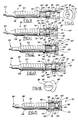
- FIG. 2 is an exploded side view of a needle valve and a cap in section of this invention;
- FIG. 3 is a front view of the cap;
- FIG. 4 is a sectional view of the cap assembled in a driving position on a head of the valve;
- FIG. 5 illustrates the cap assembled in a retainer position on the valve;
- FIG. 6 illustrates the cap secured in a limiter position on the valve;
- FIG. 7 is a perspective view of a carburetor assembly illustrating caps of this invention mounted on both the main and idle needle valves;
- FIG. 8 is a front view of a second carburetor configuration;
- FIG. 9 is a side sectional view of a second cap embodiment assembled in a retainer position on the valve;
- FIG. 10 is a front view of the second cap;
- FIG. 11 illustrates the second cap in a releasable driving position on the valve;
- FIG. 12 illustrates the second cap securely assembled in a limiter position on the valve;
- FIG. 13 is a side sectional view of a third cap embodiment assembled in a retainer position on a valve;
- FIG. 14 is a front view of the third cap;
- FIG. 15 illustrates the third cap securely assembled in a limiter position on the valve;
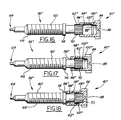
- FIG. 16 is a side sectional view of a fourth cap embodiment assembled in a driving position on the valve;
- FIG. 17 illustrates the fourth cap assembled in a retainer position on the valve; and
- FIG. 18 shows the fourth cap securely assembled in a limiter position on the valve.
- With reference to the drawings, FIGS. 1 & 1A illustrate a typical assembly of a hand-held
power tool 30 such as a hedge trimmer with a two-stroke gasoline engine 32 having acarburetor 34 with idle 36 and main 38 needle valves and limiter caps 40, 42 of this invention. The idle 36 and main 38 valves meter fuel flow during low speed and high speed engine operation respectively.
Thecarburetor 34 has anair inlet 44 attached to anair cleaner 46 and anoutlet 48 in communication with anintake manifold 50 of theengine 32. Theengine 32 andcarburetor 34 are enclosed by a housing orshroud 52 with agrommet 54 having a pair ofaccess openings 56 axially aligned with eachcap - As shown in FIGS. 1A and 2, each
valve cylindrical shank 60 with ahead 62 at one end and a generally conicalvalve control surface 64 at the other end. Theshank 60 has a plurality ofthreads 66 about its outer periphery to engage with complementary threads (not shown) within the carburetor body to enable secure insertion of thevalve 36 therein and axial adjustment of theneedle valve 36 within a fuel flow passage. - Typically, a recess or
slot 68 is provided in the free end of thevalve 36 for receiving an adjustment tool, such as the blade of a screwdriver, for facilitating rotational adjustment of thevalve 36. Alternatively, a plurality of axial ridges orknurls 70 in the outer peripheral surface of thehead 62 may be engaged by a tool or manually for adjustment. Unintentional valve rotation during engine vibration is prevented by aspring 72 received over thevalve shank 60 and disposed between thecarburetor body 34 and aflange 74 on thevalve shank 60 adjacent thehead 62. - Preferably, the
head 62 of eachneedle valve shoulder 76 at the end of the valve and asecond segment 78 adjacent thespring retaining flange 74 by a circumferentiallycontinuous groove 80. Preferably, for firm engagement with the cap, thehead segments cap body 82 with anarm 84 projecting therefrom for limiting valve rotation and hence adjustment. The location of thearm 84, 84' on the body is the only difference between these caps. For axially telescoping thecap 40 over the end of avalve 36, thebody 82 has apassage 86 therein. Portions within thepassage 86 enable thecap 40 to be carried on avalve 36 in a freely rotating first position during assembly andlimiter arm 84 orientation, in a second position securing thecap 40 to thevalve 36 to limit adjustment and maintain emissions calibration, and in a third position to releasably drivingly engage thevalve 36 to perform fuel flow adjustment. Thebody 82 also has a generally slottedrecess 88 in the face of the free end of thecap 40 for receiving an adjustment tool therein. - The
limiter arm 84 is an arcuate flanged projection which extends generally radially outwardly from thebody 82 for abutting against astop 90 carried by or operably associated with the carburetor to limit rotation to less than a complete revolution. The stop may be an adjacent valve shank, a cap mounted thereon (FIG. 7) 90, a fixed stop 90' projecting from the carburetor body (FIG. 8), a projection extending from thehousing 52,grommet 54, or engine 32 (not shown), or the like. Preferably, thearm 84 is set axially back from the cap face to allow adjustment without the surroundinggrommet 54 objectionably interfering with thearm 84. However, in applications where thecarburetor 34 is not enclosed by agrommet 54 orshroud 52, thearm 84 may be located anywhere along the axial length of thebody 82. Preferably, the angle subtended by theflange arm 84 is sufficient to limit the extent to which thevalve 36 can be rotated to fine tune the engine, or to conform with any required emissions regulation. Thearm 84 may have alocator indention 92 in its outer periphery to facilitate its use in an automatic cap feeding device. - As shown in FIG. 4, the
cap 40 may be mounted on thevalve 36 in a driving position with a first portion or circumferentiallycontinuous rib 94 within thepassage 86 adjacent the opening releasably drivingly engaging theknurled head 62. When releasably drivingly mounted in this position, thecap 40 and hence thevalve 36 can be rotated in unison to perform initial calibration adjustments. The mouth of thepassage 86 has achamfer 96 to facilitate entry of thevalve head 62 into therib 94. - Frequently, however, the
cap 40 is first placed on thehead 62 in the retainer position shown in FIG. 5 which allows thecap 40 to rotate freely with respect to thevalve 36 while retained thereon. When mounted in this position, thefirst segment 76 of thevalve head 62 is received in a circumferentiallycontinuous recess 98 in thepassage 86 with sufficient clearance to enable free rotation. Preferably, therib 94 of thepassage 86 and theshoulder 76 of thevalve 36 have an interference fit to retard removal from this freely rotating position. If desired, to releasably drivingly couple thecap 40 to theshank 60 of thevalve 36 for adjusting it, thecap 40 can be pushed slightly axially inwardly to engage thechamfer 96 with thesecond head segment 78 to adjust thevalve 36 by rotating thecap 40. When in this releasable driving position, thechamfer 102 and portion of thefirst rib 94adjacent chamfer 96 within thecap passage 86 may also releasably engage the knurled first 76 and second 78 head segments respectively. Upon releasing thecap 40, it will normally return to the retainer position where it can freely rotate relative to thevalve 36. - As shown in FIG. 6, to securely couple the
cap 40 to thevalve 36, thecap 40 may be pressed further axially onto thevalve 36 so thehead 62 frictionally engages and/or intermeshes with a circumferentially continuous rib in athird portion 100 of thepassage 86. To facilitate insertion of thehead 62 into thethird portion 100, it has aninclined camming surface 102. Preferably, therib 100 has an interference fit and when received in this position the material of the inner peripheral surfaces of the first 94 and third 100 portions deform around the knurls of thesecond head segment 78 to securely couple together thevalve 36 andcap 40 for simultaneous rotation and to resist removal of thecap 40. An interference fit between an adjacent shoulder of a circumferentiallycontinuous recess 104 at the end of thepassage 86 and the adjacent edge of thefirst segment 76 of thehead 62 securely locks thecap 40 to thevalve 36 further preventing removal. - FIGS. 9-12 illustrate a second form of a needle 36' and a cap 40'. The needle valve 36' is essentially the same as
needle 36 except that the first head segment 76' has aslot 68 therein for receiving the blade of a tool, such as a screwdriver, to rotate the valve 36' and aperipheral cam surface 106. To facilitate insertion of a tool through the cap 40' to engage theslot 68 of the needle valve 36', thebody 82 has anaccess hole 108 through the free end thereof. In all other respects, the cap 40' has essentially the same construction ascap 40. - As shown in FIG. 9, the cap 40' can be disposed in a first position on the needle valve 36' where it is retained thereon while being freely rotatable relative to the valve 36' so that it does not drivingly engage it. As illustrated in FIG. 11, the cap 36' can be pushed slightly axially inward of this position, either manually or with a tool engaging slot 88' or an
arcuate relief indentation 89 inflange 84, to releasably drivingly engage thechamfer surface 96 with the adjacent end of thesecond head segment 78 to drivingly turn the valve 36' by rotating the cap 40'. If necessary, a portion of thefirst rib 94 adjacent thechamfer 96 may also releasably engage thesecond head segment 78 to facilitate adjusting the valve 36'. When released, the cap 40' will normally return to the retained position (FIG. 9) where it can freely rotate relative to the valve 36'. Alternatively, the valve can be directly adjusted by inserting a tool throughbore 108 and engagingslot 68. As shown in FIG. 12, the cap 40' can be pressed further axially onto the valve 36' to a second position where the valve 36' and cap 40' are securely coupled together to limit rotation of the valve 36'. If desired, fine adjustment may be made by using a tool to engage slot 88' orindention 89 in the cap orslot 68 in the first segment 76' of the valve head 62'. - FIGS. 13-15 illustrate a third form of the invention with needle valve 36' and
cap 40. Since thecap 40 has a closed free end with a drivingslot 88 therein, once thecap 40 is received on the needle valve 36', theslot 68 in the head 62' of the valve 36' cannot be directly engaged to rotate the valve 36'. - As shown in FIG. 13, in a first position the
cap 40 is retained on the valve 36' while being freely rotatable relative to the valve 36' and can be pushed slightly axially inward of this position to engage the chamferedportion 96 with the head 62' to drivingly turn the valve 36' by rotating thecap 40. As shown in FIG. 15, thecap 40 can be pushed further axially onto the valve 36' to a second position to couple and secure thecap 40 and valve 36' for rotation therewith to limit adjustment of the valve 36'. - A fourth form of the invention is shown in FIGS. 16-18 with a needle valve 36'' and a
cap 40". As shown in FIG. 17, the cap 40'' is releasably retained and freely rotates in a first position on the valve 36'' by the cooperation of a circumferentially continuous recess 98'' in the passage of the cap 40'' and a head 62'' on the free end of thevalve 36". The cap 40'' is retained on the head 62'' in the freely rotating position by the cooperation of the adjacent edge or shoulder of the recess 98'' which has a slight interference fit with the adjacent edge of thehead 62". As shown in FIG. 18, in a second position, the cap 40'' is securely coupled to the valve 36'' by frictional or intermeshing engagement of the head 62'' with athird portion 100" of the passage to limit adjustment of thevalve 36". Insertion of the head 62'' into theinner rib 100" is facilitated by achamfer 102" at the entrance thereto. As shown in FIG. 16, if desired, initially the cap 40'' can be releasably drivingly engaged with the head 62'' of the needle valve 36'' by pushing the shoulder of the first passage portion 94'' into engagement with the leading portion of thehead 62". The chamfer 96'' facilitates engaging the shoulder with thehead 62". - In use, the caps may be pressed onto the
valve 36 to a position where thefirst segment 76 of thevalve head 62 engages with therib 94 of thecap passage 86. While in this position, thevalve 36 may be adjusted, such as during flow testing or final calibration. To adjust thevalve 36, torque is applied to thecap 40 through an adjustment tool engaging thecap recess 88.
Usually, however, thecap 40 is initially mounted to and carried by thevalve 36 in the freely rotating retainer position. Advantageously, thecap 40 may be attached in this retainer position any time after flow testing so that thecarburetor 34 may be shipped or other assembly operations performed without inadvertently disturbing the valve calibration. For example, it may be desirable to assemble thegrommet 54,shroud 52 or both after attaching thecap 40 in this retainer position. During this stage of assembly, fine adjustment of fuel flow to tune actual engine operation in compliance with emissions requirements may be simply and easily achieved. - To fine tune fuel flow while in the freely rotating retainer position, the slotted
cap face 88 is engaged by an adjustment tool and a sufficient axially inward force is applied against thecap 40 causing thefirst passage section 94 to releasably engage the knurledsecond segment 78 enabling rotation in unison. While engaged, thecap 40 andvalve 36 may be rotated until engine exhaust emissions fall within the desired range. If thelimiter arm 84 abuts against astop 90 and more adjustment is needed, the applied force can be withdrawn releasing thecap 40 from frictional engagement and thearm 84 freely rotated away from thestop 90 without rotating thevalve 36 to provide an additional range of adjustment. To further adjust thevalve 36, sufficient force may be once again applied to engage thehead 62 and a torque applied to rotate thecap 40 andvalve 36 in unison. In this manner, thecap 40 may be used to ratchet thevalve 36 in either direction to provide an unlimited range of adjustment. However, if the cap 40' has a through-opening 108, as in FIGS. 9-12, emissions calibration may also be performed at this assembly stage simply by directly engaging thevalve 36 with an adjustment tool. - Before securing the
cap 40 to thevalve 36, thecap 40 is freely rotated to easily and accurately orient thelimiter arm 84 relative to the calibratedvalve 36 and stopmember 90. To stay within emissions restrictions while allowing sufficient user adjustment to keep the engine efficiently operating, the limiter arm position, arm flange width and stop configuration and position are selected, designed and constructed as will be apparent to skilled persons and need not be described in further detail. - Once the
limiter arm 84 is circumferentially positioned on thevalve 36, a force is applied to axially move thecap 40 into firm frictional engagement with theknurled head 62 preventing removal and tampering. Optionally, valve adjustment may be performed after final cap assembly if the allowable range of rotation is sufficient to properly calibrate fuel flow. In this final position,valve 36 rotation in either direction is restricted by thearm 84 abutting with astop 90 preventing emissions-violating overadjustment by an end user while enabling a sufficient adjustment range to fine tune engine performance in response to a wide range of operating conditions. - Preferably, the limiter caps are of one piece, unitary construction for simpleness and ease of manufacture, and are constructed from a generally homogeneous material such as Zytel or Minlon, nylon formulations which are both registered trademarks of E. I. Du Pont De Nemours and Company, a different nylon formulation, Delrin (a POM thermoplastic) also a Du Pont material, or another high temperature thermoplastic material. A cap constructed of any of these materials is strong and resilient and able to deform around the knurls of the valve head to more positively frictionally secure the cap to the valve while resisting brittle fracture if tampered with. More generally, however, the caps could also be composed of a phenolic, polyurethane, polyacrylic, rubber or some other plastic material.
Claims (13)
- A cap (40; 42) for tamper-proof limiting of adjustment of fuel flow in a carburetor (34) by a valve (36; 38) having a rotatable shank (60) with a head (62) end projecting from the carburetor comprising: a body (82) having a passage (86) therein constructed and arranged to be telescopically received over the head end of the shank of the valve, a first retainer (94) in said passage to retain said body in a first telescoped position on the shank with the shank being freely rotatable relative to said body, an engagement element (102) in said passage to engage with the head end when said body is telescoped over the shank and in a second position axially spaced from said first position to releasably drivingly couple the shank with said body so that the shank and said body can rotate in unison to adjust the valve when said body is in said second position, an arm (84) fixed to said body and projecting generally radially thereof, and characterized by a second retainer (100) in said passage to engage with the head end when said body is telescoped over the shank in a third position spaced from said first and second positions to securely retain said body in said third position so that the shank and body can rotate only in unison and said arm limits the extent of rotation of the shank to less than one revolution when said body is in said third position by engagement of said arm (84) with at least one stop (90) operably associated therewith, whereby when said body is telescoped over the shank and in said first position the shank can rotate relative to said body, in said second position said body can releasably engage and drive or rotate the valve, and in said third position said body and the shank are securely engaged and can only be rotated in unison and with said arm engagable with at least one stop to permanently limit further rotation of the shank and cap to less than one complete revolution to thereby permit and permanently limit further adjustment of the valve.
- The cap of claim 1 characterized by said passage (86) extending completely through said body (82) and being constructed and arranged to permit an adjustment tool to be disposed therein and engaged with a slot (68) in the head (62) end of the shank (60) for rotating the shank relative to the carburetor (34) when the cap is telescopically received in said first position on the shank.
- The cap of claim 1 characterized by a recess (88) in an end of said body (82), having a non-circular cross-section and constructed and arranged to receive a tool therein for rotating the cap relative to the carburetor, and wherein when said body is in the second position axially displaced from said first and third positions, said body drivingly engages the shank (60) so that rotating said body also rotates the shank in unison therewith to adjust fuel flow of the carburetor.
- The cap of claim 1 characterized by a recess (88) in an end of said body (82), having a non-circular cross-section and constructed to receive a tool therein for rotating the cap relative to the carburetor, and the engagement element (102) engages with the shank (60) for drivingly rotating the shank in unison with rotation of said body when said body is in the second position thereon axially spaced from both said first and third positions, whereby when said body is in the second position rotation of said cap by a tool disposed in said recess of said body drivingly rotates the shank of the valve (36; 38) to adjust fuel flow of the carburetor.
- The cap of claim 1 characterized by said engagement element being a ramp (102) disposed in said passage (86) adjacent said second retainer (100) and constructed and arranged to facilitate engagement of the shank (60) with said second retainer when said body (82) is generally axially moved to said third position on the shank.
- The cap of claim 1 characterized by a locator notch (92) in the outer periphery of said arm (84) for facilitating the location and orientation of the cap for assembly relative to the shank (60).
- The cap of claim 1 characterized by said at least one stop (90) carried by the carburetor having a shank (60) of another fuel flow adjusting valve of the carburetor which projects into the arcuate path of rotation of said arm (84) of said body at least when said body (82) is in its third position.
- The cap of claim 1 characterized by said at least one stop (90) carried by the carburetor having a body of another limiter cap telescopingly received over a shank of another fuel flow adjusting valve of the carburetor which projects into the arcuate path of rotation of said arm (84) of said body at least when said body is in its third position (fig. 7).
- The cap of claim 1 characterized by said at least one stop (90) carried by the carburetor having a projection fixed to the body of the carburetor and disposed in the arcuate path of said arm (84) at least when said body is in said third position on the shank.
- The cap of claim 1 characterized by said body (82) and arm (84) being of one homogeneous piece of plastic material which is at least somewhat resilient.
- The cap of claim 1 characterized by said second retainer (100) having a press fit with the shank (60) when said body (82) is in said third position on the shank.
- The cap of claim 1 characterized by a recess (88) in an end of said body (82) having a non-circular cross-section and constructed to receive a tool therein for rotating the cap relative to the carburetor, and wherein when said body is telescoped over the shank (60) and in a second position axially spaced from said first and third positions, the engagement element (102) in said passage (86) engages the shank for rotating said body and the shank in unison therewith when in said second position to adjust fuel flow of the carburetor, and said second retainer includes-a latch in said passage and constructed and arranged to latch with the shank when said body is telescoped over the shank and in said third position to retard removal of the cap (40; 42) from the valve (36; 38).
- The cap of claim 1 characterized by a recess (88) in an end of said body (82), having a non-circular cross-section and constructed to receive a tool therein for rotating said cap relative to the carburetor when said body is telescoped over the shank (60) and in the second position axially displaced from said first and third positions.
Applications Claiming Priority (2)
| Application Number | Priority Date | Filing Date | Title |
|---|---|---|---|
| US07/949,895 US5236634A (en) | 1992-09-23 | 1992-09-23 | Carburetor needle valve adjustment limiter cap and method of adjusting fuel flow |
| US949895 | 1992-09-23 |
Publications (2)
| Publication Number | Publication Date |
|---|---|
| EP0589149A1 EP0589149A1 (en) | 1994-03-30 |
| EP0589149B1 true EP0589149B1 (en) | 1997-07-30 |
Family
ID=25489639
Family Applications (1)
| Application Number | Title | Priority Date | Filing Date |
|---|---|---|---|
| EP19930109852 Expired - Lifetime EP0589149B1 (en) | 1992-09-23 | 1993-06-18 | Carburettor needle valve adjustment limiter cap |
Country Status (4)
| Country | Link |
|---|---|
| US (2) | US5236634A (en) |
| EP (1) | EP0589149B1 (en) |
| JP (1) | JP2521404B2 (en) |
| DE (1) | DE69312611T2 (en) |
Families Citing this family (40)
| Publication number | Priority date | Publication date | Assignee | Title |
|---|---|---|---|---|
| JPH06317222A (en) * | 1993-04-30 | 1994-11-15 | Shinagawa Diecast Kogyo Kk | Fuel adjusting device of carburetor |
| JPH08210186A (en) * | 1994-12-01 | 1996-08-20 | Shinagawa Diecast Kogyo Kk | Air-fuel ratio adjusting device of carburetor |
| JPH0882245A (en) * | 1994-09-13 | 1996-03-26 | Shinagawa Diecast Kogyo Kk | Fuel control device for carburetor |
| US5772927A (en) * | 1994-12-01 | 1998-06-30 | U.S.A. Zama, Inc. | Carburetor fuel adjusting device |
| US5603869A (en) * | 1994-10-19 | 1997-02-18 | Wci Outdoor Products, Inc. | Fuel mixture limitation device |
| IES68052B2 (en) | 1995-02-17 | 1996-05-15 | Barcarole Ltd | An adjustment screw apparatus |
| JP2919305B2 (en) * | 1995-05-19 | 1999-07-12 | 株式会社日本ウォルブロー | Device for restricting operation of fuel regulating valve in carburetor |
| US5630965A (en) * | 1995-06-02 | 1997-05-20 | U.S.A. Zama, Inc. | Low force limit device |
| US5984281A (en) * | 1995-08-30 | 1999-11-16 | Walbro Corporation | Carburetor needle valve and limiter cap installation and adjustment apparatus |
| US5753148A (en) * | 1995-08-30 | 1998-05-19 | Walbro Corporation | Carburetor needle valve adjustment limiter cap apparatus and method of adjusting fuel flow |
| IES70513B2 (en) * | 1996-03-26 | 1996-11-27 | Barcarole Ltd | A carburetor adjustment screw apparatus |
| US5707561A (en) * | 1996-07-18 | 1998-01-13 | Walbro Corporation | Tamper resistant carburetor needle valve adjustment limiter |
| US6003845A (en) * | 1998-03-24 | 1999-12-21 | Walbro Corporation | Fuel mixture adjusting and limiting device |
| DE19833541C2 (en) | 1998-07-25 | 2000-07-13 | Stihl Maschf Andreas | Fuel adjusting screw on a carburetor for an internal combustion engine |
| JP2000297703A (en) | 1999-04-09 | 2000-10-24 | Nippon Walbro:Kk | Fuel jet supporting structure of carburetor |
| US6467757B1 (en) * | 1999-09-27 | 2002-10-22 | Walbro Japan, Inc. | Carburetor valve adjustment limiter cap assembly |
| US6402125B1 (en) * | 2000-03-29 | 2002-06-11 | Walbro Corporation | Carburetor valve rotational setting retainer assembly |
| US6302384B1 (en) | 2000-06-01 | 2001-10-16 | Walbro Corporation | Needle valve carburetor |
| DE10044025B4 (en) * | 2000-09-06 | 2012-04-05 | Andreas Stihl Ag & Co. | Carburetor for an internal combustion engine with at least one adjusting screw |
| US6454246B1 (en) | 2000-11-17 | 2002-09-24 | Walbro Corporation | Carburetor with separate nozzle post member |
| US6662822B2 (en) * | 2001-11-16 | 2003-12-16 | Apcom, Inc. | One-way nut fastener |
| US7007931B2 (en) * | 2002-06-03 | 2006-03-07 | Walbro Japan, Inc. | Rotary throttle valve carburetor |
| US20050040547A1 (en) * | 2002-07-11 | 2005-02-24 | Walbro Engine Management, L.L.C. | Carburetor air-fuel mixture adjustment assembly |
| US7070173B2 (en) * | 2002-07-11 | 2006-07-04 | Walbro Engine Management, L.L.C. | Carburetor air-fuel mixture adjustment assembly |
| US6691988B1 (en) * | 2002-09-18 | 2004-02-17 | Electrolux Home Products, Inc. | Tamper resistant carburetor mixture needles |
| JP2004132215A (en) * | 2002-10-09 | 2004-04-30 | Zama Japan Kk | Fuel adjusting device of carburetor |
| US6884976B2 (en) * | 2002-11-27 | 2005-04-26 | The Boeing Company | Induction heating for localized joining of structural members |
| US6814343B2 (en) * | 2002-12-10 | 2004-11-09 | Walbro Engine Management, L.L.C. | Carburetor with plastic idle speed adjustment screw |
| DE202004012860U1 (en) * | 2004-02-05 | 2005-06-16 | Dolmar Gmbh | Limiter cap for carburetor, has adjustment prevention device and guiding nose, where cap surrounds portion of set screw for positive locking, and transition area between screw head and needle extends in ring shape around needle |
| US7121533B2 (en) * | 2004-05-27 | 2006-10-17 | Husqvarna Outdoor Products Inc. | Air filter housing with tamper resistant carburetor feature |
| US7097165B1 (en) | 2005-04-13 | 2006-08-29 | Walbro Engine Management, L.L.C. | Carburetor fuel adjustment and limiter assembly |
| US7240896B1 (en) | 2005-05-05 | 2007-07-10 | Walbro Engine Management, L.L.C. | Carburetor fuel adjustment assembly |
| JP2009138652A (en) * | 2007-12-07 | 2009-06-25 | Walbro Japan Inc | Adjustment restriction device of fuel adjusting valve for carburetor |
| US8348244B2 (en) | 2010-07-24 | 2013-01-08 | Walbro Engine Management, L.L.C. | Carburetor valve adjustment limiter |
| JP5925481B2 (en) * | 2011-12-21 | 2016-05-25 | 株式会社ミクニ | Vaporizer pilot screw adjustment angle regulating device |
| US9777637B2 (en) | 2012-03-08 | 2017-10-03 | General Electric Company | Gas turbine fuel flow measurement using inert gas |
| CN108266288A (en) * | 2018-03-13 | 2018-07-10 | 重庆大江动力设备制造有限公司 | A kind of high altitude localities carburetor arrangement |
| US11118536B2 (en) | 2018-12-17 | 2021-09-14 | Walbro Llc | Tamper resistant adjustment valve for a charge forming device |
| JP7291614B2 (en) * | 2019-11-28 | 2023-06-15 | 株式会社やまびこ | limit cap |
| JP7851813B2 (en) * | 2022-07-20 | 2026-04-27 | 株式会社やまびこ | Flow rate adjustment limiting member |
Family Cites Families (11)
| Publication number | Priority date | Publication date | Assignee | Title |
|---|---|---|---|---|
| US3618906A (en) * | 1967-08-18 | 1971-11-09 | Ford Motor Co | Device and process for limiting idling fuel in carburetors |
| FR2291362A1 (en) * | 1974-11-15 | 1976-06-11 | Sibe | IMPROVEMENTS TO SCREW ADJUSTING DEVICES FOR CARBURETORS |
| JPS6039469Y2 (en) * | 1976-04-23 | 1985-11-26 | 日産自動車株式会社 | carburetor idle adjustment device |
| JPS5443322A (en) * | 1977-09-12 | 1979-04-05 | Tlv Co Ltd | Steam trap |
| JPS5516133U (en) * | 1978-07-17 | 1980-02-01 | ||
| JPS6221730Y2 (en) * | 1978-08-21 | 1987-06-02 | ||
| JPS55104556A (en) * | 1978-12-29 | 1980-08-11 | Mitsubishi Motors Corp | Carburetor |
| US4283353A (en) * | 1979-05-15 | 1981-08-11 | Colt Industries Operating Corp | Tamper proof sealing plug |
| US4242290A (en) * | 1979-07-30 | 1980-12-30 | Ford Motor Company | Carburetor idle mixture screw enclosure assembly |
| JPS6018132A (en) * | 1983-07-11 | 1985-01-30 | 鈴木 四郎 | Automatic chicken grilling spit |
| JPH0333462A (en) * | 1989-06-30 | 1991-02-13 | Shinagawa Diecast Kogyo Kk | Diaphragm carburettor |
-
1992
- 1992-09-23 US US07/949,895 patent/US5236634A/en not_active Expired - Fee Related
-
1993
- 1993-06-18 EP EP19930109852 patent/EP0589149B1/en not_active Expired - Lifetime
- 1993-06-18 DE DE69312611T patent/DE69312611T2/en not_active Expired - Fee Related
- 1993-06-30 JP JP16194593A patent/JP2521404B2/en not_active Expired - Fee Related
- 1993-08-13 US US08/106,410 patent/US5322645A/en not_active Expired - Lifetime
Also Published As
| Publication number | Publication date |
|---|---|
| DE69312611D1 (en) | 1997-09-04 |
| DE69312611T2 (en) | 1997-12-04 |
| JP2521404B2 (en) | 1996-08-07 |
| JPH06137214A (en) | 1994-05-17 |
| US5322645A (en) | 1994-06-21 |
| US5236634A (en) | 1993-08-17 |
| EP0589149A1 (en) | 1994-03-30 |
Similar Documents
| Publication | Publication Date | Title |
|---|---|---|
| US5236634A (en) | Carburetor needle valve adjustment limiter cap and method of adjusting fuel flow | |
| US5753148A (en) | Carburetor needle valve adjustment limiter cap apparatus and method of adjusting fuel flow | |
| US5984281A (en) | Carburetor needle valve and limiter cap installation and adjustment apparatus | |
| US5707561A (en) | Tamper resistant carburetor needle valve adjustment limiter | |
| US4271095A (en) | Idle adjusting device for a carburetor | |
| US5955007A (en) | Carburetor fuel adjusting device | |
| US5635113A (en) | Carburetor adjustment screw apparatus | |
| US8544829B2 (en) | Adjustment safeguard | |
| US5525267A (en) | Tamper resistant limit cap | |
| EP0589405B1 (en) | Carburettor needle valve adjustment limiter cap | |
| US11293380B2 (en) | Charge forming device with adjustable valve limiter | |
| US7097165B1 (en) | Carburetor fuel adjustment and limiter assembly | |
| US5630965A (en) | Low force limit device | |
| CA2430016C (en) | Tamper resistant carburetor mixture needles | |
| US6467757B1 (en) | Carburetor valve adjustment limiter cap assembly | |
| US11761403B2 (en) | Charge forming device with tamper resistant adjustable valve | |
| JPS632904Y2 (en) | ||
| JPH07286560A (en) | Operation limiting device for fuel adjusting needle valve of carburetor | |
| IE930887A1 (en) | An adjustment screw apparatus | |
| IE75665B1 (en) | An adjustment screw apparatus |
Legal Events
| Date | Code | Title | Description |
|---|---|---|---|
| PUAI | Public reference made under article 153(3) epc to a published international application that has entered the european phase |
Free format text: ORIGINAL CODE: 0009012 |
|
| AK | Designated contracting states |
Kind code of ref document: A1 Designated state(s): DE GB IT SE |
|
| 17P | Request for examination filed |
Effective date: 19940509 |
|
| 17Q | First examination report despatched |
Effective date: 19950303 |
|
| GRAG | Despatch of communication of intention to grant |
Free format text: ORIGINAL CODE: EPIDOS AGRA |
|
| GRAH | Despatch of communication of intention to grant a patent |
Free format text: ORIGINAL CODE: EPIDOS IGRA |
|
| GRAH | Despatch of communication of intention to grant a patent |
Free format text: ORIGINAL CODE: EPIDOS IGRA |
|
| GRAA | (expected) grant |
Free format text: ORIGINAL CODE: 0009210 |
|
| AK | Designated contracting states |
Kind code of ref document: B1 Designated state(s): DE GB IT SE |
|
| REF | Corresponds to: |
Ref document number: 69312611 Country of ref document: DE Date of ref document: 19970904 |
|
| PLBE | No opposition filed within time limit |
Free format text: ORIGINAL CODE: 0009261 |
|
| STAA | Information on the status of an ep patent application or granted ep patent |
Free format text: STATUS: NO OPPOSITION FILED WITHIN TIME LIMIT |
|
| 26N | No opposition filed | ||
| PGFP | Annual fee paid to national office [announced via postgrant information from national office to epo] |
Ref country code: GB Payment date: 19990602 Year of fee payment: 7 |
|
| PG25 | Lapsed in a contracting state [announced via postgrant information from national office to epo] |
Ref country code: GB Free format text: LAPSE BECAUSE OF NON-PAYMENT OF DUE FEES Effective date: 20000618 |
|
| GBPC | Gb: european patent ceased through non-payment of renewal fee |
Effective date: 20000618 |
|
| PGFP | Annual fee paid to national office [announced via postgrant information from national office to epo] |
Ref country code: SE Payment date: 20040621 Year of fee payment: 12 |
|
| PGFP | Annual fee paid to national office [announced via postgrant information from national office to epo] |
Ref country code: DE Payment date: 20040802 Year of fee payment: 12 |
|
| PG25 | Lapsed in a contracting state [announced via postgrant information from national office to epo] |
Ref country code: IT Free format text: LAPSE BECAUSE OF NON-PAYMENT OF DUE FEES;WARNING: LAPSES OF ITALIAN PATENTS WITH EFFECTIVE DATE BEFORE 2007 MAY HAVE OCCURRED AT ANY TIME BEFORE 2007. THE CORRECT EFFECTIVE DATE MAY BE DIFFERENT FROM THE ONE RECORDED. Effective date: 20050618 |
|
| PG25 | Lapsed in a contracting state [announced via postgrant information from national office to epo] |
Ref country code: SE Free format text: LAPSE BECAUSE OF NON-PAYMENT OF DUE FEES Effective date: 20050619 |
|
| PG25 | Lapsed in a contracting state [announced via postgrant information from national office to epo] |
Ref country code: DE Free format text: LAPSE BECAUSE OF NON-PAYMENT OF DUE FEES Effective date: 20060103 |
|
| EUG | Se: european patent has lapsed |