EP0589140A2 - Bit allocation method in subband coding - Google Patents
Bit allocation method in subband coding Download PDFInfo
- Publication number
- EP0589140A2 EP0589140A2 EP93106842A EP93106842A EP0589140A2 EP 0589140 A2 EP0589140 A2 EP 0589140A2 EP 93106842 A EP93106842 A EP 93106842A EP 93106842 A EP93106842 A EP 93106842A EP 0589140 A2 EP0589140 A2 EP 0589140A2
- Authority
- EP
- European Patent Office
- Prior art keywords
- bits
- allocated
- subband
- value obtained
- total number
- Prior art date
- Legal status (The legal status is an assumption and is not a legal conclusion. Google has not performed a legal analysis and makes no representation as to the accuracy of the status listed.)
- Granted
Links
- 238000000034 method Methods 0.000 title claims abstract description 26
- 238000013139 quantization Methods 0.000 claims abstract description 7
- 238000005070 sampling Methods 0.000 claims description 2
- 230000005236 sound signal Effects 0.000 description 8
- 230000003044 adaptive effect Effects 0.000 description 2
- 230000005540 biological transmission Effects 0.000 description 2
- 230000003247 decreasing effect Effects 0.000 description 2
- 238000010586 diagram Methods 0.000 description 2
- 239000011159 matrix material Substances 0.000 description 2
- 230000002708 enhancing effect Effects 0.000 description 1
- 230000004044 response Effects 0.000 description 1
- 238000003786 synthesis reaction Methods 0.000 description 1
- 230000002123 temporal effect Effects 0.000 description 1
- 230000001755 vocal effect Effects 0.000 description 1
Images

Classifications
-
- H—ELECTRICITY
- H03—ELECTRONIC CIRCUITRY
- H03M—CODING; DECODING; CODE CONVERSION IN GENERAL
- H03M7/00—Conversion of a code where information is represented by a given sequence or number of digits to a code where the same, similar or subset of information is represented by a different sequence or number of digits
- H03M7/30—Compression; Expansion; Suppression of unnecessary data, e.g. redundancy reduction
-
- G—PHYSICS
- G10—MUSICAL INSTRUMENTS; ACOUSTICS
- G10L—SPEECH ANALYSIS TECHNIQUES OR SPEECH SYNTHESIS; SPEECH RECOGNITION; SPEECH OR VOICE PROCESSING TECHNIQUES; SPEECH OR AUDIO CODING OR DECODING
- G10L19/00—Speech or audio signals analysis-synthesis techniques for redundancy reduction, e.g. in vocoders; Coding or decoding of speech or audio signals, using source filter models or psychoacoustic analysis
- G10L19/02—Speech or audio signals analysis-synthesis techniques for redundancy reduction, e.g. in vocoders; Coding or decoding of speech or audio signals, using source filter models or psychoacoustic analysis using spectral analysis, e.g. transform vocoders or subband vocoders
- G10L19/0204—Speech or audio signals analysis-synthesis techniques for redundancy reduction, e.g. in vocoders; Coding or decoding of speech or audio signals, using source filter models or psychoacoustic analysis using spectral analysis, e.g. transform vocoders or subband vocoders using subband decomposition
-
- G—PHYSICS
- G10—MUSICAL INSTRUMENTS; ACOUSTICS
- G10L—SPEECH ANALYSIS TECHNIQUES OR SPEECH SYNTHESIS; SPEECH RECOGNITION; SPEECH OR VOICE PROCESSING TECHNIQUES; SPEECH OR AUDIO CODING OR DECODING
- G10L19/00—Speech or audio signals analysis-synthesis techniques for redundancy reduction, e.g. in vocoders; Coding or decoding of speech or audio signals, using source filter models or psychoacoustic analysis
- G10L19/002—Dynamic bit allocation
-
- H—ELECTRICITY
- H04—ELECTRIC COMMUNICATION TECHNIQUE
- H04B—TRANSMISSION
- H04B1/00—Details of transmission systems, not covered by a single one of groups H04B3/00 - H04B13/00; Details of transmission systems not characterised by the medium used for transmission
- H04B1/66—Details of transmission systems, not covered by a single one of groups H04B3/00 - H04B13/00; Details of transmission systems not characterised by the medium used for transmission for reducing bandwidth of signals; for improving efficiency of transmission
- H04B1/667—Details of transmission systems, not covered by a single one of groups H04B3/00 - H04B13/00; Details of transmission systems not characterised by the medium used for transmission for reducing bandwidth of signals; for improving efficiency of transmission using a division in frequency subbands
Definitions
- the present invention relates to subband coding of an audio signal, and more particularly to a bit allocation method for enhancing coding efficiency by decreasing each value of an initial bit allocation with respect to corresponding blocks of subbands.
- the audio coding method includes a waveform coding method for coding the instantaneous amplitude of audio signals; an analysis-synthesis coding method wherein an audio generating apparatus is approximated to a model in compliance with an audio source and vocal path characteristic, and audio is displayed by a parameter of the approximation; and a high-efficiency transmission method by multiplexing wherein the existence of an audio signal on time axis is detected, and a silent section is compressed to realize the high-efficiency transmission.
- Subband coding is a kind of the waveform coding method, wherein an audio signal is split into a plurality of frequency bands, the signal of each band is down-sampled at the nyquist rate to thereby be converted into a low-band signal, and then adaptive pulse code modulation is performed.
- overall audio quality can be enhanced by allocating more quantization bits to a band in which aural energy is concentrated. Also, quantization noise affects only a split band without affecting other bands.
- the Comotti Consultatif International Télégraphique et Téléphonique specifies a subband coding and adaptive differential PCM (SBC-ADPCM) system which codes an audio signal of a 7KHz broad band into 64Kbits as a recommendation (see G722).
- SBC-ADPCM subband coding and adaptive differential PCM
- an audio signal is split into subbands having a plurality of successive frequency bands via an analysis filter.
- Each subband signal SB m is quantized block-by-block via a quantizer.
- the quantized subband signal QSB m consists of a plurality of successive signal blocks, and each signal block has a q-numbered samples. Respective samples in the signal block is quantized with an allocated number of bits ab[m].
- index m is an integer from 1 to M.
- the quantizer includes a bit-need determiner for determining a needed number of bits bf[m] for a certain signal block in the respectively corresponding signal blocks in the subband signal SB m .
- the needed number of bits bf[m] is related to the number of bits which represents the samples of each signal block.
- the quantizer includes a bit allocator for allocating an allocable number of bits TB in order to obtain allocated number of bits ab[m] in response to the needed number of bits of the corresponding signal blocks in the subband signals.
- the bit reallocator eliminates components which are below a threshold Wm in accordance with a noise-masking curve of the human auditory system.
- the quantized signal blocks are temporally divided and multiplexed, and then transmitted.
- needed number of bits bf[m] required for the quantization of each block signal is determined.
- needed number of bits bf[m] is determined by a signal power pwr_m and a threshold Wm in each signal block of a subband signal.
- Signal power pwr_m can be produced by the following equation: where S i represents the amplitude of the ith signal in a block having q-sample blocks in subband signal SB m . All signal powers pwr_m with respect to the corresponding blocks of subband signals from SB1 to SB M are determined in accordance with the foregoing equation.
- the signal powers can be given by a vector group ⁇ pwr ⁇ .
- a vector group ⁇ W ⁇ [D] ⁇ pwr ⁇ + ⁇ Wr ⁇
- [D] is a matrix of constants, whose coefficient d ij is multiplied by signal power pwr_j of the q-sample blocks of a subband signal SBj in order to calculate the threshold of a subband signal SBi induced by the q-sample blocks of subband signal SB j
- ⁇ Wr ⁇ represents the threshold of subband signal SB i .
- bf[m] K1 log2 (SFm2/3Wm) 1/2
- K1 is a constant having a value of 1
- SF m is the largest sample value among the q-sample blocks of subband signal SB m .
- allocated number of bits ab[m] allocated to each subband is determined according to needed number of bits bf[m].
- a subband jm which requires the largest number of bits among bf[m], that is, bf[1], bf[2],... bf[M] is selected. Then, it is determined whether allocated number of bits ab[jm] of the selected subband is zero.
- the sample values of the q-sample blocks in the subband signal have sign bits. Accordingly, at least two bits (the sign bit and an effective bit) are required for quantizing the sample values. Allocated number of bits ab[m] is provided to quantize the q-sample blocks of each subband in such a manner that b1-bit (e.g., two bits) is allocated for a first allocation, and b2-bit (e.g., one bit) is allocated for a second allocation.
- b1-bit e.g., two bits
- b2-bit e.g., one bit
- the initially allocated number of bits b1 is different from reallocated number of bits b2, which requires a separate algorithm and apparatus to thereby complicate the system.
- a bit allocation method in a subband coding method including the steps of dividing digital data with a sampling frequency into a plurality of subband signals having successive frequency bands, dividing each subband signal into a plurality of blocks having q samples, and allocating ab[m], that is, ab[1], ab[2],...., ab[M] to each block for quantizing each sample, said bit allocation method comprising: a first step of calculating a needed number of bits bf[m] required for quantization for each block having q samples of each subband signal; a second step of allocating one bit to every subband whose power is greater than a threshold; a third step of selecting a subband jm whose needed number of bits bf[m] is the largest, replacing a needed number of bits bf[jm] with a value obtained by subtracting one from the needed number of bits bf[jm], replacing an allocated number of bits ab[jm] with a value obtained by adding one to the
- an allocated number of bits ab[m] which represents the number of bits allocated to the block of each subband signal is cleared (step 112).
- An initially allocated number of bits b1 is allocated to allocated number of bits ab[m] of a block of a subband signal SB m whose signal power pwr_m is greater than a threshold Wm among respective blocks in the subbands.
- initially allocated number of bits b1 is an integer having a value, e.g., 2 (step 114).
- bf[jm] is a needed number of bits bf[m] of a subband which has the largest needed number of bits (step 120).
- step 122 it is determined whether the allocated number of bits ab[jm] of subband jm is greater than the maximum allocated number of bits a_max. If allocated number of bits ab[jm] is greater than maximum allocated number of bits a_max, the program branches to step 138 since more bits cannot be allocated to the searched block (step 122).
- allocated number of bits ab[jm] is smaller than maximum allocated number of bits a_max, it is checked whether allocated number of bits ab[jm] equals zero.
- allocated number of bits ab[jm] is not zero, the program branches to step 136 (step 130).
- allocated number of bits ab[jm] equals zero, it is checked whether available total number of bits TB is greater than or equal to initially allocated number of bits b1. If available total number of bits TB is smaller than initially allocated number of bits b1, the program branches to step 138 (step 132).
- step 134 If available total number of bits TB is greater than or equal to initially allocated number of bits b1, then, the following operations are executed: needed number of bits bf[jm] is replaced with a value obtained by subtracting initially allocated number of bits b1 from bf[jm]; allocated number of bits ab[jm] is replaced with initially allocated number of bits b1; available total number of bits TB is replaced with a value obtained by subtracting b1 from TB; and the program proceeds to step 140 (step 134).
- step 136 needed number of bits bf[jm] is replaced with a value obtained by subtracting b2 from bf[jm]; allocated number of bits ab[jm] is replaced with a value obtained by add b2 to ab[jm]; TB is replaced with a value obtained by subtracting b2 from available total number of bits TB; and the program proceeds to step 140 (step 136).
- step 138 needed number of bits bf[jm] is changed into - ⁇ , and then the program proceeds to step 140.
- bit reallocating program is finished (step 140).
- FIG. 2 is a flowchart for showing a bit allocation method according to the present invention.
- an allocated number of bits ab[m] which represents the number of bits allocated to the block of each subband signal is cleared (step 212).
- One is allocated to allocated number of bits ab[m] of a block of a subband whose signal power pwr_m is greater than a threshold Wm among respective blocks in the subbands (step 214).
- bf[jm] is a needed number of bits bf[m] of a subband which has the largest needed number of bits (step 220).
- step 222 it is determined whether the allocated number of bits ab[jm] of subband jm is greater than or equal to the maximum allocated number of bits a_max. If allocated number of bits ab[jm] is greater than or equal to maximum allocated number of bits a_max, the program branches to step 238 since no more bits can be allocated to the searched block (step 222).
- step 240 step 234. Thereafter, in step 238, needed number of bits bf[jm] is changed into - ⁇ , and then the program proceeds to step 240.
- bits bf[m] are checked whether they are - ⁇ or not.
- the bit reallocating program is finished (step 240).
- step 242 If there is a needed number of bits bf[m] which is not - ⁇ , it is checked whether or not available total number of bits TB is smaller than "one.” When TB is not smaller than "one,” the program returns to step 220 (step 242).
- FIG. 3 is a block diagram showing an apparatus for performing the bit allocation program according to the flowchart shown in FIG. 2.
- the bit allocation apparatus shown in FIG. 3 has a first memory 310 which stores available total number of bits TB. Available total number of bits TB is decrement-counted one-by-one via an operation path consisting of first memory 310, first subtractor 312 and a first switch S1. Also, number K of the subband whose allocated number of bits ab[m] is "one" in step 252 is increment-counted via first memory 310, a first adder 314 and first switch S1.
- a first comparator 342 detects the result whether or not available total number of bits TB stored in first memory is smaller than "one,” and the result is supplied to an OR operator 344.
- a second memory 320 stores allocated number of bits ab[m]. Allocated number of bits ab[m] is increment-counted one-by-one via an operation path consisting of second memory 320, a second adder 324 and a third switch S3. The replacement of allocated number of bits ab[m] with "zero" in step 252 of FIG. 2, is executed via an operation path consisting of a third memory 328, a second switch S2 and second memory 320.
- a third comparator 340 receives both allocated number of bits ab[jm] of subband SB jm whose needed number of bits occupies the largest number among the bf[m], and stored in second memory 320, and maximum allocated number of bits a_max stored in seventh memory 326, and checks whether the condition (i.e., ab[jm] ⁇ a_max) is satisfied. Then, the result is supplied to OR operator 344.
- a fifth memory 330 stores needed number of bits bf[m] of each subband. Needed number of bits bf[m] is decrement-counted one-by-one via an operational path consisting of fifth memory 330, a second subtractor 334 and a fourth switch S4. Fourth switch S4 is driven by means of an output signal of OR operator 344, and allows - ⁇ in a sixth memory 336 to be supplied to needed number of bits bf[jm] when allocated number of bits ab[jm] is more than or equal to maximum allocated number of bits a_max or available total number of bits TB is below "one.”
- a fourth comparator 332 detects index jm of the subband having the largest value among needed number of bits bf[m] stored in fifth memory 330, and supplies the detected value to second memory 320 and fifth memory 330.
- the bits allocated to the subband is consecutively increased one-by-one, so that the bit difference between subbands can be decreased.
- bit-utilization ratio can be increased.
- bit allocation is incremented by one, which simplifies the hardware.
Landscapes
- Engineering & Computer Science (AREA)
- Physics & Mathematics (AREA)
- Signal Processing (AREA)
- Health & Medical Sciences (AREA)
- Audiology, Speech & Language Pathology (AREA)
- Human Computer Interaction (AREA)
- Computational Linguistics (AREA)
- Acoustics & Sound (AREA)
- Multimedia (AREA)
- Computer Networks & Wireless Communication (AREA)
- Spectroscopy & Molecular Physics (AREA)
- Theoretical Computer Science (AREA)
- Compression, Expansion, Code Conversion, And Decoders (AREA)
- Transmission Systems Not Characterized By The Medium Used For Transmission (AREA)
Abstract
Description
- The present invention relates to subband coding of an audio signal, and more particularly to a bit allocation method for enhancing coding efficiency by decreasing each value of an initial bit allocation with respect to corresponding blocks of subbands.
- Various audio coding methods for processing audio signals have been suggested by utilizing statistical characteristics of a temporal or frequency region and the human auditory system. The audio coding method includes a waveform coding method for coding the instantaneous amplitude of audio signals; an analysis-synthesis coding method wherein an audio generating apparatus is approximated to a model in compliance with an audio source and vocal path characteristic, and audio is displayed by a parameter of the approximation; and a high-efficiency transmission method by multiplexing wherein the existence of an audio signal on time axis is detected, and a silent section is compressed to realize the high-efficiency transmission.
- Subband coding is a kind of the waveform coding method, wherein an audio signal is split into a plurality of frequency bands, the signal of each band is down-sampled at the nyquist rate to thereby be converted into a low-band signal, and then adaptive pulse code modulation is performed. In coding each band, overall audio quality can be enhanced by allocating more quantization bits to a band in which aural energy is concentrated. Also, quantization noise affects only a split band without affecting other bands. The Comité Consultatif International Télégraphique et Téléphonique (CCITT) specifies a subband coding and adaptive differential PCM (SBC-ADPCM) system which codes an audio signal of a 7KHz broad band into 64Kbits as a recommendation (see G722).
- Detailed description of such subband codings of audio signals are presented in papers entitled: "Journal of Audio Engineering Society," (Vol. 27, No. 11, pp. 855-865. November 1979); "The Bell System Technical Journal," (pp. 1633-1653, September 1981); and "IEEE Transactions on Acoustics, Speech and Signal Processing," (Vol. ASSP-30, No. 5, pp. 751-765, October 1982).
- In subband coding, an audio signal is split into subbands having a plurality of successive frequency bands via an analysis filter. Each subband signal SBm is quantized block-by-block via a quantizer. The quantized subband signal QSBm consists of a plurality of successive signal blocks, and each signal block has a q-numbered samples. Respective samples in the signal block is quantized with an allocated number of bits ab[m]. Here, index m is an integer from 1 to M. The quantizer includes a bit-need determiner for determining a needed number of bits bf[m] for a certain signal block in the respectively corresponding signal blocks in the subband signal SBm. The needed number of bits bf[m] is related to the number of bits which represents the samples of each signal block. In addition to this, the quantizer includes a bit allocator for allocating an allocable number of bits TB in order to obtain allocated number of bits ab[m] in response to the needed number of bits of the corresponding signal blocks in the subband signals. The bit reallocator eliminates components which are below a threshold Wm in accordance with a noise-masking curve of the human auditory system. The quantized signal blocks are temporally divided and multiplexed, and then transmitted.
- The procedure for allocating the quantization bits to each subband will be described in detail with reference to European Patent No. 457,390 A1.
- First, a needed number of bits bf[m] required for the quantization of each block signal is determined. At this time, needed number of bits bf[m] is determined by a signal power pwr_m and a threshold Wm in each signal block of a subband signal.
- Signal power pwr_m can be produced by the following equation:

where Si represents the amplitude of the ith signal in a block having q-sample blocks in subband signal SBm. All signal powers pwr_m with respect to the corresponding blocks of subband signals from SB₁ to SBM are determined in accordance with the foregoing equation. - When all signal powers of the subband signals are produced, the signal powers can be given by a vector group {pwr}. By multiplying vector group {pwr} by an M × M matrix [D], and further adding a vector group {Wr}, a vector group {W} can be obtained as below:

where [D] is a matrix of constants, whose coefficient dij is multiplied by signal power pwr_j of the q-sample blocks of a subband signal SBj in order to calculate the threshold of a subband signal SBi induced by the q-sample blocks of subband signal SBj, and {Wr} represents the threshold of subband signal SBi. - The needed number of bits bf[m] is obtained by the following equation:

where, K₁ is a constant having a value of 1, and SFm is the largest sample value among the q-sample blocks of subband signal SBm. - Thereafter, available total number of bits TB allocable to entire subbands is allocated to each subband. At this time, allocated number of bits ab[m] allocated to each subband is determined according to needed number of bits bf[m]. First, a subband jm which requires the largest number of bits among bf[m], that is, bf[1], bf[2],... bf[M] is selected. Then, it is determined whether allocated number of bits ab[jm] of the selected subband is zero. If the allocated number of bits ab[jm] equals zero, the following equations are executed:


where TB denotes available total number of bits allocable to every subband. - If ab[jm] is not zero, the operation is executed as follows:


where b₁ and b₂ are integers and b₁ > b₂. - The allocation of the needed number of bits to each subband according to the above-described methods is repeated until no bit is left in available total number of bits TB, but only when the number of bits allocable to a certain subband is limited within a maximum number of bits a_max.
- The sample values of the q-sample blocks in the subband signal have sign bits. Accordingly, at least two bits (the sign bit and an effective bit) are required for quantizing the sample values. Allocated number of bits ab[m] is provided to quantize the q-sample blocks of each subband in such a manner that b₁-bit (e.g., two bits) is allocated for a first allocation, and b₂-bit (e.g., one bit) is allocated for a second allocation. Here, initially allocated number of bits b₁ is greater than reallocated number of bits b₂.
- In the conventional bit allocation, the initially allocated number of bits b₁ is different from reallocated number of bits b₂, which requires a separate algorithm and apparatus to thereby complicate the system.
- It is the object of the present invention to provide a simplified bit allocation method of subband coding.
- To achieve the object of the present invention, there is provided a bit allocation method in a subband coding method including the steps of dividing digital data with a sampling frequency into a plurality of subband signals having successive frequency bands, dividing each subband signal into a plurality of blocks having q samples, and allocating ab[m], that is, ab[1], ab[2],...., ab[M] to each block for quantizing each sample, said bit allocation method comprising:
a first step of calculating a needed number of bits bf[m] required for quantization for each block having q samples of each subband signal;
a second step of allocating one bit to every subband whose power is greater than a threshold;
a third step of selecting a subband jm whose needed number of bits bf[m] is the largest, replacing a needed number of bits bf[jm] with a value obtained by subtracting one from the needed number of bits bf[jm], replacing an allocated number of bits ab[jm] with a value obtained by adding one to the allocated number of bits ab[jm], and replacing the available total number of bits TB with a value obtained by subtracting one from the total number of bits TB allocable to entire blocks;
a fourth step of returning to the third step when the available total number of bits TB is more than one or equal to by checking the available total number of bits TB; and
a fifth step of replacing the allocated number of bits ab[m] with a value obtained by subtracting one from the allocated number of bits ab[m], replacing the available total number of bits TB with a value obtained by adding the number of subbands K whose allocated number of bits ab[m] is one to the available total number of bits TB, and returning to the third step, when the presence of a subband whose allocated number of bits ab[m] equals one is checked under the state that the available total number of bits TB is below one. - The above objects and other advantages of the present invention will become more apparent by describing in detail a preferred embodiment thereof with reference to the attached drawings in which:
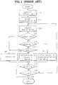
- FIG. 1 is a flowchart showing a conventional bit allocation method;
- FIG. 2 is a flowchart showing a bit allocation method according to the present invention; and
- FIG. 3 is a block diagram showing an apparatus for performing the bit allocation program according to the flowchart shown in FIG. 2.
- Before performing a conventional bit allocation method according to a flowchart shown in FIG. 1, a needed number of bits bf[m] required for quantizing a block having q-numbered samples in each subband signal is determined. Here, "q" is assumed as one, for convenience.
- First, an allocated number of bits ab[m] which represents the number of bits allocated to the block of each subband signal is cleared (step 112).
- An initially allocated number of bits b₁ is allocated to allocated number of bits ab[m] of a block of a subband signal SBm whose signal power pwr_m is greater than a threshold Wm among respective blocks in the subbands. Here, initially allocated number of bits b₁ is an integer having a value, e.g., 2 (step 114).
- A needed number of bits having the largest value among the corresponding blocks of respective subbands is searched, and its index jm is obtained. Here, bf[jm] is a needed number of bits bf[m] of a subband which has the largest needed number of bits (step 120).
- Then it is determined whether the allocated number of bits ab[jm] of subband jm is greater than the maximum allocated number of bits a_max. If allocated number of bits ab[jm] is greater than maximum allocated number of bits a_max, the program branches to step 138 since more bits cannot be allocated to the searched block (step 122).
- If allocated number of bits ab[jm] is smaller than maximum allocated number of bits a_max, it is checked whether allocated number of bits ab[jm] equals zero. When allocated number of bits ab[jm] is not zero, the program branches to step 136 (step 130). Meanwhile, when allocated number of bits ab[jm] equals zero, it is checked whether available total number of bits TB is greater than or equal to initially allocated number of bits b₁. If available total number of bits TB is smaller than initially allocated number of bits b₁, the program branches to step 138 (step 132).
- If available total number of bits TB is greater than or equal to initially allocated number of bits b₁, then, the following operations are executed: needed number of bits bf[jm] is replaced with a value obtained by subtracting initially allocated number of bits b₁ from bf[jm]; allocated number of bits ab[jm] is replaced with initially allocated number of bits b₁; available total number of bits TB is replaced with a value obtained by subtracting b₁ from TB; and the program proceeds to step 140 (step 134). Thereafter, needed number of bits bf[jm] is replaced with a value obtained by subtracting b₂ from bf[jm]; allocated number of bits ab[jm] is replaced with a value obtained by add b₂ to ab[jm]; TB is replaced with a value obtained by subtracting b₂ from available total number of bits TB; and the program proceeds to step 140 (step 136).
- In
step 138, needed number of bits bf[jm] is changed into - ∞, and then the program proceeds to step 140. - All needed number of bits bf[m] are checked whether they are - ∞ or not. When all needed number of bits bf[m] are - ∞, the bit reallocating program is finished (step 140).
- If there is a needed number of bits bf[m] which is not - ∞, it is checked whether or not available total number of bits TB is larger than or equal to reallocated number of bits b₂. When available total number of bits TB is larger than or equal to reallocated number of bits b₂, the program returns to step 120. If Tb is smaller than b₂, the bit reallocating program is finished (step 142).
- In the conventional bit allocation method shown in FIG. 1, it is checked whether allocated number of bits ab[jm] is zero, to determine the initial allocation. Then, according to the determination, when allocated number of bits ab[jm] is zero, i.e., for the initial allocation, initially allocated number of bits b₁ is allocated in
step 134. Conversely, reallocated number of bits b₂ is allocated in accordance withstep 136. This is because each sample of a block having q-numbered samples in a subblock has a sign bit, so that at least two bits are required for quantizing the respective samples with signs. The minimum allocated number of bits is satisfied by setting initially allocated number of bits b₁ to two. - However, in hardware performing the bit allocation in accordance with the flowchart shown in FIG. 1, separate blocks are required for performing the initial allocation and reallocation, which complicates the hardware.
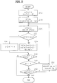
- FIG. 2 is a flowchart for showing a bit allocation method according to the present invention.
- First, an allocated number of bits ab[m] which represents the number of bits allocated to the block of each subband signal is cleared (step 212).
- "One" is allocated to allocated number of bits ab[m] of a block of a subband whose signal power pwr_m is greater than a threshold Wm among respective blocks in the subbands (step 214).
- A needed number of bits having the largest value among the blocks of respective subbands is searched, and its index jm is obtained. Here, bf[jm] is a needed number of bits bf[m] of a subband which has the largest needed number of bits (step 220).
- Then, it is determined whether the allocated number of bits ab[jm] of subband jm is greater than or equal to the maximum allocated number of bits a_max. If allocated number of bits ab[jm] is greater than or equal to maximum allocated number of bits a_max, the program branches to step 238 since no more bits can be allocated to the searched block (step 222).
- If allocated number of bits ab[jm] is smaller than maximum allocated number bits a_max, then, the following operations are executed: needed number of bits bf[jm] is replaced with a value obtained by subtracting "one" from bf[jm]; allocated number of bits ab[jm] is replaced with a value obtained by adding "one" to allocated number of bits ab[jm]; available total number of bits TB is replaced with a value obtained by subtracting "one" from TB; and the program proceeds to step 240 (step 234). Thereafter, in
step 238, needed number of bits bf[jm] is changed into - ∞, and then the program proceeds to step 240. - All needed number of bits bf[m] are checked whether they are - ∞ or not. When all needed number of bits bf[m] are - ∞, the bit reallocating program is finished (step 240).
- If there is a needed number of bits bf[m] which is not - ∞, it is checked whether or not available total number of bits TB is smaller than "one." When TB is not smaller than "one," the program returns to step 220 (step 242).
- When available total number of bits TB is smaller than "one," the existence of a subband whose allocated number of bits ab[m] equals "one." If there is no subband whose allocated number of bits ab[m] equals "one," the bit reallocating program is finished (step 250).
- When a subband whose allocated number of bits ab[m] equals "one" exists, available total number of bits TB is replaced with a value obtained by adding to TB the number K of the subband whose allocated number of bits ab[m] is "one," allocated number of bits ab[m] is replaced with "zero" and then the program returns to step 220 (step 252).
- FIG. 3 is a block diagram showing an apparatus for performing the bit allocation program according to the flowchart shown in FIG. 2. The bit allocation apparatus shown in FIG. 3 has a
first memory 310 which stores available total number of bits TB. Available total number of bits TB is decrement-counted one-by-one via an operation path consisting offirst memory 310,first subtractor 312 and a first switch S1. Also, number K of the subband whose allocated number of bits ab[m] is "one" instep 252 is increment-counted viafirst memory 310, afirst adder 314 and first switch S1. Afirst comparator 342 detects the result whether or not available total number of bits TB stored in first memory is smaller than "one," and the result is supplied to an ORoperator 344. - A
second memory 320 stores allocated number of bits ab[m]. Allocated number of bits ab[m] is increment-counted one-by-one via an operation path consisting ofsecond memory 320, asecond adder 324 and a third switch S3. The replacement of allocated number of bits ab[m] with "zero" instep 252 of FIG. 2, is executed via an operation path consisting of athird memory 328, a second switch S2 andsecond memory 320. - A
second comparator 346 receives available total number of bits TB fromfirst memory 310 and allocated number of bits ab[m] fromsecond memory 320 to thereby detect number K of the subband which satisfies the condition (i.e., TB < 1 and ab[m] = 1), so that the detected result is supplied to afourth memory 316. - A
third comparator 340 receives both allocated number of bits ab[jm] of subband SBjm whose needed number of bits occupies the largest number among the bf[m], and stored insecond memory 320, and maximum allocated number of bits a_max stored inseventh memory 326, and checks whether the condition (i.e., ab[jm] ≧ a_max) is satisfied. Then, the result is supplied to ORoperator 344. - A
fifth memory 330 stores needed number of bits bf[m] of each subband. Needed number of bits bf[m] is decrement-counted one-by-one via an operational path consisting offifth memory 330, asecond subtractor 334 and a fourth switch S4. Fourth switch S4 is driven by means of an output signal of ORoperator 344, and allows - ∞ in asixth memory 336 to be supplied to needed number of bits bf[jm] when allocated number of bits ab[jm] is more than or equal to maximum allocated number of bits a_max or available total number of bits TB is below "one." - A
fourth comparator 332 detects index jm of the subband having the largest value among needed number of bits bf[m] stored infifth memory 330, and supplies the detected value tosecond memory 320 andfifth memory 330. - In the bit allocation method according to the present invention, the bits allocated to the subband is consecutively increased one-by-one, so that the bit difference between subbands can be decreased.
- Moreover, after finishing the bit allocation, a subband whose allocated number of bits is "one" is searched to thus collect them, which are then reallocated to other subbands, so that the bit-utilization ratio can be increased.
- Furthermore, the bit allocation is incremented by one, which simplifies the hardware.
- While the present invention has been particularly shown and described with reference to particular embodiments thereof, it will be understood by those skilled in the art that various changes in form and details may be effected therein without departing from the spirit and scope of the invention as defined by the appended claims.
Claims (3)
- A bit allocation method in a subband coding method including the steps of dividing digital data with a sampling frequency into a plurality of subband signals having successive frequency bands, dividing each subband signal into a plurality of blocks having q samples, and allocating ab[m], that is, ab[1], ab[2],..., ab[M] number of bits to each block for quantizing each sample, said bit allocation method comprising:
a first step of calculating a needed number of bits bf[m] required for quantization for each block having q samples of each subband signal;
a second step of selecting a subband SBjm whose needed number of bits bf[m] is the largest among the result of first step, replacing the needed number of bits bf[jm] with a value obtained by subtracting one from said needed number of bits bf[jm], replacing an allocated number of bits ab[jm] with a value obtained by adding one to said allocated number of bits ab[jm], and replacing the available total number of bits TB with a value obtained by subtracting one from the total number of bits TB allocable to entire blocks;
a third step of returning to said second step when said available total number of bits TB is more than or equal to one by checking said available total number of bits TB; and
a fourth step of replacing said allocated number of bits ab[m] with a value obtained by subtracting one from said allocated number of bits ab[m], replacing said available total number of bits TB with a value obtained by replacing said available total number of bits (TB) with a value obtained by adding the number of subbands (K) whose allocated number of bits (ab[m]) is one to said available total number of bits, and returning to said second step, when the presence of a subband whose allocated number of bits equals one is checked under the state that said available total number of bits (TB) is below one. - A bit allocation method as claimed in claim 1, wherein, after said first step, further comprises the step of allocating one bit to every subband whose power is greater than a threshold.
- A bit allocation method as claimed in claim 1, wherein, before said step of replacing said allocated number of bits (ab[jm]) with a value obtained by subtracting one from said allocated number of bits (ab[jm]) in said second step, further comprises the step of ending bit allocation when all said allocated number of bits (ab[m]) are more than or equal to a maximum allocated number of bits (a_max) by comparing said allocated number of bits (ab[jm]) with each maximum allocated number of bits (a_max) of each subband.
Applications Claiming Priority (2)
| Application Number | Priority Date | Filing Date | Title |
|---|---|---|---|
| KR1718892 | 1992-09-21 | ||
| KR1019920017188A KR100188912B1 (en) | 1992-09-21 | 1992-09-21 | Bit reassigning method of subband coding |
Publications (3)
| Publication Number | Publication Date |
|---|---|
| EP0589140A2 true EP0589140A2 (en) | 1994-03-30 |
| EP0589140A3 EP0589140A3 (en) | 1994-05-25 |
| EP0589140B1 EP0589140B1 (en) | 1999-08-04 |
Family
ID=19339869
Family Applications (1)
| Application Number | Title | Priority Date | Filing Date |
|---|---|---|---|
| EP93106842A Expired - Lifetime EP0589140B1 (en) | 1992-09-21 | 1993-04-27 | Bit allocation method in subband coding |
Country Status (5)
| Country | Link |
|---|---|
| US (1) | US5479561A (en) |
| EP (1) | EP0589140B1 (en) |
| JP (1) | JP3121708B2 (en) |
| KR (1) | KR100188912B1 (en) |
| DE (1) | DE69325865T2 (en) |
Cited By (1)
| Publication number | Priority date | Publication date | Assignee | Title |
|---|---|---|---|---|
| EP0968497A1 (en) * | 1996-10-07 | 2000-01-05 | PictureTel Corporation | Variable length audio coding using a plurality of subband bit allocation patterns |
Families Citing this family (7)
| Publication number | Priority date | Publication date | Assignee | Title |
|---|---|---|---|---|
| US5664057A (en) * | 1993-07-07 | 1997-09-02 | Picturetel Corporation | Fixed bit rate speech encoder/decoder |
| KR100378790B1 (en) * | 1996-04-23 | 2003-05-01 | 엘지전자 주식회사 | Sub-band quantization level decoder |
| US8831933B2 (en) | 2010-07-30 | 2014-09-09 | Qualcomm Incorporated | Systems, methods, apparatus, and computer-readable media for multi-stage shape vector quantization |
| US9208792B2 (en) | 2010-08-17 | 2015-12-08 | Qualcomm Incorporated | Systems, methods, apparatus, and computer-readable media for noise injection |
| CN108198564B (en) * | 2013-07-01 | 2021-02-26 | 华为技术有限公司 | Signal encoding and decoding method and apparatus |
| US20150025894A1 (en) * | 2013-07-16 | 2015-01-22 | Electronics And Telecommunications Research Institute | Method for encoding and decoding of multi channel audio signal, encoder and decoder |
| CN105096957B (en) | 2014-04-29 | 2016-09-14 | 华为技术有限公司 | Process the method and apparatus of signal |
Citations (1)
| Publication number | Priority date | Publication date | Assignee | Title |
|---|---|---|---|---|
| EP0457390A1 (en) * | 1990-05-14 | 1991-11-21 | Koninklijke Philips Electronics N.V. | Encoding system comprising a subband coder, and a transmitter comprising an encoding system |
Family Cites Families (5)
| Publication number | Priority date | Publication date | Assignee | Title |
|---|---|---|---|---|
| US4516258A (en) * | 1982-06-30 | 1985-05-07 | At&T Bell Laboratories | Bit allocation generator for adaptive transform coder |
| NL8700985A (en) * | 1987-04-27 | 1988-11-16 | Philips Nv | SYSTEM FOR SUB-BAND CODING OF A DIGITAL AUDIO SIGNAL. |
| JPH03181232A (en) * | 1989-12-11 | 1991-08-07 | Toshiba Corp | Variable rate encoding system |
| US5367608A (en) * | 1990-05-14 | 1994-11-22 | U.S. Philips Corporation | Transmitter, encoding system and method employing use of a bit allocation unit for subband coding a digital signal |
| US5365553A (en) * | 1990-11-30 | 1994-11-15 | U.S. Philips Corporation | Transmitter, encoding system and method employing use of a bit need determiner for subband coding a digital signal |
-
1992
- 1992-09-21 KR KR1019920017188A patent/KR100188912B1/en not_active IP Right Cessation
-
1993
- 1993-04-27 DE DE69325865T patent/DE69325865T2/en not_active Expired - Fee Related
- 1993-04-27 EP EP93106842A patent/EP0589140B1/en not_active Expired - Lifetime
- 1993-04-30 JP JP05104738A patent/JP3121708B2/en not_active Expired - Fee Related
- 1993-04-30 US US08/054,211 patent/US5479561A/en not_active Expired - Lifetime
Patent Citations (1)
| Publication number | Priority date | Publication date | Assignee | Title |
|---|---|---|---|---|
| EP0457390A1 (en) * | 1990-05-14 | 1991-11-21 | Koninklijke Philips Electronics N.V. | Encoding system comprising a subband coder, and a transmitter comprising an encoding system |
Non-Patent Citations (1)
| Title |
|---|
| PHILIPS JOURNAL OF RESEARCH vol. 44, no. 2/3 , July 1989 , EINDHOVEN NL pages 329 - 343 VELDHUIS ET AL 'SUBBAND CODING OF DIGITAL AUDIO SIGNALS' * |
Cited By (2)
| Publication number | Priority date | Publication date | Assignee | Title |
|---|---|---|---|---|
| EP0968497A1 (en) * | 1996-10-07 | 2000-01-05 | PictureTel Corporation | Variable length audio coding using a plurality of subband bit allocation patterns |
| EP0968497A4 (en) * | 1996-10-07 | 2000-02-23 | Picturetel Corp | Variable length audio coding using a plurality of subband bit allocation patterns |
Also Published As
| Publication number | Publication date |
|---|---|
| KR940008279A (en) | 1994-04-29 |
| EP0589140B1 (en) | 1999-08-04 |
| US5479561A (en) | 1995-12-26 |
| JPH06216861A (en) | 1994-08-05 |
| DE69325865T2 (en) | 1999-11-25 |
| DE69325865D1 (en) | 1999-09-09 |
| KR100188912B1 (en) | 1999-06-01 |
| EP0589140A3 (en) | 1994-05-25 |
| JP3121708B2 (en) | 2001-01-09 |
Similar Documents
| Publication | Publication Date | Title |
|---|---|---|
| EP0279451B1 (en) | Speech coding transmission equipment | |
| US6308150B1 (en) | Dynamic bit allocation apparatus and method for audio coding | |
| JP3134455B2 (en) | High efficiency coding apparatus and method | |
| JP2906646B2 (en) | Voice band division coding device | |
| US5613035A (en) | Apparatus for adaptively encoding input digital audio signals from a plurality of channels | |
| KR100209870B1 (en) | Perceptual coding of audio signals | |
| US5732391A (en) | Method and apparatus of reducing processing steps in an audio compression system using psychoacoustic parameters | |
| EP1396841B1 (en) | Encoding apparatus and method, decoding apparatus and method, and program | |
| KR100397690B1 (en) | Data encoding device and method | |
| KR100273071B1 (en) | Method for coding signals and modulating analog signal | |
| JP3186292B2 (en) | High efficiency coding method and apparatus | |
| EP0702368A2 (en) | Method of recording and reproducing digital audio signal and apparatus thereof | |
| EP0345608A2 (en) | Data compression system and method with buffer control | |
| EP0720316A1 (en) | Adaptive digital audio encoding apparatus and a bit allocation method thereof | |
| ATE188305T1 (en) | APPARATUS, METHOD AND SYSTEM FOR COMPRESSING A DIGITAL INPUT SIGNAL IN MORE THAN ONE COMPRESSION MODE | |
| CN100405460C (en) | Coding an audio signal | |
| US7650278B2 (en) | Digital signal encoding method and apparatus using plural lookup tables | |
| EP0703677B1 (en) | Perceptual subband encoder | |
| US5491773A (en) | Encoding system comprising a subband coder for subband coding of a wideband digital signal constituted by first and second signal components | |
| KR0185998B1 (en) | Encoding system comprising a subband coder and a transmitter comprising an encoding system | |
| EP0721257A1 (en) | Bit allocation for multichannel audio coder based on perceptual entropy | |
| US5864802A (en) | Digital audio encoding method utilizing look-up table and device thereof | |
| US6466912B1 (en) | Perceptual coding of audio signals employing envelope uncertainty | |
| US6141637A (en) | Speech signal encoding and decoding system, speech encoding apparatus, speech decoding apparatus, speech encoding and decoding method, and storage medium storing a program for carrying out the method | |
| EP0589140B1 (en) | Bit allocation method in subband coding |
Legal Events
| Date | Code | Title | Description |
|---|---|---|---|
| PUAI | Public reference made under article 153(3) epc to a published international application that has entered the european phase |
Free format text: ORIGINAL CODE: 0009012 |
|
| AK | Designated contracting states |
Kind code of ref document: A2 Designated state(s): DE FR GB |
|
| PUAL | Search report despatched |
Free format text: ORIGINAL CODE: 0009013 |
|
| AK | Designated contracting states |
Kind code of ref document: A3 Designated state(s): DE FR GB |
|
| 17P | Request for examination filed |
Effective date: 19941109 |
|
| 17Q | First examination report despatched |
Effective date: 19971219 |
|
| GRAG | Despatch of communication of intention to grant |
Free format text: ORIGINAL CODE: EPIDOS AGRA |
|
| GRAG | Despatch of communication of intention to grant |
Free format text: ORIGINAL CODE: EPIDOS AGRA |
|
| GRAH | Despatch of communication of intention to grant a patent |
Free format text: ORIGINAL CODE: EPIDOS IGRA |
|
| GRAH | Despatch of communication of intention to grant a patent |
Free format text: ORIGINAL CODE: EPIDOS IGRA |
|
| GRAA | (expected) grant |
Free format text: ORIGINAL CODE: 0009210 |
|
| AK | Designated contracting states |
Kind code of ref document: B1 Designated state(s): DE FR GB |
|
| REF | Corresponds to: |
Ref document number: 69325865 Country of ref document: DE Date of ref document: 19990909 |
|
| ET | Fr: translation filed | ||
| PLBE | No opposition filed within time limit |
Free format text: ORIGINAL CODE: 0009261 |
|
| STAA | Information on the status of an ep patent application or granted ep patent |
Free format text: STATUS: NO OPPOSITION FILED WITHIN TIME LIMIT |
|
| 26N | No opposition filed | ||
| REG | Reference to a national code |
Ref country code: GB Ref legal event code: IF02 |
|
| PG25 | Lapsed in a contracting state [announced via postgrant information from national office to epo] |
Ref country code: FR Free format text: LAPSE BECAUSE OF NON-PAYMENT OF DUE FEES Effective date: 20070430 |
|
| PGFP | Annual fee paid to national office [announced via postgrant information from national office to epo] |
Ref country code: DE Payment date: 20080502 Year of fee payment: 16 |
|
| PGFP | Annual fee paid to national office [announced via postgrant information from national office to epo] |
Ref country code: GB Payment date: 20080430 Year of fee payment: 16 |
|
| GBPC | Gb: european patent ceased through non-payment of renewal fee |
Effective date: 20090427 |
|
| PG25 | Lapsed in a contracting state [announced via postgrant information from national office to epo] |
Ref country code: DE Free format text: LAPSE BECAUSE OF NON-PAYMENT OF DUE FEES Effective date: 20091103 |
|
| PG25 | Lapsed in a contracting state [announced via postgrant information from national office to epo] |
Ref country code: GB Free format text: LAPSE BECAUSE OF NON-PAYMENT OF DUE FEES Effective date: 20090427 |
|
| REG | Reference to a national code |
Ref country code: FR Ref legal event code: RN Effective date: 20121114 |
|
| REG | Reference to a national code |
Ref country code: FR Ref legal event code: D3 Effective date: 20130123 |
|
| PGFP | Annual fee paid to national office [announced via postgrant information from national office to epo] |
Ref country code: FR Payment date: 20121201 Year of fee payment: 16 |
|
| REG | Reference to a national code |
Ref country code: FR Ref legal event code: ST Effective date: 20130204 |
|
| PGRI | Patent reinstated in contracting state [announced from national office to epo] |
Ref country code: FR Effective date: 20130123 |
|
| PG25 | Lapsed in a contracting state [announced via postgrant information from national office to epo] |
Ref country code: FR Free format text: LAPSE BECAUSE OF NON-PAYMENT OF DUE FEES Effective date: 20090430 |
|
| PGRI | Patent reinstated in contracting state [announced from national office to epo] |
Ref country code: FR Effective date: 20130123 |