EP0588566A2 - Gerät und Verfahren zur Erzeugung einer gerasterten Reproduktion eines Bildes - Google Patents
Gerät und Verfahren zur Erzeugung einer gerasterten Reproduktion eines Bildes Download PDFInfo
- Publication number
- EP0588566A2 EP0588566A2 EP93307150A EP93307150A EP0588566A2 EP 0588566 A2 EP0588566 A2 EP 0588566A2 EP 93307150 A EP93307150 A EP 93307150A EP 93307150 A EP93307150 A EP 93307150A EP 0588566 A2 EP0588566 A2 EP 0588566A2
- Authority
- EP
- European Patent Office
- Prior art keywords
- dot
- original
- dots
- reference screen
- density values
- Prior art date
- Legal status (The legal status is an assumption and is not a legal conclusion. Google has not performed a legal analysis and makes no representation as to the accuracy of the status listed.)
- Granted
Links
Images


Classifications
-
- H—ELECTRICITY
- H04—ELECTRIC COMMUNICATION TECHNIQUE
- H04N—PICTORIAL COMMUNICATION, e.g. TELEVISION
- H04N1/00—Scanning, transmission or reproduction of documents or the like, e.g. facsimile transmission; Details thereof
- H04N1/40—Picture signal circuits
- H04N1/405—Halftoning, i.e. converting the picture signal of a continuous-tone original into a corresponding signal showing only two levels
- H04N1/4055—Halftoning, i.e. converting the picture signal of a continuous-tone original into a corresponding signal showing only two levels producing a clustered dots or a size modulated halftone pattern
Definitions
- the present invention relates to screened image reproduction and more particularly to a method and apparatus for electronically generating a screened reproduction of an image.
- U.S. Patent4,635,131 describes a method of and apparatus for producing halftone dot film of graduated density distribution.
- f(x) + g(y) f(x) + g(y) representative of the specific pattern corresponding to the density value.
- U.S. Patent 4,825,298 to Ikuta and Murai describes a technique for generating a screened reproduction of an image in which the density distribution of a given screen dot is expressed in three dimensions, wherein the area of the screen dot is expressed along X and Y axes and the density is expressed along a Z axis perpendicularthereto.
- Afilm coordinate generator generates film coordinates (u,v), corresponding to the position of an exposure beam on a recording film which position is detected by encoders. The film coordinates are in turn supplied to a screen coordinate generator to be converted into virtual screen coordinates (x,y).
- a beam control signal generator receives the coordinates (x,y) and an image signal corresponding to the position of the exposure beam to output a beam control signal indicating lighting of the exposure beam when one of the coordinates (x,y) is between upper and lower limit values, corresponding to the same, which are previously determined for each combination of the other of the coordinates (x,y) and the density value of the image signal.
- U.S. Patent 4,556,918 describes a method and apparatus for generating screened halftone images which includes means for assuming an area of halftone dots with desired periodicity and tone reproducibility, subdividing the area into minute cells and setting address values for each of the minute cells, computing out a threshold value of density for each of the cells as a function of the relevant address values and using the computed value as a threshold value of density for the cell, apparatus for obtaining a density- related video signal of the portion of the original corresponding to each of the cells by scanning the original, and apparatus for producing halftone dot signals by comparing the video signals and the threshold value of density with each other.
- Applicant/assignee's earlier U.S. Patent 5,079,721 describes apparatus and a technique for generating a screened reproduction of an image including the steps of providing a representation of an original having input density values representing the grey levels of various locations of the original for given color separation, defining a desired screen dot arrangement for the image, writing screen dots in a line by line fashion, wherein each screen dot is made up of a plurality of lines whose length and location determines the dot configuration and whose length and location is determined by an analog operation employing the input density values of the original and the desired screen dot arrangement.
- the present invention seeks to provide an improved technique and apparatus for generating a screened reproduction of an image.
- each of the plurality of spatial functions is stored in a vector memory.
- the step of employing includes the step of selection of one of the plurality of spatial functions for each combination of spatial variables.
- the step of selection includes the step of selecting a function having a maximum value.
- the step of selection includes the step of selecting a function having a minimum value.
- the employing step produces a two-dimensional result.
- the employing step includes a plurality of parallel selection steps.
- the plurality of parallel selection steps comprises a pair of selection steps.
- the employing step includes an arithmetic step operating on the results of the parallel selection steps.
- the employing step also includes the step of modifying the reference screen dots in accordance with a stored correction table.
- the employing step comprises the steps of:
- the step of selecting between the first result and the second result is carried out on the basis of the input density values of the original.
- the employing step also includes the step of employing at least one additional plurality of spatial functions to produce at least one additional result and wherein the step of selecting between the first result and the second result is operative to select between the first, second and at least one additional plurality of results.
- apparatus for generating a screened reproduction of an image comprising:
- apparatus for generating a screened reproduction of an image comprising:
- apparatus for generating a screened reproduction of an image comprising:
- each of the plurality of spatial functions is stored in a vector memory.
- the reference screen dot composer comprises a selector for selecting one of the plurality of spatial functions for each combination of spatial variables.
- the selector is operative for selecting a function having a maximum value.
- the selector is operative for selecting a function having a minimum value.
- the reference screen dot composer produces a two-dimensional result.
- the reference screen dot composer a plurality of parallel selectors.
- the plurality of parallel selectors comprises a pair of selectors.
- the reference screen dot composer is operative to carry out an arithmetic function on the results produced by the parallel selectors.
- the reference screen dot composer also includes apparatus for modifying the reference screen dots in accordance with a stored correction table.
- the reference screen dot composer comprises:
- the selector for selecting between the first result and the second result is operative using the input density values of the original.
- the reference screen dot composer also includes apparatus for employing at least one additional plurality of spatial functions to produce at least one additional result and wherein selector for selecting between the first result and the second result is operative to select between the first, second and at least one additional plurality of results.
- composition of reference screen dots is carried out by generating a grid- independent, reference screen dot value continuum.
- Fig. 1 illustrates a system for generating a screened reproduction of an image constructed and operative in accordance with a preferred embodiment of the present invention.
- the system preferably comprises a color separation scanner 10, such as a Scitex Smart Scanner, manufactured and sold by Scitex Corporation Ltd. of Herzlia, Israel, which is adapted to provide a digital color separation output of a color original.
- a color separation scanner 10 such as a Scitex Smart Scanner, manufactured and sold by Scitex Corporation Ltd. of Herzlia, Israel, which is adapted to provide a digital color separation output of a color original.
- the digital output of scanner 10 is normally stored on a image data disc 12 or any other suitable storage medium, which is accessible by a CPU 14, such as an Intel 80486.
- a CPU 14 such as an Intel 80486.
- Interfacing with the CPU 14 is an interactive workstation 16, such as a Scitex Prisma, manufactured and sold by Scitex Corporation Ltd. of Herzlia, Israel.
- CPU 14 interfaces with screen dot generation circuitry 18, which in turn provides a control output to laser beam control circuitry 24 in a laser plotter 26, such as a Raystar, manufactured and sold by Scitex Corporation Ltd. of Herzlia, Israel.
- Laser plotter 26 produces halftone film color separations 28 which are employed in a conventional process color printing press 30, to produce process color prints.
- Fig. 2 illustrates a typical halftone color separation which is stored on disc 12.
- Fig. 3 illustrates in enlarged detail, a small area 32 indicated on Fig. 2. It is noted that the gray level over area 32 varies thereacross.
- the halftone color separation in general and the small area 32 in particular are hereinafter termed the input image and are divided into a first multiplicity of pixels 34 which are arranged along coordinate axes l x and ly Pixels 34 typically have a resolution of 100 - 400 pixels per inch along each of the coordinate axes of the input image.
- Each average gray level for a pixel 34 is represented digitally by an input density level. There are typically provided 256 different input density levels, 0 being the lightest and 255 being the blackest.
- Fig. 4 illustrates the input density values for the pixels 34 of Fig. 3.
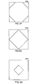
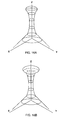
- FIG. 5A shows the round printing dot in a Cartesian frame of reference wherein the x and y axes represent spatial dimensions and the z axis represents the screen value. It is appreciated that truncation of the dot of Fig. 5A at a given z value produces a round dot whose dimensions are determined by the z value in accordance with the spatial functions which are employed to create the dot.
- Figs. 5F and 5G illustrate truncations of the dot of Fig. 5A, representing the printing dot at input densities of 75% and 50% respectively.
- FIG. 6A shows the square printing dot in a Cartesian frame of reference wherein the x and y axes represent spatial dimensions and the z axis represents the screen value. It is appreciated that truncation of the dot of Fig. 6Aat a given z value produces a square dot whose dimensions are determined by the z value in accordance with the spatial functions which are employed to create the dot.
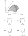
- Fig. 7A shows the combination printing dot in a Cartesian frame of reference wherein the x and y axes represent spatial dimensions and the z axis represents the screen value. It is appreciated that truncation of the dot of Fig. 7Aata a given z value produces a combination dot whose dimensions are determined by the z value in accordance with the spatial functions which are employed to create the dot.
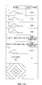
- Figs. 7B - 7E The various one-dimensional spatial functions which are employed to create the dot of Fig. 7A appear in Figs. 7B - 7E. In accordance with a preferred embodiment of the present invention, these spatial functions are combined in the following manner to achieve the dot of Fig. 7A:
- Figs. 7F - 7H illustrate truncations of the dot of Fig. 7A, representing the printing dot at input densities of 75%, 50% and 25% respectively.
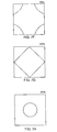
- Figs. 8A - 8E illustrate a gravure printing dot constructed and operative in accordance with a preferred embodiment of the present invention together with spatial functions employed to create the gravure printing dot.
- the gravure printing dot has characteristics of a square pyramid-shaped dot.
- Fig. 8A shows the gravure printing dot in a Cartesian frame of reference wherein the x and y axes represent spatial dimensions and the z axis represents the screen value. It is appreciated that truncation of the dot of Fig. 8A at a given z value produces a gravure dot whose dimensions are determined by the z value in accordance with the spatial functions which are employed to create the dot.
- Figs. 8B - 8E The various one-dimensional spatial functions which are employed to create the dot of Fig. 8A appear in Figs. 8B - 8E. In accordance with a preferred embodiment of the present invention, these spatial functions are combined in the following manner to achieve the dot of Fig. 8A:
- Figs. 8F - 8H illustrate truncations of the dot of Fig. 8A, representing the printing dot at input densities of 75%, 50% and 25% respectively.
- Figs. 9A - 9E illustrate a modified gravure printing dot constructed and operative in accordance with a preferred embodiment of the present invention together with spatial functions employed to create the modified gravure printing dot.
- the modified gravure printing dot has characteristics of a partially rounded square pyramid- shaped dot.
- Fig. 9A shows the modified gravure printing dot in a Cartesian frame of reference wherein the x and y axes represent spatial dimensions and the z axis represents the screen value. It is appreciated that truncation of the dot of Fig. 9A at a given z value produces a modified gravure dot whose dimensions are determined by the z value in accordance with the spatial functions which are employed to create the dot.
- X1A and Y1A are identical upside down parabola functions.
- the other two spatial functions X2A and Y2A are identical parabolas. This need not necessarily be the case.
- An asymmetrical dot may be realized by employing similar but non-identical spatial functions.
- Figs. 9F - 9H illustrate truncations of the dot of Fig. 9A, representing the printing dot at input densities of 75%, 50% and 25% respectively.
- Fig. 10 is a simplified block diagram of the dot generator employed in the apparatus of Fig. 1.
- the dot generator comprises a stored vector array 40 which includes vector information received from the CPU 14 prior to actual dot generation.
- the vector information includes the spatial functions mentioned hereinabove.
- a cell address is determined by a cell address generator 42, typically employing a set of registers and an arithmetic logic unit (ALU).
- ALU arithmetic logic unit
- a screen generator 44 calculates the screen value by operating on the spatial functions in stored vector array 40 by non-arithmetic operators.
- the screen generator 44 also carries out other mathematical functions in order to generate the screen values.
- the screen generator 44 may receive input density information of the original in order to enable automatic dot type selection to be made by the screen generator 44 in response to given levels of input densities of the original.
- the screen value output of screen generator 44 is preferably supplied to a bank 46 of look up tables which is operative to provide desired linearization and corrections to the screen value output.
- the output of the bank of look up tables 46 is supplied via a screen buffer 48 to a comparator 50.
- Comparator 50 also receives input density information of the original via an image buffer 52 and compares the input densities with the screen values thereof, effectively carrying out the truncation illustrated and described hereinabove.
- the output of comparator 50 is effectively an expose/do not expose instruction to the expose control circuitry 24 of laser plotter 26 (Fig. 1).
- Fig. 11 is a simplified block diagram of the vector array 40, the cell address generator 42 and the screen generator 44 shown in Fig. 10.
- Stored data vectors 60: X1A, Y1A, X2Aand Y2Aetc. receive x and y address parameters from respective x and y address generators 62 and 64 which form part of cell address generator42 (Fig. 10).
- the outputs from predetermined pairs of stored vectors 60 are supplied to non-arithmetic operators 66, each pair of which preferably output to an ALU 68.
- the output of each ALU 68 is supplied via a calibration look up table (CLUT) 70.
- a multiplexer 72 receives the outputs of all of the CLUTs 70 as well as CPU control and input density inputs which are used as selection criteria.
- Fig. 12 is a functional analog of one preferred embodiment of the apparatus shown in the block diagram illustration of Fig. 11. It is seen that in this preferred embodiment, the non-arithmetic operators 66 are effectively mini- mum/maximum selectors and the ALU 68 functions to sum the outputs of a pair of selectors 66.
- the CLUT 70 performs dot value calibration and the multiplexer 72 selects between the outputs of a plurality of different CLUTS 70.
- each CLUT 70 output represents a different dot type.
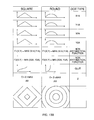
- Figs. 13A, 13B and 13C illustrate the construction of five types of dots.
- dot i.e. Gravure, Combination, Square, Round and Star
- four typical one dimensional spatial functions are illustrated, followed by the non- arithmetical functions which operate thereon.
- the output of CLUT 70 is illustrated, followed by the algorithm employed by the multiplexer 72.
- the dot configuration is then illustrated in the form of superimposed dot outlines for a plurality of different input densities of the original.
- Figs. 14A- 14F illustrate the operation of the apparatus of Figs. 11 and 12 for input densities of 25%, 40%, 50%, 51%, 60% and 75%.
- screen dot is either the star dot or the square dot, both of which appear in Fig. 13.
- Multiplexer 72 outputs the star dot for original input densities more than 50% and outputs the square dot for original input densities up to and including 50%.
- Figs. 15A - 15F illustrate the operation of the apparatus of Figs. 11 and 12 for input densities of 25%, 35%, 50%, 51%, 60% and 75%.
- screen dot is either the star dot or the combination dot, both of which appear in Fig. 13.
- Multiplexer 72 outputs the star dot for original input densities more than 50% and outputs the combination dot for original input densities up to and including 50%.
- Figs. 16A and 16B illustrate diagrams of the dot configuration versus input density for dots whose coverage of a given dot region need not increase monotonically with increasing input density. It may be appreciated that in certain cases a dot region may be exposed for a first input density and not be exposed for a higher input density. Such an occurrence may be envisioned by comparing Figs. 14C and 14D as well as Figs. 15C and 15D.
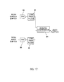
- Fig. 17 shows one particular preferred structure of comparator 50 of Fig. 10.
- the output of screen buffer 48 (Fig. 10) is supplied via a digital to analog converter 80 and a low pass filter 82 to an analog comparator 84.
- Analog comparator 84 also receives the output from image buffer 52 (Fig. 10) via a digital to analog converter 86 and an optional low pass filter 88.
- low pass filter 82 is adapted to extrapolate and interpolate the values stored in screen buffer 48 so as to provide an accurate reproduction of the dot density threshold.
- the inclusion of low pass filter 88 depends on the quality of the input image.
- comparator 84 is employed to control the operation of expose control circuitry 24 (Fig. 1), indicating when the laser plotter 26 (Fig. 1) is to write. It is noted that there may also be provided various additional control functions, such as intensity control, to enhance the operation of the laser plotter 26.
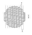
- Fig. 18 illustrates the construction of an output screen dot.
- the laser plotter 26 (Fig. 1) defines a plurality of parallel lines 92, having a spacing 94, and whose beginning and end are determined by the output of comparator 84.
- the screen dot is a composite of such lines. In a case wherein the input density values represented by the dot are uniform, the dot will have a generally symmetrical shape, as illustrated.
- each written line has infinite resolution along its length, because the on/off control inputs to the laser plotter are arrived at by comparison of two generally continuous analog signals.
Landscapes
- Engineering & Computer Science (AREA)
- Multimedia (AREA)
- Signal Processing (AREA)
- Facsimile Image Signal Circuits (AREA)
- Processing And Handling Of Plastics And Other Materials For Molding In General (AREA)
- Ultra Sonic Daignosis Equipment (AREA)
- Image Processing (AREA)
Applications Claiming Priority (2)
| Application Number | Priority Date | Filing Date | Title |
|---|---|---|---|
| US947282 | 1992-09-16 | ||
| US07/947,282 US5526143A (en) | 1992-09-16 | 1992-09-16 | Apparatus and technique for generating a screened reproduction of an image |
Publications (3)
| Publication Number | Publication Date |
|---|---|
| EP0588566A2 true EP0588566A2 (de) | 1994-03-23 |
| EP0588566A3 EP0588566A3 (en) | 1994-05-11 |
| EP0588566B1 EP0588566B1 (de) | 1998-05-27 |
Family
ID=25485888
Family Applications (1)
| Application Number | Title | Priority Date | Filing Date |
|---|---|---|---|
| EP93307150A Expired - Lifetime EP0588566B1 (de) | 1992-09-16 | 1993-09-10 | Gerät und Verfahren zur Erzeugung einer gerasterten Reproduktion eines Bildes |
Country Status (6)
| Country | Link |
|---|---|
| US (1) | US5526143A (de) |
| EP (1) | EP0588566B1 (de) |
| JP (1) | JPH0795404A (de) |
| AT (1) | ATE166759T1 (de) |
| DE (1) | DE69318784T2 (de) |
| IL (1) | IL107024A (de) |
Cited By (1)
| Publication number | Priority date | Publication date | Assignee | Title |
|---|---|---|---|---|
| WO2003019929A1 (en) * | 2001-08-27 | 2003-03-06 | Phototype Engraving Company | System for halftone screen production |
Families Citing this family (3)
| Publication number | Priority date | Publication date | Assignee | Title |
|---|---|---|---|---|
| EP0765748A3 (de) * | 1995-09-29 | 1997-08-13 | Goss Graphics Systems Inc | Einrichtung zum Ausrichten von Bildern in einem Kontrollsystem für eine Druckmaschine |
| US6266079B1 (en) | 1998-06-01 | 2001-07-24 | Aprion Digital Ltd. | Half-tone dot generation |
| US6382099B1 (en) | 1999-05-17 | 2002-05-07 | Mark L. Herrmann | Printing apparatus and method for preventing barring or banding on a printed substrate |
Citations (5)
| Publication number | Priority date | Publication date | Assignee | Title |
|---|---|---|---|---|
| DE2500564A1 (de) * | 1974-01-07 | 1975-07-10 | Crosfield Electronics Ltd | Verfahren und vorrichtung fuer eine gerastete bildreproduktion |
| US4635131A (en) * | 1984-10-11 | 1987-01-06 | D. S. Scanner Co., Ltd. | Method of and apparatus for producing halftone dot film of gradated density distribution |
| EP0207246A1 (de) * | 1985-06-12 | 1987-01-07 | Dainippon Screen Mfg. Co., Ltd. | Verfahren und Gerät zur Aufzeichnung eines Halbtonbildes |
| EP0292732A2 (de) * | 1987-05-26 | 1988-11-30 | Dainippon Screen Mfg. Co., Ltd. | Halbtonpunkterzeugungsvorrichtung und -Verfahren |
| EP0481602A2 (de) * | 1990-09-14 | 1992-04-22 | Minnesota Mining And Manufacturing Company | Eine allgemeine Kernfunktion zur elektronischen Erzeugung gerosterter Halbtöne |
Family Cites Families (23)
| Publication number | Priority date | Publication date | Assignee | Title |
|---|---|---|---|---|
| US3664248A (en) * | 1968-05-03 | 1972-05-23 | Technical Operations Inc | Optical processing of information including synthesis by complex amplitude addition of diffraction spectra |
| US3583804A (en) * | 1968-09-30 | 1971-06-08 | Technical Operations Inc | Photostorage and retrieval of multiple images by diffraction processes with cross-talk suppression |
| US3719127A (en) * | 1971-04-01 | 1973-03-06 | Technical Operations Inc | Spectral zonal information storage and retrieval |
| US4491964A (en) * | 1979-04-23 | 1985-01-01 | Recognition Equipment Incorporated | Image processing integrated circuit |
| US4456924A (en) * | 1980-04-14 | 1984-06-26 | Scitex Corporation Ltd. | Screened image reproduction |
| US4462024A (en) * | 1981-03-24 | 1984-07-24 | Rca Corporation | Memory scanning address generator |
| US4499489A (en) * | 1981-06-08 | 1985-02-12 | Dr. Ing. Rudolf Hell Gmbh | Production of screen printing blocks |
| JPS59122080A (ja) * | 1982-12-27 | 1984-07-14 | Leo Giken:Kk | 網点画像の発生方法 |
| JPS60213170A (ja) * | 1984-04-06 | 1985-10-25 | Dainippon Screen Mfg Co Ltd | 画像走査記録装置における網点パタ−ン発生方法 |
| US4621286A (en) * | 1984-05-29 | 1986-11-04 | Rca Corporation | Spatial-temporal frequency interleaved processing of a television signal with reduced amplitude interleaved sections |
| US4676611A (en) * | 1984-11-14 | 1987-06-30 | New York University | Method and apparatus for visual-evoked responses |
| US4694342A (en) * | 1986-05-01 | 1987-09-15 | Eastman Kodak Company | Spatial filter useful for removing noise from video images and for preserving detail therein |
| US4991109A (en) * | 1986-08-28 | 1991-02-05 | Hughes Aircraft Company | Image processing system employing pseudo-focal plane array |
| US4991111A (en) * | 1986-08-28 | 1991-02-05 | Hughes Aircraft Company | Real-time image processing system |
| US4762998A (en) * | 1987-05-12 | 1988-08-09 | Eastman Kodak Company | Method for reading out an image signal stored in a transparent photostimulable phosphor |
| US4774574A (en) * | 1987-06-02 | 1988-09-27 | Eastman Kodak Company | Adaptive block transform image coding method and apparatus |
| US4984097A (en) * | 1989-01-31 | 1991-01-08 | Nynex Corporation | Halftone reproduction with enhanced gray level reproducibility |
| CA2020627C (en) * | 1989-07-07 | 1995-06-27 | Yuzo Koike | Image processing apparatus |
| US4970593A (en) * | 1989-08-28 | 1990-11-13 | Sperry Marine Inc. | Video image enhancement utilizing a two-dimensional digital aperture correction filter |
| US5079721A (en) * | 1990-05-18 | 1992-01-07 | Scitex Corporation Ltd. | Apparatus for generating a screened reproduction of an image |
| US5249238A (en) * | 1991-03-19 | 1993-09-28 | Komerath Narayanan M | Spatial cross-correlating velocimeter |
| US5212741A (en) * | 1992-01-21 | 1993-05-18 | Eastman Kodak Company | Preprocessing of dot-matrix/ink-jet printed text for Optical Character Recognition |
| US5377041A (en) * | 1993-10-27 | 1994-12-27 | Eastman Kodak Company | Method and apparatus employing mean preserving spatial modulation for transforming a digital color image signal |
-
1992
- 1992-09-16 US US07/947,282 patent/US5526143A/en not_active Expired - Fee Related
-
1993
- 1993-09-10 DE DE69318784T patent/DE69318784T2/de not_active Expired - Fee Related
- 1993-09-10 EP EP93307150A patent/EP0588566B1/de not_active Expired - Lifetime
- 1993-09-10 AT AT93307150T patent/ATE166759T1/de not_active IP Right Cessation
- 1993-09-15 IL IL10702493A patent/IL107024A/xx not_active IP Right Cessation
- 1993-09-16 JP JP5230537A patent/JPH0795404A/ja active Pending
Patent Citations (5)
| Publication number | Priority date | Publication date | Assignee | Title |
|---|---|---|---|---|
| DE2500564A1 (de) * | 1974-01-07 | 1975-07-10 | Crosfield Electronics Ltd | Verfahren und vorrichtung fuer eine gerastete bildreproduktion |
| US4635131A (en) * | 1984-10-11 | 1987-01-06 | D. S. Scanner Co., Ltd. | Method of and apparatus for producing halftone dot film of gradated density distribution |
| EP0207246A1 (de) * | 1985-06-12 | 1987-01-07 | Dainippon Screen Mfg. Co., Ltd. | Verfahren und Gerät zur Aufzeichnung eines Halbtonbildes |
| EP0292732A2 (de) * | 1987-05-26 | 1988-11-30 | Dainippon Screen Mfg. Co., Ltd. | Halbtonpunkterzeugungsvorrichtung und -Verfahren |
| EP0481602A2 (de) * | 1990-09-14 | 1992-04-22 | Minnesota Mining And Manufacturing Company | Eine allgemeine Kernfunktion zur elektronischen Erzeugung gerosterter Halbtöne |
Cited By (2)
| Publication number | Priority date | Publication date | Assignee | Title |
|---|---|---|---|---|
| WO2003019929A1 (en) * | 2001-08-27 | 2003-03-06 | Phototype Engraving Company | System for halftone screen production |
| US7492480B2 (en) | 2001-08-27 | 2009-02-17 | Phototype Engraving Company | System for halftone screen production |
Also Published As
| Publication number | Publication date |
|---|---|
| IL107024A0 (en) | 1993-12-28 |
| DE69318784T2 (de) | 1998-09-24 |
| DE69318784D1 (de) | 1998-07-02 |
| JPH0795404A (ja) | 1995-04-07 |
| US5526143A (en) | 1996-06-11 |
| ATE166759T1 (de) | 1998-06-15 |
| EP0588566B1 (de) | 1998-05-27 |
| EP0588566A3 (en) | 1994-05-11 |
| IL107024A (en) | 1997-07-13 |
Similar Documents
| Publication | Publication Date | Title |
|---|---|---|
| US5602943A (en) | Digital halftoning space filling curves | |
| JP2000032266A (ja) | ハ―フト―ンハイブリッドスクリ―ン生成装置 | |
| US5313309A (en) | Method and apparatus for printing halftones with a gray level printer with contour suppression and/or minimization of moire patterns | |
| US5140431A (en) | Digital electronic system for halftone printing | |
| US6970273B1 (en) | Method of tone reproduction with halftone dots, apparatus for outputting halftone plate, halftone plate, and printed material | |
| US5150225A (en) | Apparatus for generating a screened reproduction of an image | |
| EP0457519B1 (de) | Gerät zur Erzeugung einer gerasterten Reproduktion eines Bildes | |
| EP0342845A1 (de) | Halbtonbilderzeugung | |
| US5526143A (en) | Apparatus and technique for generating a screened reproduction of an image | |
| US5227895A (en) | Method and apparatus for image reproduction | |
| US5299020A (en) | Method and apparatus for generating a screened reproduction of an image using stored dot portions | |
| KR100425886B1 (ko) | 라인스크린프린팅을위한2-차원변조 | |
| US6226104B1 (en) | Method and apparatus for recording halftone image utilizing tone reproduction at each pixel | |
| US5600448A (en) | Apparatus and method for generating a screened reproduction of an image | |
| JP3777414B2 (ja) | 混成ハーフトーンスクリーン生成法 | |
| US5508828A (en) | Apparatus and method for generating a screened reproduction of an image employing a non-periodic screen function | |
| US5473733A (en) | Technique for generating image reproduction | |
| US5608822A (en) | Apparatus and method for generating half-tone dot in image reproduction | |
| US6049395A (en) | Method and system for achieving enhanced gray levels in a screen cell array | |
| EP0321315A2 (de) | Rasterdruck- oder Rasteranzeigegerät | |
| US5691823A (en) | Apparatus and method for random screening | |
| IL108643A (en) | Method and device for creating on-screen image reproduction |
Legal Events
| Date | Code | Title | Description |
|---|---|---|---|
| PUAI | Public reference made under article 153(3) epc to a published international application that has entered the european phase |
Free format text: ORIGINAL CODE: 0009012 |
|
| AK | Designated contracting states |
Kind code of ref document: A2 Designated state(s): AT BE CH DE ES FR GB IT LI NL |
|
| PUAL | Search report despatched |
Free format text: ORIGINAL CODE: 0009013 |
|
| AK | Designated contracting states |
Kind code of ref document: A3 Designated state(s): AT BE CH DE ES FR GB IT LI NL |
|
| 17P | Request for examination filed |
Effective date: 19940908 |
|
| 17Q | First examination report despatched |
Effective date: 19960805 |
|
| GRAG | Despatch of communication of intention to grant |
Free format text: ORIGINAL CODE: EPIDOS AGRA |
|
| GRAG | Despatch of communication of intention to grant |
Free format text: ORIGINAL CODE: EPIDOS AGRA |
|
| GRAH | Despatch of communication of intention to grant a patent |
Free format text: ORIGINAL CODE: EPIDOS IGRA |
|
| GRAH | Despatch of communication of intention to grant a patent |
Free format text: ORIGINAL CODE: EPIDOS IGRA |
|
| GRAA | (expected) grant |
Free format text: ORIGINAL CODE: 0009210 |
|
| AK | Designated contracting states |
Kind code of ref document: B1 Designated state(s): AT BE CH DE ES FR GB IT LI NL |
|
| PG25 | Lapsed in a contracting state [announced via postgrant information from national office to epo] |
Ref country code: NL Free format text: LAPSE BECAUSE OF FAILURE TO SUBMIT A TRANSLATION OF THE DESCRIPTION OR TO PAY THE FEE WITHIN THE PRESCRIBED TIME-LIMIT Effective date: 19980527 Ref country code: LI Free format text: LAPSE BECAUSE OF FAILURE TO SUBMIT A TRANSLATION OF THE DESCRIPTION OR TO PAY THE FEE WITHIN THE PRESCRIBED TIME-LIMIT Effective date: 19980527 Ref country code: IT Free format text: LAPSE BECAUSE OF FAILURE TO SUBMIT A TRANSLATION OF THE DESCRIPTION OR TO PAY THE FEE WITHIN THE PRE;WARNING: LAPSES OF ITALIAN PATENTS WITH EFFECTIVE DATE BEFORE 2007 MAY HAVE OCCURRED AT ANY TIME BEFORE 2007. THE CORRECT EFFECTIVE DATE MAY BE DIFFERENT FROM THE ONE RECORDED.SCRIBED TIME-LIMIT Effective date: 19980527 Ref country code: ES Free format text: THE PATENT HAS BEEN ANNULLED BY A DECISION OF A NATIONAL AUTHORITY Effective date: 19980527 Ref country code: CH Free format text: LAPSE BECAUSE OF FAILURE TO SUBMIT A TRANSLATION OF THE DESCRIPTION OR TO PAY THE FEE WITHIN THE PRESCRIBED TIME-LIMIT Effective date: 19980527 Ref country code: AT Free format text: LAPSE BECAUSE OF FAILURE TO SUBMIT A TRANSLATION OF THE DESCRIPTION OR TO PAY THE FEE WITHIN THE PRESCRIBED TIME-LIMIT Effective date: 19980527 |
|
| REF | Corresponds to: |
Ref document number: 166759 Country of ref document: AT Date of ref document: 19980615 Kind code of ref document: T |
|
| REG | Reference to a national code |
Ref country code: CH Ref legal event code: EP |
|
| REF | Corresponds to: |
Ref document number: 69318784 Country of ref document: DE Date of ref document: 19980702 |
|
| ET | Fr: translation filed | ||
| NLV1 | Nl: lapsed or annulled due to failure to fulfill the requirements of art. 29p and 29m of the patents act | ||
| REG | Reference to a national code |
Ref country code: CH Ref legal event code: PL |
|
| PLBE | No opposition filed within time limit |
Free format text: ORIGINAL CODE: 0009261 |
|
| STAA | Information on the status of an ep patent application or granted ep patent |
Free format text: STATUS: NO OPPOSITION FILED WITHIN TIME LIMIT |
|
| 26N | No opposition filed | ||
| REG | Reference to a national code |
Ref country code: GB Ref legal event code: 732E |
|
| REG | Reference to a national code |
Ref country code: GB Ref legal event code: IF02 |
|
| REG | Reference to a national code |
Ref country code: FR Ref legal event code: TP |
|
| PGFP | Annual fee paid to national office [announced via postgrant information from national office to epo] |
Ref country code: GB Payment date: 20020904 Year of fee payment: 10 |
|
| PGFP | Annual fee paid to national office [announced via postgrant information from national office to epo] |
Ref country code: DE Payment date: 20020907 Year of fee payment: 10 |
|
| PGFP | Annual fee paid to national office [announced via postgrant information from national office to epo] |
Ref country code: FR Payment date: 20020909 Year of fee payment: 10 |
|
| PGFP | Annual fee paid to national office [announced via postgrant information from national office to epo] |
Ref country code: BE Payment date: 20020913 Year of fee payment: 10 |
|
| PG25 | Lapsed in a contracting state [announced via postgrant information from national office to epo] |
Ref country code: GB Free format text: LAPSE BECAUSE OF NON-PAYMENT OF DUE FEES Effective date: 20030910 |
|
| PG25 | Lapsed in a contracting state [announced via postgrant information from national office to epo] |
Ref country code: BE Free format text: LAPSE BECAUSE OF NON-PAYMENT OF DUE FEES Effective date: 20030930 |
|
| BERE | Be: lapsed |
Owner name: *CREO IL LTD Effective date: 20030930 |
|
| PG25 | Lapsed in a contracting state [announced via postgrant information from national office to epo] |
Ref country code: DE Free format text: LAPSE BECAUSE OF NON-PAYMENT OF DUE FEES Effective date: 20040401 |
|
| GBPC | Gb: european patent ceased through non-payment of renewal fee |
Effective date: 20030910 |
|
| PG25 | Lapsed in a contracting state [announced via postgrant information from national office to epo] |
Ref country code: FR Free format text: LAPSE BECAUSE OF NON-PAYMENT OF DUE FEES Effective date: 20040528 |
|
| REG | Reference to a national code |
Ref country code: FR Ref legal event code: ST |