EP0587733B1 - Low computational-complexity digital filter bank - Google Patents
Low computational-complexity digital filter bank Download PDFInfo
- Publication number
- EP0587733B1 EP0587733B1 EP92912812A EP92912812A EP0587733B1 EP 0587733 B1 EP0587733 B1 EP 0587733B1 EP 92912812 A EP92912812 A EP 92912812A EP 92912812 A EP92912812 A EP 92912812A EP 0587733 B1 EP0587733 B1 EP 0587733B1
- Authority
- EP
- European Patent Office
- Prior art keywords
- transform
- domain
- time
- coefficients
- inverse
- Prior art date
- Legal status (The legal status is an assumption and is not a legal conclusion. Google has not performed a legal analysis and makes no representation as to the accuracy of the status listed.)
- Expired - Lifetime
Links
Images


Classifications
-
- G—PHYSICS
- G06—COMPUTING; CALCULATING OR COUNTING
- G06T—IMAGE DATA PROCESSING OR GENERATION, IN GENERAL
- G06T9/00—Image coding
- G06T9/005—Statistical coding, e.g. Huffman, run length coding
-
- G—PHYSICS
- G10—MUSICAL INSTRUMENTS; ACOUSTICS
- G10L—SPEECH ANALYSIS OR SYNTHESIS; SPEECH RECOGNITION; SPEECH OR VOICE PROCESSING; SPEECH OR AUDIO CODING OR DECODING
- G10L19/00—Speech or audio signals analysis-synthesis techniques for redundancy reduction, e.g. in vocoders; Coding or decoding of speech or audio signals, using source filter models or psychoacoustic analysis
- G10L19/02—Speech or audio signals analysis-synthesis techniques for redundancy reduction, e.g. in vocoders; Coding or decoding of speech or audio signals, using source filter models or psychoacoustic analysis using spectral analysis, e.g. transform vocoders or subband vocoders
- G10L19/0204—Speech or audio signals analysis-synthesis techniques for redundancy reduction, e.g. in vocoders; Coding or decoding of speech or audio signals, using source filter models or psychoacoustic analysis using spectral analysis, e.g. transform vocoders or subband vocoders using subband decomposition
-
- H—ELECTRICITY
- H03—ELECTRONIC CIRCUITRY
- H03H—IMPEDANCE NETWORKS, e.g. RESONANT CIRCUITS; RESONATORS
- H03H17/00—Networks using digital techniques
- H03H17/02—Frequency selective networks
- H03H17/0248—Filters characterised by a particular frequency response or filtering method
- H03H17/0264—Filter sets with mutual related characteristics
- H03H17/0266—Filter banks
-
- H—ELECTRICITY
- H04—ELECTRIC COMMUNICATION TECHNIQUE
- H04B—TRANSMISSION
- H04B1/00—Details of transmission systems, not covered by a single one of groups H04B3/00 - H04B13/00; Details of transmission systems not characterised by the medium used for transmission
- H04B1/66—Details of transmission systems, not covered by a single one of groups H04B3/00 - H04B13/00; Details of transmission systems not characterised by the medium used for transmission for reducing bandwidth of signals; for improving efficiency of transmission
- H04B1/665—Details of transmission systems, not covered by a single one of groups H04B3/00 - H04B13/00; Details of transmission systems not characterised by the medium used for transmission for reducing bandwidth of signals; for improving efficiency of transmission using psychoacoustic properties of the ear, e.g. masking effect
Definitions
- the invention relates in general to digital encoding and decoding of information. More particularly, the invention relates to efficient implementation of digital analysis and synthesis filter banks used in digital encoding and decoding.
- the length of the filter bank used to implement critically-sampled analysis and synthesis filter banks may be adaptively selected.
- Improving coding efficiency includes (1) reducing informational requirements, that is, reducing the amount of information required to adequately represent a signal during transmission or storage, and (2) reducing processing requirements, that is, reducing the amount of processing required to implement the encoding and decoding processes.
- Subband coders and transform coders can reduce the informational requirements in particular frequency bands where the noise caused by the resulting coding inaccuracy is psychoacoustically masked.
- Subband coders may be implemented by a bank of digital bandpass filters defining subbands of varying bandwidth.
- Transform coders may be implemented by any of several time-domain to frequency-domain transforms. One or more adjacent transform coefficients are grouped together to define "subbands" having effective bandwidths which are sums of individual transform coefficient bandwidths.
- processing requirements can be reduced by increasing the efficiency of subband filtering.
- Improved processing efficiency permits implementation of encoders and decoders which are less expensive to build, or which impose lower signal propagation delays through an encoder/decoder system.
- the analysis and synthesis filter banks are implemented by discrete time-domain to frequency-domain transforms such as the Discrete Fourier Transform (DFT), the Discrete Cosine Transform (DCT), and the Discrete Sine Transform (DST).
- DFT Discrete Fourier Transform
- DCT Discrete Cosine Transform
- DST Discrete Sine Transform
- the number of time domain signal samples, referred to herein as the time-domain signal sample block length, processed by such transforms is sometimes called the transform length, and the amount of processing required to perform these transforms is generally proportional to the square of the time-domain signal sample block length.
- the number of frequency-domain transform coefficients generated by a transform is also sometimes called the transform length. It is common for the number of frequency-domain transform coefficients generated by the transform to be equal to the time-domain signal sample block length, but this equality is not necessary.
- the E-TDAC transform is sometimes described in the art as a transform of length N that transforms signal sample blocks with a length of 2 N samples. It is possible, however, to also describe the transform as one of length N which generates only 1 ⁇ 2 N unique frequency-domain transform coefficients.
- the time-domain signal sample block length and the discrete transform length are generally assumed to be synonyms.
- E-TDAC Evenly-stacked Time-Domain Aliasing Cancellation
- Malvar "Lapped Transforms for Efficient Transform/Subband Coding," IEEE Trans. Acoust., Speech, Signal Proc., ASSP-38, June, 1980, pp. 969-78.
- This technique implements an N -point modified DCT by performing a 1 ⁇ 2 N -point DST after combining pairs of the samples representing the input signal, or "folding" the N input signal samples into a smaller set of 1 ⁇ 2 N points. It is approximately twice as efficient as performing the modified DCT in a straight-forward manner; however, Malvar only teaches how to fold input samples for a filter bank implemented by one specific modified DCT whose input samples have been weighted by a specific sine-tapered analysis window.
- time-domain signal sample block lengths degrade the time-resolution of a subband filter bank. Inadequate time-resolution can produce audible distortion artifacts when quantizing errors of signal events, such as transients, producing pre-transient and post-transient ringing which exceed the ear's temporal psychoacoustic masking interval. Hence, it is desirable that techniques which improve subband filter bank processing efficiency should also permit adaptive selection of the time-domain signal sample block length.
- an encoder provides for the encoding of input signal samples representing a time-domain signal.
- the input samples which are weighted by an analysis-window function are buffered into time-domain signal sample blocks. Pairs of signal samples in the time-domain signal sample blocks are combined by a forward pre-transform function to generate modified samples.
- Frequency-domain transform coefficients are generated by applying a discrete digital transform to the modified samples.
- Spectral information is generated by applying a forward post-transform function to the frequency-domain transform coefficients.
- a decoder provides for the decoding of digitally encoded spectral information.
- Frequency-domain transform coefficients are generated by applying an inverse pre-transform function to the spectral information.
- Time-domain transform coefficients are generated by applying an inverse discrete digital transform to the frequency-domain transform coefficients.
- Time-domain signal sample blocks are generated by applying an inverse post-transform function to the time-domain transform coefficients, and output samples which correspond to the input samples to a companion encoder are generated by overlapping and adding samples in adjacent time-domain signal sample blocks.
- Figure 1 is a functional block diagram illustrating the basic functional structure of an encoder incorporating a preferred embodiment of the present invention.
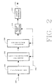
- Figure 2 is a functional block diagram illustrating the basic functional structure of a decoder incorporating a preferred embodiment of the present invention.
- Figure 3 is a flowgraph illustrating the forward pre-transform function applied to a 16-sample time-domain signal sample block to form an 8-sample modified sample block for a basic embodiment of the present invention permitting implementation of an E-TDAC transform analysis filter bank by a DCT and DST.
- Figure 4 is a flowgraph illustrating the forward pre-transform function applied to a 16-sample time-domain signal sample block to form an 8-sample modified sample block for an alternative embodiment of the present invention permitting implementation of an E-TDAC transform analysis filter bank by a DFT.
- Figure 5 is a hypothetical graphical representation illustrating the time-reversal regions of the time-domain aliasing component created by the E-TDAC transform using the conventional TDAC phase term.
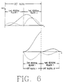
- Figure 6 is a hypothetical graphical representation illustrating the time-reversal regions of the time-domain aliasing component created by the E-TDAC transform using the TDAC phase term required to cancel time-domain aliasing in an N-sample length block overlapped with a subsequent 1 ⁇ 2 N -sample length block.
- Figure 7 is a hypothetical graphical representation illustrating the boundary between time-reversal regions of the time-domain aliasing component in a 1 ⁇ 4 N -sample length block.
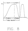
- Figure 8 is a hypothetical graphical representation of a bridge transform illustrating the time-reversal regions of the time-domain aliasing component.
- Figure 9 is a flowgraph illustrating the forward pre-transform function applied to a 16-sample time-domain signal sample block to form an 8-sample modified sample block permitting implementation of an adaptive-length E-TDAC transform analysis filter bank by a DCT and DST.
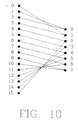
- Figure 10 is a flowgraph illustrating the forward pre-transform function applied to a 16-sample time-domain signal sample block to form an 8-sample modified sample block permitting implementation of an adaptive-length O-TDAC transform analysis filter bank by a DST.
- FIG. 1 illustrates the basic functional structure of a transform-based encoder incorporating an embodiment of the present invention.
- an encoder comprises buffer 102 which buffers input samples received from input path 100 into time-domain signal sample blocks, forward pre-transform 106 which generates modified samples by combining pairs of signal samples received from buffer 102 and in response to information received from path 104 establishing the number of signal samples constituting a time-domain signal sample block, forward transform 108 Which transforms the modified samples into frequency-domain transform coefficients by applying a transform whose length is adapted in response to information received from path 104, forward post-transform 110 which generates spectral information from the frequency-domain transform coefficients and in response to the information received from path 104, and formatter 112 which assembles digital information including the spectral information into a form suitable for transmission or storage along path 114.
- the functions performed by buffer 102 and formatter 112 are not discussed in detail herein.
- Figure 2 illustrates the basic functional structure of a transform-based decoder incorporating an embodiment of the present invention.
- a decoder comprises deformatter 202 which extracts spectral information and information establishing the inverse transform length from the encoded digital signal received from path 200, inverse pre-transform 206 which generates frequency-domain transform coefficients from the extracted spectral information and in response to the information establishing the inverse transform length received along path 204, inverse transform 208 which transforms the frequency-domain transform coefficients into time-domain transform coefficients by applying a transform whose length is in response to information received from path 204, inverse post-transform 210 which generates signal samples from the time-domain transform coefficients and in response to information received from path 204, and output processor 212 which generates along path 214 output samples corresponding to the input samples to a companion encoder in response to the signal samples.
- the functions performed by deformatter 202 and output processor 212 are not discussed in detail herein.
- a basic embodiment of the present invention is introduced in some detail before alternative embodiments are discussed.
- This basic embodiment uses fixed-length E-TDAC transforms to implement the analysis and synthesis filter banks. Preferred embodiments of various features are described throughout the discussion.
- a buffer represented by box 102 in Figure 1, receives signal samples and groups them into a sequence of time-domain signal sample blocks. Each block comprises N signal samples.
- the signal samples may be received from the sampling of an analog signal, from the generation of samples representing or simulating an analog signal, or from any other source of discrete-valued samples which correspond to a time-domain signal.
- filter selectivity may be affected significantly by weighting the time-domain signal samples by a weighting function commonly called a window. See generally, Harris, “On the Use of Windows for Harmonic Analysis with the Discrete Fourier Transform," Proc. IEEE , vol. 66, January, 1978, pp. 51-83.
- the E-TDAC transform used in the basic embodiment of the present invention requires window weighting, both weighting of the time-domain signal samples in an encoder prior to forward transform filtering, referred to as analysis windowing, and weighting of the recovered time-domain signal samples in a decoder after inverse transform filtering, referred to as synthesis windowing.
- analysis windowing weighting of the time-domain signal samples in an encoder prior to forward transform filtering
- synthesis windowing weighting of the recovered time-domain signal samples in a decoder after inverse transform filtering
- the forward transform is represented by box 108 in Figure 1.
- the E-TDAC transform used in the basic embodiment of the present invention is equivalent to the alternate application of a Modified Discrete Cosine Transform (MDCT) with a Modified Discrete Sine Transform (MDST).
- MDCT Modified Discrete Cosine Transform
- MDST Modified Discrete Sine Transform
- Each set of coefficients generated by the MDCT and the MDST are referred to herein as MDCT coefficient sets and MDST coefficient sets, respectively.
- the E-TDAC technique can accurately recover an input signal from an alternating sequence of overlapped fixed-length MDCT coefficient sets and MDST coefficient sets of the form ⁇ C(k) ⁇ 0 , ⁇ S(k) ⁇ 1 , ⁇ C(k) ⁇ 2 , ⁇ S(k) ⁇ 3 ,....
- the phase term m in equations 1 and 2 controls the phase shift of the time-domain aliasing distortion.
- E-TDAC requires the aliasing to be as follows: for the MDCT, the time-domain alias component consists of the first half of the sampled and windowed signal reversed in time about the one-quarter point of the sample block and the second half of the sampled and windowed signal reversed in time about the three-quarter point of the sample block; for the MDST, the alias component is similar to that for the MDCT except its amplitude is inverted in sign.
- the processing requirements of the technique used to evaluate the MDCT and the MDST may be reduced by applying a forward pre-transform function to the time-domain signal sample blocks to produce blocks of modified samples, and applying a 1 ⁇ 2 N -point DCT and a 1 ⁇ 2 N -point DST to the modified sample blocks for the N -point MDCT and MDST, respectively.
- the forward pre-transform function is represented by box 106 in Figure 1.
- the pre-transform function combines pairs of signal samples in each time-domain signal sample block of length N to produce a block of modified samples of length 1 ⁇ 2 N .
- Equation 1 The mathematical basis for using a 1 ⁇ 2 N -point DCT applied to modified samples to perform the N-point MDCT may be seen by first substituting equation 6 for the phase term m into equation 1.
- the MDST of length N can be implemented by a DST of length 1 ⁇ 2 N ;
- the forward pre-transform function for this basic embodiment can be performed by any of several implementations including software-controlled processors and circuits capable of combining pairs of time-domain signal samples to form modified samples.
- FIG 3 illustrates the forward pre-transform functions of equations 9 and 12 for a basic embodiment of the present invention.
- the minus signs shown within parenthesis denote terms which are subtractively combined with an associated sample for the function shown above in equation 12. This subtractive combination may be accomplished in circuitry, for example, by negating the value of the signal sample representations corresponding to the nodes in Figure 3 with minus signs in parenthesis and additively combining the resultant representations.
- the forward transform in the basic embodiment of the present generates frequency-domain transform coefficients in response to an input signal which are equivalent to the coefficients generated by an E-TDAC transform applied to the same input signal.
- Some alternative embodiments of the present invention described below require application of a forward post-transform function to the coefficients generated by the forward transform in order to obtain spectral information equivalent to transform coefficients generated by a corresponding TDAC transform.
- an encoder incorporating any embodiment of the present invention need not apply a forward post-transform function to the frequency-domain transform coefficients generated by the forward transform.
- the frequency-domain transform coefficients themselves may be directly transmitted or stored and subsequently transmitted to a corresponding receiver for decoding.
- spectral information is required.
- encoder/decoder systems which exploit psychoacoustic principles to reduce coded signal information requirements usually require spectral information in order to estimate psychoacoustic masking effects of a signal's spectral components.
- Frequency-domain transform coefficients generated by the forward transform and spectral information generated by the various forward post-transform functions described below are generally not suitable for low bit-rate transmission or efficient storage.
- Various quantization techniques may be used to reduce informational requirements by taking advantage of a signal's irrelevancy.
- the forward post-transform function represented by box 110 in Figure 1 may comprise quantizing the frequency-domain transform coefficients generated by the forward transform; however, quantizing is not required to practice the present invention.
- Output formatting represented by box 112 in Figure 1 is not required to practice the present invention but is often used in signal encoding applications. Generally, output formatting assembles the spectral information and other information required for transmission or storage. Any additional side-information needed by a decoder is also assembled into the formatted signal. Frame synchronization bits and error detection/correction codes may be used as needed for transmission. Database pointers or keys may be added as needed for storage. The formatted data is ready for transmission or for storage along path 114 shown in Figure 1.
- Input deformatting represented by box 202 in Figure 2 is not required to practice the present invention but is often used in signal decoding applications. Deformatting extracts spectral information and any side information from a formatted signal received from path 200 either by receipt of a transmitted signal or retrieved from storage.
- the inverse pre-transform function obtaineds frequency-domain transform coefficients from the spectral information in the received signal. If the spectral information in the received signal substantially corresponds to the frequency-domain transform coefficients generated by an E-TDAC transform, then the inverse pre-transform function in a basic embodiment of the present function may be a trivial or essentially null function such as, for example, grouping spectral information into blocks.
- the inverse pre-transform function may comprise dequantizing the encoded digital information into a form suitable for input to the inverse transform filter bank; however, dequantizing is not required to practice the present invention.
- Box 208 in Figure 2 represents a bank of synthesis filters which transforms each set of frequency-domain transform coefficients into time-domain transform coefficients.
- a transform inverse to that used in analysis filter bank 108 in Figure 1 implements synthesis filter bank 208.
- the inverse discrete transforms for E-TDAC used in the basic embodiment of the present invention is an alternating application of an Inverse Modified Discrete Cosine Transform (IMDCT) and an Inverse Modified Discrete Sine Transform (IMDST) shown in equations 13 and 14, respectively; where
- IMDCT Inverse Modified Discrete Cosine Transform
- IMDST Inverse Modified Discrete Sine Transform
- the processing requirements of the technique used to evaluate the IMDCT and the IMDST may be reduced by instead evaluating an Inverse DCT (IDCT) and an Inverse DST (IDST) and applying an inverse post-transform function after application of the inverse transforms.
- This inverse post-transform function is represented by box 210 in Figure 2.
- the inverse post-transform function splits time-domain transform coefficients into signal samples.
- An overlap-add process is required by the TDAC transforms to generate samples corresponding to signal samples encoded by a companion encoder. This process, represented by box 212 in Figure 2, overlaps adjacent blocks of recovered time-domain samples and adds the samples in one block to samples in the adjacent overlapped block.
- the E-TDAC transform used in the basic embodiment of the present invention also requires prior to overlap-add the application of a synthesis window to the recovered time-domain sample blocks.
- the constraints the E-TDAC transform places upon the design of the synthesis window, the analysis window, and the overlap-add process is discussed fully in the paper by Princen and Bradley referred to above.
- the forward E-TDAC transform is implemented by a Discrete Fourier Transform (DFT).
- DFT Discrete Fourier Transform
- a forward pre-transform function generates an alternating sequence of two types of blocks comprising modified samples; one block type comprising modified samples p(n) and a second block type comprising modified samples r(n). Each modified sample is formed from the combination of one pair of signal samples x(n) according to A flowgraph for a 16-sample block illustrating this forward pre-transform function is shown in Figure 4.
- the inverse E-TDAC transform is implemented by an Inverse DFT (IDFT).
- IDFT Inverse DFT
- An inverse pre-transform function recovers spectral information ⁇ (k) and ⁇ (k) corresponding to E-TDAC transform coefficients C(k) and S(k) , respectively, from the encoded signal and generates in response to the recovered spectral information an alternating sequence of two types of blocks comprising recovered frequency-domain transform coefficients; one block type comprises recovered complex-valued coefficients P ⁇ (k) of the form T ⁇ (k)+ j ⁇ (k) and a second block type comprises recovered complex-valued coefficients R ⁇ (k) of the form V ⁇ (k)+ j ⁇ (k).
- An inverse transform generates an alternating sequence of two types of blocks comprising recovered time-domain transform coefficients by applying an IDFT to the alternating sequence of frequency-domain transform coefficient blocks; one block type comprises recovered time-domain transform coefficients p ⁇ (k) and a second block type comprises recovered time-domain transform coefficients r ⁇ (k).
- the IDFT used to recover the time-domain transform coefficients is shown in equations 31 and 32;
- Recovered time-domain signal samples x ⁇ (n) are obtained by applying an inverse post-transform function to the alternating sequence of blocks comprising recovered time-domain transform coefficients.
- the MDCT and the MDST of one or more forward E-TDAC transforms are implemented concurrently by one or more DFTs.
- two adjacent frequency-domain coefficient sets as illustrated in expression 5 above may be generated concurrently by a single DFT.
- a MDCT coefficient set for channel one may be generated concurrently with a MDST coefficient set for channel two, immediately followed by a MDST coefficient set for channel one generated concurrently with a MDCT coefficient set for channel two.
- Other combinations of coefficient sets for concurrent processing are possible.
- concurrent transforms see generally, Brigham, The Fast Fourier Transform, Englewood Cliffs, NJ: Prentice-Hall, Inc., 1974, pp. 166-67.
- a forward pre-transform function generates a sequence of blocks comprising complex-valued modified samples q(n) of the form p(n)+ j ⁇ r(n) where p(n) and r(n) are formed from the application of the forward pre-transform function described above and shown in equations 21 and 22.
- the MDCT and the MDST constituting the forward E-TDAC transform are concurrently implemented by a DFT which generates complex-valued frequency-domain transform coefficients Q(k) of the form G(k)+ j ⁇ H(k) according to
- Spectral information corresponding to E-TDAC transform coefficients C(k) and S(k) is obtained by applying the forward post-transform functions according to
- the IMDCT and the IMDST of one or more inverse E-TDAC transforms are implemented concurrently by one or more IDFTs.
- the IMDCT and the IMDST constituting the inverse E-TDAC transform are concurrently implemented by an IDFT which generates complex-valued time-domain transform coefficients q ⁇ (n) of the form p ⁇ (n)+ j ⁇ r ⁇ (n) according to
- Time-domain signal samples x ⁇ (n) are recovered from the application of the inverse post-transform function described above and shown in equations 33 through 36.
- FIG. 5 is a hypothetical graphical representation of two adjacent overlapped N-sample length time-domain signal sample blocks recovered by an inverse E-TDAC transform, one block recovered from the IMDCT and the second block recovered from the IMDST after synthesis windowing but before overlap-add of the adjacent blocks has cancelled time-domain aliasing.
- the representation in this and other figures does not show individual signal samples, but rather illustrates only the envelope of the amplitude of samples within the windowed signal sample blocks.
- Each recovered signal sample block comprises two components: one component represented in the figures by a solid line substantially corresponds to the analysis- and synthesis-window weighted input signal samples, and the second component represented in the figures by a broken line corresponds to the analysis- and synthesis-window weighted time-domain aliasing distortion.
- the aliasing component is a time-reversed replica of the windowed input signal samples which occurs in two separate regions.
- the phase term m for the E-TDAC and the O-TDAC transforms controls the location of the boundary between these two regions. For fixed-length E-TDAC and O-TDAC transforms, the boundary is located at the mid-point of the signal sample block.
- the phase term required for time-domain aliasing cancellation under this condition is shown in equation 6.
- Figure 6 is a hypothetical graphical representation of three time-domain signal sample blocks recovered from an inverse E-TDAC transform prior to overlap-add.
- the first block is an N -sample length block which has been recovered from the IMDCT.
- the second and third blocks are 1 ⁇ 2 N -sample length blocks which have been recovered from the IMDST.
- the aliasing component in the N -sample length MDCT block comprises a replica of the first half of the signal sample block reversed in time about the one-quarter point of the sample block, and a replica of the second half of the sampled signal reversed in time about the three-quarter point of the sample block.
- the time-domain aliasing component in the first MDST 1 ⁇ 2 N -sample length block must be a replica of the entire 1 ⁇ 2 N -sample length block inverted in sign and time-reversed end-for-end.
- Figure 7 illustrates two window-weighted time-domain signal sample blocks.
- the right-hand block is 1 ⁇ 4 N samples in length.
- the boundary between time-reversal regions is at a point N/8 samples from the right-hand or trailing edge of the block.
- a bridge transform is a transform which bridges a shift from one transform length to another. For example, as shown in Figure 8, suppose the present invention is called upon to process one block of 1 ⁇ 2 N samples followed by another block of 1 ⁇ 4 N samples. It is possible to perform a separate transform for each block. For reasons whose explanation exceed the scope of this discussion, a bridge transform improves coder performance by instead transforming a single block of 3 / 4 N samples.
- the bridge transform required to process the 3 / 4 N -sample block shown in Figure 8 may be implemented by an FFT to compute the transform for three 1 ⁇ 4N blocks followed by a recombination operation.
- This technique is known in the art and is discussed in Oppenheim and Schafer, Digital Signal Processing , Englewood Cliffs, N.J.: Prentice-Hall, Inc., 1975, pp. 307-14.
- the FFT with this recombination operation can also be used to concurrently process two E-TDAC bridge transforms in the same manner as that briefly discussed above for fixed-length transforms. It is important to note, however, that concurrent processing in E-TDAC is possible only for a MDCT and MDST which have the same length and TDAC phase term.
- the length of the inverse transform may be established by side-information passed by the encoder in the encoded signal.
- each adaptive-length embodiment is substantially the same as that for a corresponding fixed-length embodiment.
- the most significant differences pertain to the pre- and post-transform functions and to the length and phase terms of the transform functions.
- each time-domain signal sample block is defined to be a + b samples in length, overlapping the immediately prior block by a samples and overlapping the immediately subsequent block by b samples. It is assumed that the number of samples in the two overlap intervals may vary from block to block. According to the conventions established in the previous discussion, the bridge transform applied to each time-domain signal sample block is an adaptive-length (a + b) -point transform.
- One adaptive-length embodiment corresponds to the fixed-length basic embodiment discussed above.
- the forward transform comprises a DCT and a DST according to
- the inverse transform comprises an IDCT and an IDST according to
- Another adaptive-length embodiment corresponds to the fixed-length embodiment of the E-TDAC transform implemented by a DFT, discussed above.
- the forward pre-transform corresponding to the functions shown in equations 21 and 22 for the fixed-length embodiment, generates an alternating sequence of modified sample blocks according to
- the forward E-TDAC transform is implemented by a DFT which generates alternating sets of complex-valued frequency-domain transform coefficients P(k) of the form T(k) +j ⁇ U(k) and R(k) of the form V(k) +j ⁇ W(k) in response to the alternating sequence of modified sample blocks according to
- the inverse pre-transform function corresponding to the functions shown in equations 27 through 30 for the fixed-length embodiment, generates an alternating sequence of blocks comprising recovered frequency-domain transform coefficients; one block type comprises recovered complex-valued coefficients P ⁇ (k) of the form T ⁇ (k)+ j ⁇ (k) and a second block type comprises recovered complex-valued coefficients R ⁇ (k) of the form V ⁇ (k)+ j ⁇ (k).
- the inverse transform generates an alternating sequence of two types of blocks comprising recovered time-domain transform coefficients by applying an IDFT to the alternating sequence of frequency-domain transform coefficient blocks; one block type comprises recovered time-domain transform coefficients p ⁇ (k) and a second block type comprises recovered time-domain transform coefficients r ⁇ (k) .
- the IDFT used to obtain the recovered time-domain transform coefficients is shown in equations 64 and 65;
- the processing requirements needed to implement this transform can be reduced by applying a forward pre-transform function to the time-domain signal samples to generate modified samples e(n), then applying a DST to the modified samples to generate frequency-domain transform coefficients X(k) .
- the forward transform comprises a DST according to
Abstract
Description
- The invention relates in general to digital encoding and decoding of information. More particularly, the invention relates to efficient implementation of digital analysis and synthesis filter banks used in digital encoding and decoding. In a preferred embodiment of the invention, the length of the filter bank used to implement critically-sampled analysis and synthesis filter banks may be adaptively selected.
- Throughout the following discussion and especially in the background discussion, more particular mention will be made of audio applications; however, it should be understood that the present invention is applicable to a range of applications wider than just that of audio encoding and decoding.
- There is considerable interest among those in the field of signal processing to develop efficient means to transmit or store information. Improving coding efficiency includes (1) reducing informational requirements, that is, reducing the amount of information required to adequately represent a signal during transmission or storage, and (2) reducing processing requirements, that is, reducing the amount of processing required to implement the encoding and decoding processes.
- In high-quality audio coding applications, informational requirements can sometimes be reduced without loss of perceptible audio quality by exploiting various psychoacoustic effects. Signal recording, transmitting, or reproducing techniques which divide the useful signal bandwidth into narrow bands with bandwidths approximating the human ear's critical bands can exploit psychoacoustic masking effects. Such techniques divide the signal bandwidth with an analysis filter bank, process the signal passed by each filter band, and reconstruct a replica of the original signal with a synthesis filter bank.
- Two common coding techniques are subband coding and transform coding. Subband coders and transform coders can reduce the informational requirements in particular frequency bands where the noise caused by the resulting coding inaccuracy is psychoacoustically masked. Subband coders may be implemented by a bank of digital bandpass filters defining subbands of varying bandwidth. Transform coders may be implemented by any of several time-domain to frequency-domain transforms. One or more adjacent transform coefficients are grouped together to define "subbands" having effective bandwidths which are sums of individual transform coefficient bandwidths.
- The mathematical basis for digital subband filter banks and digital block transforms is essentially the same. See Tribolet and Crochiere, "Frequency Domain Coding of Speech," IEEE Trans. Acoust., Speech, and Signal Proc., ASSP-27, October, 1979, pp. 512-30. Therefore, throughout the following discussion the concepts associated with terms such as "subband coder" and "transform coder" generally apply to both a true subband coder and a transform coder. The term "subband" refers to portions of the useful signal bandwidth whether implemented by a true subband coder or a transform coder. The terms "transform" and "transforming" include digital filters and digital filtering, respectively.
- In most digital coding applications, processing requirements can be reduced by increasing the efficiency of subband filtering. Improved processing efficiency permits implementation of encoders and decoders which are less expensive to build, or which impose lower signal propagation delays through an encoder/decoder system.
- In many transform coder systems, the analysis and synthesis filter banks are implemented by discrete time-domain to frequency-domain transforms such as the Discrete Fourier Transform (DFT), the Discrete Cosine Transform (DCT), and the Discrete Sine Transform (DST). The number of time domain signal samples, referred to herein as the time-domain signal sample block length, processed by such transforms is sometimes called the transform length, and the amount of processing required to perform these transforms is generally proportional to the square of the time-domain signal sample block length.
- The number of frequency-domain transform coefficients generated by a transform is also sometimes called the transform length. It is common for the number of frequency-domain transform coefficients generated by the transform to be equal to the time-domain signal sample block length, but this equality is not necessary. For example, one transform referred to herein as the E-TDAC transform is sometimes described in the art as a transform of length N that transforms signal sample blocks with a length of 2N samples. It is possible, however, to also describe the transform as one of length N which generates only ½N unique frequency-domain transform coefficients. Thus, in this discussion the time-domain signal sample block length and the discrete transform length are generally assumed to be synonyms.
- Various techniques have been utilized to reduce the amount of time required to perform a transform, or to reduce the processing power required to perform a transform in given amount of time, or both. One technique is taught in Narasimha and Peterson, "On the Computation of the Discrete Cosine Transform," IEEE Trans. on Communications, COM-26, June, 1978, pp. 934-36. Briefly, this technique evaluates an N-point DCT by rearranging or "shuffling" the samples representing the input signal, performing an N-point DFT on the shuffled samples, and multiplying the result with a complex function. It is approximately twice as efficient as other techniques using a 2N-point FFT; however, Narasimha and Peterson only teach how to improve the efficiency of filter banks implemented by one particular DCT.
- Another technique which yields approximately a two-fold increase in processing efficiency concurrently performs two real-valued discrete transforms of length N with a single complex-valued FFT of length N. A transform coder utilizing this technique to concurrently perform a modified DCT with a modified DST is described in International Patent Application PCT/US 91/02512, Publication No. WO 91/16769 (published October 31, 1991). The significance of these particular modified DCT and modified DST is discussed in Princen and Bradley, "Analysis/Synthesis Filter Bank Design Based on Time Domain Aliasing Cancellation," IEEE Trans. on Acoust., Speech, Signal Proc., ASSP-34, 1986, pp. 1153-1161. The authors describe a specific application of these transforms as the time-domain equivalent of an evenly-stacked critically-sampled single-sideband analysis-synthesis system. They are referred to collectively herein as the Evenly-stacked Time-Domain Aliasing Cancellation (E-TDAC) transform.
- Another technique to reduce processing requirements is taught by Malvar, "Lapped Transforms for Efficient Transform/Subband Coding," IEEE Trans. Acoust., Speech, Signal Proc., ASSP-38, June, 1980, pp. 969-78. This technique implements an N-point modified DCT by performing a ½N-point DST after combining pairs of the samples representing the input signal, or "folding" the N input signal samples into a smaller set of ½N points. It is approximately twice as efficient as performing the modified DCT in a straight-forward manner; however, Malvar only teaches how to fold input samples for a filter bank implemented by one specific modified DCT whose input samples have been weighted by a specific sine-tapered analysis window.
- The specific modified DCT implemented by Malvar is discussed in greater detail by Princen, Johnson, and Bradley, "Subband/Transform Coding Using Filter Bank Designs Based on Time Domain Aliasing Cancellation," ICASSP 1987 Conf. Proc., May 1987, pp. 2161-64. The authors describe this transform as the time-domain equivalent of an oddly-stacked critically sampled single-sideband analysis-synthesis system. It is referred to herein as the Oddly-stacked Time-Domain Aliasing Cancellation (O-TDAC) transform.
- It is desirable to implement encoders and decoders with the ability to use different time-domain signal sample block lengths in order to optimize coder performance. It is well known in the art that longer time-domain signal sample block lengths improve the selectivity or frequency-resolving power of transform coders, and better filter selectivity generally improves the ability of a transform coder to exploit psychoacoustic masking effects.
- But longer time-domain signal sample block lengths degrade the time-resolution of a subband filter bank. Inadequate time-resolution can produce audible distortion artifacts when quantizing errors of signal events, such as transients, producing pre-transient and post-transient ringing which exceed the ear's temporal psychoacoustic masking interval. Hence, it is desirable that techniques which improve subband filter bank processing efficiency should also permit adaptive selection of the time-domain signal sample block length.
- The importance of time-domain signal sample block length and its effect upon filter bank frequency-domain resolution and time-domain resolution is discussed in more detail in International Patent Application PCT/US 91/02512, Publication No. WO 91/16769, cited above, which is hereby incorporated by reference in its entirety.
- It is an object of the present invention to provide for a subband/transform encoder and a subband/transform decoder of digital information by means of analysis filtering and synthesis filtering requiring lower processing requirements, or imposing lower processing delays, or both.
- It is another object of the present invention to provide for a subband/transform encoder and a subband/transform decoder of digital information requiring lower processing requirements, or imposing lower processing delays, or both, by means of analysis filtering and synthesis filtering permitting adaptive selection of the filter-bank length.
- The above objects are achieved with the means as claimed in the independent claims.
- Further details of the above objects and still other objects of the invention are set forth throughout this document, particularly in the Modes for Carrying Out the Invention, below. Although the invention is more particularly described for audio encoding and decoding applications, it should be appreciated that the invention is much broader and may be applied to other applications. Throughout this Description, discussion of encoders incorporating the present invention also pertains more generally to signal-analysis filtering applications, and discussion of decoders incorporating the present invention pertains more generally to signal-synthesis filtering applications.
- In accordance with the teachings of the present invention in one embodiment, an encoder provides for the encoding of input signal samples representing a time-domain signal. The input samples which are weighted by an analysis-window function are buffered into time-domain signal sample blocks. Pairs of signal samples in the time-domain signal sample blocks are combined by a forward pre-transform function to generate modified samples. Frequency-domain transform coefficients are generated by applying a discrete digital transform to the modified samples. Spectral information is generated by applying a forward post-transform function to the frequency-domain transform coefficients.
- Also in accordance with the teachings of the present invention in one embodiment, a decoder provides for the decoding of digitally encoded spectral information. Frequency-domain transform coefficients are generated by applying an inverse pre-transform function to the spectral information. Time-domain transform coefficients are generated by applying an inverse discrete digital transform to the frequency-domain transform coefficients. Time-domain signal sample blocks are generated by applying an inverse post-transform function to the time-domain transform coefficients, and output samples which correspond to the input samples to a companion encoder are generated by overlapping and adding samples in adjacent time-domain signal sample blocks.
- The various features of the present invention and its preferred embodiments are set forth in greater detail in the following Modes for Carrying Out the Invention and in the accompanying drawings.
- Figure 1 is a functional block diagram illustrating the basic functional structure of an encoder incorporating a preferred embodiment of the present invention.
- Figure 2 is a functional block diagram illustrating the basic functional structure of a decoder incorporating a preferred embodiment of the present invention.
- Figure 3 is a flowgraph illustrating the forward pre-transform function applied to a 16-sample time-domain signal sample block to form an 8-sample modified sample block for a basic embodiment of the present invention permitting implementation of an E-TDAC transform analysis filter bank by a DCT and DST.
- Figure 4 is a flowgraph illustrating the forward pre-transform function applied to a 16-sample time-domain signal sample block to form an 8-sample modified sample block for an alternative embodiment of the present invention permitting implementation of an E-TDAC transform analysis filter bank by a DFT.
- Figure 5 is a hypothetical graphical representation illustrating the time-reversal regions of the time-domain aliasing component created by the E-TDAC transform using the conventional TDAC phase term.
- Figure 6 is a hypothetical graphical representation illustrating the time-reversal regions of the time-domain aliasing component created by the E-TDAC transform using the TDAC phase term required to cancel time-domain aliasing in an N-sample length block overlapped with a subsequent ½N-sample length block.
- Figure 7 is a hypothetical graphical representation illustrating the boundary between time-reversal regions of the time-domain aliasing component in a ¼N-sample length block.
- Figure 8 is a hypothetical graphical representation of a bridge transform illustrating the time-reversal regions of the time-domain aliasing component.
- Figure 9 is a flowgraph illustrating the forward pre-transform function applied to a 16-sample time-domain signal sample block to form an 8-sample modified sample block permitting implementation of an adaptive-length E-TDAC transform analysis filter bank by a DCT and DST.
- Figure 10 is a flowgraph illustrating the forward pre-transform function applied to a 16-sample time-domain signal sample block to form an 8-sample modified sample block permitting implementation of an adaptive-length O-TDAC transform analysis filter bank by a DST.
- Figure 1 illustrates the basic functional structure of a transform-based encoder incorporating an embodiment of the present invention. According to this structure, an encoder comprises
buffer 102 which buffers input samples received frominput path 100 into time-domain signal sample blocks, forward pre-transform 106 which generates modified samples by combining pairs of signal samples received frombuffer 102 and in response to information received frompath 104 establishing the number of signal samples constituting a time-domain signal sample block, forward transform 108 Which transforms the modified samples into frequency-domain transform coefficients by applying a transform whose length is adapted in response to information received frompath 104, forward post-transform 110 which generates spectral information from the frequency-domain transform coefficients and in response to the information received frompath 104, andformatter 112 which assembles digital information including the spectral information into a form suitable for transmission or storage alongpath 114. The functions performed bybuffer 102 andformatter 112 are not discussed in detail herein. - Figure 2 illustrates the basic functional structure of a transform-based decoder incorporating an embodiment of the present invention. According to this structure, a decoder comprises
deformatter 202 which extracts spectral information and information establishing the inverse transform length from the encoded digital signal received frompath 200,inverse pre-transform 206 which generates frequency-domain transform coefficients from the extracted spectral information and in response to the information establishing the inverse transform length received alongpath 204,inverse transform 208 which transforms the frequency-domain transform coefficients into time-domain transform coefficients by applying a transform whose length is in response to information received frompath 204,inverse post-transform 210 which generates signal samples from the time-domain transform coefficients and in response to information received frompath 204, andoutput processor 212 which generates alongpath 214 output samples corresponding to the input samples to a companion encoder in response to the signal samples. The functions performed bydeformatter 202 andoutput processor 212 are not discussed in detail herein. - It should be appreciated from a study of the following disclosure and the accompanying claims that some elements shown in Figures 1 and 2 are not required to practice various embodiments of the present invention.
- A basic embodiment of the present invention is introduced in some detail before alternative embodiments are discussed. This basic embodiment uses fixed-length E-TDAC transforms to implement the analysis and synthesis filter banks. Preferred embodiments of various features are described throughout the discussion.
- A buffer, represented by
box 102 in Figure 1, receives signal samples and groups them into a sequence of time-domain signal sample blocks. Each block comprises N signal samples. The signal samples may be received from the sampling of an analog signal, from the generation of samples representing or simulating an analog signal, or from any other source of discrete-valued samples which correspond to a time-domain signal. - It is well known in the art that the frequency-resolving power or selectivity of a filter bank implemented by a discrete transform improves as the transform length increases. It is also well known that filter selectivity may be affected significantly by weighting the time-domain signal samples by a weighting function commonly called a window. See generally, Harris, "On the Use of Windows for Harmonic Analysis with the Discrete Fourier Transform," Proc. IEEE, vol. 66, January, 1978, pp. 51-83.
- The E-TDAC transform used in the basic embodiment of the present invention requires window weighting, both weighting of the time-domain signal samples in an encoder prior to forward transform filtering, referred to as analysis windowing, and weighting of the recovered time-domain signal samples in a decoder after inverse transform filtering, referred to as synthesis windowing. Analysis- and synthesis-window weighting are discussed below only briefly. It is assumed herein that the buffered signal samples are weighted by an analysis window as may be required or desired. Input signal samples may be weighted by an analysis window prior to or subsequent to their receipt by the buffer without departing from the scope of the present invention.
- Although the forward pre-transform function discussed below is applied to time-domain signal sample blocks prior to application of the forward transform, it is necessary to introduce the forward transform before the forward pre-transform function can be fully described. The forward transform is represented by
box 108 in Figure 1. - The E-TDAC transform used in the basic embodiment of the present invention is equivalent to the alternate application of a Modified Discrete Cosine Transform (MDCT) with a Modified Discrete Sine Transform (MDST). The MDCT and the MDST, shown in
equations 

- k = frequency-domain transform coefficient number,
- n = time-domain signal sample number,
- N = time-domain signal sample block length,
- m = phase term required for TDAC (see equation 6),
- x(n) = time-domain signal sample n,
- C(k) = MDCT frequency-domain transform coefficient k, and
- S(k) = MDST frequency-domain transform coefficient k.
- The E-TDAC transform produces one of two alternating sets of frequency-domain transform coefficients in response to each time-domain signal sample block. These sets of frequency-domain transform coefficients are of the form


- Princen and Bradley showed that with the proper phase term m and a suitable pair of analysis-synthesis windows, the E-TDAC technique can accurately recover an input signal from an alternating sequence of overlapped fixed-length MDCT coefficient sets and MDST coefficient sets of the form

- Using only the alternate MDCT coefficient sets and MDST coefficient sets produces a time-domain aliasing component, but the aliasing component may be cancelled by choosing the appropriate phase term m for
equations - The phase term m in
equations - The phase term required to produce the appropriate aliasing components for alias cancellation is

- The processing requirements of the technique used to evaluate the MDCT and the MDST may be reduced by applying a forward pre-transform function to the time-domain signal sample blocks to produce blocks of modified samples, and applying a ½N-point DCT and a ½N-point DST to the modified sample blocks for the N-point MDCT and MDST, respectively. The forward pre-transform function is represented by
box 106 in Figure 1. For E-TDAC, the pre-transform function combines pairs of signal samples in each time-domain signal sample block of length N to produce a block of modified samples of length ½N. - The mathematical basis for using a ½N-point DCT applied to modified samples to perform the N-point MDCT may be seen by first substituting
equation 6 for the phase term m intoequation 1. The MDCT inequation 1 may be expressed as


n+ 


equation 1 can be rewritten as


- From a similar derivation, it can be shown that the MDST of length N can be implemented by a DST of length ½N;


- It should be appreciated that the forward pre-transform function for this basic embodiment, as well as for alternative embodiments discussed below, can be performed by any of several implementations including software-controlled processors and circuits capable of combining pairs of time-domain signal samples to form modified samples. One flowgraph for a 16-sample block is shown in Figure 3 which illustrates the forward pre-transform functions of
equations equation 12. This subtractive combination may be accomplished in circuitry, for example, by negating the value of the signal sample representations corresponding to the nodes in Figure 3 with minus signs in parenthesis and additively combining the resultant representations. - In principle, the forward transform in the basic embodiment of the present generates frequency-domain transform coefficients in response to an input signal which are equivalent to the coefficients generated by an E-TDAC transform applied to the same input signal. Some alternative embodiments of the present invention described below require application of a forward post-transform function to the coefficients generated by the forward transform in order to obtain spectral information equivalent to transform coefficients generated by a corresponding TDAC transform.
- If an application does not require spectral information, then an encoder incorporating any embodiment of the present invention need not apply a forward post-transform function to the frequency-domain transform coefficients generated by the forward transform. For example, the frequency-domain transform coefficients themselves may be directly transmitted or stored and subsequently transmitted to a corresponding receiver for decoding.
- For many applications, however, spectral information is required. For example, encoder/decoder systems which exploit psychoacoustic principles to reduce coded signal information requirements usually require spectral information in order to estimate psychoacoustic masking effects of a signal's spectral components.
- Frequency-domain transform coefficients generated by the forward transform and spectral information generated by the various forward post-transform functions described below are generally not suitable for low bit-rate transmission or efficient storage. Various quantization techniques may be used to reduce informational requirements by taking advantage of a signal's irrelevancy.
- In a practical implementation of an encoder incorporating a basic embodiment of the present invention, the forward post-transform function represented by
box 110 in Figure 1 may comprise quantizing the frequency-domain transform coefficients generated by the forward transform; however, quantizing is not required to practice the present invention. - Output formatting represented by
box 112 in Figure 1 is not required to practice the present invention but is often used in signal encoding applications. Generally, output formatting assembles the spectral information and other information required for transmission or storage. Any additional side-information needed by a decoder is also assembled into the formatted signal. Frame synchronization bits and error detection/correction codes may be used as needed for transmission. Database pointers or keys may be added as needed for storage. The formatted data is ready for transmission or for storage alongpath 114 shown in Figure 1. - Input deformatting represented by
box 202 in Figure 2 is not required to practice the present invention but is often used in signal decoding applications. Deformatting extracts spectral information and any side information from a formatted signal received frompath 200 either by receipt of a transmitted signal or retrieved from storage. - The inverse pre-transform function, represented by
box 206 in Figure 2, obtains frequency-domain transform coefficients from the spectral information in the received signal. If the spectral information in the received signal substantially corresponds to the frequency-domain transform coefficients generated by an E-TDAC transform, then the inverse pre-transform function in a basic embodiment of the present function may be a trivial or essentially null function such as, for example, grouping spectral information into blocks. - In a practical implementation of a decoder incorporating a basic embodiment of the present invention, the inverse pre-transform function may comprise dequantizing the encoded digital information into a form suitable for input to the inverse transform filter bank; however, dequantizing is not required to practice the present invention.
-
Box 208 in Figure 2 represents a bank of synthesis filters which transforms each set of frequency-domain transform coefficients into time-domain transform coefficients. A transform inverse to that used inanalysis filter bank 108 in Figure 1 implementssynthesis filter bank 208. The inverse discrete transforms for E-TDAC used in the basic embodiment of the present invention is an alternating application of an Inverse Modified Discrete Cosine Transform (IMDCT) and an Inverse Modified Discrete Sine Transform (IMDST) shown inequations 

- Ĉ(k) = recovered MDCT frequency-domain transform coefficient k,
- Ŝ(k) = recovered MDST frequency-domain transform coefficient k, and
- x̂(n) = recovered time-domain signal sample n.
- The processing requirements of the technique used to evaluate the IMDCT and the IMDST may be reduced by instead evaluating an Inverse DCT (IDCT) and an Inverse DST (IDST) and applying an inverse post-transform function after application of the inverse transforms. This inverse post-transform function is represented by
box 210 in Figure 2. - For E-TDAC, the inverse post-transform function splits time-domain transform coefficients into signal samples. Using a derivation similar to that discussed above for the forward transform, it can be shown that, with an appropriate inverse post-transform function discussed below, the IMDCT of length N can be implemented by an IDCT of length ½N;


- Recovered time-domain signal samples x̂(n) may be obtained from the time-domain transform coefficients ŷ(n) according to


- With an appropriate inverse post-transform function, the IMDST of length N can be implemented by an IDST of length ½N;

- Recovered time-domain signal samples may be obtained from the time-domain transform coefficients ẑ(n) according to


- An overlap-add process is required by the TDAC transforms to generate samples corresponding to signal samples encoded by a companion encoder. This process, represented by
box 212 in Figure 2, overlaps adjacent blocks of recovered time-domain samples and adds the samples in one block to samples in the adjacent overlapped block. - The E-TDAC transform used in the basic embodiment of the present invention also requires prior to overlap-add the application of a synthesis window to the recovered time-domain sample blocks. The constraints the E-TDAC transform places upon the design of the synthesis window, the analysis window, and the overlap-add process is discussed fully in the paper by Princen and Bradley referred to above.
- Alternative embodiments of the present invention may achieve greater reductions in processing requirements. The following description discusses the differences between these alternative embodiments and the basic embodiment described above.
- In one alternative embodiment of the present invention for an encoder, the forward E-TDAC transform is implemented by a Discrete Fourier Transform (DFT).
- A forward pre-transform function generates an alternating sequence of two types of blocks comprising modified samples; one block type comprising modified samples p(n) and a second block type comprising modified samples r(n). Each modified sample is formed from the combination of one pair of signal samples x(n) according to


- The forward E-TDAC transform is implemented by a DFT which generates alternating sets of complex-valued frequency-domain transform coefficients P(k) of the form T(k)+j·U(k) and R(k) of the form V(k)+j·W(k) in response to the alternating sequence of modified sample blocks;


- Spectral information corresponding to E-TDAC transform coefficients C(k) and S(k) is obtained by applying a forward post-transform function according to;


- In one alternative embodiment of the present invention for a decoder, the inverse E-TDAC transform is implemented by an Inverse DFT (IDFT).
- An inverse pre-transform function recovers spectral information Ĉ(k) and Ŝ(k) corresponding to E-TDAC transform coefficients C(k) and S(k), respectively, from the encoded signal and generates in response to the recovered spectral information an alternating sequence of two types of blocks comprising recovered frequency-domain transform coefficients; one block type comprises recovered complex-valued coefficients P̂(k) of the form T̂(k)+j·Û(k) and a second block type comprises recovered complex-valued coefficients R̂(k) of the form V̂(k)+j·Ŵ(k). The real and imaginary parts of the frequency-domain transform coefficients are obtained according to


- An inverse transform generates an alternating sequence of two types of blocks comprising recovered time-domain transform coefficients by applying an IDFT to the alternating sequence of frequency-domain transform coefficient blocks; one block type comprises recovered time-domain transform coefficients p̂(k) and a second block type comprises recovered time-domain transform coefficients r̂(k). The IDFT used to recover the time-domain transform coefficients is shown in equations 31 and 32;


- Recovered time-domain signal samples x̂(n) are obtained by applying an inverse post-transform function to the alternating sequence of blocks comprising recovered time-domain transform coefficients. Signal samples are obtained from blocks comprising the p̂(k) coefficients according to


- In another embodiment of the present invention for an encoder, the MDCT and the MDST of one or more forward E-TDAC transforms are implemented concurrently by one or more DFTs. In single channel encoder applications, two adjacent frequency-domain coefficient sets as illustrated in
expression 5 above may be generated concurrently by a single DFT. In two channel applications, a MDCT coefficient set for channel one may be generated concurrently with a MDST coefficient set for channel two, immediately followed by a MDST coefficient set for channel one generated concurrently with a MDCT coefficient set for channel two. Other combinations of coefficient sets for concurrent processing are possible. For additional detail on concurrent transforms, see generally, Brigham, The Fast Fourier Transform, Englewood Cliffs, NJ: Prentice-Hall, Inc., 1974, pp. 166-67. - A forward pre-transform function generates a sequence of blocks comprising complex-valued modified samples q(n) of the form p(n)+j·r(n) where p(n) and r(n) are formed from the application of the forward pre-transform function described above and shown in equations 21 and 22.
- The MDCT and the MDST constituting the forward E-TDAC transform are concurrently implemented by a DFT which generates complex-valued frequency-domain transform coefficients Q(k) of the form G(k)+j·H(k) according to

- Spectral information corresponding to E-TDAC transform coefficients C(k) and S(k) is obtained by applying the forward post-transform functions according to


- In another embodiment of the present invention for a decoder, the IMDCT and the IMDST of one or more inverse E-TDAC transforms are implemented concurrently by one or more IDFTs.
- An inverse pre-transform function recovers spectral information Ĉ(k) and Ŝ(k) corresponding to E-TDAC transform coefficients C(k) and S(k), respectively, from the encoded signal and generates in response to the recovered spectral information a sequence of blocks comprising recovered complex-valued frequency-domain transform coefficients Q̂(k) of the form Ĝ(k)+j·Ĥ(k) where Ĝ(k) and Ĥ(k) are obtained from recovered spectral information according to


- The IMDCT and the IMDST constituting the inverse E-TDAC transform are concurrently implemented by an IDFT which generates complex-valued time-domain transform coefficients q̂(n) of the form p̂(n)+j·r̂(n) according to

- Time-domain signal samples x̂(n) are recovered from the application of the inverse post-transform function described above and shown in equations 33 through 36.
- As mentioned above, it is desirable that the technique which improves transform processing efficiency should also permit adaptive selection of the transform length. The means and considerations required to implement an adaptive-transform-length coder are not discussed here, but are discussed in International Patent Application PCT/US 91/02512, Publication No. WO 91/16769 (published October 31, 1991).
- Changes in the length of either the E-TDAC transform or the O-TDAC transform may require changes in the phase term m in order to realize time-domain aliasing cancellation. Figure 5 is a hypothetical graphical representation of two adjacent overlapped N-sample length time-domain signal sample blocks recovered by an inverse E-TDAC transform, one block recovered from the IMDCT and the second block recovered from the IMDST after synthesis windowing but before overlap-add of the adjacent blocks has cancelled time-domain aliasing. The representation in this and other figures does not show individual signal samples, but rather illustrates only the envelope of the amplitude of samples within the windowed signal sample blocks.
- Each recovered signal sample block comprises two components: one component represented in the figures by a solid line substantially corresponds to the analysis- and synthesis-window weighted input signal samples, and the second component represented in the figures by a broken line corresponds to the analysis- and synthesis-window weighted time-domain aliasing distortion. As discussed above, the aliasing component is a time-reversed replica of the windowed input signal samples which occurs in two separate regions. The phase term m for the E-TDAC and the O-TDAC transforms controls the location of the boundary between these two regions. For fixed-length E-TDAC and O-TDAC transforms, the boundary is located at the mid-point of the signal sample block. The phase term required for time-domain aliasing cancellation under this condition is shown in
equation 6. - Figure 6 is a hypothetical graphical representation of three time-domain signal sample blocks recovered from an inverse E-TDAC transform prior to overlap-add. The first block is an N-sample length block which has been recovered from the IMDCT. The second and third blocks are ½N-sample length blocks which have been recovered from the IMDST. The aliasing component in the N-sample length MDCT block comprises a replica of the first half of the signal sample block reversed in time about the one-quarter point of the sample block, and a replica of the second half of the sampled signal reversed in time about the three-quarter point of the sample block. If overlap-add of the second half of the MDCT block and the first MDST ½N-sample length block shown in Figure 6 is to cancel time-domain aliasing, the time-domain aliasing component in the first MDST ½N-sample length block must be a replica of the entire ½N-sample length block inverted in sign and time-reversed end-for-end. The phase term m required by the MDST and IMDST transforms to produce a time-domain aliasing component with these characteristics is m = ½.
- It can be shown that the phase term may be written generally as

- For example, Figure 7 illustrates two window-weighted time-domain signal sample blocks. The right-hand block is ¼N samples in length. Within this block, the boundary between time-reversal regions is at a point N/8 samples from the right-hand or trailing edge of the block. Thus, the phase term m required to cause time-reversal of the aliasing component within each region of the ¼N-sample block is

- With this background established, it is now possible to introduce the "bridge transform." A bridge transform is a transform which bridges a shift from one transform length to another. For example, as shown in Figure 8, suppose the present invention is called upon to process one block of ½N samples followed by another block of ¼N samples. It is possible to perform a separate transform for each block. For reasons whose explanation exceed the scope of this discussion, a bridge transform improves coder performance by instead transforming a single block of 3/4 N samples.
- The bridge transform required to process the 3/4 N-sample block shown in Figure 8 may be implemented by an FFT to compute the transform for three ¼N blocks followed by a recombination operation. This technique is known in the art and is discussed in Oppenheim and Schafer, Digital Signal Processing, Englewood Cliffs, N.J.: Prentice-Hall, Inc., 1975, pp. 307-14. The FFT with this recombination operation can also be used to concurrently process two E-TDAC bridge transforms in the same manner as that briefly discussed above for fixed-length transforms. It is important to note, however, that concurrent processing in E-TDAC is possible only for a MDCT and MDST which have the same length and TDAC phase term.
- For the decoder, the length of the inverse transform may be established by side-information passed by the encoder in the encoded signal. The same considerations for adaptive-length transforms and bridge transforms that were discussed above for the forward transform, including the phase term required for time-domain aliasing cancellation, also apply to the inverse transform.
- The following describes differences between adaptive-length embodiments of the present invention and the fixed-length embodiments discussed above. The structure of each adaptive-length embodiment is substantially the same as that for a corresponding fixed-length embodiment. The most significant differences pertain to the pre- and post-transform functions and to the length and phase terms of the transform functions.
- In the following discussions, each time-domain signal sample block is defined to be a+b samples in length, overlapping the immediately prior block by a samples and overlapping the immediately subsequent block by b samples. It is assumed that the number of samples in the two overlap intervals may vary from block to block. According to the conventions established in the previous discussion, the bridge transform applied to each time-domain signal sample block is an adaptive-length (a+b)-point transform.
- One adaptive-length embodiment corresponds to the fixed-length basic embodiment discussed above. The forward pre-transform, corresponding to the functions shown in
equations 

- The forward transform comprises a DCT and a DST according to


- The inverse transform comprises an IDCT and an IDST according to


- The inverse post-transform function, corresponding to the functions shown in equations 16, 17, 19, and 20 for the fixed-length embodiment, recovers time-domain signal samples from time-domain transform coefficients according to


- Another adaptive-length embodiment corresponds to the fixed-length embodiment of the E-TDAC transform implemented by a DFT, discussed above. The forward pre-transform, corresponding to the functions shown in equations 21 and 22 for the fixed-length embodiment, generates an alternating sequence of modified sample blocks according to


- The forward E-TDAC transform is implemented by a DFT which generates alternating sets of complex-valued frequency-domain transform coefficients P(k) of the form T(k)+j·U(k) and R(k) of the form V(k)+j·W(k) in response to the alternating sequence of modified sample blocks according to


- The forward post-transform, corresponding to the functions shown in equations 25 and 26 for the fixed-length embodiment, generates alternating sets of spectral information according to


- The inverse pre-transform function, corresponding to the functions shown in equations 27 through 30 for the fixed-length embodiment, generates an alternating sequence of blocks comprising recovered frequency-domain transform coefficients; one block type comprises recovered complex-valued coefficients P̂(k) of the form T̂(k)+j·Û(k) and a second block type comprises recovered complex-valued coefficients R̂(k) of the form V̂(k)+j·Ŵ(k). Each frequency-domain transform coefficient is obtained according to


- The inverse transform generates an alternating sequence of two types of blocks comprising recovered time-domain transform coefficients by applying an IDFT to the alternating sequence of frequency-domain transform coefficient blocks; one block type comprises recovered time-domain transform coefficients p̂(k) and a second block type comprises recovered time-domain transform coefficients r̂(k). The IDFT used to obtain the recovered time-domain transform coefficients is shown in equations 64 and 65;


- The inverse post-transform function, corresponding to the functions shown in equations 33 through 36 for the fixed-length embodiment, obtains recovered time-domain signal samples from recovered time-domain transform coefficients according to


- The O-TDAC transform utilizes a MDCT of the form

- The processing requirements needed to implement this transform can be reduced by applying a forward pre-transform function to the time-domain signal samples to generate modified samples e(n), then applying a DST to the modified samples to generate frequency-domain transform coefficients X(k). The forward pre-transform function is


- The forward transform comprises a DST according to

- The inverse transform comprises an IDST according to

Ê(k) = recovered frequency-domain transform coefficient k. - The inverse post-transform function obtains recovered time-domain signal samples x̂(n) from recovered time-domain transform coefficients according to


Claims (17)
- A signal-analysis system for the filtering of input samples representing one or more signals comprisinginput buffer means (102) for grouping said input samples into time-domain signal sample blocks of length N wherein said input samples are analysis-window weighted samples, andanalysis means for generating spectral information in response to said time-domain signal sample blocks, said spectral information comprising spectral coefficients C(k) and S(k) substantially corresponding to the frequency-domain transform coefficients of an Evenly-Stacked Time-Domain Aliasing Cancellation transform applied to said time-domain signal sample blocks. wherein said spectral coefficients C(k) and S(k) substantially correspond to Modified Discrete Cosine Transform coefficients and Modified Discrete Sine Transform coefficients, respectively,characterized in that said analysis means comprisesforward pre-transform means (106) for generating modified-sample blocks comprising ½N modified samples by combining one or more pairs of analysis-window weighted samples to form said modified samples, andforward transform means (108) for generating frequency-domain transform coefficients by applying one or more discrete transform functions to said modified-sample blocks.
- A signal-analysis system according to claim 1 whereinsaid forward pre-transform means (106) generates first modified-sample blocks comprising modified samples y(n) formed from the additive combination of a pair of analysis-window weighted samples x(n) from a respective one of said time-domain signal sample blocks according to

 said forward transform means (108) generates spectral coefficients C(k) by applying a discrete transform function substantially corresponding to a Discrete Cosine Transform function to said first modified-sample blocks and generates spectral coefficients S(k) by applying a discrete transform function substantially corresponding to a Discrete Sine Transform function to said second modified-sample blocks.
 - A signal-analysis system according to claim 1 whereinsaid forward pre-transform means (106) generates first modified-sample blocks comprising modified samples p(n) formed from the additive combination of a pair of analysis-window weighted samples x(n) from a respective one of said time-domain signal sample blocks according to

 said forward transform means (108) generates a first set of complex-valued frequency-domain transform coefficients P(k) of the form T(k)+j·U(k) by applying a discrete transform function substantially corresponding to a Discrete Fourier Transform to said first modified-sample blocks and generates a second set of complex-valued frequency-domain transform coefficients R(k) of the form V(k)+j·W(k) by applying a discrete transform function substantially corresponding to a Discrete Fourier Transform to said second modified-sample blocks, andwherein said analysis means further comprises forward post-transform means (110) for generating said spectral coefficients C(k) by applying a forward post-transform function to said first set of complex-valued frequency-domain transform coefficients according to

- A signal-analysis system according to claim 1 whereinsaid forward pre-transform means (106) generates said modified-sample blocks comprising complex-valued modified samples q(n) of the form p(n)+j·r(n) wherein each p(n) is formed from the additive combination of a pair of analysis-window weighted samples x(n) from a respective one of said time-domain signal sample blocks according to

 said forward transform means (108) generates a set of complex-valued frequency-domain transform coefficients Q(k) of the form G(k)+j·H(k) by applying a discrete transform substantially corresponding to a Discrete Fourier Transform to said modified-sample blocks, andwherein said analysis means further comprises forward post-transform means (110) for generating said spectral coefficients C(k) by applying a forward post-transform function to said set of complex-valued frequency-domain transform coefficients according to

- A signal-analysis system for the filtering of input samples representing one or more signals comprisinginput buffer means (102) for grouping said input samples into time-domain signal sample blocks of length (a+b), wherein said input samples are analysis-window weighted samples, andanalysis means for generating spectral information in response to said time-domain signal sample blocks, said spectral information comprising spectral coefficients substantially corresponding to the frequency-domain transform coefficients of either an Evenly-Stacked Time Domain Aliasing Cancellation transform or an Oddly-Stacked Time Domain Aliasing Cancellation transform of size (a+b),characterized in that said signal sample blocks are of length a+b wherein said length varies from block to block one or more times, and that said analysis means comprisesforward pre-transform means (106) for generating modified-sample blocks comprising ½(a+b) modified samples by combining pairs of analysis-window weighted samples to form said modified samples, andforward transform means (108) for generating frequency-domain transform coefficients by applying one or more discrete transform functions to said modified-sample blocks.
- A signal-analysis system according to claim 5 whereinsaid forward pre-transform means (106) generates first modified-sample blocks comprising modified samples y(n) formed from the additive combination of a pair of analysis-window weighted samples x(n) from a respective one of said time-domain signal sample blocks according to

 said forward transform means (108) generates spectral coefficients C(k) by applying a discrete transform function substantially corresponding to a Discrete Cosine Transform function to said first modified-sample blocks and generates spectral coefficients S(k) by applying a discrete transform function substantially corresponding to a Discrete Sine Transform function to said second modified-sample blocks.
 - A signal-analysis system according to claim 5 whereinsaid forward pre-transform means (106) generates first modified-sample blocks comprising modified samples p(n) formed from the additive combination of a pair of analysis-window weighted samples x(n) from a respective one of said time-domain signal sample blocks according to

 said forward transform means (108) generates a first set of complex-valued frequency-domain transform coefficients P(k) of the form T(k)+j·U(k) by applying a discrete transform function substantially corresponding to a Discrete Fourier Transform to said first modified-sample blocks and generates a second set of complex-valued frequency-domain transform coefficients R(k) of the form V(k)+j·W(k) by applying a discrete transform function substantially corresponding to a Discrete Fourier Transform to said second modified-sample blocks, andwherein said signal-analysis system further comprises forward post-transform means (110) for generating spectral coefficients C(k) by applying a forward post-transform function to said first set of complex-valued frequency-domain transform coefficients according to

- A signal-analysis system according to claim 5 whereinsaid forward pre-transform means (106) generates said modified-sample blocks comprising modified samples e(n) formed from the combination of a pair of analysis-window weighted samples x(n) from a respective one of said time-domain signal sample blocks according to

 said forward transform means (108) generates said spectral information by applying a discrete transform function substantially corresponding to a Discrete Sine Transform function to said modified-sample blocks.
 - A signal-synthesis system for the inverse filtering of spectral information representing one or more digital signals comprisingsynthesis means for generating signal samples in response to said spectral information, said signal samples substantially corresponding to the time-domain transform coefficients of length N of an inverse Evenly-Stacked Time-Domain Aliasing Cancellation transform applied to said spectral information, andoutput means (212) for generating output samples by overlapping pairs of said time-domain signal sample blocks and additively combining signal samples from each of said overlapped blocks,characterized in that said synthesis means comprisesinverse pre-transform means (206) for generating sets of frequency-domain transform coefficients in response to said spectral information,inverse transform means (208) for generating transform blocks comprising time-domain transform coefficients by applying an inverse discrete transform function to said sets of frequency-domain transform coefficients, andinverse post-transform means (210) for generating time-domain signal sample blocks comprising N signal samples, wherein one or more pairs of signal samples are generated from a respective one of said time-domain transform coefficients.
- A signal-synthesis system according to claim 9 whereinsaid inverse transform means (208) generates transform blocks comprising time-domain transform coefficients ŷ(n) by applying an inverse discrete transform function substantially corresponding to an Inverse Discrete Cosine Transform function to a respective one of said sets of frequency-domain transform coefficients, and generates transform blocks comprising time-domain transform coefficients ẑ(n) by applying an inverse discrete transform function substantially corresponding to an Inverse Discrete Sine Transform function to another respective one of said sets of frequency-domain transform coefficients, andsaid inverse post-transform means (210) generates time-domain signal sample blocks comprising signal samples x̂(n) by applying an inverse post-transform function to time-domain transform coefficients ŷ(n) according to


- A signal-synthesis system according to claim 9 wherein said spectral information comprises blocks of spectral coefficients Ĉ(k) and blocks of spectral coefficients Ŝ(k), wherein said spectral coefficients Ĉ(k) and Ŝ(k) substantially correspond to Modified Discrete Cosine Transform coefficients and Modified Discrete Sine Transform coefficients of an Evenly-Stacked Time-Domain Aliasing Cancellation transform, respectively, and whereinsaid inverse pre-transform means (206) generates first sets of frequency-domain transform coefficients P̂(k) of the form T̂(k)+j·Û(k) according to


 said inverse transform means (208) generates transform blocks comprising time-domain transform coefficients p̂(n) by applying an inverse discrete transform function substantially corresponding to an Inverse Discrete Fourier Transform function to said first sets of frequency-domain transform coefficients, and generates transform blocks comprising time-domain transform coefficients r̂(n) by applying an inverse discrete transform function substantially corresponding to an Inverse Discrete Fourier Transform function to said second sets of frequency-domain transform coefficients, andsaid inverse post-transform means (210) generates time-domain signal sample blocks comprising signal samples x̂(n) by applying an inverse post-transform function to time-domain transform coefficients p̂(n) according to


- A signal-synthesis system according to claim 9 wherein said spectral information comprises blocks of spectral coefficients Ĉ(k) and blocks of spectral coefficients Ŝ(k), wherein said spectral coefficients Ĉ(k) and Ŝ(k) substantially correspond to Modified Discrete Cosine Transform coefficients and Modified Discrete Sine Transform coefficients of an Evenly-Stacked Time-Domain Aliasing Cancellation transform, respectively, and whereinsaid inverse pre-transform means (206) generates sets of frequency-domain transform coefficients Q̂(k) of the form Ĝ(k)+j·Ĥ(k) according to

 said inverse transform means (208) generates transform blocks comprising complex-valued time-domain transform coefficients q̂(n) of the form p̂(n)+j·r̂(n) by applying an inverse discrete transform substantially corresponding to an Inverse Discrete Fourier Transform, andsaid inverse post-transform means (210) generates time-domain signal sample blocks comprising signal samples x̂(n) by applying an inverse post-transform function to p̂(n) according to


- A signal-synthesis system for the inverse filtering of spectral information representing one or more digital signals comprisingsynthesis means for generating time-domain signal sample blocks in response to said spectral information, said signal samples corresponding to the time-domain transform coefficients of length (a+b) of an inverse Evenly-Stacked Time-Domain Aliasing Cancellation transform or an inverse Oddly-Stacked Time-Domain Aliasing Cancellation transform, andoutput means (212) for generating output samples by overlapping pairs of said time-domain signal sample blocks and additively combining signal samples from each of said overlapped blocks,characterized in that said synthesis means comprisesinverse pre-transform means (206) for generating sets of frequency-domain transform coefficients in response to said spectral information, wherein the number of coefficients varies from set to set one or more times,inverse transform means (208) for generating transform blocks comprising time-domain transform coefficients by applying one or more inverse discrete transform functions to said sets of frequency-domain transform coefficients, andinverse post-transform means (210) for generating time-domain signal sample blocks comprising a+b signal samples, wherein a pair of signal samples is generated from a respective one of said time-domain transform coefficients.
- A signal-synthesis system according to claim 13 whereinsaid inverse transform means (208) generates transform blocks comprising time-domain transform coefficients ŷ(n) by applying an inverse discrete transform function substantially corresponding to an Inverse Discrete Cosine Transform function to a respective one of said sets of frequency-domain transform coefficients, and generates transform blocks comprising time-domain transform coefficients ẑ(n) by applying an inverse discrete transform function substantially corresponding to an Inverse Discrete Sine Transform function to another respective one of said sets of frequency-domain transform coefficients, andsaid inverse post-transform means (210) generates time-domain signal sample blocks comprising signal samples x̂(n) by applying an inverse post-transform function to time-domain transform coefficients ŷ(n) according to


- A signal-synthesis system according to claim 13 wherein said spectral information comprises blocks of spectral coefficients Ĉ(k) and blocks of spectral coefficients Ŝ(k), wherein said spectral coefficients Ĉ(k) and Ŝ(k) substantially correspond to Modified Discrete Cosine Transform coefficients and Modified Discrete Sine Transform coefficients of an Evenly-Stacked Time-Domain Aliasing Cancellation transform, respectively, and whereinsaid inverse pre-transform means (206) generates first sets of frequency-domain transform coefficients P̂(k) of the form T̂(k)+j·Û(k) according to


 said inverse transform means (208) generates transform blocks comprising time-domain transform coefficients p̂(n) by applying an inverse discrete transform function substantially corresponding to an Inverse Discrete Fourier Transform function to said first sets of frequency-domain transform coefficients, and generates transform blocks comprising time-domain transform coefficients r̂(n) by applying an inverse discrete transform function substantially corresponding to an Inverse Discrete Fourier Transform function to said second sets of frequency-domain transform coefficients, andsaid inverse post-transform means (210) generates time-domain signal sample blocks comprising signal samples x̂(n) by applying an inverse post-transform function to time-domain transform coefficients p̂(n) according to


- A signal-synthesis system according to claim 13 whereinsaid inverse transform means (208) generates transform blocks comprising time-domain transform coefficients ê(n) by applying an inverse discrete transform function substantially corresponding to an Inverse Discrete Sine Transform to said sets of frequency-domain transform coefficients, andwherein said inverse post-transform means (210) generates time-domain signal sample blocks comprising signal samples x̂(n) by applying an inverse post-transform function to time-domain transform coefficients ê(n) according to


- A signal-synthesis system according to claim 9, wherein said inverse transform means generates transform blocks comprising ½N time-domain transform coefficients.
Applications Claiming Priority (3)
| Application Number | Priority Date | Filing Date | Title |
|---|---|---|---|
| US07/710,805 US5297236A (en) | 1989-01-27 | 1991-06-05 | Low computational-complexity digital filter bank for encoder, decoder, and encoder/decoder |
| PCT/US1992/004767 WO1992022137A1 (en) | 1991-06-05 | 1992-06-05 | Low computational-complexity digital filter bank |
| US710805 | 1996-09-23 |
Publications (2)
| Publication Number | Publication Date |
|---|---|
| EP0587733A1 EP0587733A1 (en) | 1994-03-23 |
| EP0587733B1 true EP0587733B1 (en) | 1997-08-13 |
Family
ID=24855617
Family Applications (1)
| Application Number | Title | Priority Date | Filing Date |
|---|---|---|---|
| EP92912812A Expired - Lifetime EP0587733B1 (en) | 1991-06-05 | 1992-06-05 | Low computational-complexity digital filter bank |
Country Status (10)
| Country | Link |
|---|---|
| US (1) | US5297236A (en) |
| EP (1) | EP0587733B1 (en) |
| JP (1) | JP3203250B2 (en) |
| KR (1) | KR100253136B1 (en) |
| AU (1) | AU655053B2 (en) |
| CA (1) | CA2103051C (en) |
| DE (1) | DE69221616T2 (en) |
| DK (1) | DK0587733T3 (en) |
| SG (1) | SG47709A1 (en) |
| WO (1) | WO1992022137A1 (en) |
Families Citing this family (64)
| Publication number | Priority date | Publication date | Assignee | Title |
|---|---|---|---|---|
| USRE40280E1 (en) | 1988-12-30 | 2008-04-29 | Lucent Technologies Inc. | Rate loop processor for perceptual encoder/decoder |
| EP0535889B1 (en) * | 1991-09-30 | 1998-11-11 | Sony Corporation | Method and apparatus for audio data compression |
| CA2090052C (en) * | 1992-03-02 | 1998-11-24 | Anibal Joao De Sousa Ferreira | Method and apparatus for the perceptual coding of audio signals |
| EP0559348A3 (en) | 1992-03-02 | 1993-11-03 | AT&T Corp. | Rate control loop processor for perceptual encoder/decoder |
| AU689506B2 (en) * | 1993-11-04 | 1998-04-02 | Sony Corporation | Signal encoder, signal decoder, recording medium and signal encoding method |
| US5508949A (en) * | 1993-12-29 | 1996-04-16 | Hewlett-Packard Company | Fast subband filtering in digital signal coding |
| US5426673A (en) * | 1994-02-09 | 1995-06-20 | The Regents Of The University Of California | Discrete cosine transform-based image coding and decoding method |
| JP3186412B2 (en) * | 1994-04-01 | 2001-07-11 | ソニー株式会社 | Information encoding method, information decoding method, and information transmission method |
| JP3277682B2 (en) * | 1994-04-22 | 2002-04-22 | ソニー株式会社 | Information encoding method and apparatus, information decoding method and apparatus, and information recording medium and information transmission method |
| US6167093A (en) * | 1994-08-16 | 2000-12-26 | Sony Corporation | Method and apparatus for encoding the information, method and apparatus for decoding the information and method for information transmission |
| US5727119A (en) * | 1995-03-27 | 1998-03-10 | Dolby Laboratories Licensing Corporation | Method and apparatus for efficient implementation of single-sideband filter banks providing accurate measures of spectral magnitude and phase |
| KR0154387B1 (en) * | 1995-04-01 | 1998-11-16 | 김주용 | Digital audio encoder applying multivoice system |
| KR0147758B1 (en) * | 1995-09-25 | 1998-12-01 | 이준 | Synthesis filter of mpeg-2 audio decoder |
| JP3747067B2 (en) * | 1996-02-27 | 2006-02-22 | コーニンクレッカ フィリップス エレクトロニクス エヌ ヴィ | Method and apparatus for encoding and decoding signals |
| CA2221845C (en) * | 1996-03-19 | 2004-06-08 | Dolby Laboratories Licensing Corporation | Analysis/synthesis filtering system with efficient oddly-stacked single-sideband filter bank using time-domain aliasing cancellation |
| US5890106A (en) * | 1996-03-19 | 1999-03-30 | Dolby Laboratories Licensing Corporation | Analysis-/synthesis-filtering system with efficient oddly-stacked singleband filter bank using time-domain aliasing cancellation |
| TW301103B (en) * | 1996-09-07 | 1997-03-21 | Nat Science Council | The time domain alias cancellation device and its signal processing method |
| SE9703849L (en) | 1997-03-14 | 1998-09-15 | Ericsson Telefon Ab L M | Scaling down images |
| DE69837430T2 (en) * | 1997-05-07 | 2007-10-31 | Landmark Graphics Corp., Houston | METHOD OF DATA COMPRESSION |
| KR100486208B1 (en) * | 1997-09-09 | 2005-06-16 | 삼성전자주식회사 | Apparatus and method for tdac of dolby ac-3 decoder |
| US5913191A (en) * | 1997-10-17 | 1999-06-15 | Dolby Laboratories Licensing Corporation | Frame-based audio coding with additional filterbank to suppress aliasing artifacts at frame boundaries |
| US5973740A (en) * | 1997-10-27 | 1999-10-26 | International Business Machines Corporation | Multi-format reduced memory video decoder with adjustable polyphase expansion filter |
| US6125212A (en) * | 1998-04-29 | 2000-09-26 | Hewlett-Packard Company | Explicit DST-based filter operating in the DCT domain |
| US6266003B1 (en) * | 1998-08-28 | 2001-07-24 | Sigma Audio Research Limited | Method and apparatus for signal processing for time-scale and/or pitch modification of audio signals |
| JP2000134105A (en) | 1998-10-29 | 2000-05-12 | Matsushita Electric Ind Co Ltd | Method for deciding and adapting block size used for audio conversion coding |
| US6604071B1 (en) * | 1999-02-09 | 2003-08-05 | At&T Corp. | Speech enhancement with gain limitations based on speech activity |
| US6430529B1 (en) * | 1999-02-26 | 2002-08-06 | Sony Corporation | System and method for efficient time-domain aliasing cancellation |
| US6466957B1 (en) | 1999-09-02 | 2002-10-15 | 3Com Corporation | Reduced computation system for wavelet transforms |
| US20020009000A1 (en) * | 2000-01-18 | 2002-01-24 | Qdesign Usa, Inc. | Adding imperceptible noise to audio and other types of signals to cause significant degradation when compressed and decompressed |
| SE0202159D0 (en) | 2001-07-10 | 2002-07-09 | Coding Technologies Sweden Ab | Efficientand scalable parametric stereo coding for low bitrate applications |
| US7469206B2 (en) | 2001-11-29 | 2008-12-23 | Coding Technologies Ab | Methods for improving high frequency reconstruction |
| US7240001B2 (en) | 2001-12-14 | 2007-07-03 | Microsoft Corporation | Quality improvement techniques in an audio encoder |
| SE0202770D0 (en) | 2002-09-18 | 2002-09-18 | Coding Technologies Sweden Ab | Method of reduction of aliasing is introduced by spectral envelope adjustment in real-valued filterbanks |
| US7471726B2 (en) * | 2003-07-15 | 2008-12-30 | Microsoft Corporation | Spatial-domain lapped transform in digital media compression |
| US7724827B2 (en) * | 2003-09-07 | 2010-05-25 | Microsoft Corporation | Multi-layer run level encoding and decoding |
| US7369709B2 (en) * | 2003-09-07 | 2008-05-06 | Microsoft Corporation | Conditional lapped transform |
| US7460990B2 (en) * | 2004-01-23 | 2008-12-02 | Microsoft Corporation | Efficient coding of digital media spectral data using wide-sense perceptual similarity |
| US6980933B2 (en) | 2004-01-27 | 2005-12-27 | Dolby Laboratories Licensing Corporation | Coding techniques using estimated spectral magnitude and phase derived from MDCT coefficients |
| US7428342B2 (en) * | 2004-12-17 | 2008-09-23 | Microsoft Corporation | Reversible overlap operator for efficient lossless data compression |
| US7471850B2 (en) * | 2004-12-17 | 2008-12-30 | Microsoft Corporation | Reversible transform for lossy and lossless 2-D data compression |
| US7305139B2 (en) * | 2004-12-17 | 2007-12-04 | Microsoft Corporation | Reversible 2-dimensional pre-/post-filtering for lapped biorthogonal transform |
| KR100736607B1 (en) * | 2005-03-31 | 2007-07-09 | 엘지전자 주식회사 | audio coding method and apparatus using the same |
| US8036274B2 (en) * | 2005-08-12 | 2011-10-11 | Microsoft Corporation | SIMD lapped transform-based digital media encoding/decoding |
| US8036903B2 (en) * | 2006-10-18 | 2011-10-11 | Fraunhofer-Gesellschaft Zur Foerderung Der Angewandten Forschung E.V. | Analysis filterbank, synthesis filterbank, encoder, de-coder, mixer and conferencing system |
| US7885819B2 (en) | 2007-06-29 | 2011-02-08 | Microsoft Corporation | Bitstream syntax for multi-process audio decoding |
| EP3550564B1 (en) * | 2007-08-27 | 2020-07-22 | Telefonaktiebolaget LM Ericsson (publ) | Low-complexity spectral analysis/synthesis using selectable time resolution |
| US20090099844A1 (en) * | 2007-10-16 | 2009-04-16 | Qualcomm Incorporated | Efficient implementation of analysis and synthesis filterbanks for mpeg aac and mpeg aac eld encoders/decoders |
| US8249883B2 (en) * | 2007-10-26 | 2012-08-21 | Microsoft Corporation | Channel extension coding for multi-channel source |
| US8369638B2 (en) | 2008-05-27 | 2013-02-05 | Microsoft Corporation | Reducing DC leakage in HD photo transform |
| US8447591B2 (en) * | 2008-05-30 | 2013-05-21 | Microsoft Corporation | Factorization of overlapping tranforms into two block transforms |
| US8275209B2 (en) * | 2008-10-10 | 2012-09-25 | Microsoft Corporation | Reduced DC gain mismatch and DC leakage in overlap transform processing |
| US8457975B2 (en) * | 2009-01-28 | 2013-06-04 | Fraunhofer-Gesellschaft Zur Foerderung Der Angewandten Forschung E.V. | Audio decoder, audio encoder, methods for decoding and encoding an audio signal and computer program |
| TWI556227B (en) | 2009-05-27 | 2016-11-01 | 杜比國際公司 | Systems and methods for generating a high frequency component of a signal from a low frequency component of the signal, a set-top box, a computer program product and storage medium thereof |
| US11657788B2 (en) | 2009-05-27 | 2023-05-23 | Dolby International Ab | Efficient combined harmonic transposition |
| EP3352168B1 (en) * | 2009-06-23 | 2020-09-16 | VoiceAge Corporation | Forward time-domain aliasing cancellation with application in weighted or original signal domain |
| ES2805349T3 (en) | 2009-10-21 | 2021-02-11 | Dolby Int Ab | Oversampling in a Combined Re-emitter Filter Bank |
| US9093066B2 (en) | 2010-01-13 | 2015-07-28 | Voiceage Corporation | Forward time-domain aliasing cancellation using linear-predictive filtering to cancel time reversed and zero input responses of adjacent frames |
| WO2012039920A1 (en) * | 2010-09-22 | 2012-03-29 | Dolby Laboratories Licensing Corporation | Efficient implementation of phase shift filtering for decorrelation and other applications in an audio coding system |
| TWM487509U (en) * | 2013-06-19 | 2014-10-01 | 杜比實驗室特許公司 | Audio processing apparatus and electrical device |
| US10095468B2 (en) | 2013-09-12 | 2018-10-09 | Dolby Laboratories Licensing Corporation | Dynamic range control for a wide variety of playback environments |
| EP2980791A1 (en) * | 2014-07-28 | 2016-02-03 | Fraunhofer-Gesellschaft zur Förderung der angewandten Forschung e.V. | Processor, method and computer program for processing an audio signal using truncated analysis or synthesis window overlap portions |
| US11016212B2 (en) | 2017-04-11 | 2021-05-25 | Saudi Arabian Oil Company | Compressing seismic wavefields in three-dimensional reverse time migration |
| JP7155821B2 (en) | 2018-09-28 | 2022-10-19 | 株式会社安川電機 | Welding equipment and welding method |
| US11656378B2 (en) | 2020-06-08 | 2023-05-23 | Saudi Arabian Oil Company | Seismic imaging by visco-acoustic reverse time migration |
Family Cites Families (2)
| Publication number | Priority date | Publication date | Assignee | Title |
|---|---|---|---|---|
| US5109417A (en) * | 1989-01-27 | 1992-04-28 | Dolby Laboratories Licensing Corporation | Low bit rate transform coder, decoder, and encoder/decoder for high-quality audio |
| CN1062963C (en) * | 1990-04-12 | 2001-03-07 | 多尔拜实验特许公司 | Adaptive-block-lenght, adaptive-transform, and adaptive-window transform coder, decoder, and encoder/decoder for high-quality audio |
-
1991
- 1991-06-05 US US07/710,805 patent/US5297236A/en not_active Expired - Lifetime
-
1992
- 1992-06-05 SG SG1996003970A patent/SG47709A1/en unknown
- 1992-06-05 EP EP92912812A patent/EP0587733B1/en not_active Expired - Lifetime
- 1992-06-05 WO PCT/US1992/004767 patent/WO1992022137A1/en active IP Right Grant
- 1992-06-05 AU AU21627/92A patent/AU655053B2/en not_active Expired
- 1992-06-05 DE DE69221616T patent/DE69221616T2/en not_active Expired - Lifetime
- 1992-06-05 CA CA002103051A patent/CA2103051C/en not_active Expired - Lifetime
- 1992-06-05 DK DK92912812.2T patent/DK0587733T3/en active
- 1992-06-05 JP JP50068093A patent/JP3203250B2/en not_active Expired - Lifetime
- 1992-06-05 KR KR1019930703694A patent/KR100253136B1/en not_active IP Right Cessation
Also Published As
| Publication number | Publication date |
|---|---|
| DE69221616T2 (en) | 1998-02-05 |
| SG47709A1 (en) | 1998-04-17 |
| CA2103051A1 (en) | 1992-12-06 |
| JP3203250B2 (en) | 2001-08-27 |
| WO1992022137A1 (en) | 1992-12-10 |
| KR100253136B1 (en) | 2000-04-15 |
| DE69221616D1 (en) | 1997-09-18 |
| CA2103051C (en) | 2003-05-06 |
| US5297236A (en) | 1994-03-22 |
| DK0587733T3 (en) | 1998-02-23 |
| AU655053B2 (en) | 1994-12-01 |
| AU2162792A (en) | 1993-01-08 |
| JPH06508731A (en) | 1994-09-29 |
| EP0587733A1 (en) | 1994-03-23 |
Similar Documents
| Publication | Publication Date | Title |
|---|---|---|
| EP0587733B1 (en) | Low computational-complexity digital filter bank | |
| USRE48210E1 (en) | Coding techniques using estimated spectral magnitude and phase derived from MDCT coefficients | |
| US5890106A (en) | Analysis-/synthesis-filtering system with efficient oddly-stacked singleband filter bank using time-domain aliasing cancellation | |
| US5727119A (en) | Method and apparatus for efficient implementation of single-sideband filter banks providing accurate measures of spectral magnitude and phase | |
| JP3224130B2 (en) | High quality audio encoder / decoder | |
| Princen et al. | Analysis/synthesis filter bank design based on time domain aliasing cancellation | |
| KR100550399B1 (en) | Method and apparatus for encoding and decoding multiple audio channels at low bit rates | |
| Wang et al. | Modified discrete cosine transform: Its implications for audio coding and error concealment | |
| EP1023730B1 (en) | Frame-based audio coding with additional filterbank to attenuate spectral splatter at frame boundaries | |
| Sporer et al. | The use of multirate filter banks for coding of high quality digital audio | |
| EP1397798B1 (en) | Unified filter bank for audio coding | |
| US20040220805A1 (en) | Method and device for processing time-discrete audio sampled values | |
| EP0827647B1 (en) | Analysis/synthesis filtering system with efficient oddly-stacked single-sideband filter bank using time-domain aliasing cancellation | |
| Lam et al. | Digital filtering for audio coding | |
| O'Neill | The representation of continuous speech with a periodically sampled orthogonal basis | |
| Orglmeister | Data reduction in high-quality audio signals | |
| Ruan | Lapped transforms in perceptual coding of wideband audio | |
| Hall et al. | Filtering, coding, and compression with Malvar wavelets | |
| Kyriakakis et al. | Using subband filters to reduce the complexity of real-time signal processing |
Legal Events
| Date | Code | Title | Description |
|---|---|---|---|
| PUAI | Public reference made under article 153(3) epc to a published international application that has entered the european phase |
Free format text: ORIGINAL CODE: 0009012 |
|
| 17P | Request for examination filed |
Effective date: 19931230 |
|
| AK | Designated contracting states |
Kind code of ref document: A1 Designated state(s): DE DK FR GB NL |
|
| GRAG | Despatch of communication of intention to grant |
Free format text: ORIGINAL CODE: EPIDOS AGRA |
|
| 17Q | First examination report despatched |
Effective date: 19960730 |
|
| GRAH | Despatch of communication of intention to grant a patent |
Free format text: ORIGINAL CODE: EPIDOS IGRA |
|
| GRAH | Despatch of communication of intention to grant a patent |
Free format text: ORIGINAL CODE: EPIDOS IGRA |
|
| GRAA | (expected) grant |
Free format text: ORIGINAL CODE: 0009210 |
|
| AK | Designated contracting states |
Kind code of ref document: B1 Designated state(s): DE DK FR GB NL |
|
| ET | Fr: translation filed | ||
| REF | Corresponds to: |
Ref document number: 69221616 Country of ref document: DE Date of ref document: 19970918 |
|
| REG | Reference to a national code |
Ref country code: DK Ref legal event code: T3 |
|
| PLBE | No opposition filed within time limit |
Free format text: ORIGINAL CODE: 0009261 |
|
| STAA | Information on the status of an ep patent application or granted ep patent |
Free format text: STATUS: NO OPPOSITION FILED WITHIN TIME LIMIT |
|
| 26N | No opposition filed | ||
| REG | Reference to a national code |
Ref country code: GB Ref legal event code: IF02 |
|
| PGFP | Annual fee paid to national office [announced via postgrant information from national office to epo] |
Ref country code: FR Payment date: 20110629 Year of fee payment: 20 |
|
| PGFP | Annual fee paid to national office [announced via postgrant information from national office to epo] |
Ref country code: NL Payment date: 20110630 Year of fee payment: 20 Ref country code: DK Payment date: 20110627 Year of fee payment: 20 Ref country code: GB Payment date: 20110628 Year of fee payment: 20 |
|
| PGFP | Annual fee paid to national office [announced via postgrant information from national office to epo] |
Ref country code: DE Payment date: 20110629 Year of fee payment: 20 |
|
| REG | Reference to a national code |
Ref country code: DE Ref legal event code: R071 Ref document number: 69221616 Country of ref document: DE |
|
| REG | Reference to a national code |
Ref country code: DE Ref legal event code: R071 Ref document number: 69221616 Country of ref document: DE |
|
| REG | Reference to a national code |
Ref country code: NL Ref legal event code: V4 Effective date: 20120605 |
|
| REG | Reference to a national code |
Ref country code: DK Ref legal event code: EUP |
|
| REG | Reference to a national code |
Ref country code: GB Ref legal event code: PE20 Expiry date: 20120604 |
|
| PG25 | Lapsed in a contracting state [announced via postgrant information from national office to epo] |
Ref country code: DE Free format text: LAPSE BECAUSE OF EXPIRATION OF PROTECTION Effective date: 20120606 |
|
| PG25 | Lapsed in a contracting state [announced via postgrant information from national office to epo] |
Ref country code: GB Free format text: LAPSE BECAUSE OF EXPIRATION OF PROTECTION Effective date: 20120604 |