EP0587565B1 - Intraokuläre linse mit einer haptischen verankerungsplatte - Google Patents
Intraokuläre linse mit einer haptischen verankerungsplatte Download PDFInfo
- Publication number
- EP0587565B1 EP0587565B1 EP92904476A EP92904476A EP0587565B1 EP 0587565 B1 EP0587565 B1 EP 0587565B1 EP 92904476 A EP92904476 A EP 92904476A EP 92904476 A EP92904476 A EP 92904476A EP 0587565 B1 EP0587565 B1 EP 0587565B1
- Authority
- EP
- European Patent Office
- Prior art keywords
- haptic
- intraocular lens
- anchor plate
- members
- optic portion
- Prior art date
- Legal status (The legal status is an assumption and is not a legal conclusion. Google has not performed a legal analysis and makes no representation as to the accuracy of the status listed.)
- Expired - Lifetime
Links
- 239000000463 material Substances 0.000 claims description 10
- 239000004743 Polypropylene Substances 0.000 claims description 9
- 239000002775 capsule Substances 0.000 claims description 9
- 229920001155 polypropylene Polymers 0.000 claims description 9
- 206010016654 Fibrosis Diseases 0.000 claims description 8
- 230000004761 fibrosis Effects 0.000 claims description 8
- 238000003780 insertion Methods 0.000 claims description 8
- 230000037431 insertion Effects 0.000 claims description 8
- 229920003023 plastic Polymers 0.000 claims description 6
- 239000004033 plastic Substances 0.000 claims description 5
- FPWSFGKGWVUHTF-UHFFFAOYSA-N 2-hydroxyethyl 2-methylbut-2-enoate Chemical compound CC=C(C)C(=O)OCCO FPWSFGKGWVUHTF-UHFFFAOYSA-N 0.000 claims description 4
- 239000004952 Polyamide Substances 0.000 claims description 4
- 229920002647 polyamide Polymers 0.000 claims description 4
- -1 polypropylene Polymers 0.000 claims description 3
- 229920001296 polysiloxane Polymers 0.000 claims description 3
- 230000003287 optical effect Effects 0.000 description 13
- 230000006835 compression Effects 0.000 description 4
- 238000007906 compression Methods 0.000 description 4
- 208000002177 Cataract Diseases 0.000 description 3
- 238000010276 construction Methods 0.000 description 3
- 229920003229 poly(methyl methacrylate) Polymers 0.000 description 3
- 239000004926 polymethyl methacrylate Substances 0.000 description 3
- 238000001356 surgical procedure Methods 0.000 description 3
- 210000002159 anterior chamber Anatomy 0.000 description 2
- 238000000605 extraction Methods 0.000 description 2
- 238000002513 implantation Methods 0.000 description 2
- 238000000034 method Methods 0.000 description 2
- 238000012986 modification Methods 0.000 description 2
- 230000004048 modification Effects 0.000 description 2
- 230000009467 reduction Effects 0.000 description 2
- 230000009471 action Effects 0.000 description 1
- 230000004927 fusion Effects 0.000 description 1
- 239000011521 glass Substances 0.000 description 1
- 230000035876 healing Effects 0.000 description 1
- 229920001477 hydrophilic polymer Polymers 0.000 description 1
- 230000006872 improvement Effects 0.000 description 1
- 238000004519 manufacturing process Methods 0.000 description 1
- 210000001747 pupil Anatomy 0.000 description 1
- 239000012858 resilient material Substances 0.000 description 1
- 229920005573 silicon-containing polymer Polymers 0.000 description 1
- 230000008719 thickening Effects 0.000 description 1
- 230000000007 visual effect Effects 0.000 description 1
Images

Classifications
-
- A—HUMAN NECESSITIES
- A61—MEDICAL OR VETERINARY SCIENCE; HYGIENE
- A61F—FILTERS IMPLANTABLE INTO BLOOD VESSELS; PROSTHESES; DEVICES PROVIDING PATENCY TO, OR PREVENTING COLLAPSING OF, TUBULAR STRUCTURES OF THE BODY, e.g. STENTS; ORTHOPAEDIC, NURSING OR CONTRACEPTIVE DEVICES; FOMENTATION; TREATMENT OR PROTECTION OF EYES OR EARS; BANDAGES, DRESSINGS OR ABSORBENT PADS; FIRST-AID KITS
- A61F2/00—Filters implantable into blood vessels; Prostheses, i.e. artificial substitutes or replacements for parts of the body; Appliances for connecting them with the body; Devices providing patency to, or preventing collapsing of, tubular structures of the body, e.g. stents
- A61F2/02—Prostheses implantable into the body
- A61F2/14—Eye parts, e.g. lenses or corneal implants; Artificial eyes
- A61F2/16—Intraocular lenses
- A61F2/1613—Intraocular lenses having special lens configurations, e.g. multipart lenses; having particular optical properties, e.g. pseudo-accommodative lenses, lenses having aberration corrections, diffractive lenses, lenses for variably absorbing electromagnetic radiation, lenses having variable focus
- A61F2/1616—Pseudo-accommodative, e.g. multifocal or enabling monovision
-
- A—HUMAN NECESSITIES
- A61—MEDICAL OR VETERINARY SCIENCE; HYGIENE
- A61L—METHODS OR APPARATUS FOR STERILISING MATERIALS OR OBJECTS IN GENERAL; DISINFECTION, STERILISATION OR DEODORISATION OF AIR; CHEMICAL ASPECTS OF BANDAGES, DRESSINGS, ABSORBENT PADS OR SURGICAL ARTICLES; MATERIALS FOR BANDAGES, DRESSINGS, ABSORBENT PADS OR SURGICAL ARTICLES
- A61L27/00—Materials for grafts or prostheses or for coating grafts or prostheses
- A61L27/14—Macromolecular materials
- A61L27/16—Macromolecular materials obtained by reactions only involving carbon-to-carbon unsaturated bonds
-
- A—HUMAN NECESSITIES
- A61—MEDICAL OR VETERINARY SCIENCE; HYGIENE
- A61F—FILTERS IMPLANTABLE INTO BLOOD VESSELS; PROSTHESES; DEVICES PROVIDING PATENCY TO, OR PREVENTING COLLAPSING OF, TUBULAR STRUCTURES OF THE BODY, e.g. STENTS; ORTHOPAEDIC, NURSING OR CONTRACEPTIVE DEVICES; FOMENTATION; TREATMENT OR PROTECTION OF EYES OR EARS; BANDAGES, DRESSINGS OR ABSORBENT PADS; FIRST-AID KITS
- A61F2/00—Filters implantable into blood vessels; Prostheses, i.e. artificial substitutes or replacements for parts of the body; Appliances for connecting them with the body; Devices providing patency to, or preventing collapsing of, tubular structures of the body, e.g. stents
- A61F2/02—Prostheses implantable into the body
- A61F2/14—Eye parts, e.g. lenses or corneal implants; Artificial eyes
- A61F2/16—Intraocular lenses
- A61F2002/1681—Intraocular lenses having supporting structure for lens, e.g. haptics
-
- C—CHEMISTRY; METALLURGY
- C08—ORGANIC MACROMOLECULAR COMPOUNDS; THEIR PREPARATION OR CHEMICAL WORKING-UP; COMPOSITIONS BASED THEREON
- C08L—COMPOSITIONS OF MACROMOLECULAR COMPOUNDS
- C08L23/00—Compositions of homopolymers or copolymers of unsaturated aliphatic hydrocarbons having only one carbon-to-carbon double bond; Compositions of derivatives of such polymers
- C08L23/02—Compositions of homopolymers or copolymers of unsaturated aliphatic hydrocarbons having only one carbon-to-carbon double bond; Compositions of derivatives of such polymers not modified by chemical after-treatment
- C08L23/10—Homopolymers or copolymers of propene
- C08L23/12—Polypropene
-
- C—CHEMISTRY; METALLURGY
- C08—ORGANIC MACROMOLECULAR COMPOUNDS; THEIR PREPARATION OR CHEMICAL WORKING-UP; COMPOSITIONS BASED THEREON
- C08L—COMPOSITIONS OF MACROMOLECULAR COMPOUNDS
- C08L77/00—Compositions of polyamides obtained by reactions forming a carboxylic amide link in the main chain; Compositions of derivatives of such polymers
Definitions
- Surgical removal of the opaque lens from the eyes of cataract patients is one of the most common surgical procedures.
- contact lenses or spectacles were usually prescribed for the patient to provide at least limited vision following the operation.
- the present-day practice involves the implantation of an artificial intraocular lens to replace the removed opaque human lens as a preferred procedure to restore the patient's sight.
- the first intraocular lens was inserted in 1949 by Harold Ridley in England.
- the eye is divided by the iris into an anterior chamber in front of the iris and a posterior chamber behind the iris and in front of the human lens.
- the known intraocular lens can be placed either in the anterior chamber or the posterior chamber. Placement in the posterior chamber has been preferred because the lens can simply be positioned by the use of centering haptic loops or the like extending from the lens body.
- Such an intraocular lens is described, for example, in US-A-4,634,441 (Clayman et al.). In this reference, which is believed to form the closest prior art, an intraocular lens is disclosed for positioning in the posterior chamber of the eye of a recipient.
- the intraocular lens has a generally disc-shaped optic portion which is circumferentially surrounded by a carrier.
- the carrier therefore, forms a haptic anchor plate which extends radially outwardly from the optic portion.
- a pair of haptic members are attached to the carrier on diametrically opposite sides thereof and the anchor plate, the optic portion and the haptic members are generally co-planar with one another.
- This reference further discloses protrusions on the rear surface of the carrier to space the intraocular lens from the posterior capsule.
- the present invention is concerned with an intraocular lens which is intended for location in the capsular bag of the eye of a recipient.
- intraocular lenses have been constructed of hard material, such as glass or plastic.
- the lens body of the prior art intraocular lens is formed of polymethylmethacrylate (PMMA) and the haptics have been formed of polypropylene (PROLENE).
- PMMA polymethylmethacrylate
- PROLENE polypropylene
- PMMA is a hard material and the lenses made from this material usually have a diameter of between 6 and 7mm. This requires an incision of 7 - 8mm in order to insert the lens into the eye.
- proposals have been made in the past to form the intraocular lens of a soft flexible material such as silicone or hydrophilic polymer which can be folded.
- the present invention provides a soft deformable intraocular lens having a relatively rigid haptic anchor plate attached to the opposite ends of the optical region of the lens.
- the haptic anchor plate is designed so that there is no loss of the optical zone.
- the anchor plate provides a base into which relatively short looped haptics formed, for example, of PROLENE or polyamide, can be staked, allowing for a large staking area of adequate thickness, without affecting the dimensions of the optical zone itself.
- the haptic anchor plate makes decentration of the intraocular lens impossible when the lens is placed in the capsular bag, because the anchor plates are rigid enough to resist deformation when capsule fibrosis occurs, and because the length of the lens is at least as long as the diameter of the capsular bag.
- German publication DE-A-25 56 665 (Titmus), considered as the closest prior art to the present invention, shows an intraocular lens with haptic loops but is devoid of any arcuate resilient haptic members attached to an anchor plate which can be compressed down adjacent to the end edges of the haptic anchor plate when the lens is positioned in the capsular bag of the eye of the recipient, and which spring outwardly from the ends of the haptic anchor plate when the lens is positioned in the sulcus of the eye of the recipient for positioning the intraocular lens in the sulcus.
- the haptic elements of DE-A-25 56 665 are only fixed positioning members for locating the lens in the center of the capsular bag. Because the ends of the haptic loops are attached to an anchor plate, there is no possibility for the haptic elements to collapse or to be compressed down adjacent to the end edges of the haptic anchor plate.
- U.S. Patent No. 4,056,855 shows an intraocular lens having a supporting wire frame, but lacks any element which even remotely suggests the provision of grooves formed in the ends of a haptic anchor plate for receiving compressed arcuate resilient haptic members as is preferred in the present invention, primarily because this reference does not suggest the use of any arcuate haptic members that are compressible, aside from the fact that the ends of the anchor plate (pair of curved tongue portions 30 and 32) are not grooved and extend as a cantilever free body which has no function whatsoever for receiving any other element of the device.
- U.S. Patent No. 4,244,060 discloses an intraocular lens which includes a lens body and a plurality of lens-centering filaments extending radially outwardly in a common plane from spaced-rim portions of the lens body.
- the lens is particularly adapted for implantation in the posterior chamber of the eye. When so positioned, the ends of the filaments are inserted into the cleft of the capsular bag, and the resilience of the filaments centers the lens behind the pupil.
- the filaments of this reference are essentially configured radially within the capsular bag not permitting tangential fixation by fibrosis.
- an intraocular lens for an eye of a recipient comprising:
- the intraocular lens of the invention employs a flexible material, a semi-rigid haptic anchor plate and relatively short haptic loops attached to the anchor plate provide a construction which enables the intraocular lens to be compressed for insertion through a small incision without damage to the haptic loops.
- This is a preferred feature, because it has been found that attempts to compress soft intraocular lenses having relatively long haptic loops attached to the optical region is difficult and frequently causes damage to the lens.
- the possibility of decentration after insertion of the lens is reduced because the semi-rigid haptic anchor plate resists folding or compression by the fibrosis of the human capsular bag, unlike the long PROLENE haptics of conventional intraocular lenses.
- grooves are formed at the ends of the rigid haptic anchor plate which receive the haptic loops when the intraocular lens is correctly placed in the capsular bag.
- the ends of the haptic anchor plate containing the haptic loops engage the margins of the capsular bag holding the intraocular lens correctly centered and in place.
- the haptic loops will extend beyond the ends of the anchor plate and press against the sulcus and stabilize the intraocular lens within the eye. Accordingly, complications are prevented should the intraocular lens be misplaced within the eye, which studies have revealed to happen approximately 50% of the time.
- the intraocular lens of the invention can be folded and compressed through a 3-4 mm phacoemulsification incision, or it can be used in the routine planned extracapsular cataract extraction with a large 15 mm incision. Decentration of the intraocular lens of the invention is virtually eliminated when the lens is placed in the capsular bag, as mentioned above, due to the haptic anchor plate, this plate being used not only to provide a base for affixing the haptic loops to the lens, but also for lens fixation in the capsular bag, with the flexible haptic loops being used when the lens is intentionally or accidentally placed in the sulcus.
- the polyamide or PROLENE haptic loops are staked into two thickened edges of the haptic anchor plate.
- this allows for a large staking area without any reduction in the optical zone of the intraocular lens.
- This is a distinct improvement over conventional intraocular lenses which have the haptic loops staked directly into the optic zone, thus reducing the optic zone of the lens between the stakes.
- the staking is done on the edge of the haptic anchor plate to facilitate folding of the intraocular lens when it is used in small incision surgery.
- grooves at the end of the haptic anchor plate allows the haptic loops to be compressed into the haptic anchor plate during the compression of the intraocular lens for insertion through a small incision. This protects the haptic loops from damage during compression and insertion of the intraocular lens through a small incision.
- the overall length of the lens and anchor plate is preferably made equal to the transverse dimension of the capsular bag, and the anchor plate is made sufficiently rigid, so that the posterior capsule is pulled tight against the posterior surface of the lens to prevent opacification of the posterior capsule.
- the prior art resilient loop haptic lenses have a tendency to decenter because the haptic loops have very little resistance to forces of fibrosis of the capsular bag during healing.
- the haptic anchor plate is preferably made of silicone, and has sufficient rigidity to resist the forces of fibrosis. Accordingly, as mentioned above, there is no tendency for the intraocular lens of the present invention to decenter.
- the haptic loops preferably extend to 13 mm so that if the intraocular lens is inadvertently placed in the sulcus, it will remain centered, as explained above.
- the intraocular lens of the invention also resists deformation when it is "shrink wrapped" by the capsular bag into which it has been inserted. This latter action causes the posterior elastic capsule to be pulled tightly against the posterior surface of the intraocular lens and greatly reduced opacification of the posterior capsule.
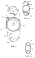
- FIGURE 1 is a top plan view of an intraocular lens and haptic anchor plate constructed in accordance with one embodiment of the invention.
- FIGURE 2 is a sectional view taken substantially along the line 2-2 of FIGURE 1.
- FIGURES 3-5 are top plan views of further embodiments.
- the intraocular lens of FIGURES 1 and 2 is designated generally as 10 which may be a single or multi-focal optical system.
- the lens includes a central disc-shaped optic portion 12 and an essentially rectangular haptic anchor plate 14 attached to the optic portion.
- the haptic anchor plate 14 has a width essentially equal to the diameter of the optic portion 12, and a length greater than the diameter of the optic portion.
- the haptic anchor plate 14 extends radially outwardly from the optic portion 12 at diametrically opposite ends of the optic portion, as shown in FIGURE 1.
- the haptic anchor plate is sufficiently rigid to prevent deformation during fibrosis, as explained above.
- the length of the haptic anchor plate corresponds to that of the capsular bag in which the lens is intended to be placed. These two factors prevent decentration of the intraocular lens when placed in the capsular bag.
- the intraocular lens 10 of FIGURE 1 includes a pair of haptic loops 16 which are staked to the extended end portions of the anchor plate 14.
- the haptic loops 16 are shorter than those usually employed in prior art intraocular lenses, this being possible because of the length of the haptic anchor plate 14.
- the haptic loops are staked to a thickened part of the haptic anchor plate 14 to one side, as shown in FIGURE 1, to facilitate folding of the intraocular lens.
- grooves are formed in the ends of the haptic anchor plate 14 which serve to receive the haptic loops 16 when the haptic loops are compressed down into the grooves.
- the haptic loops 16 are completely compressed into the grooves when the intraocular lens is placed in the capsular bag. For such a placement, the lens is held in position by the haptic anchor plate 14, and rigidity of the haptic anchor plate maintains the lens centered in the capsular bag.
- the loops 16 spring out of the grooves, and engage the sides of the sulcus so that the lens is firmly held in the sulcus, should that placement occur.
- the construction of the intraocular lens of the invention assures that there will be a predetermined orientation of the intraocular lens in the eye, and also assure that the intraocular lens will not be subject to angular or linear movement within the eye, regardless of whether the lens is properly placed in the capsular bag, or it is placed in the sulcus.
- the short haptic loops are staked to the haptic anchor plate 14 at positions such that the intraocular lens 10 may be compressed for insertion through a small incision without damage to the haptic members. Also, and as described above, decentration of the intraocular lens within the eye is minimized because the semi-rigid haptic anchor plate 14 resists folding and compression, unlike the relatively long haptic loops of the conventional intraocular lenses.
- the optic portion 12 of the intraocular lens of the invention may be formed of a soft foldable transparent plastic such as hydroxyethylmethylmethacrylate.
- the haptic anchor plate 14 may be formed of any appropriate relatively rigid material.
- the haptic loops 16 may be formed, for example, of polyamide or polypropylene (PROLENE), or other appropriate resilient material.
- the intraocular lens of FIGURE 3 is designated 100. It includes a central disc-shaped optic portion 102 and an anchor plate 104. A pair of haptic loops 106 are staked to the extended end portions of the anchor plate 104. One or both ends of each haptic loop 106 may be staked to the anchor plate 104. The haptic loops 106 and the haptic anchor plate 104 are configured, as shown, so that spaces "A" are left between the loops and the anchor plate.
- the spaces permit the anterior and posterior capsules to fuse together by fibrosis over the loops after the intraocular lens has been inserted into the bag and the loops have been compressed. This fusion firmly fixes the intraocular lens in the bag and prevents its dislocation should it become necessary to open the posterior capsule with a Y.A.G. Laser at a later date.
- FIGURE 4 shows an embodiment in which both ends of the haptic loops 16A, and 16B are anchored to the anchor plate 14. Loop 16A is notched for insertion purposes.
- FIGURE 5 shows an embodiment in which each end of the haptic anchor plate 14A is notched to receive the end of the corresponding haptic 16.
- the haptics are pushed all the way into the notches when the intraocular lens is placed in the bag, and partially into the notches when the lens is placed in the sulcus.
- the invention provides, therefore, an improved intraocular lens/anchor plate combination which enables haptic members to be attached to the lens without any reduction in the optic region, and which exhibits other distinct advantages set forth above.
Landscapes
- Health & Medical Sciences (AREA)
- Ophthalmology & Optometry (AREA)
- General Health & Medical Sciences (AREA)
- Animal Behavior & Ethology (AREA)
- Veterinary Medicine (AREA)
- Oral & Maxillofacial Surgery (AREA)
- Transplantation (AREA)
- Public Health (AREA)
- Life Sciences & Earth Sciences (AREA)
- Engineering & Computer Science (AREA)
- Chemical & Material Sciences (AREA)
- Cardiology (AREA)
- Biomedical Technology (AREA)
- Heart & Thoracic Surgery (AREA)
- Vascular Medicine (AREA)
- Epidemiology (AREA)
- Medicinal Chemistry (AREA)
- Chemical Kinetics & Catalysis (AREA)
- Dermatology (AREA)
- Prostheses (AREA)
Claims (15)
- Intraokulare Linse (10, 100) für ein Auge eines Empfänger, umfassend:einen im allgemeinen scheibenförmigen optischen Teil (12, 102);eine haptische Ankerplatte (14, 14A, 104), die sich von dem optischen Teil (12, 102) radial nach außen in entgegengesetzten Richtungen davon erstreckt;ein Paar haptischer Elemente (16, 16A, 16B, 106), die an der Ankerplatte (14, 14A, 104) an den gegenüberliegenden Seiten davon angebracht sind, wobei die haptische Ankerplatte, der optische Teil und die haptischen Elemente zueinander koplanar sind;wobei die haptische Ankerplatte eine auf die Querabmessung des Kapselsackes des Empfängerauges abgestimmte Länge hat;wobei die haptische Ankerplatte (14, 14A, 104) eine Breite hat, die im wesentlichen gleich dem Durchmesser des optischen Teils (12, 102) ist; undwobei die haptischen Elemente (16, 16A, 16B, 106) bogenförmig gekrümmte, rückstellfähige Elemente (16, 16A, 16B, 106) sind, von denen mindestens eines während des Positionierens der intraokularen Linse (10, 100) in dem Kapselsack nach unten in Richtung auf eine Kante der haptischen Ankerplatte (14, 14A, 104) zusammengedrückt werden kann und wobei mindestens eines der Elemente nach außen weg von der Ankerplatte (14, 14A, 104) für ein alternatives Positionieren der intraokularen Linse in dem Sulcus verschieblich ist, wodurch das mindestens eine Element dazu dient, die intraokulare Linse (10, 100) zentral in dem Auge des Empfängers zu positionieren.
- Intraokulare Linse (10, 100) nach Anspruch 1, bei welcher die haptischen Bügel-Elemente (16, 16A, 16B, 106) aus Polypropylen gebildet werden.
- Intraokulare Linse (10, 100) nach Anspruch 1, bei welcher mindestens eines der optischen Teile (12, 102) und die Ankerplatte (14, 14A, 104) aus Hydroxyethylmethylmethacrylat gebildet werden.
- Intraokulare Linse (10, 100) nach Anspruch 1, bei welcher mindestens eines der optischen Teile (12, 102), die Ankerplatte (14, 14A, 104) und die haptischen Elemente (16, 16A, 16B, 106) aus einem relativ harten, rückstellfähigen Kunststoffmaterial gebildet werden.
- Intraokulare Linse (10, 100) nach Anspruch 1, bei welcher die haptischen Elemente (16, 16A, 16B, 106) aus Polyimid gebildet werden.
- Intraokulare Linse (10, 100) nach Anspruch 1, bei welcher mindestens eines der optischen Teile (12, 102), die haptischen Elemente (16, 16A, 16B, 106) und die Ankerplatte (14, 14A, 104) aus Silicon gebildet werden.
- Intraokulare Linse (10, 100) nach Anspruch 1, bei welcher mindestens eines der optischen Teile (12, 102), die Ankerplatte (14, 14A, 104) und die haptischen Elemente (16, 16A, 16B, 106) aus Silicon gebildet werden.
- Intraokulare Linse (10, 100) nach einem der vorgenannten Ansprüche, bei welcher die Kanten der haptischen Ankerplatte (14, 14A, 104) an deren entsprechenden Enden darin ausgebildete Rillen aufweisen, um die bogenförmig gekrümmten haptischen Elemente (16, 16A, 16B, 106) aufzunehmen, wenn die haptischen Elemente (16, 16A, 16B, 106) nach unten in die Rillen des Kapselsackes gedrückt werden.
- Intraokulare Linse (10, 100) nach Anspruch 1, bei welcher der optische Teil (12, 102) aus Zusammenlegbarem Kunststoffmaterial gebildet wird.
- Intraokulare Linse (10, 100) nach Anspruch 1, bei welcher mindestens eines der optischen Teile (12, 102), die Ankerplatte (14, 14A, 104) und die haptischen Elemente (16, 16A, 16B, 106) aus rückstellfähigem Kunststoffmaterial gebildet werden.
- Intraokulare Linse (10, 100) nach einem der vorgenannten Ansprüche, welche Linse so konfiguriert ist, daß zwischen jedem der haptischen Elemente (16, 16A, 16B, 106) und der Ankerplatte (14, 14A, 104) ein Zwischenraum gewährt wird, wenn die intraokulare Linse (10, 100) in den Kapselsack eingesetzt ist, um zu ermöglichen, die vorderen und hinteren Kapseln des Auges durch diesen Zwischenraum mit Hilfe von Fibrose zusammenzuschweißen und die intraokulare Linse (10, 100) in dem Auge zu fixieren
- Intraokulare Linse (10, 100) nach einem der vorgenannten Ansprüche, bei welcher jedes der haptischen Elemente (16, 16A, 16B, 106) an dem einen Ende nur an der Ankerplatte (14, 14A, 104) eingesetzt ist.
- Intraokulare Linse (10, 100) nach Anspruch 1, bei welcher jedes der bogenförmig gekrümmten, rückstellfähigen haptischen Elemente (16, 16A, 16B, 106) zusammendrückbar ist und an den beiden Enden an der Ankerplatte (14, 14A, 104) angebracht ist.
- Intraokulare Linse (10, 100) nach Anspruch 12, bei welcher jedes Ende der Ankerplatte (14, 14A, 104) gekerbt ist, um das freie Ende der entsprechenden haptischen Elemente (16, 16A, 16B, 106) aufzunehmen.
- Intraokulare Linse (10, 100) nach einem der vorgenannten Ansprüche, bei welcher die intraokulare Linse (10, 100) zum Einsetzen durch einen 3 ... 4 mm-Phakoemulsifikationseinschnitt in das Auge des Empfängers zusammendrückbar ist, in den die intraokulare Linse (10, 100) eingesetzt werden soll.
Applications Claiming Priority (1)
| Application Number | Priority Date | Filing Date | Title |
|---|---|---|---|
| PCT/US1991/004001 WO1992021304A1 (en) | 1991-06-06 | 1991-06-06 | Intraocular lens with haptic anchor plate |
Publications (3)
| Publication Number | Publication Date |
|---|---|
| EP0587565A1 EP0587565A1 (de) | 1994-03-23 |
| EP0587565A4 EP0587565A4 (de) | 1995-02-22 |
| EP0587565B1 true EP0587565B1 (de) | 1998-08-19 |
Family
ID=22225583
Family Applications (1)
| Application Number | Title | Priority Date | Filing Date |
|---|---|---|---|
| EP92904476A Expired - Lifetime EP0587565B1 (de) | 1991-06-06 | 1991-06-06 | Intraokuläre linse mit einer haptischen verankerungsplatte |
Country Status (6)
| Country | Link |
|---|---|
| EP (1) | EP0587565B1 (de) |
| JP (1) | JP3233931B2 (de) |
| CA (1) | CA2110184C (de) |
| DE (1) | DE69130022T2 (de) |
| ES (1) | ES2121846T3 (de) |
| WO (1) | WO1992021304A1 (de) |
Families Citing this family (11)
| Publication number | Priority date | Publication date | Assignee | Title |
|---|---|---|---|---|
| RU2306117C2 (ru) * | 2004-07-07 | 2007-09-20 | Сергей Леонидович Кузнецов | Интраокулярная линза |
| RU2306116C2 (ru) * | 2004-07-07 | 2007-09-20 | Сергей Леонидович Кузнецов | Интраокулярная линза |
| US9295544B2 (en) | 2012-06-05 | 2016-03-29 | James Stuart Cumming | Intraocular lens |
| US8523942B2 (en) | 2011-05-17 | 2013-09-03 | James Stuart Cumming | Variable focus intraocular lens |
| US9295545B2 (en) | 2012-06-05 | 2016-03-29 | James Stuart Cumming | Intraocular lens |
| US9585745B2 (en) | 2010-06-21 | 2017-03-07 | James Stuart Cumming | Foldable intraocular lens with rigid haptics |
| US9351825B2 (en) | 2013-12-30 | 2016-05-31 | James Stuart Cumming | Semi-flexible posteriorly vaulted acrylic intraocular lens for the treatment of presbyopia |
| US10736732B2 (en) | 2010-06-21 | 2020-08-11 | James Stuart Cumming | Intraocular lens with longitudinally rigid plate haptic |
| US9918830B2 (en) | 2010-06-21 | 2018-03-20 | James Stuart Cumming | Foldable intraocular lens with rigid haptics |
| US9295546B2 (en) | 2013-09-24 | 2016-03-29 | James Stuart Cumming | Anterior capsule deflector ridge |
| US9615916B2 (en) | 2013-12-30 | 2017-04-11 | James Stuart Cumming | Intraocular lens |
Family Cites Families (11)
| Publication number | Priority date | Publication date | Assignee | Title |
|---|---|---|---|---|
| DE2556665C3 (de) * | 1975-12-16 | 1978-08-03 | Titmus Eurocon Kontaktlinsen Kg, 8750 Aschaffenburg | Intraokulare künstliche Augenlinse |
| US4056855A (en) * | 1976-04-07 | 1977-11-08 | Charles Kelman | Intraocular lens and method of implanting same |
| US4244060A (en) | 1978-12-01 | 1981-01-13 | Hoffer Kenneth J | Intraocular lens |
| US4242762A (en) * | 1979-07-25 | 1981-01-06 | Tennant Jerald L | Posterior encapsuled implant lens |
| CA1154904A (en) * | 1980-02-20 | 1983-10-11 | Howard V. Gimbel | Intraocular lens system |
| AU566263B2 (en) * | 1982-07-22 | 1987-10-15 | Mazzocco, T.R. | Fixation system for intraocular lens prosthesis |
| US4969897A (en) * | 1984-09-12 | 1990-11-13 | Kalb Irvin M | Intraocular lens with retractable leg |
| DE3439551A1 (de) * | 1984-10-29 | 1986-04-30 | Inprohold Establishment, Vaduz | Einstueckige implantationslinse |
| US4726367A (en) * | 1985-08-19 | 1988-02-23 | Shoemaker David W | Surgical instrument for implanting an intraocular lens |
| US4826832A (en) * | 1986-05-06 | 1989-05-02 | Ciba-Geigy Corporation | Penen compounds |
| US5047051A (en) * | 1990-04-27 | 1991-09-10 | Cumming J Stuart | Intraocular lens with haptic anchor plate |
-
1991
- 1991-06-06 EP EP92904476A patent/EP0587565B1/de not_active Expired - Lifetime
- 1991-06-06 DE DE69130022T patent/DE69130022T2/de not_active Expired - Fee Related
- 1991-06-06 WO PCT/US1991/004001 patent/WO1992021304A1/en not_active Ceased
- 1991-06-06 CA CA002110184A patent/CA2110184C/en not_active Expired - Fee Related
- 1991-06-06 ES ES92904476T patent/ES2121846T3/es not_active Expired - Lifetime
- 1991-06-06 JP JP50424092A patent/JP3233931B2/ja not_active Expired - Lifetime
Also Published As
| Publication number | Publication date |
|---|---|
| CA2110184A1 (en) | 1992-12-07 |
| EP0587565A4 (de) | 1995-02-22 |
| JPH06507322A (ja) | 1994-08-25 |
| WO1992021304A1 (en) | 1992-12-10 |
| JP3233931B2 (ja) | 2001-12-04 |
| DE69130022D1 (de) | 1998-09-24 |
| DE69130022T2 (de) | 1999-05-27 |
| ES2121846T3 (es) | 1998-12-16 |
| CA2110184C (en) | 2003-04-15 |
| EP0587565A1 (de) | 1994-03-23 |
Similar Documents
| Publication | Publication Date | Title |
|---|---|---|
| US5047051A (en) | Intraocular lens with haptic anchor plate | |
| AU2003218431B2 (en) | Accommodating intraocular lens with textured haptics | |
| EP0931521B1 (de) | Verbesserter endokapsularer Spannungsring | |
| US4619256A (en) | Intraocular lens inserting assembly | |
| US6322589B1 (en) | Intraocular lenses with fixated haptics | |
| US4575374A (en) | Flexible anterior chamber lens | |
| US4880427A (en) | Flexible posterior chamber lens | |
| CA1237556A (en) | Fixation system for intraocularlens structures | |
| US6660036B2 (en) | Collars for lens loops | |
| US6051024A (en) | Intraocular lenses with fixated haptics | |
| US4242762A (en) | Posterior encapsuled implant lens | |
| US5041134A (en) | Intraocular lens assembly | |
| EP0186634B1 (de) | Intraocularlinse mit umklappbaren Seitenteilen | |
| WO1998005273A1 (en) | Foldable intraocular lens | |
| US4787902A (en) | Multi-positionable intraocular lens | |
| EP1138282A1 (de) | Aufbau einer Intraokularen Linse | |
| EP0587565B1 (de) | Intraokuläre linse mit einer haptischen verankerungsplatte | |
| EP0289449A1 (de) | Hinterkammer-Linse | |
| EP0032835B1 (de) | Intraokulare Linse | |
| US4795460A (en) | Flexible three-piece posterior chamber lens | |
| EP0089335B2 (de) | Implantat für die posteriore augenkammer | |
| RU2063728C1 (ru) | Интраокулярная линза | |
| US4562599A (en) | Intraocular lens |
Legal Events
| Date | Code | Title | Description |
|---|---|---|---|
| PUAI | Public reference made under article 153(3) epc to a published international application that has entered the european phase |
Free format text: ORIGINAL CODE: 0009012 |
|
| 17P | Request for examination filed |
Effective date: 19940103 |
|
| AK | Designated contracting states |
Kind code of ref document: A1 Designated state(s): DE ES FR GB IT |
|
| A4 | Supplementary search report drawn up and despatched | ||
| AK | Designated contracting states |
Kind code of ref document: A4 Designated state(s): DE ES FR GB IT |
|
| 17Q | First examination report despatched |
Effective date: 19960624 |
|
| GRAG | Despatch of communication of intention to grant |
Free format text: ORIGINAL CODE: EPIDOS AGRA |
|
| GRAG | Despatch of communication of intention to grant |
Free format text: ORIGINAL CODE: EPIDOS AGRA |
|
| RIN1 | Information on inventor provided before grant (corrected) |
Inventor name: CUMMING, J. STUART |
|
| RAP1 | Party data changed (applicant data changed or rights of an application transferred) |
Owner name: MEDEVEC LICENSING B.V. |
|
| GRAG | Despatch of communication of intention to grant |
Free format text: ORIGINAL CODE: EPIDOS AGRA |
|
| GRAH | Despatch of communication of intention to grant a patent |
Free format text: ORIGINAL CODE: EPIDOS IGRA |
|
| GRAH | Despatch of communication of intention to grant a patent |
Free format text: ORIGINAL CODE: EPIDOS IGRA |
|
| GRAG | Despatch of communication of intention to grant |
Free format text: ORIGINAL CODE: EPIDOS AGRA |
|
| GRAA | (expected) grant |
Free format text: ORIGINAL CODE: 0009210 |
|
| AK | Designated contracting states |
Kind code of ref document: B1 Designated state(s): DE ES FR GB IT |
|
| REF | Corresponds to: |
Ref document number: 69130022 Country of ref document: DE Date of ref document: 19980924 |
|
| REG | Reference to a national code |
Ref country code: ES Ref legal event code: FG2A Ref document number: 2121846 Country of ref document: ES Kind code of ref document: T3 |
|
| ET | Fr: translation filed | ||
| PLBE | No opposition filed within time limit |
Free format text: ORIGINAL CODE: 0009261 |
|
| STAA | Information on the status of an ep patent application or granted ep patent |
Free format text: STATUS: NO OPPOSITION FILED WITHIN TIME LIMIT |
|
| 26N | No opposition filed | ||
| PGFP | Annual fee paid to national office [announced via postgrant information from national office to epo] |
Ref country code: GB Payment date: 20000531 Year of fee payment: 10 |
|
| PGFP | Annual fee paid to national office [announced via postgrant information from national office to epo] |
Ref country code: FR Payment date: 20000624 Year of fee payment: 10 |
|
| PGFP | Annual fee paid to national office [announced via postgrant information from national office to epo] |
Ref country code: DE Payment date: 20000704 Year of fee payment: 10 |
|
| PGFP | Annual fee paid to national office [announced via postgrant information from national office to epo] |
Ref country code: ES Payment date: 20000714 Year of fee payment: 10 |
|
| PG25 | Lapsed in a contracting state [announced via postgrant information from national office to epo] |
Ref country code: GB Free format text: LAPSE BECAUSE OF NON-PAYMENT OF DUE FEES Effective date: 20010606 |
|
| PG25 | Lapsed in a contracting state [announced via postgrant information from national office to epo] |
Ref country code: ES Free format text: LAPSE BECAUSE OF NON-PAYMENT OF DUE FEES Effective date: 20010607 |
|
| GBPC | Gb: european patent ceased through non-payment of renewal fee |
Effective date: 20010606 |
|
| PG25 | Lapsed in a contracting state [announced via postgrant information from national office to epo] |
Ref country code: FR Free format text: LAPSE BECAUSE OF NON-PAYMENT OF DUE FEES Effective date: 20020228 |
|
| PG25 | Lapsed in a contracting state [announced via postgrant information from national office to epo] |
Ref country code: DE Free format text: LAPSE BECAUSE OF NON-PAYMENT OF DUE FEES Effective date: 20020403 |
|
| REG | Reference to a national code |
Ref country code: ES Ref legal event code: FD2A Effective date: 20030303 |
|
| PGFP | Annual fee paid to national office [announced via postgrant information from national office to epo] |
Ref country code: IT Payment date: 20060630 Year of fee payment: 16 |
|
| PG25 | Lapsed in a contracting state [announced via postgrant information from national office to epo] |
Ref country code: IT Free format text: LAPSE BECAUSE OF NON-PAYMENT OF DUE FEES Effective date: 20070606 |