EP0586084A2 - Reproducing apparatus - Google Patents
Reproducing apparatus Download PDFInfo
- Publication number
- EP0586084A2 EP0586084A2 EP93305957A EP93305957A EP0586084A2 EP 0586084 A2 EP0586084 A2 EP 0586084A2 EP 93305957 A EP93305957 A EP 93305957A EP 93305957 A EP93305957 A EP 93305957A EP 0586084 A2 EP0586084 A2 EP 0586084A2
- Authority
- EP
- European Patent Office
- Prior art keywords
- bias voltage
- optical disc
- disc
- area
- switching
- Prior art date
- Legal status (The legal status is an assumption and is not a legal conclusion. Google has not performed a legal analysis and makes no representation as to the accuracy of the status listed.)
- Granted
Links
Images


Classifications
-
- G—PHYSICS
- G11—INFORMATION STORAGE
- G11B—INFORMATION STORAGE BASED ON RELATIVE MOVEMENT BETWEEN RECORD CARRIER AND TRANSDUCER
- G11B7/00—Recording or reproducing by optical means, e.g. recording using a thermal beam of optical radiation by modifying optical properties or the physical structure, reproducing using an optical beam at lower power by sensing optical properties; Record carriers therefor
- G11B7/08—Disposition or mounting of heads or light sources relatively to record carriers
- G11B7/09—Disposition or mounting of heads or light sources relatively to record carriers with provision for moving the light beam or focus plane for the purpose of maintaining alignment of the light beam relative to the record carrier during transducing operation, e.g. to compensate for surface irregularities of the latter or for track following
- G11B7/094—Methods and circuits for servo offset compensation
-
- G—PHYSICS
- G11—INFORMATION STORAGE
- G11B—INFORMATION STORAGE BASED ON RELATIVE MOVEMENT BETWEEN RECORD CARRIER AND TRANSDUCER
- G11B11/00—Recording on or reproducing from the same record carrier wherein for these two operations the methods are covered by different main groups of groups G11B3/00 - G11B7/00 or by different subgroups of group G11B9/00; Record carriers therefor
- G11B11/10—Recording on or reproducing from the same record carrier wherein for these two operations the methods are covered by different main groups of groups G11B3/00 - G11B7/00 or by different subgroups of group G11B9/00; Record carriers therefor using recording by magnetic means or other means for magnetisation or demagnetisation of a record carrier, e.g. light induced spin magnetisation; Demagnetisation by thermal or stress means in the presence or not of an orienting magnetic field
- G11B11/105—Recording on or reproducing from the same record carrier wherein for these two operations the methods are covered by different main groups of groups G11B3/00 - G11B7/00 or by different subgroups of group G11B9/00; Record carriers therefor using recording by magnetic means or other means for magnetisation or demagnetisation of a record carrier, e.g. light induced spin magnetisation; Demagnetisation by thermal or stress means in the presence or not of an orienting magnetic field using a beam of light or a magnetic field for recording by change of magnetisation and a beam of light for reproducing, i.e. magneto-optical, e.g. light-induced thermomagnetic recording, spin magnetisation recording, Kerr or Faraday effect reproducing
- G11B11/10595—Control of operating function
- G11B11/10597—Adaptations for transducing various formats on the same or different carriers
-
- G—PHYSICS
- G11—INFORMATION STORAGE
- G11B—INFORMATION STORAGE BASED ON RELATIVE MOVEMENT BETWEEN RECORD CARRIER AND TRANSDUCER
- G11B13/00—Recording simultaneously or selectively by methods covered by different main groups among G11B3/00, G11B5/00, G11B7/00 and G11B9/00; Record carriers therefor not otherwise provided for; Reproducing therefrom not otherwise provided for
- G11B13/04—Recording simultaneously or selectively by methods covered by different main groups among G11B3/00, G11B5/00, G11B7/00 and G11B9/00; Record carriers therefor not otherwise provided for; Reproducing therefrom not otherwise provided for magnetically or by magnetisation and optically or by radiation, for changing or sensing optical properties
-
- G—PHYSICS
- G11—INFORMATION STORAGE
- G11B—INFORMATION STORAGE BASED ON RELATIVE MOVEMENT BETWEEN RECORD CARRIER AND TRANSDUCER
- G11B19/00—Driving, starting, stopping record carriers not specifically of filamentary or web form, or of supports therefor; Control thereof; Control of operating function ; Driving both disc and head
- G11B19/02—Control of operating function, e.g. switching from recording to reproducing
- G11B19/12—Control of operating function, e.g. switching from recording to reproducing by sensing distinguishing features of or on records, e.g. diameter end mark
-
- G—PHYSICS
- G11—INFORMATION STORAGE
- G11B—INFORMATION STORAGE BASED ON RELATIVE MOVEMENT BETWEEN RECORD CARRIER AND TRANSDUCER
- G11B7/00—Recording or reproducing by optical means, e.g. recording using a thermal beam of optical radiation by modifying optical properties or the physical structure, reproducing using an optical beam at lower power by sensing optical properties; Record carriers therefor
- G11B7/08—Disposition or mounting of heads or light sources relatively to record carriers
- G11B7/09—Disposition or mounting of heads or light sources relatively to record carriers with provision for moving the light beam or focus plane for the purpose of maintaining alignment of the light beam relative to the record carrier during transducing operation, e.g. to compensate for surface irregularities of the latter or for track following
- G11B7/0945—Methods for initialising servos, start-up sequences
Definitions
- an object of this invention is to provide a focus bias switching circuit which adjusts to the optimum focus position for each recording medium.
- the optimum focus position can be obtained for each area, and the recorded data can be reproduced with a reduced bit error rate.
- the bias voltage VT is switched between the magneto-optical disc 2B and the composite disc 2C so that the optimum position can be obtained respectively for the composite disc 2C and magneto-optical disc 2B. This makes it possible to play-back the recording data with a reduced bit error rate.
- the focus control operation is started in this center position so as to focus-control certainly.
Landscapes
- Optical Recording Or Reproduction (AREA)
Abstract
Description
- The present invention relates to a reproducing apparatus such as, for example, an apparatus for recording and reproducing music data by using such as a magneto-optical disc, and an optical disc apparatus having a reproducible optical disc having pits, such as compact disc, etc..
- In an optical disc apparatus such as a compact disc player and so on, an apparatus is disclosed in U.S. Patent No. 4,512,003 in which the reflected light obtained from the compact disc is received and a focus error signal is generated to focus-control on the basis of this focus error signal.
- Specifically, as shown in Fig. 1, in an
optical disc apparatus 1, anoptical disc 2 is-rotated by aspindle motor 4, and a light beam emitted from the optical apparatus of an optical pick-up 6 radiates to theoptical disc 2 in this state. - Further, in the
optical disc apparatus 1, the reflected light from theoptical disc 2 is received by the optical system and its output signal is outputted to a focuserror detecting circuit 8. - As shown in Fig. 2, in the optical disc apparatus such as a compact disc player, the reflected light from the optical disc is received by a
photo detector 10 via a cylindrical lens, wherein the defocusing amount of the light beam is detected by using a so-called astigmatism method. - To be specific, in the
photo detector 10, a light receiving plane is divided into two toward the radial direction of theoptical disc 2, and moreover, is divided into two toward the direction orthogonalizing with the radial direction of theoptical disc 2. The focuserror detecting circuit 8 Current-Voltage transforms the output current of each light receiving plane by a current-voltage transform circuit 12, and then, outputs it to adifferential amplifier circuit 14. - Here, the
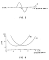
differential amplifier circuit 14 adds the output signals of the light receiving planes positioning toward the direction of a diagonal line, thereafter, a differential signal is generated between the respective added signals. Therefore, as shown in Fig. 3, a focus error signal FE such that the signal level changes in a "S" shape in accordance with the defocusing quantity is generated. - In the state that the focus servo loop is not closed, a
system control circuit 48 controls aswitching circuit 68 by a control signal S1 to switch to B side, and thereafter a SSP (signal servo control processor) 66 generates a focus search voltage signal S2 in order to move an object lens up and down for the disc. Then, the focus search voltage signal S2 moves the object lens up and down via adrive circuit 26 and afocus lens actuator 28. When the object lens comes up to thedisc 2, a "S" shape signal is obtained as shown in Fig. 3, and theSSP 66 controls theselecting circuit 68 in order to switch from B side to A side when the coincident point near "0" which is the center of the "S" shape in Fig. 3 is detected. With this control, the focus servo is closed. - In the state that the focus servo is closed, the focus
error detecting circuit 8 inputs this focus error signal FE to anoperational amplifier circuit 22 composed of an inverting amplifier circuit, which has aninput resistor 16, agrounding resistor 18 and a feed-back resistor 20, and outputs the output signal of theoperational amplifier circuit 22 to aphase compensating circuit 24. - The
phase compensating circuit 24 compensates the phase of the focus error signal FE and outputs it, and thedrive circuit 26 drives afocus lens actuator 28 in accordance with the output signal of theoperational amplifier circuit 22. - Hence, the focus
error detecting circuit 8 moves the object lens up and down in order that the signal level of the focus error signal FE becomes "0" level, so that the defocusing quantity is kept to "0". - Because the dispersion or the astigmatism can not prevent in the optical system or the like, in this type of the optical pick-up, a predetermined bias voltage is added on the focus error signal FE and this bias voltage is adjusted so as to focus-adjust.
- That is, the focus
error detecting circuit 8 connects a variable resistor 30 between a positive power source +B and a negative power source -B, and inputs the bias voltage VB formed by this variable resistor 30 to theoperational amplifier circuit 22. - In this way, in the
optical disc apparatus 1, the dispersion, etc. of the optical system can be corrected by adjusting this variable resistor 30. - However, in this type of optical disc apparatus, a system which enables not only the playing-back of a compact disc having pits and lands but also the recording and playing-back of information by using an magneto-optical disc having wobbling grooves and lands cut previously, has been provided.
- In this optical disc apparatus, when the value of the bias voltage VB is changed slowly and the jitter is detected, as shown in Fig. 4, it is recognized that the focus position having the smallest jitter is not coincided between a characteristics of the compact disc (represented by the character "CD") and the magneto-optical disc (represented by the character "MO").
- In the conventional optical disc, the bias voltage is fixed and is not changed in accordance with the recording medium. For example, in Fig. 4, the bias voltage VB is adjusted to the range in which the characteristics of the jitter of MO and CD is allowable (the defocusing quantity is near "0").
- However, since the bias voltage is differed slightly from the optimum value of the jitter in each disc, in the case where flaws or fingerprints are stuck on the disc, there is a problem that the sound may jump easily.
- Furthermore, because the bit error rate changes accompanying the change of jitter, in this type of optical disc system, if it can be adjusted to the optimum focus position for each recording medium, the bit error ratio can be improved by this adjustment.
- In view of the foregoing, an object of this invention is to provide a focus bias switching circuit which adjusts to the optimum focus position for each recording medium.
- First and second aspects of the invention are set out in appended
claims - In one embodiment of the invention, there is provided an optical disc apparatus in which an
optical disc 2A and a magneto-optical disc 2B are kept to be exchangeable, and a light beam emitted from an optical pick-up is focused to theoptical disc 2A or the magneto-optical disc 2B to reproduce the recorded data of theoptical disc 2A or the magneto-optical disc 2B. Theoptical disc apparatus 40 comprises means for generatingfocus error signal optical disc 2A and the magneto-optical disc 2B and for generating a focus error signal FE, a means for correctingfocus error signal 16 through 22, 32 and 42 through 52 for adding a bias voltage VB on the focus error signal FE and for correcting the signal level of the focus error signal FE, and focus driving means 24, 26 and 28 for adjusting the focus position of the light beam based on the focus error signal FE corrected by the means for correctingfocus error signal 16 through 22, 32 and 42 through 52. The disc judgement means 70 judges whether the set disc is theoptical disc 2A or the magneto-optical disc 2B, and then the means for correctingfocus error signal 16 through 22, 32 and 42 through 52 switches the bias voltage VB accordingly. - Further, in an embodiment of the invention, there is provided an
optical disc apparatus 40 in which the light beam emitted from the optical pick-up is focused to the disc to reproduce the recorded data of theoptical disc 2A, and moreover the data is recorded in the magneto-optical disc 2B and the recorded data is produced. Theoptical disc apparatus 40 comprises the means for generatingfocus error signal focus error signal 16 through 22, 32 and 42 through 52 for adding the bias voltage VB on the focus error signal FE and for correcting the signal level of the focus error signal FE, and a focus driving means 24, 26 and 28 for adjusting the focus position of the light beam based on the focus error signal FE corrected by the means for correctingfocus error signal 16 through 22, 32 and 42 through 52. In the case that a composite disc 2C, having the inner periphery area in which the predetermined data is previously recorded by forming pits and the outer periphery area in which the magneto recording area is formed and the desired data can be thermomagnetically recorded, is set at theoptical disc apparatus 1, the disc judgement means 70 judges the disc, and the means for correctingfocus error signal 16 through 22, 32 and 42 through 52 switches the bias voltage VB in accordance with the area of inner periphery side and outer periphery side. - The means for correcting
focus error signal 16 through 22, 32 and 42 through 52 can add the bias voltage VB on the focus error signal FE via a predetermined timeconstant circuit - By switching the bias voltage VB correcting the area of signal level of the focus error signal FE between the
optical disc 2A and the magneto-optical disc 2B, the optimum focus position can be adjusted for theoptical disc 2 and the magneto-optical disc. - Further, by switching the bias voltage VB between the area of the inner periphery side and the area of the outer periphery side, it is adjusted to the optimum focus position for the respective areas of the inner and outer periphery sides.
- At this time, the bias voltage VB is added on the focus error signal FE via the predetermined time
constant circuits - In an embodiment of the invention, the bias voltage is switched between the optical disc and the magneto-optical disc, and the signal level of the focus error signal is corrected, so that the optical disc system, which can adjust to the optimum focus position for each recording medium, can be obtained.
- The nature, principle and utility of the invention will become more apparent from the following detailed description when read in conjunction with the accompanying drawings in which like parts are designated by like reference numerals or characters.
- Exemplary embodiments of the invention will be described hereinafter, by way of examples only, with reference to the accompanying drawings, in which:
- Fig. 1 is a block diagram showing a conventional construction;
- Fig. 2 is a block diagram showing a conventional optical disc apparatus;
- Fig. 3 is a signal waveform chart showing the focus error signal thereof;
- Fig. 4 is a characteristic curve diagram representing the relation ship between the focus error signal and the jitter;
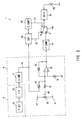
- Fig. 5 is a block diagram showing an optical disc apparatus according to first and embodiment of the present invention;
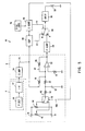
- Fig. 6 is a block diagram showing the optical disc apparatus according to second embodiment of the present invention;
- Figs. 7A to 7E are signal waveform charts for the explanation of the operation thereof;
- Fig. 8 is a sectional view of the optical disc having a programming area of pits;
- Fig. 9 is a sectional view of the magneto-optical disc having a programming area of grooves; and
- Fig. 10 is a sectional view of the composite disc having a first area with a programming area of pits and a second area with a programming area of grooves.
- Preferred embodiments of the present invention will be described with reference to the accompanying drawings:
- Referring to Fig. 5 wherein the portions corresponding to those of Fig. 1 are designated with the same reference numerals or characters, 40 denotes an entire optical disc apparatus, wherein the bias voltage VB is switched in accordance with the type of
disc 2. - In the
optical disc apparatus 40, theoptical disc 2A or the magneto-optical disc 2B can be set to be exchangeable. Theoptical disc apparatus 40 can reproduce theoptical disc 2A having pits, while the desired information can be recorded and reproduced by using the magneto-optical disc in which the weaving grooves are cut previously. A sectional view of theoptical disc 2A is shown in Fig. 8. - A laser light is irradiated from the optical pickup to the recording medium surface of the magneto-
optical disc 2B (Fig. 9) with the increased laser power. When the temperature exceeds the Curie temperature (approximately, 180 degrees Centigrade), the polarity magnetized in the recording medium is lost, and if the magnetic field is made at the moment when the temperature drops from the Curie temperature, the recording medium is magnetized. - The reproducing method of the magneto-
optical disc 2B uses the characteristic (which is generally called as "Kerr effect") that when the weak laser light is irradiated to a MO film, the deflection angle of the reflected light changes in response to the polarity of whether N-pole or S-pole. The reflected light is passed through an analyzer so that the polarity of the deflection angle is converted into the intensity of the light to reproduce. - The magneto-
optical disc 2B have a first area with pits for producing only in the innermost periphery side and a second area with wobbling grooves for recording in the outer area from the innermost periphery side. The sectional view of the magneto-optical disc 2B is shown in Fig. 9. The information of, for instance, the type of disc have been recorded in the first area of the magneto-optical disc 2B, and therefore the data is recorded in the second area based on the information of first area. Theoptical disc apparatus 40 switches the bias voltage VB in order to correspond to these two types of disc. - Specifically, in the
optical disc apparatus 40, as shown in Fig. 5, twovariable resistors variable resistors - Further, in the
optical disc apparatus 40, the first and second bias voltages is outputted to aselection circuit 46, and the disc judgement means 70 judges the set disc whether theoptical disc 2A or the magneto-optical disc 2B. Then, asystem control circuit 48 outputs the switching signal FBC on the basis of the judged result, so that the first and second bias voltages are selected and outputted. It is conceived that the refractive index of the surface of disc or the data (in this case, the identification code is recorded previously on the disc) recorded on the disc, and an identification holes spotted on a cartridge can be used as the judgement means 70 in the case where the disc set in a cartridge can be used as the judgement means 70. - To be specific, in the
optical disc apparatus 40, by switching the contact point between the optical disc and the magneto-optical disc 2B, the bias voltage VB to be outputted to aoperational amplifier circuit 22 is switched in accordance with the type of disc. - Therefore, in the
optical disc system 40, thevariable resistors optical disc 2A and the magneto-optical disc 2B of which the optical characteristic is supposed to be standard so as to adjust the focus position to the optimum position respectively for theoptical disc 2A and magneto-optical disc 2B. Thus, the recorded data is reproduced with a reduced bit error rate. - In addition to the
optical disc 2A of which programming area is composed of pits and the magneto-optical disc 2B of which the programming area is composed of wobbling grooves, the composite disc, composed of the first programming area with pits on one disc for reproducing operation only, and the second programming area with wobbling grooves for both of record and reproducing operation, is provided. The sectional view of the composite disc 2C is shown in Fig. 10. In the case of the composite disc, theoptical disc apparatus 40 switches the contact point of theselection circuit 46 between the first area and the second area. This enables to switch the bias voltage outputted to theoperational amplifier circuit 22 for each area. - In this manner, in the
optical disc system 40, the optimum focus position can be obtained for each area, and the recorded data can be reproduced with a reduced bit error rate. - Further, the magneto-
optical disc 2B has the pit area and groove area, and the difference between the magneto-optical disc 2B and the composite disc 2C is only one point in which the pit area is used for only a read-in area in the magneto-optical disc 2B and is used for the read-in area and the programming area in the composite disc 2C. In the first embodiment, the bias is not switched between the read-in area with pits and a recordable area with grooves in the magneto-optical disc 2B, but the bias may be switched such like the composite disc 2C. - Further, in this embodiment, the
optical disc apparatus 40 outputs the output signal of theselection circuit 62 to theoperational amplifier circuit 22 via the time constant circuit consisting of theresistors capacitor 52. This enables the voltage inputted to theoperational amplifier circuit 22 to change slowly. - Specifically, as shown in Fig. 7A to 7E, when the time constant circuit is omitted, the bias voltage VB changes suddenly (Fig. 7A) following the switching of contact point of the selecting
circuit 62. In this case, in theoptical disc apparatus 60, the signal level of the focus error signal FE changes suddenly (Fig. 7B). - That is, in this type of
optical disc apparatus 60, if the bias voltage is switched suddenly, it may enter a defocusing state. In this case, it can not be focus-controlled correctly unless it is focus-searched again. - Therefore, if the defocusing occurs frequently when the composite disc 2C is recorded and played-back, in the
optical disc system 40, it is necessary to focus-search every time when the area is switched between the inner and outer periphery side, and there is a demerit that the access time lengthen. - In the
optical disc system 60 of this embodiment, however, the output signal of theselection circuit 62 is outputted to theoperational amplifier circuit 22 via the time constant circuit so that the sudden change of the bias voltage VB can be prevented previously (Fig. 7C), and the input voltage VT of theoperational amplifier circuit 22 can rise slowly (Fig. 7D). - In this manner, in the
optical disc system 60, the sudden change of the focus error can be prevented previously (Fig. 7E) and the defocusing can be prevented previously. - With the above constitution, the bias voltage VT is switched between the magneto-
optical disc 2B and the composite disc 2C so that the optimum position can be obtained respectively for the composite disc 2C and magneto-optical disc 2B. This makes it possible to play-back the recording data with a reduced bit error rate. - In Fig. 6, 60 shows the optical disc system according to the second invention, wherein the bias voltage VB is switched by the
selection circuit 62, and at the same time, theresistor 64 is selected and the output voltage of theselection circuit 62 is kept to "0" level. - Specifically, in this type of optical disc apparatus, when the
optical disc 2A is exchanged, after the object glass is moved near the optical disc, the object glass goes farther from theoptical disc 2 gradually while the focus error signal FE is monitored. This enables it to detect the position of "0" level which is the center of the "S" letter characteristic of the focus error signal FE. - Therefore, in the
optical disc apparatus 60, the focus control operation is started in this center position so as to focus-control certainly. - However, in this focus searching, if the focus error signal FE is biased with a high bias voltage, there is a case that the correct center position can not be detected.
- For this reason, the
optical disc system 60, during focus-searching, switches the contact point to theresistor 64 and drops the bias voltage VB to "0" level. - The
system control circuit 48 outputs the driving signal of the focus searching, etc., and the servo-control processor (SSP) 66, during focus-searching, drives thedrive circuit 26 and moves the position of the object lens sequentially, and at this time, monitors the focus error signal FE and performs the focus searching process. Here, the servo-control processor (SSP) 66 outputs the control signal switching theselection circuit 68 from B side to A side, when the position of "0" level which is the center of "S" letter shape of the focus error signal FE, and at the same time, switches the contact point of theselection circuit 62 to theadjustable resistors - Note that the embodiments discussed above have dealt with the case where the focus signal is generated by using a so-called astigmatism method. However, the present invention is not limited to this, but it may be widely applied to the case where the focus error signal is generated by using various methods for generating focus error signal.
- Further, the embodiments discussed above have dealt with the case where the desired information is recorded and played-back using a compact disc or a magneto-optical disc. However, the present invention is not limited to this but it can be used widely for the optical disc apparatus which uses a various disc type recording medium.
- Furthermore, the embodiments discussed above have dealt with the case where the composite disc have the first and second area. However, the present invention is not limited to this but it can used to the disc having a plurality of areas.
- Furthermore, the arrangement of the pit area and the groove area is not limited in the present invention.
- While there has been described in connection with the preferred embodiments of the invention, it will be obvious to those skilled in the art that various changes and modifications may be aimed, therefore, to cover in the appended claims all such changes and modifications as fall within the scope of the invention.
Claims (10)
- A reproduction apparatus comprising:
a light receiving means for receiving the reflected light of a light beam irradiated from an optical pick-up to a disc;
a generation means for generating a focus error signal by using the signal supplied from said light receiving means;
a bias voltage generation means for generating first bias voltage;
a bias voltage generation means for generating second bias voltage;
a switching means for switching said first and second bias voltage generation means selectively;
a control means for controlling by switching selectively said switching means in accordance with the type of disc;
an adding means for adding the bias voltage from said selected first or second bias means to said focus error signal; and
a driving means for driving an object lens of said optical pick-up based on the signal outputted from said adding means. - The reproduction apparatus of claim 1, wherein:
said control means comprises a judgement means for judging whether the optical disc with pits and lands is set or the magneto-optical disc with grooves and lands carved previously, and controls by switching said switching means based on said judgement means. - The reproduction apparatus of claim 1, wherein:
said control means, in the disc having a first area with pits and lands and a second area with grooves and lands carved previously, controls by switching the switching means when the process moves, from the first area to the second area or from the second area to the first area. - The reproduction apparatus of claim 1, wherein:
the time constant circuit is equipped between said switching means and said adding means. - The reproduction apparatus of claim 1, wherein:
said first and second bias voltage generation means has the variable resistors. - A reproduction apparatus comprising:
a light receiving means for receiving the reflected light of a light beam irradiated from an optical pick-up to a disc;
a generation means for generating a focus error signal by using the signal supplied from said light receiving means;
a bias voltage generation means for generating first bias voltage;
a bias voltage generation means for generating second bias voltage;
a bias voltage generation means for generating third bias voltage;
a switching means for switching said first, second and third bias voltage generation means selectively;
a control means for controlling by switching selectively the switching means to the first bias voltage generation means before the focus servo closes, and to the second and third bias voltage generation means after the focus servo closes;
an adding means for adding the bias voltage from said selected first or second bias means to said focus error signal; and
a driving means for driving an object lens of said optical pick-up based on the signal outputted from said adding means. - The reproduction apparatus of claim 6, wherein:
said control means comprises a judgement means for judging whether the optical disc having pits and lands is set or the magneto-optical disc having grooves and lands carved previously, and controls by switching said switching means based on said judgement means. - The reproduction apparatus of claim 6, wherein:
said control means, in the disc having a first area with pits and lands and a second area with grooves and lands carved previously, controls by switching the switching means when the process moves, from the first area to the second area or from the second area to the first area. - The reproduction apparatus of claim 6, wherein:
the time constant circuit is equipped between said switching means and said adding means. - The reproduction apparatus of claim 6, wherein:
said first voltage generation means has the fixed resistors and said second and third bias voltage generation means has the variable resistors.
Priority Applications (1)
| Application Number | Priority Date | Filing Date | Title |
|---|---|---|---|
| EP97200384A EP0782133B1 (en) | 1992-08-04 | 1993-07-28 | Reproducing apparatus |
Applications Claiming Priority (2)
| Application Number | Priority Date | Filing Date | Title |
|---|---|---|---|
| JP22800692 | 1992-08-04 | ||
| JP228006/92 | 1992-08-04 |
Related Child Applications (1)
| Application Number | Title | Priority Date | Filing Date |
|---|---|---|---|
| EP97200384A Division EP0782133B1 (en) | 1992-08-04 | 1993-07-28 | Reproducing apparatus |
Publications (3)
| Publication Number | Publication Date |
|---|---|
| EP0586084A2 true EP0586084A2 (en) | 1994-03-09 |
| EP0586084A3 EP0586084A3 (en) | 1994-08-03 |
| EP0586084B1 EP0586084B1 (en) | 1998-04-08 |
Family
ID=16869705
Family Applications (2)
| Application Number | Title | Priority Date | Filing Date |
|---|---|---|---|
| EP93305957A Expired - Lifetime EP0586084B1 (en) | 1992-08-04 | 1993-07-28 | Reproducing apparatus |
| EP97200384A Expired - Lifetime EP0782133B1 (en) | 1992-08-04 | 1993-07-28 | Reproducing apparatus |
Family Applications After (1)
| Application Number | Title | Priority Date | Filing Date |
|---|---|---|---|
| EP97200384A Expired - Lifetime EP0782133B1 (en) | 1992-08-04 | 1993-07-28 | Reproducing apparatus |
Country Status (4)
| Country | Link |
|---|---|
| US (1) | US5463602A (en) |
| EP (2) | EP0586084B1 (en) |
| KR (1) | KR100275061B1 (en) |
| DE (2) | DE69317831T2 (en) |
Cited By (5)
| Publication number | Priority date | Publication date | Assignee | Title |
|---|---|---|---|---|
| EP0777218A1 (en) * | 1995-12-06 | 1997-06-04 | Discovision Associates | Apparatus and method for focus control |
| WO1999017283A1 (en) * | 1997-09-26 | 1999-04-08 | Daewoo Electronics Co., Ltd. | Method and apparatus for automatically adjusting a focus bias voltage |
| EP1065661A2 (en) * | 1999-06-30 | 2001-01-03 | Pioneer Corporation | Apparatus and method for automatically adjusting bias voltage of focus error signal |
| EP1091356A2 (en) * | 1999-10-07 | 2001-04-11 | Pioneer Corporation | Bias voltage controlling apparatus, information reproducing apparatus and information recording apparatus |
| EP1341163A3 (en) * | 2002-02-28 | 2004-05-06 | Fujitsu Limited | Optical recording device, and method of determining optimum focus offset value for the device |
Families Citing this family (15)
| Publication number | Priority date | Publication date | Assignee | Title |
|---|---|---|---|---|
| US6236625B1 (en) | 1991-02-15 | 2001-05-22 | Discovision Associates | Optical disc system having current monitoring circuit with controller for laser driver and method for operating same |
| US5677899A (en) | 1991-02-15 | 1997-10-14 | Discovision Associates | Method for moving carriage assembly from initial position to target position relative to storage medium |
| US5729511A (en) | 1991-02-15 | 1998-03-17 | Discovision Associates | Optical disc system having servo motor and servo error detection assembly operated relative to monitored quad sum signal |
| KR0133982B1 (en) * | 1994-04-13 | 1998-04-22 | 김광호 | Initial position setting method for pick-up unit |
| US6434087B1 (en) | 1995-01-25 | 2002-08-13 | Discovision Associates | Optical disc system and method for controlling bias coil and light source to process information on a storage medium |
| US6034936A (en) | 1995-01-31 | 2000-03-07 | Sony Corporation | Optical recording medium reproducing apparatus for reproducing low density and high density recording media |
| US5978329A (en) | 1995-06-07 | 1999-11-02 | Discovision Associates | Technique for closed loop servo operation in optical disc tracking control |
| JP3465413B2 (en) * | 1995-06-16 | 2003-11-10 | ソニー株式会社 | Optical disk drive and focus control method |
| JP3525572B2 (en) * | 1995-09-12 | 2004-05-10 | 松下電器産業株式会社 | Automatic medium exchange device and recording / reproducing device |
| US5892743A (en) * | 1996-04-02 | 1999-04-06 | Matsushita Electric Industrial Co., Ltd. | Information reproducing method and apparatus with servo characteristic change for sound reproduction |
| TW385435B (en) * | 1996-05-30 | 2000-03-21 | Hitachi Ltd | An optical disk discriminating system of optical disk apparatus |
| US20050058039A1 (en) * | 1997-01-16 | 2005-03-17 | Yasuo Kamatani | Multi-standard optical disk and method and apparatus of reading from and recording to the disk |
| US5959280A (en) * | 1997-01-16 | 1999-09-28 | Laser Dynamics, Inc. | Multi-standard optical disk reading apparatus and method of reading using same |
| MY118961A (en) * | 1998-09-03 | 2005-02-28 | Sony Corp | Beam irradiation apparatus, optical apparatus having beam irradiation apparatus for information recording medium, method for manufacturing original disk for information recording medium, and method for manufacturing information recording medium |
| KR20080021157A (en) * | 2005-06-30 | 2008-03-06 | 코닌클리케 필립스 일렉트로닉스 엔.브이. | A method for gradually closing down a focus control loop of an optical drive system |
Citations (2)
| Publication number | Priority date | Publication date | Assignee | Title |
|---|---|---|---|---|
| DE3612829A1 (en) * | 1985-04-16 | 1986-10-16 | Olympus Optical Co., Ltd., Tokio/Tokyo | OPTICAL INFORMATION RECORDING / PLAYBACK DEVICE |
| EP0423731A2 (en) * | 1989-10-16 | 1991-04-24 | Matsushita Electric Industrial Co., Ltd. | Track access device and tracking control device |
Family Cites Families (10)
| Publication number | Priority date | Publication date | Assignee | Title |
|---|---|---|---|---|
| JPS5755548A (en) * | 1980-09-19 | 1982-04-02 | Fujitsu Ltd | Magnetic disk device |
| JPS58121137A (en) * | 1982-01-09 | 1983-07-19 | Sony Corp | Focus drawing-in circuit of optical disk reproducer |
| US5289451A (en) * | 1984-11-29 | 1994-02-22 | Canon Kabushiki Kaisha | Optical information recording/reproduction apparatus including means for detecting the type of recording medium |
| JPS61188745A (en) * | 1985-02-15 | 1986-08-22 | Olympus Optical Co Ltd | Focus-servocontrol system |
| CA1261467A (en) * | 1985-11-28 | 1989-09-26 | Akira Minami | Focus servomechanism control system of optical disc system having offset setting means |
| US5173886A (en) * | 1986-02-07 | 1992-12-22 | Matsushita Electric Industrial Co., Ltd. | Composite optical disc having both a data read-only area and a data rewritable area, and a recording/reproducing system for use therewith |
| JPS63109366U (en) * | 1986-12-27 | 1988-07-14 | ||
| JPH02294938A (en) * | 1989-05-09 | 1990-12-05 | Olympus Optical Co Ltd | Optical information recording and reproducing device |
| KR100254716B1 (en) * | 1990-04-05 | 2000-05-01 | 이데이 노부유끼 | Information recording/reproducing apparatus on an optical disc |
| JP2809835B2 (en) * | 1990-07-30 | 1998-10-15 | 松下電器産業株式会社 | Optical disk device and optical disk |
-
1993
- 1993-07-28 EP EP93305957A patent/EP0586084B1/en not_active Expired - Lifetime
- 1993-07-28 EP EP97200384A patent/EP0782133B1/en not_active Expired - Lifetime
- 1993-07-28 DE DE69317831T patent/DE69317831T2/en not_active Expired - Fee Related
- 1993-07-28 DE DE69320997T patent/DE69320997T2/en not_active Expired - Fee Related
- 1993-07-30 KR KR1019930014657A patent/KR100275061B1/en not_active IP Right Cessation
-
1995
- 1995-01-17 US US08/373,481 patent/US5463602A/en not_active Expired - Lifetime
Patent Citations (2)
| Publication number | Priority date | Publication date | Assignee | Title |
|---|---|---|---|---|
| DE3612829A1 (en) * | 1985-04-16 | 1986-10-16 | Olympus Optical Co., Ltd., Tokio/Tokyo | OPTICAL INFORMATION RECORDING / PLAYBACK DEVICE |
| EP0423731A2 (en) * | 1989-10-16 | 1991-04-24 | Matsushita Electric Industrial Co., Ltd. | Track access device and tracking control device |
Cited By (8)
| Publication number | Priority date | Publication date | Assignee | Title |
|---|---|---|---|---|
| EP0777218A1 (en) * | 1995-12-06 | 1997-06-04 | Discovision Associates | Apparatus and method for focus control |
| WO1999017283A1 (en) * | 1997-09-26 | 1999-04-08 | Daewoo Electronics Co., Ltd. | Method and apparatus for automatically adjusting a focus bias voltage |
| EP1065661A2 (en) * | 1999-06-30 | 2001-01-03 | Pioneer Corporation | Apparatus and method for automatically adjusting bias voltage of focus error signal |
| EP1065661A3 (en) * | 1999-06-30 | 2004-03-31 | Pioneer Corporation | Apparatus and method for automatically adjusting bias voltage of focus error signal |
| EP1091356A2 (en) * | 1999-10-07 | 2001-04-11 | Pioneer Corporation | Bias voltage controlling apparatus, information reproducing apparatus and information recording apparatus |
| EP1091356A3 (en) * | 1999-10-07 | 2002-11-20 | Pioneer Corporation | Bias voltage controlling apparatus, information reproducing apparatus and information recording apparatus |
| EP1341163A3 (en) * | 2002-02-28 | 2004-05-06 | Fujitsu Limited | Optical recording device, and method of determining optimum focus offset value for the device |
| US7072252B2 (en) | 2002-02-28 | 2006-07-04 | Fujitsu Limited | Optical recording device, and method of determining optimum focus offset value for the device |
Also Published As
| Publication number | Publication date |
|---|---|
| DE69320997D1 (en) | 1998-10-15 |
| KR100275061B1 (en) | 2000-12-15 |
| US5463602A (en) | 1995-10-31 |
| DE69320997T2 (en) | 1999-03-11 |
| DE69317831T2 (en) | 1998-08-06 |
| EP0586084A3 (en) | 1994-08-03 |
| EP0586084B1 (en) | 1998-04-08 |
| EP0782133B1 (en) | 1998-09-09 |
| DE69317831D1 (en) | 1998-05-14 |
| EP0782133A1 (en) | 1997-07-02 |
| KR940006095A (en) | 1994-03-23 |
Similar Documents
| Publication | Publication Date | Title |
|---|---|---|
| EP0782133B1 (en) | Reproducing apparatus | |
| US4890273A (en) | Optical information recording/reproducing system with variable gain servo error correction in response to detected track formats | |
| US5175719A (en) | Apparatus for detecting an unrecorded optical disc | |
| US5610886A (en) | Focus balance automatic adjusting device and automatic adjusting method | |
| JP2793698B2 (en) | Focus offset correction method | |
| JPH09198688A (en) | Disk reproducing method and disk reproducing device | |
| KR970702553A (en) | Device for reproducing optical recording medium | |
| US4774698A (en) | Optical disc recording and reproducing apparatus with improved servo control | |
| EP0303936A2 (en) | Method and apparatus for optical recording and reproduction | |
| US5835466A (en) | Optical system for optical disc having first and second information | |
| JP3872619B2 (en) | Bias voltage control device, information reproducing device, and information recording device | |
| EP1091352B1 (en) | Focus servo controlling apparatus, information reproducing apparatus and information recording apparatus | |
| US5103440A (en) | Track access error correction apparatus for moving an optical head from one track location to another track location on an optical disc | |
| KR100244773B1 (en) | Method for controlling offset level of tracking error in optical disc player | |
| JP3081429B2 (en) | Information recording / reproducing device | |
| KR20020010387A (en) | Method for playing of an optical disk | |
| JPS6139274A (en) | Pickup servo circuit of disc reproducing device | |
| KR0127226B1 (en) | Focusing servo circuit of disk recording and reproducing apparatus | |
| JPH064872A (en) | Optical disk reproducing device | |
| JPH08339550A (en) | Adjusting method for control circuit for optical disk driving device | |
| KR20000059606A (en) | Method for recording/playback of optical disc and apparatus for the same | |
| JPS609938Y2 (en) | optical information reproducing device | |
| JP3027140B2 (en) | Optical information reproducing device | |
| JP3395547B2 (en) | Optical disk drive | |
| JPH10312549A (en) | Track jump device for optical pickup and generation method for its tracking driving signal |
Legal Events
| Date | Code | Title | Description |
|---|---|---|---|
| PUAI | Public reference made under article 153(3) epc to a published international application that has entered the european phase |
Free format text: ORIGINAL CODE: 0009012 |
|
| AK | Designated contracting states |
Kind code of ref document: A2 Designated state(s): DE FR GB |
|
| PUAL | Search report despatched |
Free format text: ORIGINAL CODE: 0009013 |
|
| AK | Designated contracting states |
Kind code of ref document: A3 Designated state(s): DE FR GB |
|
| 17P | Request for examination filed |
Effective date: 19941209 |
|
| 17Q | First examination report despatched |
Effective date: 19961025 |
|
| GRAG | Despatch of communication of intention to grant |
Free format text: ORIGINAL CODE: EPIDOS AGRA |
|
| GRAG | Despatch of communication of intention to grant |
Free format text: ORIGINAL CODE: EPIDOS AGRA |
|
| GRAH | Despatch of communication of intention to grant a patent |
Free format text: ORIGINAL CODE: EPIDOS IGRA |
|
| GRAH | Despatch of communication of intention to grant a patent |
Free format text: ORIGINAL CODE: EPIDOS IGRA |
|
| GRAA | (expected) grant |
Free format text: ORIGINAL CODE: 0009210 |
|
| AK | Designated contracting states |
Kind code of ref document: B1 Designated state(s): DE FR GB |
|
| DX | Miscellaneous (deleted) | ||
| REF | Corresponds to: |
Ref document number: 69317831 Country of ref document: DE Date of ref document: 19980514 |
|
| ET | Fr: translation filed | ||
| PLBE | No opposition filed within time limit |
Free format text: ORIGINAL CODE: 0009261 |
|
| STAA | Information on the status of an ep patent application or granted ep patent |
Free format text: STATUS: NO OPPOSITION FILED WITHIN TIME LIMIT |
|
| 26N | No opposition filed | ||
| REG | Reference to a national code |
Ref country code: GB Ref legal event code: IF02 |
|
| PGFP | Annual fee paid to national office [announced via postgrant information from national office to epo] |
Ref country code: FR Payment date: 20090710 Year of fee payment: 17 |
|
| PGFP | Annual fee paid to national office [announced via postgrant information from national office to epo] |
Ref country code: GB Payment date: 20090722 Year of fee payment: 17 Ref country code: DE Payment date: 20090723 Year of fee payment: 17 |
|
| GBPC | Gb: european patent ceased through non-payment of renewal fee |
Effective date: 20100728 |
|
| REG | Reference to a national code |
Ref country code: FR Ref legal event code: ST Effective date: 20110331 |
|
| PG25 | Lapsed in a contracting state [announced via postgrant information from national office to epo] |
Ref country code: DE Free format text: LAPSE BECAUSE OF NON-PAYMENT OF DUE FEES Effective date: 20110201 |
|
| REG | Reference to a national code |
Ref country code: DE Ref legal event code: R119 Ref document number: 69317831 Country of ref document: DE Effective date: 20110201 |
|
| PG25 | Lapsed in a contracting state [announced via postgrant information from national office to epo] |
Ref country code: FR Free format text: LAPSE BECAUSE OF NON-PAYMENT OF DUE FEES Effective date: 20100802 |
|
| PG25 | Lapsed in a contracting state [announced via postgrant information from national office to epo] |
Ref country code: GB Free format text: LAPSE BECAUSE OF NON-PAYMENT OF DUE FEES Effective date: 20100728 |