EP0585134B1 - Anti-skid braking method - Google Patents
Anti-skid braking method Download PDFInfo
- Publication number
- EP0585134B1 EP0585134B1 EP93306795A EP93306795A EP0585134B1 EP 0585134 B1 EP0585134 B1 EP 0585134B1 EP 93306795 A EP93306795 A EP 93306795A EP 93306795 A EP93306795 A EP 93306795A EP 0585134 B1 EP0585134 B1 EP 0585134B1
- Authority
- EP
- European Patent Office
- Prior art keywords
- slip ratio
- wheel
- integral
- isrx
- acceleration
- Prior art date
- Legal status (The legal status is an assumption and is not a legal conclusion. Google has not performed a legal analysis and makes no representation as to the accuracy of the status listed.)
- Expired - Lifetime
Links
Images


Classifications
-
- B—PERFORMING OPERATIONS; TRANSPORTING
- B60—VEHICLES IN GENERAL
- B60T—VEHICLE BRAKE CONTROL SYSTEMS OR PARTS THEREOF; BRAKE CONTROL SYSTEMS OR PARTS THEREOF, IN GENERAL; ARRANGEMENT OF BRAKING ELEMENTS ON VEHICLES IN GENERAL; PORTABLE DEVICES FOR PREVENTING UNWANTED MOVEMENT OF VEHICLES; VEHICLE MODIFICATIONS TO FACILITATE COOLING OF BRAKES
- B60T8/00—Arrangements for adjusting wheel-braking force to meet varying vehicular or ground-surface conditions, e.g. limiting or varying distribution of braking force
- B60T8/17—Using electrical or electronic regulation means to control braking
- B60T8/174—Using electrical or electronic regulation means to control braking characterised by using special control logic, e.g. fuzzy logic, neural computing
-
- B—PERFORMING OPERATIONS; TRANSPORTING
- B60—VEHICLES IN GENERAL
- B60T—VEHICLE BRAKE CONTROL SYSTEMS OR PARTS THEREOF; BRAKE CONTROL SYSTEMS OR PARTS THEREOF, IN GENERAL; ARRANGEMENT OF BRAKING ELEMENTS ON VEHICLES IN GENERAL; PORTABLE DEVICES FOR PREVENTING UNWANTED MOVEMENT OF VEHICLES; VEHICLE MODIFICATIONS TO FACILITATE COOLING OF BRAKES
- B60T8/00—Arrangements for adjusting wheel-braking force to meet varying vehicular or ground-surface conditions, e.g. limiting or varying distribution of braking force
- B60T8/32—Arrangements for adjusting wheel-braking force to meet varying vehicular or ground-surface conditions, e.g. limiting or varying distribution of braking force responsive to a speed condition, e.g. acceleration or deceleration
- B60T8/34—Arrangements for adjusting wheel-braking force to meet varying vehicular or ground-surface conditions, e.g. limiting or varying distribution of braking force responsive to a speed condition, e.g. acceleration or deceleration having a fluid pressure regulator responsive to a speed condition
- B60T8/42—Arrangements for adjusting wheel-braking force to meet varying vehicular or ground-surface conditions, e.g. limiting or varying distribution of braking force responsive to a speed condition, e.g. acceleration or deceleration having a fluid pressure regulator responsive to a speed condition having expanding chambers for controlling pressure, i.e. closed systems
- B60T8/4208—Debooster systems
- B60T8/4266—Debooster systems having an electro-mechanically actuated expansion unit, e.g. solenoid, electric motor, piezo stack
Definitions
- This invention relates to an anti-skid braking method suited for application to brakes of an automotive vehicle.
- An anti-skid braking method which upon braking on a low- ⁇ road such as a rain-wet road, can prevent slipping of wheels, retain steerability and allow a vehicle to stop in a short stopping distance.
- the revolution speed of each wheel is detected to determine the speed of the wheel.
- the slip ratio of the wheel is determined.
- time-dependent variations of the speed of the wheel namely, the wheel acceleration is also determined.
- braking pressure for the wheel is then increased or decreased so that the slip ratio can be maintained near an optimal slip ratio at which the coefficient of friction of the wheel becomes the greatest.
- the wheel acceleration can be used as a control parameter for determining whether the wheel is controlled toward a locked state (that is, tends to lock) or is controlled toward a brake-released state (that is, tends to be released from the brake) by the increase/decrease control of the brake pressure.
- each wheel may be judged to be in a slightly decelerated state because of an acceleration of the wheel although the slip ratio of the wheel is greater than an optimal control range.
- the hydraulic brake pressure may therefore neither decrease nor increase or, even when controlled, is decreased only slightly. If such a state is permitted to remain as is without any control, the wheel is brought toward a locked state and eventually is locked.
- Such a state of the wheel, in which the wheel is gradually brought toward a locked state involves the problem that it cannot be exactly detected as long as only the acceleration of the wheel is relied upon as in the conventional art.
- the conventional increase/decrease control of the hydraulic brake pressure has a slow rise in longitudinal acceleration and also involves difficulty in accurately detecting the advance to the high- ⁇ road on the basis of a wheel acceleration.
- the conventional control is therefore accompanied by the problem that the pressure increase immediately after the advance is delayed and the application of brakes is delayed accordingly. Because of the slow rise in longitudinal acceleration, the driver feels as if the brakes are not effectively applied, in other words, he feels so-called "idle-running". This is certainly undesirable.
- EP-A-0 297 485 discloses a vehicle anti-skid braking system which is designed to respond to an abrupt change of road surface conditions, in which the frictional coefficient of road increases, to generate appropriately increased braking forces to better match the changed road surface conditions.
- the index Ces increases which causes a corrective hydraulic pressure valve to be added to the hydraulic braking pressure. As long as Vw remains larger than Vw*, the index Ces increases and so the corrective hydraulic pressure continues to increase. When the wheel speed Vw drops greatly and below the target wheel speed Vw* the index Ces becomes 0 and the corrective hydraulic pressure is removed.
- An object of the present invention is to provide an anti-skid braking method, which can detect at an early stage the phenomenon that a wheel is gradually brought toward a locked state on an extremely low- ⁇ road or an advance from a low- ⁇ road to a high- ⁇ road so that a delay in the control can be avoided and the braking performance can be improved.
- the integral so computed means the period during which the slip ratio falls outside the appropriate range and is hence controlled.
- a greater integral therefore means that a state in which the slip ratio is outside the appropriate range lasts longer.
- the control of braking force on the basis of the wheel acceleration and the slip ratio is enhanced to bring the slip ratio back to the appropriate range so that the slip ratio of each wheel can be effectively maintained in the appropriate range.
- the use of the above integral makes it possible to precisely determine the slip state of the wheels. This can avoid a delay in the control so that the braking performance can be improved.
- the present invention makes it possible to detect at on early stage the phenomenon that the wheel is progressively brought toward a locked state on an extremely low- ⁇ road, whereby a delay in the control can be avoided.
- the predetermined value can be added in place of the difference. This makes it possible to prevent the integral from reaching the predetermined value at an early stage due to occurrence of an excessively large slip ratio. As a consequence, it is possible to precisely detect any situation under which the slip ratio continuously exceeds the appropriate range.
- the present invention also makes it possible to detect an advance from a low ⁇ -road to a high ⁇ -road at an early stage and, hence, to prevent a delay in the control.
- the integral can be set to zero when the slip ratio returns to the appropriate range. This makes it possible to effectively maintain the slip ratio within the appropriate range.
- the goodnesses of fit of the slip ratio, the wheel acceleration and the integral as input variables to plural fuzzy rules can be computed on the basis of preset membership functions and, from the respective goodnesses of fit so computed, control values can be computed for the control of the braking force. This permits finer control so that the braking performance can be improved.
- FIG. 1 illustrates the outline of an anti-skid braking system (ABS) of a vehicle.
- a motor direct-drive hydraulic unit (HU) 10 is interposed between respective brakes 3-6 for front and rear, left and right wheels 1L,1R,2L,2R and a master cylinder 9 driven by a brake pedal 8.
- the wheels 1L,1R,2L,2R are provided with wheel speed sensors 21,22,23,24, respectively, a steering wheel 7 with a steering angle sensor 25, and a vehicle body with an acceleration sensor (longitudinal G sensor) 26 for the detection of an acceleration in a longitudinal direction.
- These sensors 21-26 and hydraulic unit 10 are connected to an electronic control unit (ECU) (30).
- ECU electronice control unit
- the hydraulic unit 10 has a cylinder 12 formed on a housing 11.
- a piston 13 is slidably fitted in the cylinder 12.
- passages 11a-11c are provided above the cylinder 12.
- An ABS check valve 14 is disposed between the passage 11a and the passage 11c, while an ABS cut-off valve 15 is arranged in the passage 11b provided alongside the check valve 14.
- the check valve 14 allows brake fluid to flow from a side of the passage 11c to a side of the passage 11a, and the cut-off valve 15 opens or closes the passage 11b.
- the check valve 14 is opened against spring force by a pin 13a disposed on an upper end wall of the piston 13.
- the housing 11 is provided with a motor 16. Drive torque of the motor 16 is transmitted to the piston 13 via a gear train 17 and a feed mechanism 18, whereby the piston 13 is driven.
- the motor 16 when rotated in a normal direction, rotates the feed mechanism 18 via the gear train 17 so that the piston 13 is caused to move upward. When reversed, the motor 16 however causes the piston 13 to move downward.
- the passage 11a in the housing 11 is connected to the master cylinder 9, whereas the passage 11c is connected to a wheel cylinder 3a of the brake 3. It is to be noted that the hydraulic unit 10 is shown only between the brake 3 for the front wheel 1L on one side of the vehicle and the master cylinder 9.
- the electronic control unit 30 receives signals from the wheel speed sensors 21-24, the steering angle sensor 25 and the longitudinal acceleration (G) sensor 26 to predict how much the wheels 1L,1R,2L,2R would slip. To avoid locking of these wheels, the electronic control unit 30 controls the ABS cut-off valve and the motor 16 and hence braking forces of the brakes 3-6. Described more specifically, when one or more of the wheels are expected to lock, each associated piston 13 is caused to move downward to decrease the pressure of the brake fluid to avoid such locking. When the danger of wheel locking is avoided, the piston 13 is allowed to move upward to again increase the pressure of the brake fluid. Such control is repeated so that the pressure of the brake fluid to be applied to the wheel cylinder 3a is controlled.
- FIGS. 3 and 4 show the functional block diagrams corresponding to the ABS control performed by the electronic control unit 30. These functional block diagrams will hereinafter be described with reference to the flow chart of the ABS main routine shown in FIG. 5.
- Step S1 input signals detected by various sensors are processed by the sensor signal processors shown in FIG. 3 (Step S1). Wheel speed signals from the wheel speed sensors 21-24 are subjected to processing such as amplification, waveform processing, sampling and A/D conversion by the input processor 31 and, after high-frequency components are cut off by a filter 31a, are outputted as wheel speeds FVx of the respective wheels.
- the outputs from the filter 31a are also delivered to a differentiator 32, where wheel accelerations of the respective wheels are computed. High-frequency components of these values are cut off by a low-pass filter 33 and, after being corrected at correction means by a longitudinal acceleration FGS detected by the longitudinal G sensor 26 to be described subsequently herein, are outputted as wheel accelerations FGx of the respective wheels.
- the suffix "x" as used in the wheel speeds FVx and the wheel accelerations FGx represents the right front wheel 1R, the left front wheel 1L, the right rear wheel 2R and the left rear wheel 2L and also that, when wheel speeds and the like are referred to along with the suffix "x", the values of the respective wheels are separately computed.
- the detection signal from the longitudinal G sensor 26 is subjected to processing such as amplification, waveform processing, sampling and the like by the input processor 35 and is then outputted as a raw datum GS of the longitudinal acceleration.
- the output of the input processor 35 is also fed to a low-pass filter 36 and, after its high-frequency component is cut off there, is also outputted as a filtered value FGS.
- the detection signal from the steering angle sensor 25 is subjected to processing such as amplification, waveform processing and sampling by the input processor 37 and, after filtered by a low-pass filter 38, is outputted as a steering angle F ⁇ h.
- This steering angle F ⁇ h is differentiated with respect to time by a differentiator 39 and, after filtered by a low-pass filter 40, is outputted as a steering speed FD ⁇ h.
- the wheel speed FVx, wheel acceleration FGx and steering angle F ⁇ h which have been subjected to the signal processing as described above, are next supplied to a reference vehicle body speed computing means 41 shown in FIG. 4, so that a reference vehicle body vehicle Vref is computed (Step S2). If the automotive vehicle is making a quick turn at this time and the absolute value of the steering angle F ⁇ h is large, the reference vehicle body speed Vrefo of the outer wheels and the reference vehicle body speed Vrefi of the inner wheels are computed by correcting differential radii prescribed by the front and rear wheels during cornering. Although the vehicle speed on the side of the outer wheels and that on the side of the inner wheels differ from each other due to the differential radii, the slip ratio of each wheel can be correctly determined by correcting the difference in vehicle speed due to the differential radii.
- Slip ratio correcting means 44 is constructed of first-stage correction means 44a, rough road correction means 44b, steering correction means 44c and adder 44d. Correction values computed at these correction means 44a-44c are added at the adder 44d. Using added values HSR, the above slip ratios Sx are corrected (Step S4). These corrections are to prevent actuation of the ABS, for example, upon riding over a bump, to improve braking force and directional stability on a rough road and also to improve steerability upon making a quick turn.
- Pressure increase/decrease determination means 46 is supplied with a slip ratio SRx corrected by the slip ratio correction means, an integral ISRx of the slip ratio SRx, a wheel acceleration FGx of each wheel, and a differential Jx of the wheel acceleration. It is then determined by fuzzy inference or the like whether the braking pressure is increased or not (Step S5).
- the computation of the integral ISRx is executed by a slip ratio integrator 48, while the computation of the differential Jx is performed by a differentiator 49.
- FIG. 6 shows the relationship between the slip ratio S and the friction coefficient ⁇ .
- the pressure of brake fluid is increased when the slip ratio S is smaller than a value at which the friction coefficient becomes the greatest or tends to become small than the value S1, but is decreased when the slip ratio S is greater than the value S1 or tends to become greater than the value S1.
- Use of the wheel acceleration FGx alone may result in the situation that the completion of control to lower the pressure would be delayed due to a delay in phase of the filter system for the sensors. To avoid this situation, it is designed to detect, in an earlier stage, any trend toward restoration of a higher wheel speed. It is also designed to detect, in an earlier stage, each extremely low ⁇ -road from the integral ISRx of the slip ratio SRx and also each move toward a high ⁇ -road from a low ⁇ -road so that optimization of brake fluid pressure is ensured.
- the results of determination of an increase or decrease at the pressure increase/decrease determination means 46 are outputted as a motor drive target value II to motor current instruction value computing means 50.
- the computing means 50 computes a motor drive current IMTR in accordance with prescribed procedures.
- a motor drive processor 52 Based on the thus-computed value IMTR, a motor drive processor 52 then outputs a drive current I OUT for the motor 16 of the hydraulic unit (HU) 10 (Step S6).
- the motor drive processor 52 controls to an optimal value the drive current I OUT to be supplied to the motor 16.
- Step S5 in FIG. 5 the pressure increase/decrease determination procedure in the present invention will be described in detail.
- the determination of an increase or decrease in pressure is performed by steps constructed, for example, as shown in FIG. 17.
- Step S5a the wheel speed FVx of each wheel is differentiated to calculate the wheel acceleration FGx of the wheel
- Step S5b the wheel acceleration FGx of each wheel is differentiated to calculate the differential Jx of the wheel acceleration of each wheel.
- Step S5c a slip ratio integration step is executed by integrating the slip ratio SRx of each wheel so that the integral ISRx of the slip ratio of each wheel is calculated.
- Step S5d the step of calculating the target pressure increase/decrease II from the wheel acceleration FGx of each wheel, the slip ratio SRx of each wheel, the wheel acceleration differential Jx of each wheel and the slip ratio integral ISRx of each wheel, that is, the braking force computing step is executed.
- Step S5b for calculating the wheel acceleration differential Jx of each wheel is omitted.
- the above procedures feature the slip ratio integration step and also the braking force computation step. Details of the slip ratio integration step will hereinafter be explained while describing details of determination of a pressure increase or decrease and computation of braking force by the braking force computing step.
- FIG. 7 shows the membership function for the wheel acceleration FGx of each wheel as a fuzzy input variable.
- FIG. 8 illustrates the membership function for the slip ratio SRx of each wheel as another fuzzy input variable.
- FIG. 9 depicts the membership function which is relied upon to obtain a target pressure increase or decrease II as an output.
- PB designates positive big, PM positive medium, PS positive small, Z0 zero, NB negative big, and NS negative small.
- the twenty basic rules shown in Table 1 are also stored in the memory of the electronic control unit 30.
- the electronic control unit 30 computes the target pressure increase or decrease II of each wheel which corresponds to the wheel acceleration FGx and slip ratio SRx so computed. Namely, with respect to one of the rules, in accordance with the computed wheel acceleration FGx and slip ratio SRx of each wheel, the corresponding goodnesses of fit are determined from FIGS. 7 and 8. The target pressure increase or decrease corresponding to the smaller goodness of fit of the two goodnesses of fit so determined (the MIN method) is then determined form FIG. 9. The target pressure increase or decrease II is likewise determined with respect to all the twenty rules, The individual target pressure increases or decreases II determined for the respective rules are then caused to overlap to determine their contour (the MAX method). From the center of gravity of a pattern surrounded by the contour so determined, the target pressure increase or decrease II is finally determined (the gravity center method).
- the target increase or decrease II was determined based on the wheel acceleration FGx and the slip ratio SRx.
- Use of the fuzzy theorem for the determination of a pressure increase or decrease makes it possible to use many inputs without the need for limiting inputs to such two inputs as described above, in other words, to set conditions for the determination. This permits precise control of a pressure increase or decrease, so that the accuracy of the control is improved and hydraulic-pressure-dependent variations of the hydraulic brake pressure are hence decreased. Accordingly, vibrations and noise are reduced, leading to better riding comfort.
- the determination of the ending time point of pressure-decreasing control may be delayed due to a delay in phase of a filter system which is employed to process input signals.
- a differential of an acceleration FGx which is advanced in phase than the wheel acceleration FGx that is, a wheel acceleration differential Jx as an additional fuzzy input variable makes it possible to obviate such a delay, thereby permitting detection of a recovering tendency of the wheel speed at an early stage.
- FIG. 10 depicts the illustrative membership function set relative to wheel acceleration differentials Jx as the additional fuzzy input variable.
- Table 2 presents rules which are added when the wheel acceleration differential Jx is PB.
- fuzzy rules when a fuzzy inference is executed using the wheel acceleration differential Jx as an additional fuzzy input variable.
- the use of the wheel acceleration differential Jx as an additional input variable in the fuzzy inference makes it possible, as shown in FIG. 11, to detect an increasing tendency of the wheel acceleration FGx earlier by 1/4 phase owing to the wheel acceleration differential Jx [see FIG. 11(a)], so that an excessive decrease (overshoot) of the hydraulic brake pressure can be prevented correspondingly.
- integral ISRx of the slip ratio SRx permits detection of running on an extremely low- ⁇ road or advance from a low- ⁇ road to a high- ⁇ road at an early stage.
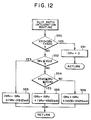
- the integral ISRx is computed for this purpose (see Step S5c of FIG. 17). Procedures of its computation will next be described with reference to FIG. 12 and FIG. 13.
- the electronic control unit 30 first finds in Step S50 whether the slip ratio SRx of each wheel is a value within a predetermined range of from XS12 to XS20 (for example, 12-20%) or not. If the slip ratio SRx is determined to fall within the predetermined range of from XS12 to XS20, a wheel cylinder for the wheel is considered to be supplied with hydraulic brake pressure sufficient to produce maximum friction. In such a case, it is unnecessary to detect the above-mentioned running on an extremely low- ⁇ road or advance from a low- ⁇ road to a high- ⁇ road. The routine then advances to Step S51, where the integral ISRx is reset to 0 to complete the routine. As long as the results of the determination in Step S50 are affirmative (t1 to t2, t5 to t6, and t7 to t8 in FIG. 13), Step S51 is repeatedly executed and the integral ISRx is maintained at 0.
- the integral ISRx so computed takes a positive value as is also apparent from FIG. 13 (t2 to t3, t4 to t5, and t8 to t9 in FIG. 13).
- the results of the determination in Step S54 are negative.
- FIG. 14 shows the illustrative membership function set for slip ratio integrals ISRx as the additional fuzzy input variable.
- Table 3 presents rules which are added when the slip ratio integral ISRx is PB.
- the slip ratio integral ISRx as an additional input variable in the fuzzy inference makes it possible, as is illustrated in FIG. 15(a), to detect each time-dependent variation of the slip ratio integral ISRx as a large value even if the slip ratio SRx undergoes small time-dependent variations.
- the slip ratio integral ISRx represents the length of a period in which the slip ratio SRx has been controlled outside the appropriate range described above.
- Table 4 illustrates rules to be added when the slip ratio integral ISRx is NB.
- the followings are examples of fuzzy rules when the slip ratio integral ISRx is NB.
- slip ratio integral ISRx as an additional input variable in the fuzzy inference makes it possible, as is illustrated in FIG. 16(a), to detect each advance from a low- ⁇ road to a high- ⁇ road because the slip ratio integral ISRx becomes much smaller than 0 (ISRx ⁇ 0).
- the wheel speed FVx is reduced earlier as indicated by numeral 4 on the curve 3 in FIG. 16(b). Owing to the difference between the actual vehicle body speed and the wheel speed FVx, frictional force is hence effectively produced between the road surface and the tire and braking is hence effected. The driver is therefore prevented from feeling idle-running.
- the motor direct-driven hydraulic unit (HU) 10 is arranged in the hydraulic line between each wheel cylinder and the master cylinder to control the hydraulic brake pressure.
- the application of the present invention is not limited to the use of such a hydraulic unit.
Description

(If the wheel acceleration FGx is NB and the slip ratio SRx is PB, the target pressure increase or decrease II is NB.)
(If the wheel acceleration FGx is Z0 and the slip ratio SRx is PS, the target pressure increase or decrease II is PS).

(If the wheel acceleration FGx is NB, the slip ratio SRx is PB and the wheel acceleration differential Jx is not PB, the target pressure increase or decrease II is NB in view of Table 1.)
(If the wheel acceleration FGx is NB, the slip ratio SRx is PB and the wheel acceleration differential Jx is PB, the target pressure increase or decrease II is Z0 in view of Table 2).

(If the wheel acceleration FGx is Z0, the slip ratio SRx is PM and the slip ratio integral ISRx is neither NB nor PB, the target pressure increase or decrease II is NO in view of Table 1.)
(If the wheel acceleration FGx is Z0, the slip ratio SRx is PM and the slip ratio integral ISRx is PB, the target pressure increase or decrease II is NS in view of Table 3.)

(If the wheel acceleration FGx is Z0, the slip ratio SRx is PM and the slip ratio integral ISRx is neither NB nor PB, the target pressure increase or decrease II is Z0 in view of Table 1.)
(If the wheel acceleration FGx is Z0, the slip ratio SRx is PM and the slip ratio integral ISRx is NB, the target pressure increase or decrease II is PB in view of Table 4).
Claims (5)
- An anti skid braking method for controlling, on the basis of a slip ratio (SRx) of a wheel and an acceleration (FGx) of the wheel, braking force to be applied to the wheel, which comprises:a slip ratio integrating step (48) in which, where the slip ratio is found to fall outside an appropriate range defined by upper and lower limit values during slip ratio computation, differences between the upper or lower limit value and individual slip ratio values of the wheel so computed are added to compute an integral (ISRx) of the differences; anda braking force computing step (46) in which, when the slip ratio falls below the lower limit value, the integral (ISRx) of the differences is greater than or equal to a predetermined value and the acceleration of the wheel is detected to be low, the control of the braking force is corrected to increase the braking force so that the slip ratio is allowed to fall back into the appropriate range; and, when the slip ratio exceeds the upper limit value, the integral (ISRx) is greater than or equal to the predetermined value and the acceleration of the wheel is detected to be low, the control of the braking force is corrected to decrease the braking force so that the slip ratio is allowed to fall back into the appropriate range.
- A method of claim 1 wherein when the slip ratio exceeds the upper limit value and any one of the differences exceeds the predetermined value, the predetermined value is added in place of the difference.
- A method of claim 1, wherein in the slip ratio integrating step (48), the integral is set to zero when the slip ratio returns to the appropriate range.
- A method of claim 1, wherein the braking force computing step (46) comprises computing, based on a fuzzy rule defining a relationship of a control value for enhancing the control of the braking force to bring the slip ratio back into the appropriate range with the slip ratio, the wheel acceleration and the integral, the control value from the slip ratio, the wheel acceleration and the integral.
- A method of claim 4, wherein the fuzzy rule comprises a first rule for a large value of the integral and a second rule for a small value of the integral; and the first rule defines the relationship of the control value with the slip ratio, the wheel acceleration and the integral in such a way that, compared with the second rule, the first rule more corrects the control of the braking force to bring the slip ratio back into the appropriate range.
Applications Claiming Priority (2)
| Application Number | Priority Date | Filing Date | Title |
|---|---|---|---|
| JP227027/92 | 1992-08-26 | ||
| JP4227027A JP2855987B2 (en) | 1992-08-26 | 1992-08-26 | Anti-skid braking method |
Publications (3)
| Publication Number | Publication Date |
|---|---|
| EP0585134A2 EP0585134A2 (en) | 1994-03-02 |
| EP0585134A3 EP0585134A3 (en) | 1995-04-19 |
| EP0585134B1 true EP0585134B1 (en) | 1998-10-28 |
Family
ID=16854373
Family Applications (1)
| Application Number | Title | Priority Date | Filing Date |
|---|---|---|---|
| EP93306795A Expired - Lifetime EP0585134B1 (en) | 1992-08-26 | 1993-08-26 | Anti-skid braking method |
Country Status (5)
| Country | Link |
|---|---|
| US (1) | US5474368A (en) |
| EP (1) | EP0585134B1 (en) |
| JP (1) | JP2855987B2 (en) |
| KR (1) | KR960008193B1 (en) |
| DE (1) | DE69321797T2 (en) |
Families Citing this family (21)
| Publication number | Priority date | Publication date | Assignee | Title |
|---|---|---|---|---|
| US5539642A (en) * | 1993-05-21 | 1996-07-23 | The Boeing Company | Fuzzy logic autobrake system for aircraft |
| US5627755A (en) * | 1994-09-09 | 1997-05-06 | Kelsey-Hayes Company | Method and system for detecting and compensating for rough roads in an anti-lock brake system |
| DE19510104C1 (en) * | 1995-03-20 | 1996-08-14 | Bayerische Motoren Werke Ag | ABS and / or ASC control system for motor vehicles |
| US5884987A (en) * | 1995-07-14 | 1999-03-23 | Nissan Diesel Co., Ltd. | Antilock brake device |
| US5669679A (en) * | 1996-03-04 | 1997-09-23 | General Motors Corporation | Brake system control |
| DE19717113B4 (en) * | 1996-04-26 | 2010-04-08 | DENSO CORPORATION, Kariya-shi | Brake force control system for motor vehicles |
| US6513886B1 (en) * | 1996-05-07 | 2003-02-04 | General Motors Corporation | Brake system control in which update of wheel speed normalization factors is selectively inhibited |
| JP3592444B2 (en) * | 1996-06-11 | 2004-11-24 | 株式会社ホンダエレシス | Anti-lock brake control device for vehicles |
| US6088646A (en) * | 1996-10-25 | 2000-07-11 | The Boeing Company | Fuzzy logic antiskid control system for aircraft |
| DE59914967D1 (en) | 1998-09-07 | 2009-04-09 | Pacifica Group Technologies Pt | Antilock braking system based on a fuzzy controller for an electromechanical vehicle braking system |
| GB2353573B (en) * | 1999-08-24 | 2002-01-02 | Bosch Gmbh Robert | Method and device for adjusting the braking action at the wheels of a motor vehicle |
| JP3731424B2 (en) * | 2000-02-10 | 2006-01-05 | トヨタ自動車株式会社 | BRAKE OPERATION SPEED DETECTING DEVICE AND VEHICLE BRAKE CONTROL DEVICE |
| KR100721384B1 (en) * | 2001-12-20 | 2007-05-23 | 주식회사 만도 | A signal processing unit of vehicles speed |
| DE102008011941A1 (en) * | 2008-02-29 | 2009-09-03 | Robert Bosch Gmbh | A method of determining a wheel reference speed of a wheel on a hydrostatic drive vehicle and apparatus for determining a wheel reference speed of a wheel of a hydrostatic drive vehicle |
| EP2351675B1 (en) * | 2008-11-25 | 2014-10-01 | Toyota Jidosha Kabushiki Kaisha | Travel control device for vehicle |
| DE102009027012A1 (en) * | 2009-06-18 | 2010-12-23 | Robert Bosch Gmbh | Method and device for determining a slip-related spatial error of a location of a motor vehicle when brake slip occurs |
| US8499848B2 (en) | 2011-08-05 | 2013-08-06 | Techtronic Outdoor Products Technology Limited | Gas tiller |
| CN102717786B (en) | 2012-06-11 | 2015-01-14 | 上海三一重机有限公司 | Control method for pavement self-adaptive antiskid antilock of electrically driven mine car |
| RU2540212C1 (en) * | 2013-07-09 | 2015-02-10 | федеральное государственное бюджетное образовательное учреждение высшего профессионального образования "Южно-Российский государственный технический университет (Новочеркасский политехнический институт)" | Acs device for train pneumoelectric brakes and method of its application |
| TR201613964A2 (en) * | 2016-10-05 | 2016-11-21 | Selcuk Karaosmanoglu | ZERO LOCK BRAKE SYSTEM |
| KR101958868B1 (en) * | 2017-02-23 | 2019-07-02 | 계명대학교 산학협력단 | System for predicting pedestrian intention for vehicle in night time and method thereof |
Family Cites Families (8)
| Publication number | Priority date | Publication date | Assignee | Title |
|---|---|---|---|---|
| JPS5245879B2 (en) * | 1972-05-15 | 1977-11-18 | ||
| US4779696A (en) * | 1986-07-24 | 1988-10-25 | Mazda Motor Corporation | Vehicle slip control apparatus |
| JP2681930B2 (en) * | 1987-06-27 | 1997-11-26 | 株式会社デンソー | Servo control device |
| JPH01132450A (en) * | 1987-11-17 | 1989-05-24 | Nissan Motor Co Ltd | Antiskid brake system |
| JPH01145255A (en) * | 1987-12-01 | 1989-06-07 | Fujitsu Ten Ltd | Antiskid controller |
| JPH0292763A (en) * | 1988-09-29 | 1990-04-03 | Omron Tateisi Electron Co | Antiskid device for vehicle |
| JPH0367761A (en) * | 1989-08-04 | 1991-03-22 | Aisin Seiki Co Ltd | Anti-skid control device |
| JPH03292247A (en) * | 1990-04-10 | 1991-12-24 | Mazda Motor Corp | Brake control device for vehicle |
-
1992
- 1992-08-26 JP JP4227027A patent/JP2855987B2/en not_active Expired - Fee Related
-
1993
- 1993-08-12 KR KR1019930015597A patent/KR960008193B1/en not_active IP Right Cessation
- 1993-08-23 US US08/110,689 patent/US5474368A/en not_active Expired - Fee Related
- 1993-08-26 DE DE69321797T patent/DE69321797T2/en not_active Expired - Fee Related
- 1993-08-26 EP EP93306795A patent/EP0585134B1/en not_active Expired - Lifetime
Also Published As
| Publication number | Publication date |
|---|---|
| DE69321797D1 (en) | 1998-12-03 |
| DE69321797T2 (en) | 1999-04-29 |
| KR940003797A (en) | 1994-03-12 |
| EP0585134A2 (en) | 1994-03-02 |
| US5474368A (en) | 1995-12-12 |
| JPH0672303A (en) | 1994-03-15 |
| JP2855987B2 (en) | 1999-02-10 |
| EP0585134A3 (en) | 1995-04-19 |
| KR960008193B1 (en) | 1996-06-20 |
Similar Documents
| Publication | Publication Date | Title |
|---|---|---|
| EP0585134B1 (en) | Anti-skid braking method | |
| EP0583988B1 (en) | Anti-skid braking method | |
| US6223116B1 (en) | Wheel slip angle detecting system for vehicle | |
| US5719565A (en) | Anti-skid controller having accurate road surface detection capabilities | |
| US5388896A (en) | Method for braking motor vehicle wheels while reducing a yawing moment of an antilock braking system | |
| US5332300A (en) | Process for controlling the stability of vehicles | |
| EP1317363B1 (en) | Rough road detection using suspension system information | |
| EP0943513B1 (en) | Apparatus for controlling behavior of vehicle using brakes | |
| EP1426258B1 (en) | Behaviour control system for vehicle | |
| US6236926B1 (en) | Vehicle behavior control device | |
| US5829847A (en) | Vehicle motion control system | |
| US20110273005A1 (en) | Motorcycle braking device | |
| US5505532A (en) | Skid control system | |
| US7066559B2 (en) | Brake pressure estimating apparatus and method | |
| US5103925A (en) | Rear wheel steering control system for vehicle | |
| US5855419A (en) | Process for controlling a distribution of braking force in a vehicle | |
| US5470136A (en) | Anti-skid control system | |
| US20030062768A1 (en) | System and method for vehicle stability enhancement control with surface estimate | |
| US5390991A (en) | Anti-skid control system | |
| US6349256B1 (en) | Turning behavior state detecting system for vehicle | |
| JP3772480B2 (en) | Anti-skid control device | |
| US5443583A (en) | Method for judging friction coefficient of road surface and method for anti-skid brake control using said method | |
| US5190360A (en) | Control method for an antiskid braking system | |
| JP2903888B2 (en) | Anti-skid braking method | |
| JP3426513B2 (en) | Vehicle oversteer state detection device |
Legal Events
| Date | Code | Title | Description |
|---|---|---|---|
| PUAI | Public reference made under article 153(3) epc to a published international application that has entered the european phase |
Free format text: ORIGINAL CODE: 0009012 |
|
| AK | Designated contracting states |
Kind code of ref document: A2 Designated state(s): DE FR GB |
|
| PUAL | Search report despatched |
Free format text: ORIGINAL CODE: 0009013 |
|
| AK | Designated contracting states |
Kind code of ref document: A3 Designated state(s): DE FR GB |
|
| 17P | Request for examination filed |
Effective date: 19950926 |
|
| 17Q | First examination report despatched |
Effective date: 19960924 |
|
| GRAG | Despatch of communication of intention to grant |
Free format text: ORIGINAL CODE: EPIDOS AGRA |
|
| GRAG | Despatch of communication of intention to grant |
Free format text: ORIGINAL CODE: EPIDOS AGRA |
|
| GRAG | Despatch of communication of intention to grant |
Free format text: ORIGINAL CODE: EPIDOS AGRA |
|
| GRAH | Despatch of communication of intention to grant a patent |
Free format text: ORIGINAL CODE: EPIDOS IGRA |
|
| GRAH | Despatch of communication of intention to grant a patent |
Free format text: ORIGINAL CODE: EPIDOS IGRA |
|
| GRAA | (expected) grant |
Free format text: ORIGINAL CODE: 0009210 |
|
| AK | Designated contracting states |
Kind code of ref document: B1 Designated state(s): DE FR GB |
|
| REF | Corresponds to: |
Ref document number: 69321797 Country of ref document: DE Date of ref document: 19981203 |
|
| ET | Fr: translation filed | ||
| PLBE | No opposition filed within time limit |
Free format text: ORIGINAL CODE: 0009261 |
|
| STAA | Information on the status of an ep patent application or granted ep patent |
Free format text: STATUS: NO OPPOSITION FILED WITHIN TIME LIMIT |
|
| 26N | No opposition filed | ||
| REG | Reference to a national code |
Ref country code: GB Ref legal event code: IF02 |
|
| REG | Reference to a national code |
Ref country code: FR Ref legal event code: CA |
|
| PGFP | Annual fee paid to national office [announced via postgrant information from national office to epo] |
Ref country code: FR Payment date: 20050809 Year of fee payment: 13 |
|
| PGFP | Annual fee paid to national office [announced via postgrant information from national office to epo] |
Ref country code: DE Payment date: 20050818 Year of fee payment: 13 |
|
| PGFP | Annual fee paid to national office [announced via postgrant information from national office to epo] |
Ref country code: GB Payment date: 20050824 Year of fee payment: 13 |
|
| PG25 | Lapsed in a contracting state [announced via postgrant information from national office to epo] |
Ref country code: DE Free format text: LAPSE BECAUSE OF NON-PAYMENT OF DUE FEES Effective date: 20070301 |
|
| GBPC | Gb: european patent ceased through non-payment of renewal fee |
Effective date: 20060826 |
|
| REG | Reference to a national code |
Ref country code: FR Ref legal event code: ST Effective date: 20070430 |
|
| PG25 | Lapsed in a contracting state [announced via postgrant information from national office to epo] |
Ref country code: GB Free format text: LAPSE BECAUSE OF NON-PAYMENT OF DUE FEES Effective date: 20060826 |
|
| PG25 | Lapsed in a contracting state [announced via postgrant information from national office to epo] |
Ref country code: FR Free format text: LAPSE BECAUSE OF NON-PAYMENT OF DUE FEES Effective date: 20060831 |