EP0585097A2 - Mechanische Packermuffe zum Zementieren - Google Patents
Mechanische Packermuffe zum Zementieren Download PDFInfo
- Publication number
- EP0585097A2 EP0585097A2 EP93306671A EP93306671A EP0585097A2 EP 0585097 A2 EP0585097 A2 EP 0585097A2 EP 93306671 A EP93306671 A EP 93306671A EP 93306671 A EP93306671 A EP 93306671A EP 0585097 A2 EP0585097 A2 EP 0585097A2
- Authority
- EP
- European Patent Office
- Prior art keywords
- sleeve
- housing
- cementing
- closure sleeve
- packer element
- Prior art date
- Legal status (The legal status is an assumption and is not a legal conclusion. Google has not performed a legal analysis and makes no representation as to the accuracy of the status listed.)
- Ceased
Links
Images






Classifications
-
- E—FIXED CONSTRUCTIONS
- E21—EARTH OR ROCK DRILLING; MINING
- E21B—EARTH OR ROCK DRILLING; OBTAINING OIL, GAS, WATER, SOLUBLE OR MELTABLE MATERIALS OR A SLURRY OF MINERALS FROM WELLS
- E21B33/00—Sealing or packing boreholes or wells
- E21B33/10—Sealing or packing boreholes or wells in the borehole
- E21B33/13—Methods or devices for cementing, for plugging holes, crevices or the like
- E21B33/14—Methods or devices for cementing, for plugging holes, crevices or the like for cementing casings into boreholes
- E21B33/146—Stage cementing, i.e. discharging cement from casing at different levels
-
- E—FIXED CONSTRUCTIONS
- E21—EARTH OR ROCK DRILLING; MINING
- E21B—EARTH OR ROCK DRILLING; OBTAINING OIL, GAS, WATER, SOLUBLE OR MELTABLE MATERIALS OR A SLURRY OF MINERALS FROM WELLS
- E21B33/00—Sealing or packing boreholes or wells
- E21B33/10—Sealing or packing boreholes or wells in the borehole
- E21B33/12—Packers; Plugs
- E21B33/128—Packers; Plugs with a member expanded radially by axial pressure
-
- E—FIXED CONSTRUCTIONS
- E21—EARTH OR ROCK DRILLING; MINING
- E21B—EARTH OR ROCK DRILLING; OBTAINING OIL, GAS, WATER, SOLUBLE OR MELTABLE MATERIALS OR A SLURRY OF MINERALS FROM WELLS
- E21B34/00—Valve arrangements for boreholes or wells
- E21B34/06—Valve arrangements for boreholes or wells in wells
- E21B34/14—Valve arrangements for boreholes or wells in wells operated by movement of tools, e.g. sleeve valves operated by pistons or wire line tools
- E21B34/142—Valve arrangements for boreholes or wells in wells operated by movement of tools, e.g. sleeve valves operated by pistons or wire line tools unsupported or free-falling elements, e.g. balls, plugs, darts or pistons
Definitions
- the present invention relates generally to a cementing tool and, more particularly, to an improved stage cementing packer collar used for cementing casing in oil and gas wells.
- cementing the casing in the well bore in separate stages, beginning at the bottom of the well and working upwards. Cementing the casing in separate stages ensures less contamination throughout the zones to be cemented, and reduces the possibility of lost circulation due to excessive hydrostatic pressure.
- the process is carried out by placing cementing tools, which are primarily valve ports. in the casing or between joints of casing at one or more locations in the well bore, flowing cement through the bottom of the casing, up the annulus to the lowest cementing tool, closing off the bottom, opening the cementing tool, and then flowing cement through the cementing tool up the annulus to the next upper stage, and repeating this process until all stages of the well are cemented.
- cementing tools which are primarily valve ports.
- Cementing tools used for multi-stage cementing usually have two internal sleeves, both of which are usually shear-pinned initially in an upper position, closing the cementing ports in the tool.
- a plug is dropped or displaced down the casing and seated on the lower sleeve. Fluid pressure is then increased in the casing until sufficient force is developed on the plug and sleeve to shear the shear pins and move the lower sleeve to the position uncovering the cementing ports.
- Cement is then pumped down the casing and out the ports into the annulus.
- another plug is placed in the casing behind the cement and displaced down the casing to seat on the upper sleeve. The pressure is increased on the second plug until the shear pins holding it are severed and the upper sleeve is moved down to close the cementing ports, thereby terminating that particular stage of the cement job.
- Multistage cementing tools may also include a packer element for sealing the annular space between the casing (which the cementing tool is a part of) and the borehole, or between the casing and another string of casing.
- Multi-stage cementing tools containing a packer element are commonly referred to as stage cementing packer collars.
- the packer element of a stage cementing packer is designed to support the cement displaced through the cementing ports of the stage cementing packer while protecting formations below the packer collar from the hydrostatic pressure of the cement.
- the packer element is designed to seal the annular space against upward migration of fluids from formations beneath the packer collar.
- stage cementing packer collar by which several improvements over previous stage cementing packer collars can be obtained. These improvements include: (1) shorter length; (2) a single piece housing as opposed to a two or three piece housing with welds; (3) the housing has a smaller outer diameter allowing the use of thicker-walled packer elements; (4) an option of opening the packer collar with a plug or with internal casing pressure as opposed to a plug only; (5) a smooth bore through the internal diameter of the housing after the packer collar has been drilled out; and (6) no internal closing sleeve.
- a cementing tool apparatus comprising:
- the stage cementing packer collar of the present invention can be more compact than prior designs and thus easier to handle and make-up into the casing string.
- the single piece housing increases the structural integrity of the housing over prior art housings that are welded together.
- the use of thicker-walled packer elements allows a given size stage cementing packer collar of the present invention to seal a larger annular space than the same size prior art tool. In other words, a thicker packer element will seal a larger annular space than a thinner packer element.
- the cementing ports in the cementing tool of the present invention may be opened by internal casing pressure alone or in conjunction with a plug. Opening the cementing ports with casing pressure only saves valuable rig time in the operation of the tool. At the same time, the capability of opening the cementing ports using the conventional plug method serves as a valuable back up system. As a result, the present invention offers a system that is operationally faster and more reliable than conventional stage cementing packer collars.
- the cementing tool of the present invention has an external closing sleeve for closing the cementing ports after the cementing job is completed.
- a smoother bore through the internal diameter of the housing remains after drill out of the packer collar. This facilitates the subsequent running of tools through the packer collar and reduces the likelihood of tool hang-up inside the packer collar, which is a problem with prior art packer collars.
- the interlocking means preferably interlocks the operating sleeve and closure sleeve together with common longitudinal movement relative to said housing throughout the entire movement of said operating sleeve from its first position to its second position without any lost motion of the operating sleeve relative to the closure sleeve.
- the closure sleeve itself is longitudinally hydraulically balanced and no unbalanced hydraulic force acts thereon at any time.
- the cementing tool is designed for quick and easy drill-out of the internal components of the tool after the cementing job is completed thus leaving a smooth, unobstructed bore through the tool which is substantially free of any obstruction which can hang up other tools which will subsequently be run therethrough.
- FIG. 1 is an elevational sectioned view of one embodiment of the invention by way of example only, utilizing a hydraulically operated lower internal opening sleeve.
- FIG. 2 is an elevational sectioned view of a second embodiment of the invention by way of example only, utilizing a plug actuated lower internal opening sleeve.
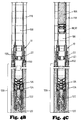
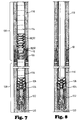
- FIGS. 3-8 comprise a sequential series of views illustrating the use of the cementing tool of FIG. 1 to stage cement a well.
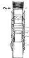
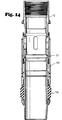
- FIGS. 9-14 represent the cementing tool of FIG. 1 during the various phases of a stage cement job as illustrated in FIGS. 3-8.
- FIG. 1 an embodiment of a cementing tool apparatus of the present invention is shown and generally designated by the numeral 10.
- the cementing tool 10 includes a tubular housing 12 having an upper end 14 and a lower end 16 with an inner passage 18 defined longitudinally therethrough from the upper end 14 to the lower end 16.
- the tubular housing 12 has a radially outer surface 20.
- the housing 12 also includes a wall 24 having one or more cementing ports 22 disposed therethrough.
- the wall 24 also has three longitudinal slots disposed therethrough, one of which slots is shown in FIG. 1 and designated as 26.
- the cementing tool 10 includes an outer, external closure sleeve 30 which is concentrically, closely, slidably received about the outer surface 20 of the housing 12.
- the closure sleeve 30 is movable relative to the housing 12 between an open position as seen in FIG. 1, and a closed position wherein the cementing port 22 is closed by closure sleeve 30.
- the closure sleeve 30 can be described as an external sleeve and has a generally cylindrical radially outer surface which is at least partially exposed to the well annulus 124.
- Cementing tool 10 includes an inner operating sleeve 32 which is slidably received in an inner bore 34 of housing 12.
- the operating sleeve 32 is slidable between a first position relative to housing 12 as seen in FIG. 1, and a second position corresponding to the closed position of closure sleeve 30 as schematically illustrated in FIG. 13.
- Three pins extend through the slots in wall 24 and are fixably connected to the operating sleeve 32 and the closure sleeve 30 to interlock the operating sleeve 32 and closure sleeve 30 for common longitudinal movement relative to the housing 12 throughout the entire movement of the operating sleeve 32 from its first position to its second position. Since the pins 36 and 38 fixedly connect operating sleeve 32 to closure sleeve 30, there is no lost longitudinal motion of the operating sleeve 32 relative to the closure sleeve 30 as the operating sleeve 32 moves downward to close the cementing port 22 with the closure sleeve 30.
- the pins 36 and 38 are threadedly engaged with threaded radial bores such as 40 and 42 extending through the operating sleeve 32 and tightly engage an internal annular groove 44 cut in the inner bore 46 of closure sleeve 30.
- the pins such as 36 and 38 and their engagement with the operating sleeve 32 and closure sleeve 30 can all be referred to as a mechanical interlocking means extending through the slots in wall 24, such as 26, and operably associated with both the operating sleeve 32 and the closure sleeve 30 for transferring a closing force from the operating sleeve 32 to the closure sleeve 30 and thereby moving the closure sleeve 30 to its closed position as the operating sleeve 32 moves from its first position to its second position.
- Pins 36 and 38 also serve to hold sleeve 32 so that it will not rotate as sleeve 32 is later drilled out of housing 12 after the cementing job is completed.
- the cementing tool 10 includes an upper sliding seal 48 and a lower sliding seal 50 disposed in annular grooves cut in the bore 46 of closure sleeve 30 near its upper and lower ends.
- the upper and lower sliding seals 48 and 50 include an O-ring held between two annular backup sealing rings 51.
- the apparatus 10 can be said to have two sliding seals between the closure sleeve 30 and the outer surface 20 of housing 12, one of said seals 48 being located above the cementing port 22 and the other seal 50 being located below the cementing port 22 when the closure sleeve 30 is in its said closed position.
- closure sleeve 30 can be described as being longitudinally hydraulically balanced.
- the inner passageway 18 of housing 12 is always in fluid pressure communication with the bore 46 of closure sleeve 30 between its upper and lower seals 48 and 50.
- the cementing tool 10 further includes an internal lower opening sleeve 49 slidably received in the bore 34 of housing 12 below the operating sleeve 32.
- the opening sleeve 49 is slidable between a closed position as shown in FIG. 1 wherein the cementing port 22 is closed by the opening sleeve 49 and an open position, such as is schematically illustrated in FIG. 4A and FIG. 10 wherein the cementing port 22 is uncovered by the opening sleeve 49 as the opening sleeve moves downward relative to housing 12. It is noted that when the opening sleeve 49 is in its closed position as is seen in FIG. 1 and the operating sleeve 32 is simultaneously in its first position as shown in FIG. 1, the inner passage 18 of housing 12 is in fluid pressure communication with the bore 46 of closure sleeve 30 between its sliding seals 48 and 50.
- Cementing tool 10 includes elastomeric packer element 150 which is concentrically and closely received about the outer surface 20 of housing 12.
- Packer element 150 is preferably cylindrical in shape and abuts bottom shoe 151 on cementing tool 10.
- Bottom shoe 151 is threadedly connected to the lower end of housing 12.
- Bottom shoe 151 may be manufactured with a tapered lower end as shown in FIG. 1, which facilitates the lowering of cementing tool 10 into the well bore.
- Packer element 150 may have upper and lower support rings located on the external upper and lower edges of the packer element and shown as 153, which support the elastomeric packer element during the sealing operation.
- Cementing tool 10 further includes an external setting sleeve 155 for compressing packer element 150.
- Setting sleeve 155 preferably is an elongate cylindrical sleeve which is slidably mounted about cementing tool 10 as shown in FIG. 1. It includes a thin wall upper section 157 which is slidably received on the external surface of closure sleeve 30.
- Setting sleeve 155 includes a thicker wall lower section, to which setting sleeve shoe 159 is threadedly attached.
- Setting sleeve shoe 159 is a tapered ring which abuts the upper end of packer element 150.
- Setting sleeve 155 contains upper sliding seal 160 and lower sliding seal 161, typically O-ring seals, which are located in grooves cut in the internal bore of the setting sleeve.
- Upper seal 160 engages the external surface of closure sleeve 30, while lower seal 161 engages the outer surface 20 of housing 12, so that a differential area is defined between seals 160 and 161.
- Setting sleeve 155 includes, preferably, two rupture disks, one of which is shown in FIG. 1 as 162.
- the rupture disks are positioned inside ports disposed through the lower section of setting sleeve 155.
- the rupture disks effectively seal the ports while the rupture disks are intact.
- Radially displaced from the rupture disks is a pressure equalizing valve 164, which monitors the pressure differential between the fluid pressure outside the setting sleeve and inside the setting sleeve.
- Pressure equalizing valve 164 is a one way valve which controls the pressure differential acting on the rupture disks by allowing annular fluid to pass into the internal bore of the setting sleeve 155 when the annular pressure exceeds the pressure inside the setting sleeve.
- the opening sleeve 49 in the embodiment of FIG. 1 is a hydraulically operated sleeve. It includes a reduced diameter lower portion 51 which is slidably received within a bore 52 of an anchor ring 54 which is fixedly attached to the inner bore 34 of housing 12 such as by lock ring 55.
- An O-ring seal 56 seals between anchor ring 54 and housing 12.
- Opening sleeve 49 carries an upper annular sliding seal 58 which engages the bore 34 of housing 12, and carries a lower annular sliding seal 60 which engages the reduced diameter bore 52 of anchor ring 54, so that a differential area is defined between seals 58 and 60. Opening sleeve 49 is initially shear pinned in its closed position as shown in FIG. 1 by a plurality of shear pins 62 which are threaded through the wall of housing 12 and engage holes in the opening sleeve.
- the interior of the casing string in which the apparatus 10 is located can be closed off below the cementing tool 10 so that a high fluid pressure can be applied to the passage 18 through housing 12 which pressure will act downward on the differential area between seals 58 and 60 until the force exceeds that which can be held by the shear pins 62. Then the shear pins 62 will shear and the downward acting differential pressure will move the opening sleeve 49 downward until a lower shoulder 66 thereof engages the anchor ring 54. At that point, the upper seal 58 is located below cementing port 22 so that the cementing port 22 is open to the passage 18 through housing 12.
- opening sleeve 49 may be activated by a plug means such as a free fall plug or a pump down plug which seals the opening through the opening sleeve.
- the plug will land on the tapered profile 170 on the top of opening sleeve 49.
- fluid pressure is applied to passage 18 until the force acting on the plug exceeds that which can be held by the shear pins 62.
- the shear pins Once the shear pins have sheared, the pressure will move opening sleeve 49 downward until it engages anchor ring 54, thereby exposing cementing port 22.
- the plug means may be configured to prevent rotation with respect to opening sleeve 49 to facilitate drill out after the cement job has been completed.
- a non-rotating engagement is provided between the shoulder 66 of opening sleeve 49 and the upper end of anchor ring 54 by a lug and recess type interlocking structure (not shown) similar to lug 84 and recess 86 described below.
- the fluid pressure will act downward on the differential area between seals 160 and 161 on the setting sleeve 155.
- the downward force exerted on the setting sleeve will cause the setting sleeve to move downward toward the stationary bottom shoe 151.
- the downward movement of setting sleeve 155 will compress the elastomeric packer element 150 against bottom shoe 151 until the packer element expands to the borehole wall or to the outer casing, effectively sealing the annular space, and protecting the formations below the cementing tool from the hydrostatic pressure of the subsequent cement job.
- Lock ring 165 is located in a tapered groove cut into the internal bore of setting sleeve 155.
- Lock ring 165 is configured to the tapered groove cut into the internal bore of the setting sleeve such that upward movement of setting sleeve is prevented by frictional interference with the lock ring.
- the lock ring is tapered to allow downward movement of the setting sleeve with respect to housing 12 while preventing the upward movement of the setting sleeve.
- lock ring 165 is operable to lock the setting sleeve after the latter has compressed the packer element into the sealing position.
- the closure sleeve 30 is closed by means of the operating sleeve 32.
- a closing force is applied to the operating sleeve 32 by a plug means which will seat on an annular seat 68 defined on the upper end of operating sleeve 32.
- the operating sleeve is initially held in place relative to housing 12 by a plurality of shear pins 70 which are threaded through the operating sleeve 32 and received in a groove (not shown) in the bore 34 of housing 12.
- An upper sliding O-ring 74 seals between the operating sleeve 32 and the housing 12.
- the closure sleeve 30 carries an inwardly biased locking ring 76 in a groove contained near its lower end.
- the locking ring 76 will snap into an outer annular groove 78 defined in the housing 12 to mechanically lock the closure sleeve 30 in its closed position relative to housing 12.
- Upper external support ring 80 is fixedly attached to the housing 12 at or near the position of the upper end of the closure sleeve 30 when the closure sleeve is in its open position.
- the support ring 80 along with bottom shoe 151 and setting sleeve shoe 159 have outside diameters equal to or greater than the outside diameter of setting sleeve 155 so that if the tool 10 is placed against the wall of a casing, the ring 80 and shoes 151 and 159 will hold the tool such that the setting sleeve 155 can still slide downward relative to housing 12 without binding against the casing.
- Support ring 80 and shoes 151 and 159 also provide protection for tool 10 as the casing string incorporating tool 10 is run into the borehole.
- Packer element 150 may be manufactured to various diameters so that different size annuluses may be sealed with a given size cementing tool. In general, the packer element diameter will increase as the size of the annular space to be sealed increases. Accordingly, support ring 80 and shoes 151 and 159 may be manufactured in a variety of sizes as well.
- the opening sleeve 49 has an upward extending lug 84 which will be received within a downward facing recess 86 in the lower end of operating sleeve 32 when the operating sleeve 32 moves downward to a position corresponding to the closed position of closure sleeve 30. This prevents the operating sleeve 32 from rotating relative to the opening sleeve 49 and housing 12 at a later time when the internal components are drilled out of the housing 12.
- the cementing tool 10 of FIG. 1 is particularly designed for use with a cementing plug means 88 (see FIGS. 4-7) including a bottom plug 90 and a top plug 92. As is further described below, the cementing plug means 88 is used in connection with the second stage of cement which is pumped through the cementing port 22 of cementing tool 10.
- the cementing tool 10 and its associated cementing plug means 88 may be designed so that the cementing plug means 88 will not rotate relative to the housing 12 of cementing tool 10 when the cementing plug means 88 and other internal components of the cementing tool 10 are drilled out of the housing 12 after the cementing job is completed.
- This non-rotatable feature preferably is like that shown in U.S. Patent No. 5,038,862 to Giroux et al., which is incorporated herein by reference.
- the bottom plug 90 is utilized to separate the bottom of a column of cement 106 from well fluids 108 located therebelow to prevent contamination of the cement prior to the time it is pumped through the cementing port 22.
- the bottom cementing plug 90 as best seen in the somewhat schematic sectioned view of FIG. 5 has a passage 110 therethrough which is initially closed by a rupture disc or diaphragm schematically illustrated as 112.
- the top plug 92 separates the upper extremity of the cement column 106 from a working fluid 114 thereabove.
- the top plug 92 is a closed plug having no passage therethrough, and. when it engages bottom plug 90 as schematically illustrated in FIG. 7, the top plug 92 seals against bottom plug 90 closing the passage 110 therethrough.
- a non-rotatable engagement may be provided between top plug 92 and bottom plug 90 to prevent top plug 92 from rotating relative to bottom plug 90 when the plugs are later drilled out.
- This non-rotatable engagement between the top and bottom plugs preferably is like that shown in U.S. Pat. No. 4,858,687 to Watson et al. which is incorporated herein by reference.
- the shear pins 70 must be designed such that they can safely withstand the downward force applied thereto when pressure is applied to rupture the rupture disc 112 to bottom plug 90, and the shear pins 70 must also be designed so that they will shear and release the operating sleeve 32 at a predetermined pressure after the top plug 92 seats against bottom plug 90.
- the shear pins 70 may be collectively referred to as a releasable retaining means 70 for initially retaining the operating sleeve 32 in place relative to housing 12 with the cementing port 22 open as the rupture disc 112 of bottom cementing plug 90 is ruptured to open the passage 110 through the bottom cementing plug 90. It is also noted that the apparatus 10 could be used with only a top cementing plug similar to plug 92.
- FIGS. 3-8 The major steps of a multi-stage well cementing job utilizing the cementing tool 10 are schematically illustrated in FIGS. 3-8.
- FIGS. 9-14 illustrate the cementing tool 10 in more detail during the various phases of a stage cement job as shown in FIGS. 3-8.
- a well casing string 116 is located within a well bore 118.
- the cementing tool 10 is placed in the casing string 116 before it is run into the well bore 118. It may be inserted between standard threaded connections of the casing at the desired locations of various cementing stages. A number of cementing stages are possible as long as each cementing tool 10 in the casing string 116 has a smaller inner diameter than the cementing tool immediately above it.
- the first or lowermost stage of cementing may be accomplished through a bottom opening 120 in a float shoe 122 arranged at the lower end of the casing string 116.
- the cement flows downward through casing string 116 out the opening 120 and up into a well annulus 124 defined between the casing string 116 and well bore 118.
- a wiper plug 126 is inserted behind the first stage of cement slurry and displacing fluid is pumped behind the wiper plug 126 to displace the cement from the casing string 116.
- FIG. 9 shows the position of the various components of cementing tool 10 during the step illustrated in FIG. 3.
- the wiper plug 126 will seat in the float shoe 122 thus stopping flow of the first stage of cement 128 up into the annulus 124.
- the first stage 128 of cement will extend to some point below the cementing port 22 of the cementing tool 10.
- cement 106 for the second stage cementing can be pumped down the casing 116 with the displacing fluids located therebelow being circulated through the cementing port 22, through opening 127 and back up the annulus 124 as shown in FIG. 4C.
- a bottom cementing plug 90 is run below the cement 106 and a top plug 92 is run at the upper extremity of the cement 106.
- FIG. 12 represents cementing tool 10 during the steps illustrated by FIGS. 4C, 5, and 6.
- FIG. 7 illustrates cementing tool 10 with closure sleeve 30 in its closed position.
- the cementing plugs 90 and 92, and the operating sleeve 32 and opening sleeve 49 and anchor ring 54 can all be drilled out of the casing 12 leaving a smooth bore through the cementing tool 10 as schematically illustrated in FIG. 8 and FIG. 14.
- the components to be drilled out of housing 12 including the operating sleeve 32, opening sleeve 49 and anchor ring 54 are all made from easily drillable materials such as aluminum.
- the cementing plugs 90 and 92 may be made of aluminum, plastic and/or rubber components which are easily drilled.
- FIG. 2 illustrates an alternative embodiment of the cementing tool of the present invention which is shown and generally designated by the numeral 200.
- the cementing tool 200 differs primarily in that its opening sleeve is not hydraulically actuated but instead is designed to be actuated by engagement of a pump-down plug or free-all plug which seals the opening through the opening.sleeve.
- the cementing tool 200 includes a housing 202.
- An operating sleeve 204 is received therein.
- a closure sleeve 206 is received about the housing 202.
- a series of pins such as 208 and 210 extend through slots in housing 202 to fixedly connect the operating sleeve 204 and closure sleeve 206.
- Shear pins 216 initially hold the operating sleeve 204 in place relative to housing 202.
- An annular seat 218 is defined upon the upper end of operating sleeve 204 for engagement with a cementing plug.
- a cementing port 220 is disposed through the housing 202.
- An opening sleeve 222 is located within the housing 202 and is initially held in place relative thereto by shear pins 224.
- Upper and lower sliding O-ring seals 226 and 228 are carried by opening sleeve 222.
- the seals 226 and 228 are above and below, respectively, the cementing port 220 when the opening sleeve 222 is in its initial closed position as shown in FIG. 2.
- the opening sleeve 222 has an annular seat 230 defined on its upper end which is constructed for engagement with a free-fall or pump-down plug (not shown).
- a free-fall or pump-down plug engages seat 230 fluid pressure applied thereto acts downward to shear the shear pins 224 so that the plug and opening sleeve 222 can move downward until the opening sleeve 222 abuts an anchor ring 232.
- the upper O-ring seal 226 is then located below cementing port 220 so that fluid may be pumped through the cementing port 220 in a manner similar to that previously described with regard to the embodiment of FIG. 1.
- Cementing tool 200 includes packer element 250 which is concentrically located about the outer surface of housing 202. The lowermost end of packer element 250 abuts bottom shoe 251.
- Cementing tool 200 further includes an external setting sleeve 255 for compressing packer element 250.
- External setting sleeve 255 has preferably two rupture disks, one of which is shown in FIG. 2 as 262, and a pressure equalizing valve 264.
- Fluid pressure exerted inside housing 202 will be communicated through cementing port 220 and act on external setting sleeve 255 in a manner similar to that previously described with regard to the embodiment of FIG. 1, to compress packer element 250 into sealing position. Gradually increasing the pressure will rupture a rupture disk in external setting sleeve 255, thus providing an opening whereby fluid inside housing 202 may be pumped into the annulus about tool 202.
- the rupture disks provide a means for communicating with the annulus about the cementing tool after the setting sleeve has set the packer element.
- the operation of setting sleeve 255 is similar to the manner previously described with regard to the embodiment of FIG. 1.
Landscapes
- Life Sciences & Earth Sciences (AREA)
- Engineering & Computer Science (AREA)
- Geology (AREA)
- Mining & Mineral Resources (AREA)
- Physics & Mathematics (AREA)
- Environmental & Geological Engineering (AREA)
- Fluid Mechanics (AREA)
- General Life Sciences & Earth Sciences (AREA)
- Geochemistry & Mineralogy (AREA)
- Consolidation Of Soil By Introduction Of Solidifying Substances Into Soil (AREA)
- Earth Drilling (AREA)
Applications Claiming Priority (2)
| Application Number | Priority Date | Filing Date | Title |
|---|---|---|---|
| US934151 | 1986-11-24 | ||
| US07/934,151 US5279370A (en) | 1992-08-21 | 1992-08-21 | Mechanical cementing packer collar |
Publications (2)
| Publication Number | Publication Date |
|---|---|
| EP0585097A2 true EP0585097A2 (de) | 1994-03-02 |
| EP0585097A3 EP0585097A3 (de) | 1995-01-11 |
Family
ID=25465051
Family Applications (1)
| Application Number | Title | Priority Date | Filing Date |
|---|---|---|---|
| EP93306671A Ceased EP0585097A3 (de) | 1992-08-21 | 1993-08-23 | Mechanische Packermuffe zum Zementieren. |
Country Status (3)
| Country | Link |
|---|---|
| US (1) | US5279370A (de) |
| EP (1) | EP0585097A3 (de) |
| NO (1) | NO932951L (de) |
Cited By (8)
| Publication number | Priority date | Publication date | Assignee | Title |
|---|---|---|---|---|
| GB2365465A (en) * | 2000-06-21 | 2002-02-20 | Baker Hughes Inc | Cement diverter for cementing a junction. |
| WO2005033470A1 (en) * | 2003-10-01 | 2005-04-14 | Baker Hughes Incorporated | Model hccv hydrostatic closed circulation valve |
| EP1619350A1 (de) * | 1997-09-12 | 2006-01-25 | Weatherford/Lamb, Inc. | Ein Stopfen zur Benutzung in Bohrlöchern, eine Vorrichtung zur Aufnahme dieses Stopfens, ein Stopfen Landesystem und Verfahren zum Ementieren Von Rohren in Bohrlöchern |
| US7464758B2 (en) | 2002-10-02 | 2008-12-16 | Baker Hughes Incorporated | Model HCCV hydrostatic closed circulation valve |
| CN102094596A (zh) * | 2010-12-30 | 2011-06-15 | 中国海洋石油总公司 | 一种智能井井下滑套锁紧装置及其操作方法 |
| CN109296338A (zh) * | 2018-12-07 | 2019-02-01 | 柳江 | 一种自解体式可溶桥塞 |
| CN110905442A (zh) * | 2019-12-12 | 2020-03-24 | 中国石油集团渤海钻探工程有限公司 | 一种套管外环空水泥浆填充封隔器 |
| WO2022231722A1 (en) * | 2021-04-29 | 2022-11-03 | Halliburton Energy Services, Inc. | Stage cementer packer |
Families Citing this family (45)
| Publication number | Priority date | Publication date | Assignee | Title |
|---|---|---|---|---|
| US5511617A (en) * | 1994-08-04 | 1996-04-30 | Snider; Philip M. | Apparatus and method for temporarily plugging a tubular |
| US5526878A (en) * | 1995-02-06 | 1996-06-18 | Halliburton Company | Stage cementer with integral inflation packer |
| US6082451A (en) * | 1995-04-26 | 2000-07-04 | Weatherford/Lamb, Inc. | Wellbore shoe joints and cementing systems |
| US5553667A (en) * | 1995-04-26 | 1996-09-10 | Weatherford U.S., Inc. | Cementing system |
| GB9525044D0 (en) * | 1995-12-07 | 1996-02-07 | Nodeco Ltd | Plugs for downhole tools |
| US5738171A (en) * | 1997-01-09 | 1998-04-14 | Halliburton Company | Well cementing inflation packer tools and methods |
| US6651743B2 (en) | 2001-05-24 | 2003-11-25 | Halliburton Energy Services, Inc. | Slim hole stage cementer and method |
| US20070227730A1 (en) * | 2005-09-15 | 2007-10-04 | Enventure Global Technology | Apparatus for radially expanding and plastically deforming a tubular member |
| US7451815B2 (en) * | 2005-08-22 | 2008-11-18 | Halliburton Energy Services, Inc. | Sand control screen assembly enhanced with disappearing sleeve and burst disc |
| NO326067B1 (no) * | 2006-12-20 | 2008-09-08 | Smart Intervention As | Apparat for lekkasjetesting og/eller trykkproving av et parti av et ror samt framgangsmate ved bruk av samme |
| US8215404B2 (en) * | 2009-02-13 | 2012-07-10 | Halliburton Energy Services Inc. | Stage cementing tool |
| US8267174B2 (en) * | 2009-08-20 | 2012-09-18 | Halliburton Energy Services Inc. | Internal retention mechanism |
| US8230926B2 (en) * | 2010-03-11 | 2012-07-31 | Halliburton Energy Services Inc. | Multiple stage cementing tool with expandable sealing element |
| US8967255B2 (en) | 2011-11-04 | 2015-03-03 | Halliburton Energy Services, Inc. | Subsurface release cementing plug |
| US9476273B2 (en) * | 2012-01-13 | 2016-10-25 | Halliburton Energy Services, Inc. | Pressure activated down hole systems and methods |
| US8708056B2 (en) * | 2012-03-07 | 2014-04-29 | Halliburton Energy Services, Inc. | External casing packer and method of performing cementing job |
| US9243480B2 (en) * | 2012-10-31 | 2016-01-26 | Halliburton Energy Services, Inc. | System and method for activating a down hole tool |
| CN103556970A (zh) * | 2013-11-08 | 2014-02-05 | 西安航威石化设备有限公司 | 组合式自锁胶塞 |
| WO2015085169A2 (en) * | 2013-12-05 | 2015-06-11 | Weatherford/Lamb, Inc. | Toe sleeve isolation system for cemented casing in borehole |
| MX380668B (es) | 2014-02-11 | 2025-03-12 | Halliburton Energy Services Inc | Cono de expansion para una herramienta de fondo de pozo. |
| US9970258B2 (en) * | 2014-05-16 | 2018-05-15 | Weatherford Technology Holdings, Llc | Remotely operated stage cementing methods for liner drilling installations |
| US9945206B2 (en) * | 2015-11-25 | 2018-04-17 | Saudi Arabian Oil Company | Stage cementing tool and method |
| CA2968636C (en) * | 2016-05-27 | 2023-09-05 | Packers Plus Energy Services Inc. | Wellbore stage tool with redundant closing sleeves |
| GB2562208B (en) * | 2017-04-04 | 2021-04-07 | Bisn Tec Ltd | Improvements relating to thermally deformable annular packers |
| CN108868675B (zh) * | 2018-06-05 | 2024-03-19 | 杰瑞能源服务有限公司 | 桥塞液压液动坐封工具及桥塞坐封方法 |
| US11156071B2 (en) | 2018-07-18 | 2021-10-26 | Saudi Arabian Oil Company | Method of subterranean fracturing |
| US11091978B2 (en) * | 2019-04-22 | 2021-08-17 | Saudi Arabian Oil Company | Stage cementing an annulus of a wellbore |
| WO2021003412A1 (en) | 2019-07-02 | 2021-01-07 | Schlumberger Technology Corporation | Expanding and collapsing apparatus and methods of use |
| US11125048B1 (en) * | 2020-05-29 | 2021-09-21 | Weatherford Technology Holdings, Llc | Stage cementing system |
| US11280157B2 (en) | 2020-07-17 | 2022-03-22 | Halliburton Energy Services, Inc. | Multi-stage cementing tool |
| US11739611B2 (en) * | 2020-12-17 | 2023-08-29 | Halliburton Energy Services, Inc. | Single sleeve, multi-stage cementer |
| US11274519B1 (en) | 2020-12-30 | 2022-03-15 | Halliburton Energy Services, Inc. | Reverse cementing tool |
| US11519242B2 (en) * | 2021-04-30 | 2022-12-06 | Halliburton Energy Services, Inc. | Telescopic stage cementer packer |
| US11898416B2 (en) | 2021-05-14 | 2024-02-13 | Halliburton Energy Services, Inc. | Shearable drive pin assembly |
| US11885197B2 (en) | 2021-11-01 | 2024-01-30 | Halliburton Energy Services, Inc. | External sleeve cementer |
| US12024977B2 (en) | 2021-11-17 | 2024-07-02 | Forum Us, Inc. | Stage collar and related methods for stage cementing operations |
| US11965397B2 (en) | 2022-07-20 | 2024-04-23 | Halliburton Energy Services, Inc. | Operating sleeve |
| US11873696B1 (en) | 2022-07-21 | 2024-01-16 | Halliburton Energy Services, Inc. | Stage cementing tool |
| US20240110457A1 (en) * | 2022-09-29 | 2024-04-04 | Halliburton Energy Services, Inc. | Stand alone compression packer |
| US11873698B1 (en) | 2022-09-30 | 2024-01-16 | Halliburton Energy Services, Inc. | Pump-out plug for multi-stage cementer |
| US12241331B1 (en) | 2023-08-29 | 2025-03-04 | Halliburton Energy Services, Inc. | Tight tolerance packer |
| US12241330B1 (en) | 2023-08-29 | 2025-03-04 | Halliburton Energy Services, Inc. | Tight tolerance packer |
| US12071831B1 (en) | 2023-12-11 | 2024-08-27 | Citadel Casing Solutions LLC | Integral swivel for multiple stage cementing tools apparatus and method of use |
| US12345124B1 (en) | 2024-05-01 | 2025-07-01 | Citadel Casing Solutions, Llc | Multiple stage cementing tool and method of use |
| US12442273B1 (en) * | 2024-08-19 | 2025-10-14 | Weatherford Technology Holdings, LLC. | Limitless injection shoe |
Family Cites Families (20)
| Publication number | Priority date | Publication date | Assignee | Title |
|---|---|---|---|---|
| US2169568A (en) * | 1938-04-02 | 1939-08-15 | Halliburton Oil Well Cementing | Apparatus for multiple stage cementing |
| US2435106A (en) * | 1943-11-19 | 1948-01-27 | Jr William E Stilwell | Traffic direction indicator |
| US3223160A (en) * | 1960-10-20 | 1965-12-14 | Halliburton Co | Cementing apparatus |
| US3527299A (en) * | 1968-11-25 | 1970-09-08 | Dow Chemical Co | Float shoe apparatus |
| US3669190A (en) * | 1970-12-21 | 1972-06-13 | Otis Eng Corp | Methods of completing a well |
| US3811500A (en) * | 1971-04-30 | 1974-05-21 | Halliburton Co | Dual sleeve multiple stage cementer and its method of use in cementing oil and gas well casing |
| US3768556A (en) * | 1972-05-10 | 1973-10-30 | Halliburton Co | Cementing tool |
| US3768562A (en) * | 1972-05-25 | 1973-10-30 | Halliburton Co | Full opening multiple stage cementing tool and methods of use |
| US3948322A (en) * | 1975-04-23 | 1976-04-06 | Halliburton Company | Multiple stage cementing tool with inflation packer and methods of use |
| US4334582A (en) * | 1978-11-08 | 1982-06-15 | Halliburton Services | Method of cementing from a floating vessel |
| US4286658A (en) * | 1978-11-08 | 1981-09-01 | Halliburton Company | Isolation packer and methods of cementing from a floating vessel |
| US4246968A (en) * | 1979-10-17 | 1981-01-27 | Halliburton Company | Cementing tool with protective sleeve |
| US4421165A (en) * | 1980-07-15 | 1983-12-20 | Halliburton Company | Multiple stage cementer and casing inflation packer |
| US4966236A (en) * | 1987-08-12 | 1990-10-30 | Texas Iron Works, Inc. | Cementing method and arrangement |
| US4858687A (en) * | 1988-11-02 | 1989-08-22 | Halliburton Company | Non-rotating plug set |
| US4917188A (en) * | 1989-01-09 | 1990-04-17 | Halliburton Company | Method for setting well casing using a resin coated particulate |
| US5024273A (en) * | 1989-09-29 | 1991-06-18 | Davis-Lynch, Inc. | Cementing apparatus and method |
| US5038862A (en) * | 1990-04-25 | 1991-08-13 | Halliburton Company | External sleeve cementing tool |
| US5117910A (en) * | 1990-12-07 | 1992-06-02 | Halliburton Company | Packer for use in, and method of, cementing a tubing string in a well without drillout |
| US5109925A (en) * | 1991-01-17 | 1992-05-05 | Halliburton Company | Multiple stage inflation packer with secondary opening rupture disc |
-
1992
- 1992-08-21 US US07/934,151 patent/US5279370A/en not_active Expired - Lifetime
-
1993
- 1993-08-19 NO NO932951A patent/NO932951L/no unknown
- 1993-08-23 EP EP93306671A patent/EP0585097A3/de not_active Ceased
Cited By (10)
| Publication number | Priority date | Publication date | Assignee | Title |
|---|---|---|---|---|
| EP1619350A1 (de) * | 1997-09-12 | 2006-01-25 | Weatherford/Lamb, Inc. | Ein Stopfen zur Benutzung in Bohrlöchern, eine Vorrichtung zur Aufnahme dieses Stopfens, ein Stopfen Landesystem und Verfahren zum Ementieren Von Rohren in Bohrlöchern |
| GB2365465A (en) * | 2000-06-21 | 2002-02-20 | Baker Hughes Inc | Cement diverter for cementing a junction. |
| US6619398B2 (en) | 2000-06-21 | 2003-09-16 | Baker Hughes Incorporated | Cement diverter system for multilateral junctions and method for cementing a junction |
| US7464758B2 (en) | 2002-10-02 | 2008-12-16 | Baker Hughes Incorporated | Model HCCV hydrostatic closed circulation valve |
| WO2005033470A1 (en) * | 2003-10-01 | 2005-04-14 | Baker Hughes Incorporated | Model hccv hydrostatic closed circulation valve |
| US7063152B2 (en) | 2003-10-01 | 2006-06-20 | Baker Hughes Incorporated | Model HCCV hydrostatic closed circulation valve |
| CN102094596A (zh) * | 2010-12-30 | 2011-06-15 | 中国海洋石油总公司 | 一种智能井井下滑套锁紧装置及其操作方法 |
| CN109296338A (zh) * | 2018-12-07 | 2019-02-01 | 柳江 | 一种自解体式可溶桥塞 |
| CN110905442A (zh) * | 2019-12-12 | 2020-03-24 | 中国石油集团渤海钻探工程有限公司 | 一种套管外环空水泥浆填充封隔器 |
| WO2022231722A1 (en) * | 2021-04-29 | 2022-11-03 | Halliburton Energy Services, Inc. | Stage cementer packer |
Also Published As
| Publication number | Publication date |
|---|---|
| NO932951L (no) | 1994-02-22 |
| EP0585097A3 (de) | 1995-01-11 |
| US5279370A (en) | 1994-01-18 |
| NO932951D0 (no) | 1993-08-19 |
Similar Documents
| Publication | Publication Date | Title |
|---|---|---|
| US5279370A (en) | Mechanical cementing packer collar | |
| US5038862A (en) | External sleeve cementing tool | |
| US5178216A (en) | Wedge lock ring | |
| US5117910A (en) | Packer for use in, and method of, cementing a tubing string in a well without drillout | |
| US7866392B2 (en) | Method and apparatus for sealing and cementing a wellbore | |
| US5890537A (en) | Wiper plug launching system for cementing casing and liners | |
| US5058684A (en) | Drill pipe bridge plug | |
| US5826652A (en) | Hydraulic setting tool | |
| US4246968A (en) | Cementing tool with protective sleeve | |
| US5884702A (en) | Liner assembly and method | |
| US5314015A (en) | Stage cementer and inflation packer apparatus | |
| US6883610B2 (en) | Straddle packer systems | |
| US7857052B2 (en) | Stage cementing methods used in casing while drilling | |
| US5411095A (en) | Apparatus for cementing a casing string | |
| EP0774564B1 (de) | Vorrichtung und Verfahren zum Füllen einer Bohrlochverrohrung | |
| EP2823139B1 (de) | Externer rohrpacker und verfahren zur durchführung von zementierungen | |
| EP0097457A2 (de) | Vorrichtung zum Setzen eines Bohrlochwerkzeuges in einem Bohrloch | |
| US6386289B1 (en) | Reclosable circulating valve for well completion systems | |
| US5711372A (en) | Inflatable packer with port collar valving and method of setting | |
| US5887660A (en) | Liner packer assembly and method | |
| CA2821064A1 (en) | Retractable joint and cementing shoe for use in completing a wellbore | |
| US9206674B2 (en) | Apparatus and methods of running an expandable liner | |
| AU2010284836B2 (en) | Internal retention mechanism | |
| US4619325A (en) | Well surging method and system | |
| EP0190864A2 (de) | Druckbetätigtes Werkzeug im Bohrloch |
Legal Events
| Date | Code | Title | Description |
|---|---|---|---|
| PUAI | Public reference made under article 153(3) epc to a published international application that has entered the european phase |
Free format text: ORIGINAL CODE: 0009012 |
|
| AK | Designated contracting states |
Kind code of ref document: A2 Designated state(s): AT DE DK FR GB NL |
|
| PUAL | Search report despatched |
Free format text: ORIGINAL CODE: 0009013 |
|
| RHK1 | Main classification (correction) |
Ipc: E21B 33/14 |
|
| AK | Designated contracting states |
Kind code of ref document: A3 Designated state(s): AT DE DK FR GB NL |
|
| 17P | Request for examination filed |
Effective date: 19950406 |
|
| 17Q | First examination report despatched |
Effective date: 19950524 |
|
| GRAG | Despatch of communication of intention to grant |
Free format text: ORIGINAL CODE: EPIDOS AGRA |
|
| STAA | Information on the status of an ep patent application or granted ep patent |
Free format text: STATUS: THE APPLICATION HAS BEEN REFUSED |
|
| 18R | Application refused |
Effective date: 19970805 |