EP0585068B1 - Arc welding machine and plasma cutting machine - Google Patents
Arc welding machine and plasma cutting machine Download PDFInfo
- Publication number
- EP0585068B1 EP0585068B1 EP93306602A EP93306602A EP0585068B1 EP 0585068 B1 EP0585068 B1 EP 0585068B1 EP 93306602 A EP93306602 A EP 93306602A EP 93306602 A EP93306602 A EP 93306602A EP 0585068 B1 EP0585068 B1 EP 0585068B1
- Authority
- EP
- European Patent Office
- Prior art keywords
- power supply
- supply unit
- arc
- electrode
- base metal
- Prior art date
- Legal status (The legal status is an assumption and is not a legal conclusion. Google has not performed a legal analysis and makes no representation as to the accuracy of the status listed.)
- Expired - Lifetime
Links
Images



Classifications
-
- B—PERFORMING OPERATIONS; TRANSPORTING
- B23—MACHINE TOOLS; METAL-WORKING NOT OTHERWISE PROVIDED FOR
- B23K—SOLDERING OR UNSOLDERING; WELDING; CLADDING OR PLATING BY SOLDERING OR WELDING; CUTTING BY APPLYING HEAT LOCALLY, e.g. FLAME CUTTING; WORKING BY LASER BEAM
- B23K10/00—Welding or cutting by means of a plasma
- B23K10/006—Control circuits therefor
-
- B—PERFORMING OPERATIONS; TRANSPORTING
- B23—MACHINE TOOLS; METAL-WORKING NOT OTHERWISE PROVIDED FOR
- B23K—SOLDERING OR UNSOLDERING; WELDING; CLADDING OR PLATING BY SOLDERING OR WELDING; CUTTING BY APPLYING HEAT LOCALLY, e.g. FLAME CUTTING; WORKING BY LASER BEAM
- B23K9/00—Arc welding or cutting
- B23K9/06—Arrangements or circuits for starting the arc, e.g. by generating ignition voltage, or for stabilising the arc
- B23K9/067—Starting the arc
- B23K9/0672—Starting the arc without direct contact between electrodes
-
- B—PERFORMING OPERATIONS; TRANSPORTING
- B23—MACHINE TOOLS; METAL-WORKING NOT OTHERWISE PROVIDED FOR
- B23K—SOLDERING OR UNSOLDERING; WELDING; CLADDING OR PLATING BY SOLDERING OR WELDING; CUTTING BY APPLYING HEAT LOCALLY, e.g. FLAME CUTTING; WORKING BY LASER BEAM
- B23K9/00—Arc welding or cutting
- B23K9/10—Other electric circuits therefor; Protective circuits; Remote controls
- B23K9/1006—Power supply
- B23K9/1043—Power supply characterised by the electric circuit
Definitions
- the present invention relates to an arc welding machine and a plasma cutting machine wherein an arc is generated between an electrode and a base metal in contactless fashion and so electric wave interference is reduced to drastically improve the arc start characteristic when an extension cable is used.
- the contact 7 is opened by a signal from the arc generation detector 5 to stop the operation of the high frequency generator 9.
- a first power supply unit delivers the output and a feed unit 10 of a consumable electrode (hereinafter called a wire) is operated, so that the wire touches the base metal to generate Joule heat by which the wire tip is fused off to ignite an arc, thus initiating welding.
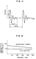
- arc start is effected by high frequency power and consequently, a high frequency voltage as shown in Fig. 11 is applied across the electrode and the base metal.
- radiation noise electric field intensity reaches up to about 70 dB ⁇ V as shown in Fig. 12. Accordingly, electric wave interference was caused which interfered with neighboring televisions, radios or electronic apparatus, giving rise to breakdown of them in an extreme case, or the high frequency was so intensive that the electrode surface was roughened to deteriorate the arc start characteristic.
- JP-A-56086679 describes an arc welding device in which two constant voltage dc power supplies are provided.
- the second dc power supply can provide a high voltage in order to start the arc.
- an arc welding machine and a plasma cutting machine each including a first power supply unit for supplying power across an electrode and a base metal, and a second DC power supply unit connected to a circuit fed by said first power supply unit to apply a high voltage across said electrode and said base metal during starting of the arc, characterized in that said second DC power supply unit is of the descending characteristic type and each of said machines comprises means for applying the high voltage from said second DC power supply unit across said electrode and said base metal during arc start and after generation of an arc, stopping the application of the high voltage from said second DC power supply unit to cause said first power supply unit to feed power.
- Fig. 1 shows a main circuit of an inconsumable electrode arc welding machine in which the first power supply unit 1 is a DC power supply.
- Fig. 2 shows a main circuit when the first power supply unit is an AC power supply.
- Fig. 3 shows a main circuit when the electrode in Fig. 1 is replaced with a consumable electrode.
- 1 to 7 designate the same components as those in the conventional example of Fig. 4.
- Reference numeral 11 designates a second DC power supply unit of a descending characteristic type which is adapted to apply a high voltage.
- Reference numeral 12 designates a rectifying element for blocking DC high voltage.
- the output of the second DC power supply unit is connected to a circuit fed by the first power supply unit, and the rectifying element 12, which blocks the application of high voltage to the first power supply unit in order that the high voltage output of the second DC power supply unit can be applied only across electrode 4 and base metal 3, is connected to and inserted in the circuit fed by the first power supply unit.
- the second DC power supply unit 11 is started through contact 7 and a DC high voltage of about 4KV for arc start is supplied across the electrode 4 and the base metal 3.
- DC power for formation of a stationary arc from first DC power supply unit 1 is supplied across the electrode 4 and the base metal 3.
- a gap between the electrode 4 and the base metal 3 is caused to undergo dielectric breakdown by the DC high voltage to thereby generate a corona discharge which in turn shifts to an arc.
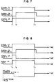
- the time for feeding power from the second DC power supply unit 11 begins with t1 at which the start switch 6 is operated and ends in t2 at which arc generation detector 5 is operated.
- Fig. 9 shows an operational characteristic which begins with arc start and proceeds thereafter. Power fed from the second DC power supply unit and having a descending characteristic is applied across the electrode 4 and the base metal 3 during no load, and after arc shift, power fed from the first power supply unit and having a descending characteristic or semi-constant voltage characteristic is applied.
- Fig. 2 shows the case where an AC power supply and a DC power supply which switches the polarity only when starting are used as the first power supply unit, and it can be understood easily that the same arc start mechanism as that in the case of Fig. 1 where the first power supply unit is the DC power supply prevails as will be seen from Fig. 6 when only the start phase is taken into account.
- Reference numeral 13 designates a unidirectional controllable rectifying element which is rendered to be conductive by receiving a signal from the arc generation detector 5 to supply power of electrode minus across the electrode 4 and the base metal 3. Similar effects could be obtained even when the welding load was replaced with cutting load in the embodiment.
- an embodiment of a consumable electrode arc welding machine shown in Fig. 3 will be described.
- a wire feed unit 10 is operated to feed a wire toward the base metal.
- a DC voltage of about 4KV fed from the second DC power supply unit is applied across wire 4 and base metal 3.
- Reference numeral 12 designates a rectifying element for blocking which permits the DC high voltage to be applied only across the wire and the base metal. Accordingly, as the wire is fed toward the base metal, a discharge is initiated when the distance between the wire tip and the base metal reaches about 2 mm and it shifts to a stationary arc because the first DC power supply unit is also in operation.
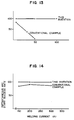
- the contactless start system of the present invention could completely eliminate the influence of slag adhesion to the wire tip and problems raised when the wire contacts the base metal, and results of an arc start test proved that the instantaneous arc start rate could be improved up to 100 % as shown in Fig. 14.
- a DC high voltage fed from the second DC power supply unit having the descending characteristic is applied across the electrode and the base metal upon arc start to cause a gap between the electrode and the base metal to undergo dielectric breakdown and trigger an arc following a corona discharge, thereby ensuring that arc start can be effected without contacting the electrode and the base metal.
- radiation noise during no load can be reduced.
- the arc start is carried out with the DC high voltage, leakage from an extension cable can be prevented and the arc start can be done steadily even when the length of the extension cable is made to be long.
- an arc welding machine of inconsumable electrode type and consumable electrode type
- a plasma cutting machine can be provided wherein radiation noise during no load can be eliminated and steady arc start can be ensured even with the extension cable prolonged.
Landscapes
- Engineering & Computer Science (AREA)
- Physics & Mathematics (AREA)
- Plasma & Fusion (AREA)
- Mechanical Engineering (AREA)
- Arc Welding Control (AREA)
Description
- • Electrode
- tungsten containing thorium, 2.4 mm ⊘
- • Argon gas
- 5 ℓ/min
- • Current
- 50 A
- • Distance between electrode and base metal
- 3 mm
- • The number of tests
- 100
- • Torch switch ON/OFF period
- 2-second ON/13-second OFF
| (Cur.) | (Volt.) | (Wire dia.) | (CO2 gas) | (Tip/base metal dist.) |
| 120 A | 19 V | 1.2 mm⊘ | 151/min | 15 mm |
| 200 A | 24 V | 1.2 mm⊘ | 151/min | 15 mm |
| 300 A | 32 V | 1.6 mm⊘ | 151/min | 20 mm |
- • The number of tests
- 100 for each case
- • Torch switch ON/OFF period
- 2-second ON/13-second OFF
- • Torch is vertical to base metal.
- Start is repeated with the torch stopped.
Claims (5)
- An arc welding machine and a plasma cutting machine each including a first power supply unit (1) for supplying power across an electrode (4) and a base metal (3), and a second DC power supply unit (11) connected to a circuit fed by said first power supply unit to apply a high voltage across said electrode and said base metal during starting of the arc,
characterized in that said second DC power supply unit (11) is of the descending characteristic type and each of said machines comprises means for applying the high voltage from said second DC power supply unit across said electrode (4) and said base metal (3) during arc start and after generation of an arc, stopping the application of the high voltage from said second DC power supply unit to cause said first power supply unit to feed power. - An arc welding machine and a plasma cutting machine according to claim 1,
characterized in that said applying means comprises arc generation detector means (5) for detecting generation of an arc by said first power supply unit, and switch means (7) responsive to a signal from said arc generation detector means to stop the operation of said second DC power supply unit (11). - An arc welding machine and a plasma cutting machine each including a first power supply unit (1) for supplying power across an electrode (4) and a base metal (3), and a second DC power supply source (11) of a descending characteristic type connected to a circuit fed by said first power supply unit to apply a high voltage across said electrode and said base metal,
characterized in that each of said machines comprises means for applying the high voltage from said second DC power supply unit across said electrode and said base metal during arc start and after generation of an arc, feeding power from said first power supply unit and said second DC power supply unit. - An arc welding machine and a plasma cutting machine according to claim 1 or 3,
characterized in that a rectifying element (12) or a unidirectional controllable rectifying element (13) is inserted in said circuit fed by said first power supply unit so that the high voltage output of said second DC power supply unit (11) may be applied across said electrode (4) and said base metal (3) at the same polarity as that of the output delivered out of said first power supply unit (1) during no load. - A arc welding machine according to claim 1 or 3,
characterized in that a rectifying element (12) or a unidirectional controllable rectifying element (13) is inserted in said circuit fed by said first DC power supply unit so that the high voltage output from said second DC power supply unit may be applied across a consumable electrode (4) and a base metal (3) at the same polarity as that of the output delivered out of said first DC power supply unit (1) during no load.
Applications Claiming Priority (4)
| Application Number | Priority Date | Filing Date | Title |
|---|---|---|---|
| JP225418/92 | 1992-08-25 | ||
| JP22541892A JP2631178B2 (en) | 1992-08-25 | 1992-08-25 | DC arc welding equipment and plasma cutting equipment |
| JP04340854A JP3076943B2 (en) | 1992-12-22 | 1992-12-22 | Arc welding equipment |
| JP340854/92 | 1992-12-22 |
Publications (2)
| Publication Number | Publication Date |
|---|---|
| EP0585068A1 EP0585068A1 (en) | 1994-03-02 |
| EP0585068B1 true EP0585068B1 (en) | 1998-04-15 |
Family
ID=26526628
Family Applications (1)
| Application Number | Title | Priority Date | Filing Date |
|---|---|---|---|
| EP93306602A Expired - Lifetime EP0585068B1 (en) | 1992-08-25 | 1993-08-20 | Arc welding machine and plasma cutting machine |
Country Status (4)
| Country | Link |
|---|---|
| US (2) | US5582751A (en) |
| EP (1) | EP0585068B1 (en) |
| CN (1) | CN1040301C (en) |
| DE (1) | DE69317961T2 (en) |
Families Citing this family (19)
| Publication number | Priority date | Publication date | Assignee | Title |
|---|---|---|---|---|
| JP3496031B2 (en) * | 1993-07-05 | 2004-02-09 | 株式会社フジキン | Ultra high purity gas supply system piping welding method |
| US5852278A (en) * | 1995-12-28 | 1998-12-22 | Matsushita Electric Industrial Co., Ltd. | Arc welding and arc plasma cutting machines having improved DC high-voltage generator |
| JP3078245B2 (en) * | 1997-08-06 | 2000-08-21 | 松下電器産業株式会社 | Arc start assist device |
| US6075224A (en) * | 1998-04-01 | 2000-06-13 | Illinois Tool Works Inc | Method of and apparatus for initiating a welding arc |
| US6034350A (en) * | 1998-04-01 | 2000-03-07 | Illinois Tool Works Inc. | Method and apparatus for initiating a welding arc using a background circuit |
| AT2774U1 (en) * | 1998-05-04 | 1999-04-26 | Inocon Technologie Gmbh | METHOD AND DEVICE FOR PARTLY MELTING OBJECTS |
| US6177651B1 (en) * | 1998-06-11 | 2001-01-23 | Illinois Tool Works Inc. | Method and apparatus for producing welding power |
| CN100361772C (en) * | 2000-11-13 | 2008-01-16 | 伊利诺斯器械工程公司 | Mechanical welding power source with starting circuit |
| US6388232B1 (en) * | 2000-11-27 | 2002-05-14 | Lincoln Global, Inc. | Starting and welding device for DC TIG welder and method of operating same |
| US6472634B1 (en) * | 2001-04-17 | 2002-10-29 | Lincoln Global, Inc. | Electric arc welding system |
| US6974932B2 (en) * | 2003-03-31 | 2005-12-13 | Illinois Tool Works Inc. | Method and apparatus for welding |
| US8476554B2 (en) * | 2005-06-01 | 2013-07-02 | Lincoln Global, Inc. | Methods and apparatus for improved low current AC/DC TIG welding and starting |
| WO2008051820A2 (en) * | 2006-10-20 | 2008-05-02 | Swagelok Company | Dc arc start with universal input |
| US8680431B2 (en) * | 2010-11-15 | 2014-03-25 | Lincoln Global, Inc. | Device and method to control a power source |
| US9839970B2 (en) * | 2010-12-21 | 2017-12-12 | Lincoln Global, Inc. | Dual wire welding system and method |
| US9463522B2 (en) * | 2012-04-05 | 2016-10-11 | GM Global Technology Operations LLC | Drawn arc welding |
| CN103331505B (en) * | 2013-07-12 | 2015-05-27 | 宣浩 | Electric spark bead welding circuit |
| EP3482862A1 (en) * | 2017-11-08 | 2019-05-15 | FRONIUS INTERNATIONAL GmbH | Method for contactless ignition of an arc and welding power source for carrying out an ignition method |
| CN108422069A (en) * | 2018-03-05 | 2018-08-21 | 唐山松下产业机器有限公司 | Reduce the method and system of welding machine arc noise |
Family Cites Families (14)
| Publication number | Priority date | Publication date | Assignee | Title |
|---|---|---|---|---|
| US2969494A (en) * | 1957-11-29 | 1961-01-24 | Gen Electric | Protective circuit for germanium and silicon rectifier cells |
| GB1069511A (en) * | 1962-08-01 | 1967-05-17 | British Welding Res Ass | Improvements relating to arcs |
| US3356928A (en) * | 1965-02-15 | 1967-12-05 | Int Rectifier Corp | Regulated rectifier for welding power supplies |
| GB1142206A (en) * | 1965-05-04 | 1969-02-05 | Welding Inst | Improvements in or relating to power sources for electric arc stabilisation |
| US3530359A (en) * | 1968-09-20 | 1970-09-22 | Miller Electric Mfg | Adjustable arc welding power supply system |
| US3637973A (en) * | 1969-02-19 | 1972-01-25 | Mitsubishi Electric Corp | Arc welding apparatus |
| US3818177A (en) * | 1972-09-05 | 1974-06-18 | Welding Inst | Arc welding |
| DE2740452A1 (en) * | 1977-09-08 | 1979-03-22 | Messer Griesheim Gmbh | WELDING POWER SOURCE FOR ARC WELDING WITH ALTERNATING CURRENT |
| JPS5686679A (en) * | 1979-12-17 | 1981-07-14 | Matsushita Electric Ind Co Ltd | Direct current arc welding machine |
| JPS59193763A (en) * | 1983-04-20 | 1984-11-02 | Hitachi Seiko Ltd | Dc arc welding power supply device |
| JPS6320631A (en) * | 1986-07-15 | 1988-01-28 | Nec Corp | Register selecting system |
| JPH026063A (en) * | 1988-06-17 | 1990-01-10 | Mitsubishi Electric Corp | Ac tig arc welding machine |
| US4950864A (en) * | 1989-02-17 | 1990-08-21 | The United States Of America As Represented By The United States Department Of Energy | DC arc weld starter |
| JPH06320631A (en) * | 1993-05-17 | 1994-11-22 | Toshiba Chem Corp | Voidless FRP manufacturing method |
-
1993
- 1993-08-20 EP EP93306602A patent/EP0585068B1/en not_active Expired - Lifetime
- 1993-08-20 DE DE69317961T patent/DE69317961T2/en not_active Expired - Lifetime
- 1993-08-25 CN CN93116583A patent/CN1040301C/en not_active Expired - Lifetime
-
1995
- 1995-02-21 US US08/391,095 patent/US5582751A/en not_active Expired - Lifetime
-
1996
- 1996-04-12 US US08/631,087 patent/US5773792A/en not_active Expired - Lifetime
Also Published As
| Publication number | Publication date |
|---|---|
| DE69317961D1 (en) | 1998-05-20 |
| DE69317961T2 (en) | 1998-09-10 |
| US5773792A (en) | 1998-06-30 |
| CN1040301C (en) | 1998-10-21 |
| CN1087043A (en) | 1994-05-25 |
| EP0585068A1 (en) | 1994-03-02 |
| US5582751A (en) | 1996-12-10 |
Similar Documents
| Publication | Publication Date | Title |
|---|---|---|
| US5773792A (en) | ARC welding machine and plasma cutting machine | |
| US6156999A (en) | Method and device for welding arc ignition for arc welding apparatus | |
| US3832513A (en) | Starting and stabilizing apparatus for a gas-tungsten arc welding system | |
| EP0436021B1 (en) | Plasma-arc cutting machine and a method of controlling the same | |
| US5225658A (en) | Stopping a plasma arc cutter upon completion of cutting | |
| US20050211685A1 (en) | Welding torch with plasma assist | |
| US3876855A (en) | Tungsten inert gas arc striking device | |
| US3174027A (en) | Pilot arc starting-arc working systems | |
| EP0007968B1 (en) | Improvements in methods and apparatus for electrical discharge machining | |
| US3309564A (en) | Arc welding apparatus having plasma generator for starting | |
| US3431390A (en) | Work-in-circuit arc starting apparatus | |
| US5643475A (en) | Power supply apparatus | |
| US4950864A (en) | DC arc weld starter | |
| US4418265A (en) | Device with high frequency contactless type arc generating mechanism | |
| US3551741A (en) | Arc striking or stabilization network having a detecting transformer and capacitor connected to the electrode | |
| JP3078150B2 (en) | DC arc welding machine and plasma cutting machine | |
| JP2768277B2 (en) | Arc welding machine and plasma cutting machine | |
| JPS5758977A (en) | Pulse arc welding machine | |
| US20250170665A1 (en) | Two-channel device for two-frequency arc welding | |
| CA1171143A (en) | Electrical welding device | |
| US20230321744A1 (en) | Device for arc welding and method of implementing the same | |
| JP3076943B2 (en) | Arc welding equipment | |
| US3646310A (en) | High-frequency starting device for an electric welding arc | |
| JPH036868B2 (en) | ||
| JPH0813416B2 (en) | Arc welding equipment |
Legal Events
| Date | Code | Title | Description |
|---|---|---|---|
| PUAI | Public reference made under article 153(3) epc to a published international application that has entered the european phase |
Free format text: ORIGINAL CODE: 0009012 |
|
| AK | Designated contracting states |
Kind code of ref document: A1 Designated state(s): DE FR GB IT |
|
| 17P | Request for examination filed |
Effective date: 19940420 |
|
| 17Q | First examination report despatched |
Effective date: 19960124 |
|
| GRAG | Despatch of communication of intention to grant |
Free format text: ORIGINAL CODE: EPIDOS AGRA |
|
| GRAG | Despatch of communication of intention to grant |
Free format text: ORIGINAL CODE: EPIDOS AGRA |
|
| GRAH | Despatch of communication of intention to grant a patent |
Free format text: ORIGINAL CODE: EPIDOS IGRA |
|
| GRAH | Despatch of communication of intention to grant a patent |
Free format text: ORIGINAL CODE: EPIDOS IGRA |
|
| GRAA | (expected) grant |
Free format text: ORIGINAL CODE: 0009210 |
|
| ITF | It: translation for a ep patent filed | ||
| AK | Designated contracting states |
Kind code of ref document: B1 Designated state(s): DE FR GB IT |
|
| REF | Corresponds to: |
Ref document number: 69317961 Country of ref document: DE Date of ref document: 19980520 |
|
| ET | Fr: translation filed | ||
| PLBE | No opposition filed within time limit |
Free format text: ORIGINAL CODE: 0009261 |
|
| STAA | Information on the status of an ep patent application or granted ep patent |
Free format text: STATUS: NO OPPOSITION FILED WITHIN TIME LIMIT |
|
| 26N | No opposition filed | ||
| REG | Reference to a national code |
Ref country code: GB Ref legal event code: IF02 |
|
| REG | Reference to a national code |
Ref country code: GB Ref legal event code: 746 Effective date: 20091215 |
|
| PGFP | Annual fee paid to national office [announced via postgrant information from national office to epo] |
Ref country code: GB Payment date: 20120815 Year of fee payment: 20 |
|
| PGFP | Annual fee paid to national office [announced via postgrant information from national office to epo] |
Ref country code: IT Payment date: 20120810 Year of fee payment: 20 Ref country code: DE Payment date: 20120816 Year of fee payment: 20 Ref country code: FR Payment date: 20120823 Year of fee payment: 20 |
|
| REG | Reference to a national code |
Ref country code: DE Ref legal event code: R071 Ref document number: 69317961 Country of ref document: DE |
|
| REG | Reference to a national code |
Ref country code: GB Ref legal event code: PE20 Expiry date: 20130819 |
|
| PG25 | Lapsed in a contracting state [announced via postgrant information from national office to epo] |
Ref country code: DE Free format text: LAPSE BECAUSE OF EXPIRATION OF PROTECTION Effective date: 20130821 |
|
| PG25 | Lapsed in a contracting state [announced via postgrant information from national office to epo] |
Ref country code: GB Free format text: LAPSE BECAUSE OF EXPIRATION OF PROTECTION Effective date: 20130819 |