EP0585037A1 - Zusammenbau einer Schubladenführung - Google Patents
Zusammenbau einer Schubladenführung Download PDFInfo
- Publication number
- EP0585037A1 EP0585037A1 EP93306493A EP93306493A EP0585037A1 EP 0585037 A1 EP0585037 A1 EP 0585037A1 EP 93306493 A EP93306493 A EP 93306493A EP 93306493 A EP93306493 A EP 93306493A EP 0585037 A1 EP0585037 A1 EP 0585037A1
- Authority
- EP
- European Patent Office
- Prior art keywords
- rail
- stop
- slide assembly
- inner rail
- intermediate rail
- Prior art date
- Legal status (The legal status is an assumption and is not a legal conclusion. Google has not performed a legal analysis and makes no representation as to the accuracy of the status listed.)
- Withdrawn
Links
- 230000027455 binding Effects 0.000 claims abstract description 5
- 230000000295 complement effect Effects 0.000 claims abstract description 4
- 230000001154 acute effect Effects 0.000 claims description 11
- 238000003780 insertion Methods 0.000 claims description 8
- 230000037431 insertion Effects 0.000 claims description 8
- 230000001419 dependent effect Effects 0.000 claims 3
- 230000007246 mechanism Effects 0.000 description 11
- 230000000712 assembly Effects 0.000 description 7
- 238000000429 assembly Methods 0.000 description 7
- 230000009471 action Effects 0.000 description 6
- 239000002184 metal Substances 0.000 description 4
- 238000012360 testing method Methods 0.000 description 3
- 230000006378 damage Effects 0.000 description 2
- 230000000994 depressogenic effect Effects 0.000 description 2
- 239000000463 material Substances 0.000 description 2
- 208000027418 Wounds and injury Diseases 0.000 description 1
- 238000013459 approach Methods 0.000 description 1
- 230000009286 beneficial effect Effects 0.000 description 1
- 230000008901 benefit Effects 0.000 description 1
- 230000002860 competitive effect Effects 0.000 description 1
- 238000010276 construction Methods 0.000 description 1
- 230000000881 depressing effect Effects 0.000 description 1
- 238000013461 design Methods 0.000 description 1
- 230000000694 effects Effects 0.000 description 1
- 230000006872 improvement Effects 0.000 description 1
- 208000014674 injury Diseases 0.000 description 1
- 230000014759 maintenance of location Effects 0.000 description 1
- 238000004519 manufacturing process Methods 0.000 description 1
- 238000012552 review Methods 0.000 description 1
Images


Classifications
-
- A—HUMAN NECESSITIES
- A47—FURNITURE; DOMESTIC ARTICLES OR APPLIANCES; COFFEE MILLS; SPICE MILLS; SUCTION CLEANERS IN GENERAL
- A47B—TABLES; DESKS; OFFICE FURNITURE; CABINETS; DRAWERS; GENERAL DETAILS OF FURNITURE
- A47B88/00—Drawers for tables, cabinets or like furniture; Guides for drawers
- A47B88/40—Sliding drawers; Slides or guides therefor
- A47B88/49—Sliding drawers; Slides or guides therefor with double extensible guides or parts
- A47B88/493—Sliding drawers; Slides or guides therefor with double extensible guides or parts with rollers, ball bearings, wheels, or the like
-
- A—HUMAN NECESSITIES
- A47—FURNITURE; DOMESTIC ARTICLES OR APPLIANCES; COFFEE MILLS; SPICE MILLS; SUCTION CLEANERS IN GENERAL
- A47B—TABLES; DESKS; OFFICE FURNITURE; CABINETS; DRAWERS; GENERAL DETAILS OF FURNITURE
- A47B88/00—Drawers for tables, cabinets or like furniture; Guides for drawers
- A47B88/40—Sliding drawers; Slides or guides therefor
- A47B88/423—Fastening devices for slides or guides
- A47B2088/4235—Fastening devices for slides or guides having a latch mechanism coupling or disconnecting a drawer with drawer side slide from the rest of the slide members
-
- A—HUMAN NECESSITIES
- A47—FURNITURE; DOMESTIC ARTICLES OR APPLIANCES; COFFEE MILLS; SPICE MILLS; SUCTION CLEANERS IN GENERAL
- A47B—TABLES; DESKS; OFFICE FURNITURE; CABINETS; DRAWERS; GENERAL DETAILS OF FURNITURE
- A47B2210/00—General construction of drawers, guides and guide devices
- A47B2210/0002—Guide construction for drawers
- A47B2210/0016—Telescopic drawer slide latch device
-
- A—HUMAN NECESSITIES
- A47—FURNITURE; DOMESTIC ARTICLES OR APPLIANCES; COFFEE MILLS; SPICE MILLS; SUCTION CLEANERS IN GENERAL
- A47B—TABLES; DESKS; OFFICE FURNITURE; CABINETS; DRAWERS; GENERAL DETAILS OF FURNITURE
- A47B2210/00—General construction of drawers, guides and guide devices
- A47B2210/0002—Guide construction for drawers
- A47B2210/0029—Guide bearing means
- A47B2210/0032—Balls
-
- A—HUMAN NECESSITIES
- A47—FURNITURE; DOMESTIC ARTICLES OR APPLIANCES; COFFEE MILLS; SPICE MILLS; SUCTION CLEANERS IN GENERAL
- A47B—TABLES; DESKS; OFFICE FURNITURE; CABINETS; DRAWERS; GENERAL DETAILS OF FURNITURE
- A47B2210/00—General construction of drawers, guides and guide devices
- A47B2210/0002—Guide construction for drawers
- A47B2210/0051—Guide position
- A47B2210/0059—Guide located at the side of the drawer
-
- A—HUMAN NECESSITIES
- A47—FURNITURE; DOMESTIC ARTICLES OR APPLIANCES; COFFEE MILLS; SPICE MILLS; SUCTION CLEANERS IN GENERAL
- A47B—TABLES; DESKS; OFFICE FURNITURE; CABINETS; DRAWERS; GENERAL DETAILS OF FURNITURE
- A47B2210/00—General construction of drawers, guides and guide devices
- A47B2210/0002—Guide construction for drawers
- A47B2210/0064—Guide sequencing or synchronisation
- A47B2210/0081—Telescopic drawer rails with stop blocks, e.g. synchronization buffers
Definitions
- the present invention relates to drawer slides, for example, to drawer slides incorporating stop assemblies.
- Drawer slides are necessary components in the manufacture of quality cabinets and furniture of various kinds. Some of the more demanding applications are found in the office furniture industry where the drawer slide function must satisfy the customers of the office furniture manufacturer.
- the most fundamental purpose of the drawer slide is to provide smooth and effortless movement of a drawer to which is attached, from a closed position to an open position. Sometimes this is accomplished by two channel members that slide in relation to each other, either by means of a roller or by means of ball bearing support.
- Stop lever assemblies are known that allow for competent stopping of the drawer at the end of its travel while providing convenient means for removal of the drawer once the stop is overcome.
- stop lever assembly utilizes a lever that is interior to the channel member that is affixed to the drawer to disengage a drawer from the slide assemblies. Normally, a central raised portion of the lever is able to contact a corresponding stop found on the opposing channel member. Thus, as the drawer is opened, it travels unimpeded until the stop lever engages the stop, thereafter preventing any further forward travel.
- One lever or one side is raised and the second lever of the second side is lowered. A subsequent improvement enabled the levers on both sides to be raised. However, these are ergonomically difficult to operate and they tend to stick and jam.
- stop lever utilizes an action that works in the same direction of travel as the drawer and the slide.
- the tab extends forward from the area of the stop and has a loop in the end for the user to engage. Once the loop is pulled forward for the desired distance, the stop is overcome and the drawer and channel can be removed from the cabinet.
- Other stop levers are known in the drawer slide industry, but they typically share much of the above-described approaches.
- the space allowed for stop lever mechanisms within the inner channel is extremely limited, since the entire rail assembly is only a short one-half inch in width. Thus, the usage of a mechanism is usually severely constrained by the design of the channel. At least in the vertical directions, the throw that a given tab or lever may have is determined by the clearance allowed within the inner channel.
- the lever that utilizes the line of travel action has a longer throw but requires the user to affirmatively engage the loop and pull it sufficiently forward. This action is clumsy and awkward and not as east for everyone to accomplish as the vertical action. It would be convenient to be able to simply push a stop release lever inwardly-laterally towards the drawer walls when releasing the slide. But the tiny clearance between the rails has, as far as is known, prevented an effective release of this type.
- the lever mechanism comprises a stop lever that is fixed to an inner channel member between the ends of the channel, and at one end of the stop lever, with the other end being free to resiliently flex from an at rest position to an actuated position.
- This stop lever preferably includes a lever trigger, and a middle portion having a block with stop faces.
- corresponding to the stop faces are faces found on opposing stop means of the other intermediate rail.
- orientated in lateral alignment with the lever trigger is a lever opening in the inner rail, that compatibly receives the lever tab as it is depressed into the opening.
- This opening does not necessarily have to be employed with a trigger that has a bridge forming configuration.
- the stop lever assembly of the present invention preferably allows the lever trigger to be actuated by simply depressing it in a lateral direction to thereby disengage the stops.
- Another preferred feature of the present invention is the affirmative angular engagement means provided by the stop lever block face and the opposing stop block face. Both the stop lever block face and the stop block face may be oriented at acute angles arranged in direct alignment when the drawer and inner channel member are advanced to the most forward position. The faces preferably engage at the most forward position and lock-up the two opposing parts.
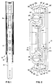
- the drawer rail assembly 10 in the illustrative form of the invention set forth as an exemplary embodiment, is shown to include an outer rail or channel 12, an intermediate rail or channel 16, and an inner rail or channel 14.
- the terms rail and channel are typically used in the trade interchangeably.
- the slide assemblies or simply “slides” as they are more commonly called, are arranged with their elongated axis horizontal, their smaller dimension being orientated vertically, and the thickness thereof being horizontal laterally.
- two such slide assemblies are employed, one on each side of a drawer or file, these being identical to each other except being in mirror image. For convenience, only one such slide assembly will be described in detail.
- outer rail 12 has a main vertical mounting panel or leg 12a, an upper generally horizontally extending leg 12b, and a lower generally horizontally extending leg 12c.
- legs 12b and 12c are arcuate radiused concave ball bearing receiving races or tracks 22 and 22' to receive the ball bearings 18 and 18' of the outer, lower and upper bearings.
- These ball bearings are in a series, axially spaced from each other by the retainers 20 and 20'.
- the upper and lower legs 12b and 12c also extend beyond the usual termination points 42b and 42c to include abutment extensions 50 and 50' each composed of intermediate sections 52 and 52' which are at an obtuse angle to the end of the arcuate portion, and terminal portions 54 and 54' which are at an obtuse angle to the intermediate sections 52 and 52'.
- abutment extensions 50 and 50' each composed of intermediate sections 52 and 52' which are at an obtuse angle to the end of the arcuate portion, and terminal portions 54 and 54' which are at an obtuse angle to the intermediate sections 52 and 52'.
- Intermediate rail 16 also includes a main vertically orientated panel or leg 16a, an upper generally horizontally extending leg 16b, and a lower generally horizontally extending leg 16c.
- Legs 16b and 16c have concave, radiused outer bearing tracks or races 24 and 24' on the lower and upper ends of the rail, respectively, and inner concave, radiused longitudinally extending tracks or races 32 and 32' on the lower and upper interfaces of legs 16b and 16c.
- These inner tracks receive inner, upper and lower bearings 28' and 28 which are secured in position by a single retainer 30 that extends between the two series of ball bearings.
- Inner track 14 has a generally vertically orientated mounted leg or panel 14a with a lower leg 14c extending generally transversely therefrom in a generally horizontal orientation, and an upper leg 14b doing likewise.
- the outer surfaces of these two legs define elongated, radiused, arcuate ball tracks or races 34 and 34' to engage the ball bearings 28 and 28' also.
- the inner rail has its generally C-shaped orientation opposite to the C-shaped orientation of the intermediate and outer rails.
- the outer rail will be mounted to a drawer or file of some type. However, this particular arrangement can be reversed with the inner rail mounted to the cabinet and the outer rail mounted to the drawer or other member to move relative to the cabinet.
- the outer rail 12 includes at its forward, axially outer end, a pair of vertically spaced openings 50 to receive the snap-in protrusions or lugs of the cabinet stop to be described more fully hereinafter. It also includes along its length a plurality of mounting openings 52 at spaced intervals for attachment to the inner wall of a cabinet or the like. These openings are positioned such that even when the inner rail is to be mounted in the cabinet, and the intermediate rail and inner rail are assembled but in an extended condition, access can be had to the outer rail openings through openings 16i in the intermediate rail.
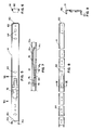
- a transversely extending vertically oriented tab or flange 54 which is received by the resilient inner cushion set forth in Figs. 22-25 and to be described hereinafter. This resilient cushion is engaged by the inner stop end of the inner rail when the drawer slide is fully closed as will be described hereinafter.
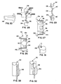
- the inner rail (Figs. 5-9) 14 has an outer axial end flange 60 with a resilient backing material thereon for engagement with the center stop as a secondary safety stop as to be described hereinafter.
- a plurality of openings 64 for mounting the rail to a drawer.
- openings are located at specific locations in the intermediate channel enabling access to the inner channel fastener when the slide assembly is either fully extended or fully retracted. Thus, access can be had by inserting a tool through openings e.g. 16n (Fig. 1) and into engagement with the mounting screws or other fasteners used.
- inner end of inner rail 14 is a pair of flanges 14d (Fig. 5) which slope toward each other and which engage the opposite, lower, and upper convex vertical ends of the inner cushion 120 in Figs. 22-25 in a manner to be described hereinafter, such that the interconnection formed holds the slide assembly closed until next activated.
- a stop tab 14c Adjacent these flanges, but spaced axially therefrom, is a stop tab 14c which strikes the front surface of the inner cushion when the assembly is closed, forming the first or primary stop.
- the stop lever 70 (Figs. 5 and 7). This stop lever is a polymeric, elongated element with its several portions being of one integral molded structure.
- a laterally protruding retention abutment 78 (Fig. 7) engages in a slot 14f behind the shoulder 14g of rail 14 to keep the stop lever in cooperative association mounted on inner rail 14 until it is to be purposely removed. Removal would be by depression of abutment 78 to force it out of engagement with shoulder 14g and thereby allow the lever to be slid back out of its snapped in relationship with tang 76 of rail 14.
- Rail 14 also preferably includes a window or opening 14h adjacent the terminal trigger portion 70a of lever 70 to provide more space for the trigger to be resiliently laterally depressed to thereby release the stop mechanism in a manner to be described.
- This trigger 70a also preferably includes a diagonally extending terminal or end portion 70b which is at an obtuse angle relative to portion 70a that generally is parallel to rail 14. End portion 70b therefore projects slightly toward the inner rail wall 14, and toward window 14h if one is used.
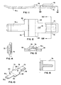
- An alternative stop lever is shown in Fig. 17. In this instance, no window or opening comparable to 14h is provided in rail 14.
- This trigger 70a is of resilient polymeric material with end portion 170b being able to engage with the wall 14a of rail 14 so that, upon further deformation of the trigger, it will be in effect be in abutment with rail 14 at both ends of the lever, like a bridge, such that further depression of the trigger will bias the abutment stop shoulders 80 out of engagement with the cooperative shoulders 90 of center stop 92.
- the face of these shoulders 90 is preferably at an acute angle relative to a plane perpendicular to the long axis of the slide, preferably an angle of about 15°.
- the stop shoulders 80 preferably are arranged as a pair of such shoulders astraddle the center of lever 70 as seen more specifically in Figs. 10 and 12.
- the shoulders are at the small acute angle preferably of about 15° but conceivably between 15° and about 45°, with the abutment shoulders and the center stop being complementary thereto, i.e., also being about the same but opposite angle, so as to result in a binding action between the two surfaces when they engage, even if under considerable force.
- Orientated toward the opposite end of the stop lever from the shoulders 80 is a pair of diagonal ramping surfaces 84 which cooperate with a similarly arranged pair of ramping shoulders 94 on lugs 90 for ease of assembly insertion of the inner rail into the intermediate rail. These ramp the stop with a temporary bias to allow passage of the stop surfaces.
- Cabinet stop 100 basically has a polymeric body extending the height of the outer rail, the body 102 having an upper transverse flange 104 and a lower transverse flange 106 which are positioned in the bearing races and against the upper and lower legs of the outer rail when assembled.
- the polymeric element is snap fitted into openings 50 (Fig. 3) of outer rail 12 with insertion of a pair of snap lugs 108 on the back face of body 102 (Fig. 21).
- a bearing protrusion 110 In the central portion of the front face is a bearing protrusion 110 which engages the offset central portion 16d (Fig.
- bearing protrusion 110 can have an orifice 112 therein matching an orifice 52 (Fig. 3) in the outer rail for insertion of a fastener.
- the edges 114 and 116 of flanges 104 and 106 serve as stop elements which are engaged by a pair of outwardly extending wings 134 and 136 of the center stop 92 (Figs. 26-31) to be described hereinafter, when the slide is closed or contracted.
- Figs. 22-25 is shown the resilient inner cushion 120 which is mounted on transverse flange or tab 54 (Fig. 3) of outer rail 12 at the inner end of this outer rail.
- This stop element is shown to be shaped somewhat like a figure 8, being vertically positioned in the orientation of the rail assembly depicted, and having an elongated central vertical slot 122 for receiving flange 54 as depicted in Fig. 16.
- the upper and lower ends of cushion 120 are preferably convexly curved, with the overall height dimension of this cushion being slightly greater than cooperative vertical spacing between the two flanges 14d at the inner end of inner rail 14 (Fig. 5).
- the center stop 92 is there depicted. As noted previously, this center stop had two stop shoulders 90 with diagonal inwardly orientated acute angle faces 90' on the inside face of the component 92. On the rear face are three protruding snap-in lugs or protrusions 136 and 138 which form a snap fit with corresponding openings at the outer end of the intermediate rail. On the outer end of element 92 is the pair of wings 134 serving as stop surfaces when engaging the outer end 114 of cabinet stop 100 (Fig. 19) when the intermediate rail is fully closed into the outer rail. This polymeric member also serves as a resilient bushing have lubricious properties, for preventing rail to rail metal contact of the inner rail to the intermediate rail if the slide assembly is torsionally twisted.
- element 92 On the opposite inner end of element 92 is a pair of special tapered, resilient, projecting fingers 140 (Figs. 26 and 30) integral with the element, spaced from and parallel to each other, and spaced from the outermost plane of element 92 to overlap the metallic bearing retainer 30 in a position of the retainer adjacent the center stop.
- the inner rail By extending slightly over the edge of the bearing retainer, this is beneficial when the inner rail is inserted longitudinally into engagement with the intermediate rail. Specifically, the inner rail will be guided by the fingers over the bearing retainer to prevent the inner end of the inner rail from engaging the end of the bearing retainer so that the latter will not be axially shifted by the end of the inner rail to cause difficulty of assembly. Rather, the inner end of the inner rail slides over the fingers, which also help to retain the bearing retainer, and into engagement with the ball bearings themselves, for optimum interengagement insertion.
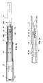
- the inner end of element 92 also serves to limit actual movement of the outer axial end of the bearing retainer 30 (Fig. 2).
- the inner axial end of movement the bearing retainer 30 is limited by the collector or collectors tabs 16t (Fig. 16).
- collectors 16t are specially located relative to the outer end of the intermediate rail such that optimum positioning of the rail members occurs with respect to each other. That is, these inner collector tabs are so located so that ball retainer 30 does not strike center stop 92 at full extension, under normal conditions.
- the retainer moves at one-half the speed and one-half the distance of the inner rail when extended, with proper placement of collector tabs 16t, that is, greater than the length of retainer 30 plus one-half of the travel distance of rail 14 relative to rail 16, the retainer will not normally strike but will stop closely adjacent to but short of center stop 92. If, however, stop lever 70 is actuated to receive rail 14 from slide assembly 10, movement of retainer 30 will be restrained by center stop 92.
- this entire assembly is composed of components that require no riveting, forming or staking of the metal, but rather, can be assembled or disassembled easily and quickly, even without tools. Thus, even if some of the components should become worn, for example, they can be readily removed and replaced, without tools, in a matter of seconds.
- the slide assembly can be mounted in a cabinet or the like and subsequently adjusted at full extension without removing the drawer. It has direct access openings or windows through the intermediate rail and the center member to allow an installer to insert the mounting screws into rail 14 without removing rail 14 from the slide assembly. The openings extend clear through the structure and all of its components for mounting when it is in contracted or closed condition.
- the lead-in ramps on both the drawer i.e., the inner rail and the outer cabinet rail allow for fast self-alignment when inserting the drawers. This is significant because the drawer is often inserted without being able to see the components interengaging.
Landscapes
- Drawers Of Furniture (AREA)
Applications Claiming Priority (2)
| Application Number | Priority Date | Filing Date | Title |
|---|---|---|---|
| US07/934,423 US5316389A (en) | 1992-08-24 | 1992-08-24 | Drawer slide assembly |
| US934423 | 1997-09-19 |
Publications (1)
| Publication Number | Publication Date |
|---|---|
| EP0585037A1 true EP0585037A1 (de) | 1994-03-02 |
Family
ID=25465546
Family Applications (1)
| Application Number | Title | Priority Date | Filing Date |
|---|---|---|---|
| EP93306493A Withdrawn EP0585037A1 (de) | 1992-08-24 | 1993-08-17 | Zusammenbau einer Schubladenführung |
Country Status (4)
| Country | Link |
|---|---|
| US (1) | US5316389A (de) |
| EP (1) | EP0585037A1 (de) |
| JP (2) | JPH0739430A (de) |
| CA (1) | CA2104200C (de) |
Cited By (9)
| Publication number | Priority date | Publication date | Assignee | Title |
|---|---|---|---|---|
| US5542759A (en) * | 1995-04-27 | 1996-08-06 | Snap-On Technologies, Inc. | Shock absorbing disconnect latch for drawer slides |
| US5851059A (en) * | 1997-03-04 | 1998-12-22 | Jonathan Manufacturing Corporation | Two-way extended travel slide suspension |
| US5951132A (en) * | 1997-11-18 | 1999-09-14 | Jonathan Manufacturing Corp. | Multi-use snap-part body for slider |
| US6145945A (en) * | 1998-11-12 | 2000-11-14 | Accuride International, Inc. | Drawer slide bearing retainer and guide block |
| US6938967B2 (en) * | 2001-12-12 | 2005-09-06 | Pentair Electronic Packaging Co. | Telescoping slide assembly |
| ES2288343A1 (es) * | 2005-02-04 | 2008-01-01 | Ezkanda, S.A. | Anclaje entre las guias de un cajon o similar y los carriles que las sostienen. |
| CN100515272C (zh) * | 2004-07-23 | 2009-07-22 | 川湖科技股份有限公司 | 滑轨的缓冲定位装置 |
| CN101589889B (zh) * | 2008-05-26 | 2011-09-21 | 川湖科技股份有限公司 | 滑轨收合的定位装置 |
| CN112890473A (zh) * | 2019-11-19 | 2021-06-04 | Topsco有限公司 | 保持器恢复正确位置的抽屉用滑动装置 |
Families Citing this family (43)
| Publication number | Priority date | Publication date | Assignee | Title |
|---|---|---|---|---|
| US5507571A (en) * | 1992-08-20 | 1996-04-16 | Knape & Vogt Manufacturing Company | Drawer slide assembly |
| US5626406A (en) * | 1995-02-02 | 1997-05-06 | Glenayre Electronics, Inc. | Integrated chassis slide assembly |
| US5577821A (en) * | 1995-03-24 | 1996-11-26 | Chu; Leo | Sliding track assembly for drawers |
| US5757109A (en) * | 1997-02-07 | 1998-05-26 | Accuride International, Inc. | Telescopic drawer slide with soft sequencing latch |
| US5980007A (en) * | 1997-04-23 | 1999-11-09 | Accuride International, Inc. | Drawer slide undermount bracket with flexible locking tab |
| US6238031B1 (en) | 2000-02-24 | 2001-05-29 | Kuo-Chan Weng | Sliding track assembly for drawers |
| US6220683B1 (en) * | 2000-06-13 | 2001-04-24 | Yin Da Slide Co., Ltd. | Sliding track assembley for drawer |
| US6435636B1 (en) | 2000-06-15 | 2002-08-20 | Compx International Inc. | Drawer slide cushion end stop bumper construction |
| US6817685B2 (en) | 2000-08-08 | 2004-11-16 | Accuride International Inc. | Release mechanism for drawer slide latches |
| CN1232204C (zh) * | 2000-11-16 | 2005-12-21 | 艾库里德国际有限公司 | 抽屉摩擦滑轨 |
| US6554379B2 (en) * | 2001-02-16 | 2003-04-29 | Central Industrial Supply Company, Inc. | Slide rail assembly with front release |
| WO2003015581A1 (en) * | 2001-08-17 | 2003-02-27 | Accuride International, Inc. | Guide tab and slide incorporating the same |
| US6585335B2 (en) * | 2001-09-28 | 2003-07-01 | King Slide Works Co., Ltd. | Rear-section bolt lock structure of a slide |
| TWI233342B (en) * | 2001-10-12 | 2005-06-01 | Accuride Int Inc | Three member thin drawer slide |
| US6601713B2 (en) * | 2001-12-10 | 2003-08-05 | Hewlett-Packard Development Company, L.P. | Rack assembly that does not require tools for coupling slides together |
| US6883885B2 (en) * | 2001-12-19 | 2005-04-26 | Jonathan Manufacturing Corporation | Front release for a slide assembly |
| TW566127U (en) * | 2002-05-10 | 2003-12-11 | King Slide Works Co Ltd | Positioning track assembly for drawer |
| WO2004107912A2 (en) * | 2003-05-30 | 2004-12-16 | Central Industrial Supply Company (A Texas Corporation) | Cam lock with torsion spring for a drawer slide |
| US7604307B2 (en) * | 2003-10-24 | 2009-10-20 | General Devices Co., Inc. | Telescoping slide assembly with quick-mount keyhole lock system |
| GB2410678B (en) * | 2004-02-09 | 2007-01-31 | King Slide Works Co Ltd | Positioning device for a multi-section slide track assembly of drawers |
| CA2537691A1 (en) * | 2005-02-23 | 2006-08-23 | Logimex Inc. | Drawer slide assembly with catch mechanism |
| USD554485S1 (en) * | 2005-12-13 | 2007-11-06 | Pentair Electronic Packaging Co. | Heavy duty telescoping slide hardware |
| USD562117S1 (en) * | 2005-12-13 | 2008-02-19 | Pentair Electronic Packaging Co. | Heavy duty telescoping slide hardware |
| TWM295704U (en) * | 2006-01-06 | 2006-08-11 | Jarllytec Co Ltd | Alignment mechanism for sliding track |
| WO2008067534A2 (en) * | 2006-11-30 | 2008-06-05 | Waterloo Industries, Inc. | Drawer slide |
| DE102006061096A1 (de) * | 2006-12-22 | 2008-06-26 | BSH Bosch und Siemens Hausgeräte GmbH | Teleskopauszug |
| DE202009001962U1 (de) * | 2008-11-03 | 2010-04-01 | Paul Hettich Gmbh & Co. Kg | Auszugsführung |
| TWI392465B (zh) * | 2008-11-20 | 2013-04-11 | King Slide Works Co Ltd | 用於滑軌組件之自動回歸裝置 |
| TWI421047B (zh) * | 2011-07-27 | 2014-01-01 | King Slide Works Co Ltd | 滑軌總成的安裝構造 |
| DE102012000551B4 (de) * | 2012-01-11 | 2014-12-31 | SSI Schäfer PEEM GmbH | Gleitführung für ein Lastaufnahmemittel |
| USD695599S1 (en) | 2012-05-31 | 2013-12-17 | Actron Manufacturing, Inc. | Drawer slide closing mechanism |
| US8919897B2 (en) | 2013-05-03 | 2014-12-30 | King Slide Works Co., Ltd. | Slide assembly with deceleration device |
| US9211008B2 (en) * | 2014-01-22 | 2015-12-15 | King Slide Works Co., Ltd. | Slide assembly |
| DE202015106016U1 (de) * | 2015-11-09 | 2017-02-13 | Accuride International Gmbh | Crash-Verriegelung |
| US10485132B2 (en) * | 2016-05-27 | 2019-11-19 | Hewlett Packard Enterprise Development Lp | Rail kits |
| KR20190085332A (ko) * | 2018-01-10 | 2019-07-18 | (주)세고스 | 서랍용 슬라이드 장치 |
| US10372170B1 (en) * | 2018-05-20 | 2019-08-06 | Kunshan Lemtech Slide Technology Co., Ltd. | Linear sliding structure of laptop keyboard and cover case |
| CN111132495B (zh) * | 2018-10-30 | 2021-09-10 | 川湖科技股份有限公司 | 滑轨总成 |
| KR102377274B1 (ko) * | 2020-02-25 | 2022-03-23 | (주)세고스 | 락킹기능을 갖는 가이드레일 |
| CN112535364A (zh) * | 2020-12-09 | 2021-03-23 | 海宁市启程智能装备有限公司 | 抽屉导轨中的滑轨底座 |
| CA3230377A1 (en) | 2021-08-30 | 2023-03-09 | Hubbell Incorporated | Low profile outdoor pedestal |
| USD1053697S1 (en) * | 2023-04-13 | 2024-12-10 | Nan Juen International Co., Ltd. | Slide rail fastener |
| US12495902B2 (en) * | 2023-09-21 | 2025-12-16 | Nan Juen International Co., Ltd. | Sliding rail assembly |
Citations (3)
| Publication number | Priority date | Publication date | Assignee | Title |
|---|---|---|---|---|
| US3588198A (en) * | 1969-08-15 | 1971-06-28 | Lyon Metal Products Inc | Suspension system for filing cabinet |
| AT372830B (de) * | 1981-11-02 | 1983-11-25 | Fulterer Gmbh | Schubladenauszugeinrichtung in teleskopbauart |
| US4423914A (en) * | 1981-05-18 | 1984-01-03 | Knape & Vogt Manufacturing Co. | Drawer slide locking lever |
Family Cites Families (25)
| Publication number | Priority date | Publication date | Assignee | Title |
|---|---|---|---|---|
| US2277702A (en) * | 1940-12-14 | 1942-03-31 | Kennedy Mfg Company | Slide suspension |
| US2277703A (en) * | 1941-05-02 | 1942-03-31 | Kennedy Mfg Company | Drawer slide |
| US2859070A (en) * | 1954-05-21 | 1958-11-04 | Mc Graw Edison Co | Extension hanger for cabinet drawer |
| US2981584A (en) * | 1957-12-31 | 1961-04-25 | Friend Irvin | Drawer and track construction |
| US3092429A (en) * | 1960-05-23 | 1963-06-04 | David Ind | Chassis slide mechanism |
| US3142517A (en) * | 1960-09-28 | 1964-07-28 | Charles D Ward | Drawer suspension means |
| US3141714A (en) * | 1961-06-23 | 1964-07-21 | Jonathan Mfg Company | Rear lock stop mechanism |
| US3123419A (en) * | 1961-08-23 | 1964-03-03 | Lock for drawer assemblies | |
| US3243247A (en) * | 1964-02-24 | 1966-03-29 | Knape & Vogt Mfg Co | Self-closing drawer slide |
| US3259447A (en) * | 1964-04-01 | 1966-07-05 | Addressograph Multigraph | Drawer stop |
| US3278250A (en) * | 1965-03-04 | 1966-10-11 | Knape & Vogt Mfg Co | Drawer rail assembly |
| US3589778A (en) * | 1970-02-24 | 1971-06-29 | Huot Mfg Co | Cabinet drawer slide assembly |
| US3782800A (en) * | 1972-06-22 | 1974-01-01 | Stanley Works | Latch mechanism |
| US3954315A (en) * | 1975-02-26 | 1976-05-04 | Sanden Edwin H | Cabinet drawer |
| US3937531A (en) * | 1975-03-03 | 1976-02-10 | Hagen Magnus F | Telescoping drawer slide section for 2-member telescopic ball bearing slides affording full extension |
| US3995927A (en) * | 1976-02-02 | 1976-12-07 | Hardware Designers, Inc. | Front release drawer slide |
| US4274689A (en) * | 1979-09-10 | 1981-06-23 | Leslie Metal Arts Company | Drawer glide assembly |
| US4473262A (en) * | 1982-01-11 | 1984-09-25 | Jacmorr Manufacturing Limited | Latching device for latching a drawer to a drawer slide |
| US4441772A (en) * | 1982-02-11 | 1984-04-10 | Hardware Designers, Inc. | Separable bottom mounted drawer slide |
| US4560212A (en) * | 1983-10-07 | 1985-12-24 | Standard Precision, Inc. | Three part ball bearing slide with lockable intermediate slide member |
| US4662761A (en) * | 1986-08-18 | 1987-05-05 | Knape & Vogt Manufacturing Company | Sequential drawer slide |
| US4765669A (en) * | 1987-06-03 | 1988-08-23 | Ford Motor Company | Adaptable robotic gripper assembly |
| US5085523A (en) * | 1989-08-07 | 1992-02-04 | General Devices Co., Inc. | Slide release mechanism |
| US4998828A (en) * | 1989-10-02 | 1991-03-12 | General Devices Co., Inc. | Over and under telescoping slide assembly |
| US5255983A (en) * | 1992-07-28 | 1993-10-26 | Accuride International, Inc. | Shock absorbing disconnect latch for ball bearing slides |
-
1992
- 1992-08-24 US US07/934,423 patent/US5316389A/en not_active Expired - Lifetime
-
1993
- 1993-08-16 CA CA002104200A patent/CA2104200C/en not_active Expired - Lifetime
- 1993-08-17 EP EP93306493A patent/EP0585037A1/de not_active Withdrawn
- 1993-08-19 JP JP23751493A patent/JPH0739430A/ja active Pending
-
2000
- 2000-08-18 JP JP2000248965A patent/JP2001078844A/ja not_active Withdrawn
Patent Citations (3)
| Publication number | Priority date | Publication date | Assignee | Title |
|---|---|---|---|---|
| US3588198A (en) * | 1969-08-15 | 1971-06-28 | Lyon Metal Products Inc | Suspension system for filing cabinet |
| US4423914A (en) * | 1981-05-18 | 1984-01-03 | Knape & Vogt Manufacturing Co. | Drawer slide locking lever |
| AT372830B (de) * | 1981-11-02 | 1983-11-25 | Fulterer Gmbh | Schubladenauszugeinrichtung in teleskopbauart |
Cited By (13)
| Publication number | Priority date | Publication date | Assignee | Title |
|---|---|---|---|---|
| US5542759A (en) * | 1995-04-27 | 1996-08-06 | Snap-On Technologies, Inc. | Shock absorbing disconnect latch for drawer slides |
| US5851059A (en) * | 1997-03-04 | 1998-12-22 | Jonathan Manufacturing Corporation | Two-way extended travel slide suspension |
| US5951132A (en) * | 1997-11-18 | 1999-09-14 | Jonathan Manufacturing Corp. | Multi-use snap-part body for slider |
| US6224178B1 (en) | 1997-11-18 | 2001-05-01 | Jonathan Manufacturing Corporation | Multi-use snap-part body for slider |
| US6145945A (en) * | 1998-11-12 | 2000-11-14 | Accuride International, Inc. | Drawer slide bearing retainer and guide block |
| US6254210B1 (en) * | 1998-11-12 | 2001-07-03 | Accuride International, Inc | Drawer slide bearing retainer and guide block |
| US6938967B2 (en) * | 2001-12-12 | 2005-09-06 | Pentair Electronic Packaging Co. | Telescoping slide assembly |
| CN100515272C (zh) * | 2004-07-23 | 2009-07-22 | 川湖科技股份有限公司 | 滑轨的缓冲定位装置 |
| ES2288343A1 (es) * | 2005-02-04 | 2008-01-01 | Ezkanda, S.A. | Anclaje entre las guias de un cajon o similar y los carriles que las sostienen. |
| ES2288343B1 (es) * | 2005-02-04 | 2008-12-01 | Ezkanda, S.A. | Anclaje entre las guias de un cajon o similar y los carriles que las sostienen. |
| CN101589889B (zh) * | 2008-05-26 | 2011-09-21 | 川湖科技股份有限公司 | 滑轨收合的定位装置 |
| CN112890473A (zh) * | 2019-11-19 | 2021-06-04 | Topsco有限公司 | 保持器恢复正确位置的抽屉用滑动装置 |
| CN112890473B (zh) * | 2019-11-19 | 2022-07-12 | Topsco有限公司 | 保持器恢复正确位置的抽屉用滑动装置 |
Also Published As
| Publication number | Publication date |
|---|---|
| CA2104200A1 (en) | 1994-02-22 |
| CA2104200C (en) | 2004-06-22 |
| US5316389A (en) | 1994-05-31 |
| JPH0739430A (ja) | 1995-02-10 |
| JP2001078844A (ja) | 2001-03-27 |
Similar Documents
| Publication | Publication Date | Title |
|---|---|---|
| CA2104200C (en) | Drawer slide assembly | |
| US5411333A (en) | Recyclable drawer slide | |
| CA1170702A (en) | Drawer slide locking lever | |
| US6805418B2 (en) | Friction drawer slide | |
| EP0581499B1 (de) | Stossdämpfende Entriegelungsvorrichtung für kugelgelagerte Führungen | |
| US5951132A (en) | Multi-use snap-part body for slider | |
| US5542759A (en) | Shock absorbing disconnect latch for drawer slides | |
| EP0578905B1 (de) | Vollauszug für Schubladen | |
| US6883885B2 (en) | Front release for a slide assembly | |
| EP1550385B1 (de) | Vorrichtung zur Höhenverstellung einer Schublade | |
| EP1416828B1 (de) | Gleitschiene mit führungszapfen | |
| US5868479A (en) | Drawer slide assembly | |
| EP0542946B1 (de) | Zerlegbares schloss | |
| EP1130985B1 (de) | Schubladenführung mit schwebendem anschlag | |
| EP0429872B1 (de) | Lösbare Riegelvorrichtung für Auszugsführung | |
| US4252382A (en) | Drawer slide | |
| EP0743031A2 (de) | Schubkastenauszugsführung | |
| US6729703B2 (en) | Snap-in latch | |
| US6499819B2 (en) | Drawer slide | |
| US20060186773A1 (en) | Drawer guide rail assembly | |
| EP0843064B1 (de) | Beschlag für ein Fenster | |
| EP0037257A1 (de) | Schubladenzusammenfügung | |
| CA1118031A (en) | Drawers and drawer components | |
| DE10003379C2 (de) | Abschirm- und/oder Schutzvorrichtung für eine Wandöffnung an einem Gebäude, insbesondere für ein Fenster | |
| GB1604816A (en) | Drawers and drawer components |
Legal Events
| Date | Code | Title | Description |
|---|---|---|---|
| PUAI | Public reference made under article 153(3) epc to a published international application that has entered the european phase |
Free format text: ORIGINAL CODE: 0009012 |
|
| AK | Designated contracting states |
Kind code of ref document: A1 Designated state(s): AT DE GB |
|
| 17P | Request for examination filed |
Effective date: 19940831 |
|
| 17Q | First examination report despatched |
Effective date: 19950505 |
|
| GRAH | Despatch of communication of intention to grant a patent |
Free format text: ORIGINAL CODE: EPIDOS IGRA |
|
| STAA | Information on the status of an ep patent application or granted ep patent |
Free format text: STATUS: THE APPLICATION IS DEEMED TO BE WITHDRAWN |
|
| 18D | Application deemed to be withdrawn |
Effective date: 19960611 |