EP0584841B1 - Methods and apparatus for fusing armature or stator wires - Google Patents
Methods and apparatus for fusing armature or stator wires Download PDFInfo
- Publication number
- EP0584841B1 EP0584841B1 EP93117137A EP93117137A EP0584841B1 EP 0584841 B1 EP0584841 B1 EP 0584841B1 EP 93117137 A EP93117137 A EP 93117137A EP 93117137 A EP93117137 A EP 93117137A EP 0584841 B1 EP0584841 B1 EP 0584841B1
- Authority
- EP
- European Patent Office
- Prior art keywords
- electrode
- section
- displacement
- force
- predetermined
- Prior art date
- Legal status (The legal status is an assumption and is not a legal conclusion. Google has not performed a legal analysis and makes no representation as to the accuracy of the status listed.)
- Expired - Lifetime
Links
Images


Classifications
-
- B—PERFORMING OPERATIONS; TRANSPORTING
- B23—MACHINE TOOLS; METAL-WORKING NOT OTHERWISE PROVIDED FOR
- B23K—SOLDERING OR UNSOLDERING; WELDING; CLADDING OR PLATING BY SOLDERING OR WELDING; CUTTING BY APPLYING HEAT LOCALLY, e.g. FLAME CUTTING; WORKING BY LASER BEAM
- B23K11/00—Resistance welding; Severing by resistance heating
- B23K11/24—Electric supply or control circuits therefor
- B23K11/25—Monitoring devices
- B23K11/252—Monitoring devices using digital means
- B23K11/255—Monitoring devices using digital means the measured parameter being a force
-
- H—ELECTRICITY
- H01—ELECTRIC ELEMENTS
- H01R—ELECTRICALLY-CONDUCTIVE CONNECTIONS; STRUCTURAL ASSOCIATIONS OF A PLURALITY OF MUTUALLY-INSULATED ELECTRICAL CONNECTING ELEMENTS; COUPLING DEVICES; CURRENT COLLECTORS
- H01R39/00—Rotary current collectors, distributors or interrupters
- H01R39/02—Details for dynamo electric machines
- H01R39/32—Connections of conductor to commutator segment
-
- H—ELECTRICITY
- H02—GENERATION; CONVERSION OR DISTRIBUTION OF ELECTRIC POWER
- H02K—DYNAMO-ELECTRIC MACHINES
- H02K15/00—Methods or apparatus specially adapted for manufacturing, assembling, maintaining or repairing of dynamo-electric machines
- H02K15/0056—Manufacturing winding connections
- H02K15/0068—Connecting winding sections; Forming leads; Connecting leads to terminals
Abstract
Description
- The present invention relates to a fusing apparatus and method for connecting a lead wire to an electrically conductive section of an armature or a stator, and, more particularly, to machines for fusing the armature wires of an electric motor to a hook member ("tang") or slot of a commutator bar and for fusing wires to stator hooks.
- Although fusing machines are widely used, a system for precisely controlling the fusing operation is not yet available. Prior attempts to control the fusing operation have involved the period during which electric current is applied to a workpiece. However, simple timing mechanisms do not provide any feedback to the fusing machine for quality control. Other fusing machines monitor the temperature of the joint being fused with fiber optics. Temperature monitors do not indicate either electrode pressure or electrode displacement, and therefore cannot determine whether the electrode is properly deforming and fusing the armature wire and commutator.
- US Patent No. 4,371,772 describes a fusing machine having a spring assembly system. A shaft moves downward to cause an electrode to contact a commutator hook. The downward movement of the shaft causes the hook to bend and compresses a spring in the fusing machine. The shaft reaches a stop, and electric current is applied. Additional force is applied by the electrode to further deform the hook and the wire to create the cohesion joint. The magnitude of the additional force will depend on the previous spring compression, the remaining spring release, and the physical properties of the spring.
- Even slight variations in the resistance encountered by the electrode will alter the amount of the spring compression in the prior art system. Such variations may be caused, for example, by changes in the hook geometry, the number of wires under a hook, or variations in hook materials and wire sizes. This makes it difficult to ensure that current is applied to the electrode when there is maximum surface contact between the electrode and the hook (as required for proper operation). Successive fusing operations also depend on these variable factors, making it difficult to maintain consistency and quality control. Whenever the fusing conditions change, laborious adjustments are required to guaranty ideal current supply position and electrode force application.
- The mechanical resistance of a fusion or "cohesion" joint depends on the final pressure applied. Variations in the electrode position (hook deformation) alter the heating rates and the maximum temperatures of the parts. The heating rates and maximum temperatures influence wire insulation removal, electrode wear, and the final quality of the cohesion joint.
- "Fusing Automation for Electric Motor Production" by Allan Warner, published in "Coil Winding 88" discloses another fusing machine in which electrode force is generated by a spring. Monitoring of the total displacement of the fusing electrode during fusing is employed as a measure of the acceptability of the fused joint.
- It would be desirable to provide a fusing machine which applies electrode force in a consistent manner, tailored to the physical characteristics of the workpiece, and independent of spring compression characteristics. It would also be desirable that such a machine be able to adjust for varying fusing conditions easily and quickly.
- In view of the foregoing, it is an object of this invention to provide a fusing machine that adjusts electrode displacement according to a predetermined function.
- These and other objects are achieved in preferred embodiments of the invention, which in one general aspect provides fusing apparatus for connecting a lead wire to an electrically conductive section of an armature or a stator comprising an electrode to contact said section and to apply electric current to heat said section and the lead wire in thermal contact with said electrode, means for moving said electrode to deform said section around said lead wire by applying force onto said section, means for monitoring relative displacement occurring between said electrode and said section, and characterised by means responsive to said means for monitoring for controlling said means for moving in order to cause the relative displacement of said electrode and said section to conform to a predetermined displacement function.
- In another general aspect the invention provides a fusing method for connecting a lead wire to an electrically conductive section of an armature or a stator, wherein said method comprises contacting by means of an electrode said section to apply electric current to heat said section and the lead wire in thermal contact with said electrode, moving said electrode to deform said section around said lead wire by applying force onto said section, monitoring relative displacement between said electrode and said section, and characterised by controlling movement of said electrode responsive to said monitoring step to cause the relative displacement between said electrode and said section to conform to a predetermined displacement function.
- Other preferred but optional features are as set out in the subordinate claims.
- One embodiment of the invention provides a fusing machine having a threaded sleeve for converting the rotary motion of a screw mechanism to a precise translation of the electrode in the electrode axis. The threaded sleeve and screw mechanism permits precise placement of the electrode in contact with the commutator hook or slot. Using the threaded sleeve and screw mechanism, the electrode can be consistently displaced for each fusing operation.
- The fusing machine may include a load cell for measuring electrode pressure, and an encoder for accurately determining the electrode displacement. A microprocessor-based control system may be used, which receives pressure and displacement data from the load cell and encoder, respectively, and acts on a motor to modify those quantities.
- The microprocessor stores a distinct, predetermined electrode displacement function with displacement as a function of time, X(t), or displacement as a function of force, X(p), for each hook or slot variation that the apparatus can process. Electrode position may be continuously measured and adjusted according to the displacement function. The apparatus applies current to the electrode when the electrode is in a predetermined displacement range, and terminates fusing when the electrode is in a second predetermined displacement range. This process is particularly well suited for fusing small diameter wires.
- The microprocessor may also store a distinct, predetermined electrode force function with force as a function of displacement, P(x), or force as a function of time, P(t), for each hook or slot variation that the apparatus can process. The force exerted by the electrode on the workpiece may be continuously measured by a force transducer, eg. a load cell, and adjusted according to the force function. The microprocessor control circuit acts on the motor to apply electrode force as a function of electrode displacement.
- Controlling the means for moving the electrode, in order to cause the force to substantially conform to a predetermined force function, is the subject matter of the present applicant's EP-B-0419849 (application 90116084.6, from which the present application is divided).
- The above and other objects and advantages of the invention will be apparent upon consideration of the following detailed description, taken in conjunction with the accompanying drawings, in which like reference numerals refer to like parts throughout, and in which:
- Figs. 1 - 4 are partial elevational views of an electrode fusing a commutator hook and armature wire to a commutator bar;
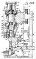
- Fig. 5 is a cross-sectional view of an illustrative embodiment of a fusing machine constructed in accordance with the principles of this invention;
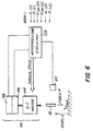
- Fig. 6 is a schematic diagram of the feedback loop control system of this invention which can be used in the fusing machine of Fig. 5;
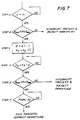
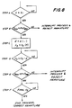
- Fig. 7 is a flowchart of a measurement feedback loop for displacing a fusing electrode in a predetermined manner as a function of time;
- Fig. 8 is a flowchart of a measurement feedback loop for displacing a fusing electrode in a predetermined manner as a function of electrode force.
- Fig. 9 is a flowchart of a force feedback loop for fusing armature wires with a predetermined force as a function of displacement;
- Fig. 10 is a flowchart of a force feedback loop for fusing armature wires with a predetermined force as a function of time.
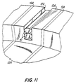
- Fig. 11 is a partial perspective view of a commutator slot and armature wires;
- Fig. 12 is a cross-sectional view of a commutator slot and armature wires prior to fusing;
- Fig. 13 is a cross-sectional view of a commutator slot and armature wires during the fusing operation;
- Fig. 14 is a perspective view of a stator of an electric motor;
- Fig. 15 is a top view, partly in section, of the stator of Fig. 14, equipped with a terminal board and terminal;
- Fig. 16 is a partial, cross-sectional view taken along line 16-16 of the stator of Fig. 15, with the stator positioned in the fusing machine prior to fusing; and
- Fig. 17 is the stator of Fig. 18 after fusing is completed.
-
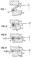
- Figs. 1 - 4 illustrate the process for fusing a
lead wire 10 of an armature to acommutator bar 12.Wire 10, covered byelectrical insulation 14, is passed under ahook 16 oncommutator bar 12. A highresistance tungsten electrode 18 contacts hook 16 at position A of Fig. 1. Electrode 18 applies pressure to hook 16, causing the hook to deform towardscommutator bar 12 to form the fused joint. During deformation, a portion of the hook envelops wire 10 (or several wires). - To achieve low current densities through the electrode, current is applied when the tip of
electrode 18 has maximum surface contact with the hook, as shown at position B of Fig. 2. Current flowing to commutator bar 12 (and into a low resistance mass electrode 106 (Fig. 5) passes alonghook 16 and throughwire 10, heating them. The heat vaporizes anyinsulaton 14 that is in contact withhook 16.Electrode 18 applies pressure to and deformshook 16, as current continues to flow through the hook. The electode deformshook 16 until the front end of the hook comes into contact with the commutator bar to be joined (position of Fig. 3). A portion of the current passes through the end ofhook 16 in its path through the commutator bar towards the mass electrode. Insulation vaporization continues in this phase.Wire 10 is not yet significantly deformed and has a diameter indicated by reference numeral 20. -
Electrode 18 deforms hook 16 (see Fig. 4) until a predetermined amount of thefront surface 22 of the hookcontacts commutator bar 12, and continues to apply current to the hook. The pressure and current are applied until the cohesion joint forms between thecontact surface 22 of the hook and the bar.Hook 16 andwire 10 deform further untilwire 10 has a predetermined diameter (designated by reference numeral 24). - The entire (designed)
hook surface 22 must be in cohesion contact with the commutator bar to produce a connection with sufficient mechanical resistance to prevent the contact from disconnecting when subjected to high centrifugal forces (high armature speeds). Also, thedeformed diameter 24 ofwire 10 must be within a predetermined range. This ensures that the mechanical resistance of the wire is acceptable, and that the wire contacts a sufficient hook surface area to give the connection the correct electric resistance.Insulation 14 must be entirely removed from the portion of the wire that contacts the hook surface, to give the connection the correct electrical resistance. - Referring to Fig. 5, the
armature 26 is firmly mounted and positioned on astationary work plane 28. A conventional angular positioning unit (not shown) typically aligns the commutator hook to be processed with theelectrode axis 30. A conventional rejectingunit 31 is provided for removing a defective armature fromwork plane 28. -
Electrode 18 is disposed inelectrode axis 30 and directly abovehook 16.Electrode 18 is releasably fixed to a supportingblock 32. Supportingblock 32 includesinternal passageways 34 for channeling water from a water supply. The water cools the electrode at predetermined rates and intervals. Supportingblock 32 is rigidly flanged to a firsthollow member 36 by screws 38. - A
cylindrical member 40 is seated on the bottom ofhollow member 36. A force transducer, such as aload cell 42, is seated incylindrical member 40. One end of apin 44 is fixed to hollowmember 36, and the other end engages arecess 46 incylindrical member 40.Pin 44 prevents cylindrical member 40 (and load cell 42) from rotating in respect tohollow member 36. -
Hollow member 36 connects to a secondhollow member 48 by a flange 50 and byscrews 52.Hollow member 36 is centered and slides on the bottom extension ofhollow member 48. A portion of the bottom ofhollow member 48 is maintained in contact with a protrudingmember 54 ofload cell 42. - The apparatus of this invention permits forces acting on hollow member 36 (caused by pressure against electrode 18) to compress
load cell 42.Hollow member 36 can translate relative tohollow member 48.Spacing 56 betweenhollow members roller 57 is fixed to hollowmember 36 and runs along supportingblock 58.Roller 57 maintains the proper electrode alignment on theelectrode axis 30. - Supporting
block 58 surroundshollow member 48, but is not in contact with it. Supportingblock 58 is rigidly fixed to aslide 64, which slides on stationary frame guides 66. - To vary the electrode rest position, (with respect to the armature supporting plane), supporting
block 58 includes abar end 68 which is axially fixed, but which is free to rotate inappendix 70 fo supportingblock 58. A threaded portion ofbar 68 engages a threadedblock 72, which is fixed to amain frame 74 of the apparatus by a screw 76.Slide 64 may be actuated by any suitable actuating means to adjust the electrode rest position to accomodate different commutator sizes. - A threaded
ball sleeve 78 is rigidly fixed tohollow member 48 by alid 80 and screws 82.Ball screw 84 engages threadedsleeve 78 and can be rotated to translatehollow member 48 alongelectrode axis 30.Hollow member 48 includes a bottom cavity 86 that receives the protruding portion ofball screw 84. The sides of cavity 86 do not contactball screw 84, thus allowing ball screw 84 to rotate relative tohollow member 48.Hollow member 48 will only translate. A stud member 88 projects fromhollow member 48, andcontacts supporting block 58 to prevent hollow member 48 (and hollow member 36) from rotating. Aconnection member 90 is flanged on its bottom end to supportingblock 58, and is held in place by screws 92. The other end ofmember 90 supports and is joined to drivegroup 94.Drive group 94 includes a low inertia dc motor, reduction gear, a tachometer, and an encoder.Ball screw shoulder 96 rests against bearing 98, which seats inconnection member 90. A threadedsleeve 100 connectsball screw 84 to the output drive shaft 102 of the dc motor, and ensures that ball screw 84 is axially positioned againstbearing 98. - A
mass electrode 106 is rigidly connected toarm 108, which is hinged to slide 64. The rest position ofmass electrode 106 may be adjusted to accomodate different commutator sizes by adjusting the position ofslide 64. An actuator and relative sensing devices movemass electrode 106, causing the electrode to contact the commutator bar to be fused. -
Electric supply cables 110 are connected to block 32 andarm 108. Electrical energy may be applied toelectrode 18 as a constant current, and may be integrated in time. Electrical energy may be applied at a predetermined electrode displacement or electrode force. - A rotation of motor output drive shaft 102 will cause ball screw 84 to rotate. Its engagement with
sleeve 100 will causehollow member 48,hollow member 36, andelectrode 18 to translate alongelectrode axis 30.Ball screw 84 converts the rotational motion of the motor into a translational motion ofelectrode 18 alongaxis 30. When electrode 18 encounters an opposing force exerted byhook 16,load cell 42 is compressed againsthollow member 48.Space 56 allowshollow member 36 to translate alonghollow member 48, and will allowload cell 42 to deform correspondingly. In a rest position, or whenelectrode 18 is moving but is not in contact withhook 16,hollow member 48 is supported by screw heads 112. - In an alternative embodiment,
load cell 42 is disposed beneath the commutator support block, onwork plane 28.Hollow members Load cell 42 deforms in response to the amount of force exerted onhook 16 whenelectrode 18 descends upon the hook. - Referring to fig. 6, several measurements may be obtained during the fusing process by connecting a motor 114, a
tachometer 116, an encoder 118 (which collectively formdrive group 94 of Fig. 5), and loadcell 42 to a suitable microprocessor-basedcontrol circuit 120. The measurable quantities include electrode displacement (hook deformation) and electrode pressure. The displacement is derived, usingencoder 118, from the number of turns of motor drive shaft 102.Load cell 42 measures the pressure or force resistance against the electrode. - The microprocessor and control circuitry store distinct displacement functions X(t) and X(p) and force functions P(x) and P(t), predetermined for each type of hook to be fused.
Microprocessor 120 changes the field conditions of motor 114 to control the motor torque. Signals received from load cell 42 (indicating electrode pressure) enable the microprocessor to modify the motor torque to satisfy force functions P(x) and P(t). Encoder signals providemicroprocessor 120 with displacement information, enabling the microprocessor to precisely lower (or raise)electrode 18 according to the displacement functions X(t) and X(p). The feedback loop control transmits the effects of changes made bymicroprocessor 120 on motor 114 back to the microprocessor, as feedback fromload cell 42 and encode 118. The feedback loop control constantly modifies the forces acting onelectrode 18 to ensure strict adherence to the proper displacement of force function. - The apparatus of this invention makes many other measurements and functions possible. For example, the electric supply to
electrode 18 is selectively variable for predetermined ranges and measured values of electrode displacement or electrode force. - Referring now to Figs. 7 and 8, the measurement feedback loop provides a means for precisely controlling the displacement of
electrode 18 throughout the entire fusing cycle. The measured feedback loop may have two variations:electrode 18 may be displaced as a function of time (fig. 7), or as a function of electrode force (fig. 8). - The process described in the flowchart of Fig. 7 is used for fusing operations involving small wires or for operations where the final wire deformation must be within very narrow tolerances. The measurement feedback control loop monitors the electrode displacement to prevent excessive deformation of
wire 10 by excessive electrode displacement. Excessive wire deformation increases the likelihood of wire breakage. The control loop also prevents too little displacement, which would result in a poorly fused wire and a bad electrical connection. - Motor output drive shaft 102 rotates
ball screw 84, causinghollow member 36 andelectrode 18 to translate alongelectrode axis 30 and to approachhook 16 at a predetermined speed. The displacement distance X is continuously monitored (step A) byencoder 118 andmicroprocessor 120. Whenelectrode 18 is displaced a predetermined distance X1 - corresponding to the point at which there is maximum surface contact betweenelectrode 18 and hook 16 - the electrode force measurement is verified (step B). If the force P acting upon the hook is not within a predetermined range, the process is interrupted andarmature 26 is rejected. Step B is a quality control step designed to reject an armature with a hook which does not support the desired pressure. For axemple, an armature with a hook formed of poor quality materials, or with a hook that is missing a wire, would not support the pressure and would be rejected. - If the force on
hook 16 is within the predetermined range, electrical current E is applied to the hook viaelectrode 18.Electrode 18 is displaced according to a displacement function X(t) for the type of hook being fused (step C). The displacement ofelectrode 18 is continually monitored (step D) until the electrode reaches a predetermined displacement value which is slightly less than the final displacement. Whenelectrode 18 reaches the proper displacement,load cell 42 again measures the electrode pressure (step E) to determine whether the hook will support a predetermined pressure. If the electrode pressure is not within the predetermined range,microprocessor 120 interrupts the cycle and rejectsarmature 26. If the electrode pressure is correct,encoder 118 andmicroprocessor 120 determine whether the displacement ofelectrode 18 has reached a final predetermined value (step F). The final displacement ofelectrode 18 corresponds to the point at which the electrode is sufficiently displaced to satisfactorily deformwire 10 underhook 16. Ifelectrode 18 has not been sufficiently displaced, the feedback loop waits until the electrode is sufficiently displaced. Excessive electrode displacement will causearmature 26 to be rejected. Whenelectrode 18 has been properly displaced according to step F, the cycle is interrupted, the armature is indexed for operation on the next hook, and the cycle begins again (step A). - Fig. 8 illustrates the second variation of the measurement feedback loop.
Electrode 18 is displaced as a function of the force applied to the electrode. Steps A, B, and D - F of the process typically are the same as the corresponding steps shown in Fig. 7 (i.e., whereelectrode 18 is displaced as a function of time). However, during step C,electrode 18 is displaced as a function of electrode force.Microprocessor 120 receives force data fromload cell 42, and acts on motor 114 to adjust electrode displacement according to the predetermined function X(p) for the hook being fused. Electrode displacement is continually monitored (step D) untilelectrode 18 reaches a predetermined displacement value which is slightly less than the final displacement, after which the process continues as previously described with respect to Fig. 7. - Referring now to Figs. 9 and 10, the force feedback loop provides a means for controlling the electrode pressure throughout the entire work cycle. The force feedback loop may have two variations: force may be applied to
electrode 18 as a funtion of electrode displacement (Fig. 9), or as a function of time (Fig. 10). - The process described in the flowchart of Fig. 9 controls the fusion process for wires with larger diameters. Greater tolerances are permitted for the final wire deformation under the hook when fusing large diameter wires than are permitted for thin wires. However, the final pressure values must be within a predetermined range to ensure a satisfactory cohesion joint. This is accomplished with an electrode force feedback control loop and
load cell 42. - Motor output drive shaft 102 rotates
ball screw 84, causinghollow member 36 andelectrode 18 to translate alongelectrode axis 30 and to approachhook 16 at a predetermined speed. The electrode force P is continuously monitored (step A) byload cell 42 andmicroprocessor 120. When electrode displacement X is determined byencoder 118 and microprocessor 120 (step B). If displacement X is not within a predetermined range, the process is interrupted andarmature 26 is rejected. Step B is a quality control step designed to ensure thatelectrode 18 is sufficiently displaced to properly contacthook 16 for applying electricity (i.e., there is maximum surface contact betweenelectrode 18 and hook 16). Maximum surface contact between the electrode and the hook results in low current densities throughelectrode 18, preventing excessive electrode wear. - If the electrode displacement is within the predetermined range, electrical current E is applied to hook 16 via
electrode 18. Pressure is applied toelectrode 18 as a function of displacement according to a force function P(x) for the hook being fused (step C). A different force function typically is stored inmicroprocessor circuitry 120 for each type of hook that electrode 18 will deform. The force applied toelectrode 18 is continually monitored byload cell 42 and adjusted by the action ofmicroprocessor 120 to maintain the desired pressure as a function of displacement. The force is monitored (step D) until it reaches a final predetermined value P2. When the proper force has been applied,encoder 118 andmicroprocessor 120 again determine the electrode displacement (step E) to determine whether the force function applied to the hook produced the correct electrode displacement (and hook deformation). If the electrode displacement is correct, the fusing cycle is interrupted, the armature is indexed for operation on the next hook, and the cycle begins again (step A). If the electrode displacement is not within the predetermined range, the process continues to an additional step (step F). If the electrode displacement exceeds the maximum displacement, the cycle begins again at step C. If the electrode displacement is less than the maximum allowable displacement,microprocessor 120 interrupts the cycle and rejectsarmature 26. - Fig. 10 illustrates the second variation of the force feedback loop. Force is applied to
electrode 18 as a function of time. Steps A, B, and D - F of the process typically are the same as the corresponding steps shown in Fig. 9 (i.e. where force is applied toelectrode 18 as a function of displacement). However, during step C, force is applied toelectrode 18 as a function of time.Microprocessor 120 receives force data fromload cell 42, and acts on motor 114 to adjust the electrode force according to the predetermined function P(t) for the hook being fused. Electrode force is continually monitored (step D) until the force reaches a predetermined force value P2, after which the process continues as previously described with respect to Fig. 9. - Although the invention has been described with respect to fusing
hook members 16 andarmature wires 10 to commutator bars 12, the invention is equally applicable to fusing armature wires into commutator slots. The same feedback loop displacement control or feedback loop force control governs the fusing operation. - Referring to Figs. 11 - 13,
wires 10 are inserted, generally one on top of the other, inslot 122 with appropriate lead terminating equipment.Insulators 124 separate one commutator segment from another. The slots are cut in a commutator "ridge" 126. The commutator running surface is designated byreference numeral 128. -
Electrode 18contacts commutator ridge 126, applying pressure to deform the commutator slot aroundwires 10. It is most important to have a precise electrode displacement when current is applied. The optimal displacement X1 (Fig. 12) coincides with maximum surface contact beweenelectrode 18 andcommutator ridge 126. Current flowing throughelectrode 18 generates heat, which initially heats themetal surrounding slot 122, and causes thewire insulation 14 contacting the sides of slot 122 (the slot is usually designed to tightly hold the wires) to vaporize.Electrode 18 exerts force towards the slot bottom, causing plastic deformation ofwires 10 andslot 122. - The plastic deformation increases the amount of heated
metal contacting wires 10. This further vaporizesinsulation 14. Fig. 13 shows a final condition of the slot-fusing process, with the metal ofslot 122 tightly surrounding thedeformed wires 10. The final slot deformation X2 (Fig. 13) must be within predetermined tolerances to ensure a proper connection and to ensure that all wires are properly positioned. - As described for deforming a hook,
electrode 18 applies force tocommutator ridge 126 as a function of displacement, according to a predetermined force function.Load cell 42 andmicroprocessor 120 form a closed loop system to continually monitor and adjust the force applied, according to the force function. Applying force according to the predetermined function ensures that large wires will be tightly surrounded by metal from the walls ofslot 122 and ensures that the connection will have the correct mechanical and electrical properties.Microprocessor circuitry 120 stores a distinct force function for each slot connection variation (i.e. geometry of the slot, wire size, wire and commutator material, and type of wire insulation). - Referring now to Figs. 14 - 17, the methods and apparatus of the present invention may be used to fuse a
stator lead wire 130 to a hook member to thestator 132 of an electric motor. Stator hooks are fused in substantially the same manner as commutator hooks. Stator hooks may be fused using the same force and displacement feedback loops that are used to fuse commutator hooks 16. - Fig. 14 shows
stator 132, withlongitudinal axis 134, wrapped withcoils poles Openings 144 are provided adjacent thelamination stack 146 for receiving and mounting aterminal board 148 against an end face ofstack 146. Each of projectingmembers 150 frictionally engages a terminal 152 for receivingstator lead wire 130 and for providing external lead connections to the stator. - During winding,
lead wire 130 typically is anchored to auxiliary grippers (not shown). During a termination operation, shown in Fig. 15,lead wire 130 is placed between ahook 154 and the main body ofterminal 152.Hook 154 typically is then deformed slightly to holdlead wire 130 in the proper position whilestator 132 is transferred to the fusing machine.Hook 154 is formed by cutting a central portion of the body ofterminal 152 and bending the central portion upwards. - Fig. 16 shows stator 132 positioned in a fusing machine between fusing
electrode 18 andmass electrode 106.Electrodes horizontal axis 156. The stator is positioned to alignhook 154 inaxis 156, betweenelectrodes axis 156 to contacthook 154 and to fuse the hook andlead wire 130. - Each of
electrodes axis 156 by independently-controlled drive mechanisms, which typically are equipped with a force transducer and a displacement sensor. One skilled in the art will realize that the apparatus and methods described herein for fusing armature hooks are equally applicable to fusing stator hooks. For example,stator hook 154 can be fused according to a predetermined force or displacement function, using a feedback force or displacement control loop (e.g., as shown in Figs. 7 - 10). Also, electric current may be selectively applied toelectrode 18 for predetermined values of electrode displacement or force. fig. 17 shows the final, fused connection ofhook 154 andlead wire 130. - If there are a large number of terminals and lead wires on the stator, it may be necessary to simultaneously fuse more than one hook at a time. This simultaneous fusing operation can be performed with a plurality of individual fusing electrodes that are connected to a common drive mechanism, with common displacement and force sensors. The individual electrodes fuse several hooks at the same time.
- It will be understood that the foregoing is merely illustrative of the principles of the invention, and that various modifications can be made by those skilled in the art without departing from the scope and spirit of the invention as defined by the claims.
Claims (13)
- Fusing apparatus for connecting a lead wire (10) to an electrically conductive section (16) of an armature or a stator (132) comprising an electrode (18) to contact said section (16) and to apply electric current to heat said section (16) and the lead wire (10) in thermal contact with said electrode (18), means (94) for moving said electrode (18) to deform said section (16) around said lead wire (10) by applying force (P) onto said section, means (42,118) for monitoring relative displacement occurring between said electrode (18) and said section (16), and characterised by means (120) responsive to said means for monitoring for controlling said means for moving (94) in order to cause the relative displacement of said electrode and said section to conform to a predetermined displacement function (X(P), X(t)).
- The apparatus defined in claim 1, wherein said predetermined displacement function is a function (X(t)) which relates displacement to elapsed time.
- The apparatus defined in claim 1 further comprising means for monitoring the force being applied by said electrode to said section (16).
- The apparatus defined in claim 3, wherein said predetermined displacement function is a function (X(P)) which relates displacement to force.
- The apparatus defined in claim 1 further comprising:means responsive to said means for monitoring (42,118) for causing said electric current to flow through said electrode (18) and said section (16) when a predetermined relative displacement between said electrode and said section has occurred.
- The apparatus defined in claims 1 or 3 further comprising:means responsive to said means for controlling (120) for interrupting said fusing apparatus and for rejecting said armature or said stator (132) if said displacement between said electrode (18) and said section (16) or said force being by applied by said electrode to said section deviates from a predetermined relationship by more than a predetermined amount.
- Fusing method for connecting a lead wire (10) to an electrically conductive section (16) of an armature or a stator (132), wherein said method comprises contacting by means of an electrode (18) said section (16) to apply electric current to heat said section (16) and the lead wire (10) in thermal contact with said electrode (18), moving said electrode (18) to deform said section (16) around said lead wire (10) by applying force (P) onto said section, monitoring relative displacement between said electrode (18) and said section (16), and characterised by controlling movement of said electrode (18) responsive to said monitoring step to cause the relative displacement between said electrode and said section to conform to a predetermined displacement function (X(P), X(t)).
- The method defined in claim 7, wherein said predetermined displacement function is a function (X(t)) which relates displacement to elapsed time.
- The method defined in claim 7, comprising monitoring the force being applied by said electrode to said section (16)
- The method defined in claim 9, wherein said predetermined displacement function is a function (X(P)) which relates displacement to force.
- The method defined in claim 7 comprising:causing said electric current to flow through said electrode (18) and said section (16) when a predetermined relative displacement between said electrode and said section has occurred.
- The method defined in claims 7 or 9 comprising:interrupting and rejecting said armature or said stator (132) if said displacement between said electrode (18) and said section (16) or said force being by applied by said electrode to said section deviates from a predetermined relationship by more than a predetermined amount.
- The method defined in claim 7 comprising:supplying selectively variable electric power to the electrode (18) for predetermined ranges of the relative displacement (X).
Applications Claiming Priority (5)
| Application Number | Priority Date | Filing Date | Title |
|---|---|---|---|
| US41227989A | 1989-09-25 | 1989-09-25 | |
| US412279 | 1989-09-25 | ||
| US436633 | 1989-11-15 | ||
| US07/436,633 US5063279A (en) | 1989-09-25 | 1989-11-15 | Methods and apparatus for fusing armature and stator wires |
| EP90116084A EP0419849B1 (en) | 1989-09-25 | 1990-08-22 | Methods and apparatus for fusing armature and stator wires |
Related Parent Applications (2)
| Application Number | Title | Priority Date | Filing Date |
|---|---|---|---|
| EP90116084A Division EP0419849B1 (en) | 1989-09-25 | 1990-08-22 | Methods and apparatus for fusing armature and stator wires |
| EP90116084.6 Division | 1990-08-22 |
Publications (3)
| Publication Number | Publication Date |
|---|---|
| EP0584841A2 EP0584841A2 (en) | 1994-03-02 |
| EP0584841A3 EP0584841A3 (en) | 1994-05-18 |
| EP0584841B1 true EP0584841B1 (en) | 1999-06-23 |
Family
ID=27021706
Family Applications (2)
| Application Number | Title | Priority Date | Filing Date |
|---|---|---|---|
| EP90116084A Expired - Lifetime EP0419849B1 (en) | 1989-09-25 | 1990-08-22 | Methods and apparatus for fusing armature and stator wires |
| EP93117137A Expired - Lifetime EP0584841B1 (en) | 1989-09-25 | 1990-08-22 | Methods and apparatus for fusing armature or stator wires |
Family Applications Before (1)
| Application Number | Title | Priority Date | Filing Date |
|---|---|---|---|
| EP90116084A Expired - Lifetime EP0419849B1 (en) | 1989-09-25 | 1990-08-22 | Methods and apparatus for fusing armature and stator wires |
Country Status (6)
| Country | Link |
|---|---|
| US (1) | US5063279A (en) |
| EP (2) | EP0419849B1 (en) |
| JP (1) | JPH03118747A (en) |
| AT (2) | ATE181523T1 (en) |
| DE (3) | DE69033184T2 (en) |
| ES (1) | ES2056322T3 (en) |
Cited By (2)
| Publication number | Priority date | Publication date | Assignee | Title |
|---|---|---|---|---|
| US9172289B2 (en) | 2012-11-27 | 2015-10-27 | Regal Beloit America, Inc. | Wire guide for use in an electric machine |
| US9698645B2 (en) | 2013-03-14 | 2017-07-04 | Regal Beloit America, Inc. | Electric machine and associated method |
Families Citing this family (29)
| Publication number | Priority date | Publication date | Assignee | Title |
|---|---|---|---|---|
| US5241486A (en) * | 1989-11-30 | 1993-08-31 | Axis U.S.A., Inc. | Methods and apparatus for marking and identifying hooks of electric motors |
| US5552572A (en) * | 1989-11-30 | 1996-09-03 | Axis Usa, Inc. | Methods and apparatus for identifying hooks of electric motors |
| US5122975A (en) * | 1989-11-30 | 1992-06-16 | Axis Usa, Inc. | Methods and apparatus for marking and identifying hooks of electric motors |
| US5386092A (en) * | 1991-11-04 | 1995-01-31 | Unitek Equipment Inc. | Fast response weld head |
| US5300753A (en) * | 1992-06-25 | 1994-04-05 | Axis Usa, Incorporated | Methods and apparatus for fusing electrical conductors |
| US5331130A (en) * | 1992-09-22 | 1994-07-19 | Odawara Automation, Inc. | Method and apparatus for fusing terminal or commutator wire connections on an armature or stator |
| US5360958A (en) * | 1993-05-17 | 1994-11-01 | Delco Electronics Corporation | Welding apparatus having coaxial welding electrodes |
| US5418347A (en) * | 1993-05-19 | 1995-05-23 | Odawara Automation Inc. | Method and apparatus for fusing terminal or commutator wire connections using a trigger current |
| US5504298A (en) * | 1993-06-04 | 1996-04-02 | Axis Usa, Inc. | Methods and apparatus for detecting electrode separation |
| US5484976A (en) * | 1993-10-01 | 1996-01-16 | Axis Usa, Inc. | Fusing methods and apparatus for use in making dynamo-electric machines |
| US5486672A (en) * | 1993-12-13 | 1996-01-23 | Axis Usa, Inc. | Methods and apparatus for commutator fusing |
| US5525774A (en) * | 1994-08-16 | 1996-06-11 | Globe Products Inc. | Method and apparatus for fusing lead wires of coils to terminals |
| FR2728820A1 (en) * | 1994-12-30 | 1996-07-05 | Renault | RESISTANCE WELDING DEVICE WITH EFFORT CONTROL |
| US5660742A (en) * | 1995-03-31 | 1997-08-26 | Joyal Products, Inc. | Insulated wire termination, method, and machine |
| EP0747697A1 (en) | 1995-06-07 | 1996-12-11 | AXIS SpA | Method and apparatus for acoustic testing of armatures |
| US5831235A (en) * | 1996-06-24 | 1998-11-03 | Cecil; Dimitrios G. | Apparatus and method of welding a tube and bracket assembly |
| US5828028A (en) * | 1996-06-24 | 1998-10-27 | Cecil; Dimitrios G. | Hot forging method and apparatus |
| DE69813993D1 (en) | 1997-10-29 | 2003-06-05 | Axis Spa | Device and method for manufacturing fittings |
| JP2000126869A (en) * | 1998-08-20 | 2000-05-09 | Seiwa Seisakusho:Kk | Resistance welding equipment |
| US6474435B1 (en) | 2000-09-07 | 2002-11-05 | Trw Vehicle Safety Systems Inc. | Means for electrical connection of components in a vehicle occupant protection system |
| US6911615B2 (en) * | 2000-11-02 | 2005-06-28 | Leander Reischmann | Welding head |
| US6545243B1 (en) * | 2001-09-14 | 2003-04-08 | Delco Remy America, Inc. | Dynamic weld power termination for hot-staking armature commutators |
| US6903298B2 (en) * | 2003-08-25 | 2005-06-07 | General Motors Corporation | Resistance welding control method |
| IT1394587B1 (en) | 2009-04-29 | 2012-07-05 | Atop Spa | EQUIPMENT AND METHOD FOR WINDING AND FINISHING NUCLEI FOR DYNAMIC ELECTRIC MACHINES |
| US20150214820A1 (en) * | 2014-01-24 | 2015-07-30 | Remy Technologies, Llc | Hairpin joint |
| US10330730B2 (en) | 2014-07-22 | 2019-06-25 | Atop S.P.A. | Method and apparatus for determining the Electric resistance of a coil connection of armature coils |
| DE102015000439A1 (en) * | 2015-01-14 | 2016-07-14 | Audi Ag | Method for winding a winding carrier |
| CN106911232B (en) * | 2017-04-01 | 2024-04-16 | 宁波韵升电驱动技术有限公司 | Pressing device and pressing method for armature commutator |
| CN110860775B (en) * | 2019-12-10 | 2021-09-03 | 璋祐科技(深圳)有限公司 | Full-automatic unilateral spot welding machine |
Family Cites Families (18)
| Publication number | Priority date | Publication date | Assignee | Title |
|---|---|---|---|---|
| US3045103A (en) * | 1960-10-10 | 1962-07-17 | Warner Samuel | Commutator fusing machine |
| US3449541A (en) * | 1966-01-20 | 1969-06-10 | Martin Marietta Corp | Apparatus for producing resistance welds |
| US3514569A (en) * | 1967-12-28 | 1970-05-26 | Raytheon Co | Resistance welder |
| US3727822A (en) * | 1970-10-05 | 1973-04-17 | Gen Electric | Electromagnetic force system for integrated circuit fabrication |
| US3781981A (en) * | 1972-02-28 | 1974-01-01 | Nippon Denko | Method for making armature-commutator assembly having armature winding of very small diameter |
| DE2538295A1 (en) * | 1975-08-28 | 1977-03-10 | Bosch Gmbh Robert | PROCESS FOR PRODUCING AN ELECTRICALLY CONDUCTIVE AND MECHANICALLY FIXED CONNECTION OF ALUMINUM CONDUCERS TO COPPER COMMUTATORS |
| US4079225A (en) * | 1976-08-04 | 1978-03-14 | Warner Allan S | Fiber optic/photon detector for brazing machine |
| US4249068A (en) * | 1978-09-28 | 1981-02-03 | Joyal Products, Inc. | Method and apparatus for controlling heat energy of a bonding transformer |
| US4224496A (en) * | 1978-10-12 | 1980-09-23 | Joyal Products, Inc. | Method and apparatus for controlling a brazing machine |
| DE3018384A1 (en) * | 1980-05-14 | 1981-11-19 | Rossell Electronique S.A., Lausanne | METHOD FOR ATTACHING AT LEAST ONE ELECTRODE, FEEDING DEVICE AND RECEIVER FOR CARRYING OUT THIS METHOD, AND USE OF THE METHOD, THE FEEDING DEVICE AND / OR THE RECEIVER |
| US4510370A (en) * | 1980-11-03 | 1985-04-09 | Joyal Products, Inc. | Fusing machine |
| US4371772A (en) * | 1980-11-03 | 1983-02-01 | Joyal Products, Inc. | Plural shaft electrode support for fusing machine |
| US4504724A (en) * | 1980-11-03 | 1985-03-12 | Joyal Products, Inc. | Fusing machine |
| US4451722A (en) * | 1980-11-03 | 1984-05-29 | Joyal Products, Inc. | Fusing machine |
| JPS5822861U (en) * | 1981-07-31 | 1983-02-12 | マブチモ−タ−株式会社 | Commutator device for small motors |
| US4419558A (en) * | 1981-11-23 | 1983-12-06 | Wagen Of America, Inc. | Apparatus and method for monitoring and controlling resistance spot welding |
| US4562330A (en) * | 1983-09-09 | 1985-12-31 | Digimetrics, Inc. | Spot weld quality monitoring system |
| DE3711771A1 (en) * | 1987-04-08 | 1988-10-27 | Sts Systemtechnik Und Software | Method and arrangement for process control in spot welding |
-
1989
- 1989-11-15 US US07/436,633 patent/US5063279A/en not_active Expired - Lifetime
-
1990
- 1990-08-22 EP EP90116084A patent/EP0419849B1/en not_active Expired - Lifetime
- 1990-08-22 DE DE69033184T patent/DE69033184T2/en not_active Expired - Lifetime
- 1990-08-22 AT AT93117137T patent/ATE181523T1/en not_active IP Right Cessation
- 1990-08-22 ES ES90116084T patent/ES2056322T3/en not_active Expired - Lifetime
- 1990-08-22 DE DE69008980T patent/DE69008980T2/en not_active Expired - Lifetime
- 1990-08-22 AT AT90116084T patent/ATE105755T1/en not_active IP Right Cessation
- 1990-08-22 EP EP93117137A patent/EP0584841B1/en not_active Expired - Lifetime
- 1990-08-22 DE DE199090116084T patent/DE419849T1/en active Pending
- 1990-09-25 JP JP2256776A patent/JPH03118747A/en active Pending
Cited By (2)
| Publication number | Priority date | Publication date | Assignee | Title |
|---|---|---|---|---|
| US9172289B2 (en) | 2012-11-27 | 2015-10-27 | Regal Beloit America, Inc. | Wire guide for use in an electric machine |
| US9698645B2 (en) | 2013-03-14 | 2017-07-04 | Regal Beloit America, Inc. | Electric machine and associated method |
Also Published As
| Publication number | Publication date |
|---|---|
| EP0419849A1 (en) | 1991-04-03 |
| DE69008980T2 (en) | 1994-09-08 |
| DE69008980D1 (en) | 1994-06-23 |
| DE69033184T2 (en) | 2000-03-09 |
| EP0584841A2 (en) | 1994-03-02 |
| DE69033184D1 (en) | 1999-07-29 |
| EP0419849B1 (en) | 1994-05-18 |
| ATE181523T1 (en) | 1999-07-15 |
| ATE105755T1 (en) | 1994-06-15 |
| DE419849T1 (en) | 1993-11-04 |
| ES2056322T3 (en) | 1994-10-01 |
| US5063279A (en) | 1991-11-05 |
| EP0584841A3 (en) | 1994-05-18 |
| JPH03118747A (en) | 1991-05-21 |
Similar Documents
| Publication | Publication Date | Title |
|---|---|---|
| EP0584841B1 (en) | Methods and apparatus for fusing armature or stator wires | |
| US20050210670A1 (en) | Wire loader | |
| JP2764221B2 (en) | Automatic wire crimping connection device and method | |
| JPH0821603B2 (en) | Fine wire-bonded head driven by voice coil | |
| EP0429766B1 (en) | Methods and apparatus for marking and identifying hooks of electric motors | |
| USRE30001E (en) | Methods and apparatus for making electrical interconnections | |
| EP0575857A1 (en) | Methods and apparatus for fusing electrical conductors | |
| US5111015A (en) | Apparatus and method for fusing wire | |
| US4148137A (en) | Apparatus for use in making electrical interconnections | |
| US5317125A (en) | Fusing apparatus with temperature control | |
| US5241486A (en) | Methods and apparatus for marking and identifying hooks of electric motors | |
| US20040055354A1 (en) | Method and device for quality assurance of crimp joints | |
| US4035910A (en) | Methods and apparatus for use in making electrical interconnections | |
| US5418347A (en) | Method and apparatus for fusing terminal or commutator wire connections using a trigger current | |
| US4249154A (en) | Temperature responsive electrical switching device and method of calibrating | |
| JPH03118934A (en) | Crimping press for crimping conduction terminal to conductor and method for measuring quality of crimped terminal end thereof | |
| US5486672A (en) | Methods and apparatus for commutator fusing | |
| WO2022098697A1 (en) | Methods of operating a wire bonding machine, including methods of monitoring an accuracy of bonding force on a wire bonding machine, and related methods | |
| JPH0957581A (en) | Life detector for tool gripper | |
| JP2000114086A (en) | Coil winding device | |
| EP0629028A2 (en) | Methods and apparatus for marking and identifying hooks of electric motor collectors | |
| CN115156973B (en) | Feeding device of CNC (computerized numerical control) processing machine tool | |
| JP4270558B2 (en) | Electric heat caulking joining device | |
| JP3090395B2 (en) | Electric soldering iron device | |
| JP4639765B2 (en) | Varnish impregnation apparatus and varnish impregnation method |
Legal Events
| Date | Code | Title | Description |
|---|---|---|---|
| PUAI | Public reference made under article 153(3) epc to a published international application that has entered the european phase |
Free format text: ORIGINAL CODE: 0009012 |
|
| AC | Divisional application: reference to earlier application |
Ref document number: 419849 Country of ref document: EP |
|
| AK | Designated contracting states |
Kind code of ref document: A2 Designated state(s): AT BE CH DE ES FR GB IT LI NL SE |
|
| PUAL | Search report despatched |
Free format text: ORIGINAL CODE: 0009013 |
|
| AK | Designated contracting states |
Kind code of ref document: A3 Designated state(s): AT BE CH DE ES FR GB IT LI NL SE |
|
| 17P | Request for examination filed |
Effective date: 19941108 |
|
| 17Q | First examination report despatched |
Effective date: 19970522 |
|
| GRAG | Despatch of communication of intention to grant |
Free format text: ORIGINAL CODE: EPIDOS AGRA |
|
| GRAG | Despatch of communication of intention to grant |
Free format text: ORIGINAL CODE: EPIDOS AGRA |
|
| GRAG | Despatch of communication of intention to grant |
Free format text: ORIGINAL CODE: EPIDOS AGRA |
|
| GRAH | Despatch of communication of intention to grant a patent |
Free format text: ORIGINAL CODE: EPIDOS IGRA |
|
| RAP1 | Party data changed (applicant data changed or rights of an application transferred) |
Owner name: AXIS S.P.A. |
|
| GRAH | Despatch of communication of intention to grant a patent |
Free format text: ORIGINAL CODE: EPIDOS IGRA |
|
| GRAH | Despatch of communication of intention to grant a patent |
Free format text: ORIGINAL CODE: EPIDOS IGRA |
|
| GRAA | (expected) grant |
Free format text: ORIGINAL CODE: 0009210 |
|
| AC | Divisional application: reference to earlier application |
Ref document number: 419849 Country of ref document: EP |
|
| AK | Designated contracting states |
Kind code of ref document: B1 Designated state(s): AT BE CH DE ES FR GB IT LI NL SE |
|
| PG25 | Lapsed in a contracting state [announced via postgrant information from national office to epo] |
Ref country code: SE Free format text: THE PATENT HAS BEEN ANNULLED BY A DECISION OF A NATIONAL AUTHORITY Effective date: 19990623 Ref country code: NL Free format text: LAPSE BECAUSE OF FAILURE TO SUBMIT A TRANSLATION OF THE DESCRIPTION OR TO PAY THE FEE WITHIN THE PRESCRIBED TIME-LIMIT Effective date: 19990623 Ref country code: ES Free format text: THE PATENT HAS BEEN ANNULLED BY A DECISION OF A NATIONAL AUTHORITY Effective date: 19990623 Ref country code: BE Free format text: LAPSE BECAUSE OF FAILURE TO SUBMIT A TRANSLATION OF THE DESCRIPTION OR TO PAY THE FEE WITHIN THE PRESCRIBED TIME-LIMIT Effective date: 19990623 Ref country code: AT Free format text: LAPSE BECAUSE OF FAILURE TO SUBMIT A TRANSLATION OF THE DESCRIPTION OR TO PAY THE FEE WITHIN THE PRESCRIBED TIME-LIMIT Effective date: 19990623 |
|
| REF | Corresponds to: |
Ref document number: 181523 Country of ref document: AT Date of ref document: 19990715 Kind code of ref document: T |
|
| REG | Reference to a national code |
Ref country code: CH Ref legal event code: EP |
|
| REF | Corresponds to: |
Ref document number: 69033184 Country of ref document: DE Date of ref document: 19990729 |
|
| ET | Fr: translation filed | ||
| ITF | It: translation for a ep patent filed |
Owner name: BARZANO'E ZANARDO S.P.A. |
|
| REG | Reference to a national code |
Ref country code: CH Ref legal event code: NV Representative=s name: ISLER & PEDRAZZINI AG |
|
| NLV1 | Nl: lapsed or annulled due to failure to fulfill the requirements of art. 29p and 29m of the patents act | ||
| PLBQ | Unpublished change to opponent data |
Free format text: ORIGINAL CODE: EPIDOS OPPO |
|
| PLBI | Opposition filed |
Free format text: ORIGINAL CODE: 0009260 |
|
| PLBF | Reply of patent proprietor to notice(s) of opposition |
Free format text: ORIGINAL CODE: EPIDOS OBSO |
|
| 26 | Opposition filed |
Opponent name: ATOP S.P.A. Effective date: 20000323 |
|
| PLBF | Reply of patent proprietor to notice(s) of opposition |
Free format text: ORIGINAL CODE: EPIDOS OBSO |
|
| PLBF | Reply of patent proprietor to notice(s) of opposition |
Free format text: ORIGINAL CODE: EPIDOS OBSO |
|
| REG | Reference to a national code |
Ref country code: GB Ref legal event code: IF02 |
|
| PLBO | Opposition rejected |
Free format text: ORIGINAL CODE: EPIDOS REJO |
|
| APAC | Appeal dossier modified |
Free format text: ORIGINAL CODE: EPIDOS NOAPO |
|
| APAC | Appeal dossier modified |
Free format text: ORIGINAL CODE: EPIDOS NOAPO |
|
| APAC | Appeal dossier modified |
Free format text: ORIGINAL CODE: EPIDOS NOAPO |
|
| APAA | Appeal reference recorded |
Free format text: ORIGINAL CODE: EPIDOS REFN |
|
| PGFP | Annual fee paid to national office [announced via postgrant information from national office to epo] |
Ref country code: GB Payment date: 20050805 Year of fee payment: 16 |
|
| APAH | Appeal reference modified |
Free format text: ORIGINAL CODE: EPIDOSCREFNO |
|
| APBU | Appeal procedure closed |
Free format text: ORIGINAL CODE: EPIDOSNNOA9O |
|
| PLBN | Opposition rejected |
Free format text: ORIGINAL CODE: 0009273 |
|
| STAA | Information on the status of an ep patent application or granted ep patent |
Free format text: STATUS: OPPOSITION REJECTED |
|
| 27O | Opposition rejected |
Effective date: 20060228 |
|
| GBPC | Gb: european patent ceased through non-payment of renewal fee |
Effective date: 20060822 |
|
| REG | Reference to a national code |
Ref country code: CH Ref legal event code: PCAR Free format text: ISLER & PEDRAZZINI AG;POSTFACH 1772;8027 ZUERICH (CH) |
|
| PG25 | Lapsed in a contracting state [announced via postgrant information from national office to epo] |
Ref country code: GB Free format text: LAPSE BECAUSE OF NON-PAYMENT OF DUE FEES Effective date: 20060822 |
|
| PGFP | Annual fee paid to national office [announced via postgrant information from national office to epo] |
Ref country code: FR Payment date: 20090819 Year of fee payment: 20 |
|
| PGFP | Annual fee paid to national office [announced via postgrant information from national office to epo] |
Ref country code: CH Payment date: 20090824 Year of fee payment: 20 |
|
| PGFP | Annual fee paid to national office [announced via postgrant information from national office to epo] |
Ref country code: DE Payment date: 20091026 Year of fee payment: 20 |
|
| REG | Reference to a national code |
Ref country code: CH Ref legal event code: PL |
|
| PG25 | Lapsed in a contracting state [announced via postgrant information from national office to epo] |
Ref country code: IT Free format text: LAPSE BECAUSE OF NON-PAYMENT OF DUE FEES Effective date: 20090822 |
|
| PGFP | Annual fee paid to national office [announced via postgrant information from national office to epo] |
Ref country code: IT Payment date: 20090803 Year of fee payment: 20 |
|
| PGRI | Patent reinstated in contracting state [announced from national office to epo] |
Ref country code: IT Effective date: 20110616 |
|
| PG25 | Lapsed in a contracting state [announced via postgrant information from national office to epo] |
Ref country code: DE Free format text: LAPSE BECAUSE OF EXPIRATION OF PROTECTION Effective date: 20100822 |