EP0584637A2 - Method and apparatus for recognizing meandering in printed matter test system and method and apparatus for correcting image pickup position in this system - Google Patents
Method and apparatus for recognizing meandering in printed matter test system and method and apparatus for correcting image pickup position in this system Download PDFInfo
- Publication number
- EP0584637A2 EP0584637A2 EP93112795A EP93112795A EP0584637A2 EP 0584637 A2 EP0584637 A2 EP 0584637A2 EP 93112795 A EP93112795 A EP 93112795A EP 93112795 A EP93112795 A EP 93112795A EP 0584637 A2 EP0584637 A2 EP 0584637A2
- Authority
- EP
- European Patent Office
- Prior art keywords
- meandering
- image data
- output
- printed matter
- test
- Prior art date
- Legal status (The legal status is an assumption and is not a legal conclusion. Google has not performed a legal analysis and makes no representation as to the accuracy of the status listed.)
- Withdrawn
Links
Images


Classifications
-
- H—ELECTRICITY
- H04—ELECTRIC COMMUNICATION TECHNIQUE
- H04N—PICTORIAL COMMUNICATION, e.g. TELEVISION
- H04N1/00—Scanning, transmission or reproduction of documents or the like, e.g. facsimile transmission; Details thereof
- H04N1/04—Scanning arrangements, i.e. arrangements for the displacement of active reading or reproducing elements relative to the original or reproducing medium, or vice versa
- H04N1/047—Detection, control or error compensation of scanning velocity or position
-
- H—ELECTRICITY
- H04—ELECTRIC COMMUNICATION TECHNIQUE
- H04N—PICTORIAL COMMUNICATION, e.g. TELEVISION
- H04N1/00—Scanning, transmission or reproduction of documents or the like, e.g. facsimile transmission; Details thereof
- H04N1/04—Scanning arrangements, i.e. arrangements for the displacement of active reading or reproducing elements relative to the original or reproducing medium, or vice versa
- H04N1/12—Scanning arrangements, i.e. arrangements for the displacement of active reading or reproducing elements relative to the original or reproducing medium, or vice versa using the sheet-feed movement or the medium-advance or the drum-rotation movement as the slow scanning component, e.g. arrangements for the main-scanning
-
- H—ELECTRICITY
- H04—ELECTRIC COMMUNICATION TECHNIQUE
- H04N—PICTORIAL COMMUNICATION, e.g. TELEVISION
- H04N1/00—Scanning, transmission or reproduction of documents or the like, e.g. facsimile transmission; Details thereof
- H04N1/04—Scanning arrangements, i.e. arrangements for the displacement of active reading or reproducing elements relative to the original or reproducing medium, or vice versa
- H04N1/19—Scanning arrangements, i.e. arrangements for the displacement of active reading or reproducing elements relative to the original or reproducing medium, or vice versa using multi-element arrays
- H04N1/191—Scanning arrangements, i.e. arrangements for the displacement of active reading or reproducing elements relative to the original or reproducing medium, or vice versa using multi-element arrays the array comprising a one-dimensional array, or a combination of one-dimensional arrays, or a substantially one-dimensional array, e.g. an array of staggered elements
- H04N1/192—Simultaneously or substantially simultaneously scanning picture elements on one main scanning line
- H04N1/193—Simultaneously or substantially simultaneously scanning picture elements on one main scanning line using electrically scanned linear arrays, e.g. linear CCD arrays
-
- H—ELECTRICITY
- H04—ELECTRIC COMMUNICATION TECHNIQUE
- H04N—PICTORIAL COMMUNICATION, e.g. TELEVISION
- H04N2201/00—Indexing scheme relating to scanning, transmission or reproduction of documents or the like, and to details thereof
- H04N2201/024—Indexing scheme relating to scanning, transmission or reproduction of documents or the like, and to details thereof deleted
- H04N2201/02406—Arrangements for positioning elements within a head
- H04N2201/02416—Rotational positioning, i.e. with respect to an axis
-
- H—ELECTRICITY
- H04—ELECTRIC COMMUNICATION TECHNIQUE
- H04N—PICTORIAL COMMUNICATION, e.g. TELEVISION
- H04N2201/00—Indexing scheme relating to scanning, transmission or reproduction of documents or the like, and to details thereof
- H04N2201/024—Indexing scheme relating to scanning, transmission or reproduction of documents or the like, and to details thereof deleted
- H04N2201/02406—Arrangements for positioning elements within a head
- H04N2201/02439—Positioning method
-
- H—ELECTRICITY
- H04—ELECTRIC COMMUNICATION TECHNIQUE
- H04N—PICTORIAL COMMUNICATION, e.g. TELEVISION
- H04N2201/00—Indexing scheme relating to scanning, transmission or reproduction of documents or the like, and to details thereof
- H04N2201/024—Indexing scheme relating to scanning, transmission or reproduction of documents or the like, and to details thereof deleted
- H04N2201/028—Indexing scheme relating to scanning, transmission or reproduction of documents or the like, and to details thereof deleted for picture information pick-up
- H04N2201/03—Indexing scheme relating to scanning, transmission or reproduction of documents or the like, and to details thereof deleted for picture information pick-up deleted
- H04N2201/031—Indexing scheme relating to scanning, transmission or reproduction of documents or the like, and to details thereof deleted for picture information pick-up deleted deleted
- H04N2201/03104—Integral pick-up heads, i.e. self-contained heads whose basic elements are a light source, a lens and a photodetector supported by a single-piece frame
- H04N2201/0315—Details of integral heads not otherwise provided for
- H04N2201/03158—Heat radiator
-
- H—ELECTRICITY
- H04—ELECTRIC COMMUNICATION TECHNIQUE
- H04N—PICTORIAL COMMUNICATION, e.g. TELEVISION
- H04N2201/00—Indexing scheme relating to scanning, transmission or reproduction of documents or the like, and to details thereof
- H04N2201/04—Scanning arrangements
- H04N2201/047—Detection, control or error compensation of scanning velocity or position
- H04N2201/04701—Detection of scanning velocity or position
- H04N2201/04703—Detection of scanning velocity or position using the scanning elements as detectors, e.g. by performing a prescan
- H04N2201/04705—Detection of scanning velocity or position using the scanning elements as detectors, e.g. by performing a prescan using inactive scanning elements, e.g. elements outside the scanning area
-
- H—ELECTRICITY
- H04—ELECTRIC COMMUNICATION TECHNIQUE
- H04N—PICTORIAL COMMUNICATION, e.g. TELEVISION
- H04N2201/00—Indexing scheme relating to scanning, transmission or reproduction of documents or the like, and to details thereof
- H04N2201/04—Scanning arrangements
- H04N2201/047—Detection, control or error compensation of scanning velocity or position
- H04N2201/04701—Detection of scanning velocity or position
- H04N2201/0471—Detection of scanning velocity or position using dedicated detectors
-
- H—ELECTRICITY
- H04—ELECTRIC COMMUNICATION TECHNIQUE
- H04N—PICTORIAL COMMUNICATION, e.g. TELEVISION
- H04N2201/00—Indexing scheme relating to scanning, transmission or reproduction of documents or the like, and to details thereof
- H04N2201/04—Scanning arrangements
- H04N2201/047—Detection, control or error compensation of scanning velocity or position
- H04N2201/04701—Detection of scanning velocity or position
- H04N2201/04715—Detection of scanning velocity or position by detecting marks or the like, e.g. slits
- H04N2201/04717—Detection of scanning velocity or position by detecting marks or the like, e.g. slits on the scanned sheet, e.g. a reference sheet
- H04N2201/04718—Detection of scanning velocity or position by detecting marks or the like, e.g. slits on the scanned sheet, e.g. a reference sheet outside the image area
-
- H—ELECTRICITY
- H04—ELECTRIC COMMUNICATION TECHNIQUE
- H04N—PICTORIAL COMMUNICATION, e.g. TELEVISION
- H04N2201/00—Indexing scheme relating to scanning, transmission or reproduction of documents or the like, and to details thereof
- H04N2201/04—Scanning arrangements
- H04N2201/047—Detection, control or error compensation of scanning velocity or position
- H04N2201/04701—Detection of scanning velocity or position
- H04N2201/04715—Detection of scanning velocity or position by detecting marks or the like, e.g. slits
- H04N2201/04727—Detection of scanning velocity or position by detecting marks or the like, e.g. slits on a linear encoder
-
- H—ELECTRICITY
- H04—ELECTRIC COMMUNICATION TECHNIQUE
- H04N—PICTORIAL COMMUNICATION, e.g. TELEVISION
- H04N2201/00—Indexing scheme relating to scanning, transmission or reproduction of documents or the like, and to details thereof
- H04N2201/04—Scanning arrangements
- H04N2201/047—Detection, control or error compensation of scanning velocity or position
- H04N2201/04701—Detection of scanning velocity or position
- H04N2201/04729—Detection of scanning velocity or position in the main-scan direction
-
- H—ELECTRICITY
- H04—ELECTRIC COMMUNICATION TECHNIQUE
- H04N—PICTORIAL COMMUNICATION, e.g. TELEVISION
- H04N2201/00—Indexing scheme relating to scanning, transmission or reproduction of documents or the like, and to details thereof
- H04N2201/04—Scanning arrangements
- H04N2201/047—Detection, control or error compensation of scanning velocity or position
- H04N2201/04701—Detection of scanning velocity or position
- H04N2201/04731—Detection of scanning velocity or position in the sub-scan direction
-
- H—ELECTRICITY
- H04—ELECTRIC COMMUNICATION TECHNIQUE
- H04N—PICTORIAL COMMUNICATION, e.g. TELEVISION
- H04N2201/00—Indexing scheme relating to scanning, transmission or reproduction of documents or the like, and to details thereof
- H04N2201/04—Scanning arrangements
- H04N2201/047—Detection, control or error compensation of scanning velocity or position
- H04N2201/04701—Detection of scanning velocity or position
- H04N2201/04734—Detecting at frequent intervals, e.g. once per line for sub-scan control
-
- H—ELECTRICITY
- H04—ELECTRIC COMMUNICATION TECHNIQUE
- H04N—PICTORIAL COMMUNICATION, e.g. TELEVISION
- H04N2201/00—Indexing scheme relating to scanning, transmission or reproduction of documents or the like, and to details thereof
- H04N2201/04—Scanning arrangements
- H04N2201/047—Detection, control or error compensation of scanning velocity or position
- H04N2201/04753—Control or error compensation of scanning position or velocity
- H04N2201/04755—Control or error compensation of scanning position or velocity by controlling the position or movement of a scanning element or carriage, e.g. of a polygonal mirror, of a drive motor
-
- H—ELECTRICITY
- H04—ELECTRIC COMMUNICATION TECHNIQUE
- H04N—PICTORIAL COMMUNICATION, e.g. TELEVISION
- H04N2201/00—Indexing scheme relating to scanning, transmission or reproduction of documents or the like, and to details thereof
- H04N2201/04—Scanning arrangements
- H04N2201/047—Detection, control or error compensation of scanning velocity or position
- H04N2201/04753—Control or error compensation of scanning position or velocity
- H04N2201/04758—Control or error compensation of scanning position or velocity by controlling the position of the scanned image area
- H04N2201/04767—Control or error compensation of scanning position or velocity by controlling the position of the scanned image area by controlling the timing of the signals, e.g. by controlling the frequency o phase of the pixel clock
-
- H—ELECTRICITY
- H04—ELECTRIC COMMUNICATION TECHNIQUE
- H04N—PICTORIAL COMMUNICATION, e.g. TELEVISION
- H04N2201/00—Indexing scheme relating to scanning, transmission or reproduction of documents or the like, and to details thereof
- H04N2201/04—Scanning arrangements
- H04N2201/047—Detection, control or error compensation of scanning velocity or position
- H04N2201/04753—Control or error compensation of scanning position or velocity
- H04N2201/04789—Control or error compensation of scanning position or velocity in the main-scan direction
-
- H—ELECTRICITY
- H04—ELECTRIC COMMUNICATION TECHNIQUE
- H04N—PICTORIAL COMMUNICATION, e.g. TELEVISION
- H04N2201/00—Indexing scheme relating to scanning, transmission or reproduction of documents or the like, and to details thereof
- H04N2201/04—Scanning arrangements
- H04N2201/047—Detection, control or error compensation of scanning velocity or position
- H04N2201/04753—Control or error compensation of scanning position or velocity
- H04N2201/04794—Varying the control or compensation during the scan, e.g. using continuous feedback or from line to line
Definitions
- the present invention relates to a method and apparatus for recognizing meandering of a printed web as a test object in printed matter test system for comparing test image data obtained by the printed web with prestored reference image data to detect defective printed matter, and a method and apparatus for correcting an image pickup position in this system.
- density data (pixel or output data) of each pixel of reference printed matter is input as reference image data using an image processing means having an optical image pickup system, each density data of target printed matter is input as test image data using the same image processing means, and the reference image data is compared with the test image data to automatically detect defective printed matter.
- Defective printed matter test system of this type includes an image pickup means such as a CCD camera or line sensor, a signal processing circuit for processing an electrical signal as an output signal from this image pickup means, and a reference signal generating means for supplying a reference signal to the signal processing circuit to be processed thereby.
- the levels of density data of corresponding pixels are compared using the reference image data stored in a reference memory and test image data stored in a test memory to determine whether the difference between these two levels is smaller than a predetermined value, thereby determining defective/nondefective printed matter.
- the reference printed matter is nondefective printed matter on which actually printed contents are visually determined to be nondefective upon test printing at the start of printing.
- the web slowly meanders during printing due to variations in tension. For this reason, the positions of the corresponding pixels represented by the reference image data and the test image data are gradually shifted from each other. The difference between the levels of the reference image data and the test image data is then gradually increased.
- the resultant printed matter can be sufficiently circulated as commercial printed matter, it is determined to be defective, resulting in inconvenience.
- a method of recognizing meandering of a web in printed matter test system for causing a reference memory to store output data of each pixel of reference printed matter as reference image data, inputting, as test image data, output data of each pixel of printed matter as a test object obtained by printing information on the web, and comparing the reference image data with the test image data, thereby detecting defective printed matter, comprising the steps of, setting, with respect to the reference image data, one side 1A of a rectangular meandering recognition block ⁇ to be parallel to a printing traveling direction Y at a position where mA1 pixels of an output P(A) are located on one side of the one side 1A and mA2 pixels of the output P(A) are located on the other side thereof, and setting an opposite side 1B of the one side 1A of the meandering recognition block ⁇ to be parallel to the printing traveling direction Y at a position where mB1 pixels of an output P(B) are located on
- an apparatus for recognizing meandering of a web in printed matter test system for causing a reference memory to store output data of each pixel of reference printed matter as reference image data, inputting, as test image data, output data of each pixel of printed matter as a test object obtained by printing information on the web, and comparing the reference image data with the test image data, thereby detecting defective printed matter, comprising a rectangular meandering recognition block ⁇ set with respect to the reference image data such that one side 1A of the rectangular meandering recognition block ⁇ is set parallel to a printing traveling direction Y at a position where mA1 pixels of an output P(A) are located on one side of the one side 1A and mA2 pixels of the output P(A) are located on the other side thereof, and such that an opposite side 1B of the one side 1A of the meandering recognition block ⁇ is set parallel to the printing traveling direction Y at a position where mB1 pixels of an output P(
- the amount of change in the sum P( ⁇ D ) with respect to the sum P( ⁇ ), which is caused by storage of the test image data shifted from the reference image data in the test memory, is obtained.
- the stored test image data shift amount corresponding to a pixel count in a predetermined direction can be detected in accordance with the absolute value and sign of the quotient. Therefore, the direction and amount of web meandering can be obtained on the basis of the shift amount and its direction.
- the image pickup position of the image pickup means for picking up a test object as an image can be corrected on the basis of the resultant web meandering amount and its direction.
- the position represented by the next test image data is matched with that represented by the reference image data stored in the reference memory. Therefore, the same state as in a non-meandered state of the web can be obtained.
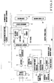
- FIG. 1 shows the circuit arrangement according to an embodiment of the present invention.
- a scanning head 1 serving as an image pickup means comprises an optical system such as a lens 1a and a CCD line sensor 1b for converting an image focused through the optical system into a corresponding electrical signal.
- the scanning head 1 images the resultant printed matter.
- a feed screw 101 is rotated through a motor 100 to change the position (image pickup position) of the scanning head 1, as shown in Fig. 2.
- a signal processing circuit 2 surrounded by an alternate long and short dashed line comprises a reference memory 6 for receiving and storing reference image data, a test memory 7 for receiving and storing test image data, a memory controller 8, a difference circuit 9, a comparator 10, a correction circuit 11, an amplifier 12, an A/D converter 13, and a set value memory 19.
- the signal processing circuit 2 is controlled by a control timing signal and a reference value memory signal.
- the control timing signal is an output signal from a detection/control timing generator 14 and comprises a reference signal as a pulse signal rising every revolution of a plate cylinder (not shown) and a clock pulse as a read/write pulse signal rising every revolution of the plate cylinder through a predetermined angle.
- the control timing signal is supplied to the memory controller 8 and the correction circuit 11.
- the reference value memory signal is supplied to the memory controller 8 when a switch (not shown) is turned on.
- the detection/control timing generator 14 comprises an up/down counter. The time intervals of a detection timing signal and a printing timing signal which are output signals from the up/down counter are changed in accordance with the rotational speed of a printing press which is detected by a rotary encoder 15 serving as a rotation detecting means.
- a PLL circuit 17 compares a reference clock pulse as an output signal from a reference clock generator 16 with the rotational speed pulse signal as the output signal from the rotary encoder 15. The PLL circuit 17 then controls the detection/control timing generator 14 so as to cause the detection timing signal and the control timing signal to correspond to the rotational speed of the printing press.
- a CCD detection timing generator 18 receives the detection timing signal to control the CCD line sensor 1b every revolution of the plate cylinder and causes the signal processing circuit 2 to receive a video signal from the CCD line sensor 1b.
- the read timing of the video signal from the CCD line sensor 1b and the signal processing timing of the signal processing circuit 2 are changed to follow the rotational speed of the printing press (i.e., the rotational speed of the plate cylinder) which is detected by the rotary encoder 15.
- Reference numeral 3 denotes a meandering recognition circuit for receiving the reference image data stored in the reference memory 6 and the test image data stored in the test memory 7 to obtain sums P( ⁇ ) and P( ⁇ D ) of density data (output data) of all pixels included in meandering recognition blocks ⁇ and ⁇ D (to be described later) in the reference memory 6 and the test memory 7.
- the meandering recognition circuit 3 also performs a predetermined arithmetic operation to obtain the amount and direction of meandering of a web being printed as a test object, and supplies a scanning head movement command to the motor 100.
- the state of actual printed matter is visually checked during test printing. If the resultant printed matter is determined to be nondefective, the switch is turned on to send a reference value memory signal.
- a detection timing signal representing the reference position and a control timing signal are then output from the detection/control timing generator 14, reference image data from the reference printed matter is loaded in the reference memory 6. This loading operation is performed in accordance with the detection timing signal and the control timing signal, both of which are output from the detection/control timing generator 14 controlled in response to the clock pulse from the rotary encoder 15.
- test image data obtained from printed matter as a test object i.e., a web being printed as a test object is loaded in the test memory 7 during rotation of the plate cylinder.
- the difference circuit 9 calculates the difference of levels of corresponding density data (output data) represented by the reference image data stored in the reference memory 6 and the test image data stored in the test memory 7 and supplies the resultant level difference to the comparator 10.
- the comparator 10 compares the input level difference with a set value stored in the set value memory 19. If the input level difference is larger than the set value, the comparator 10 outputs a comparison output representing defective printed matter.
- the meandering recognition circuit 3 receives the reference image data stored in the reference memory 6 and the test image data stored in the test memory 7. The meandering recognition circuit 3 calculates the sums P( ⁇ ) and P( ⁇ D ) of the density data (output data) included in the meandering recognition blocks ⁇ and ⁇ D set in the reference memory 6 and the test memory 7. The meandering recognition circuit 3 then performs a predetermined arithmetic operation to obtain the amount and direction of meandering of a web being printed as a test object and outputs a scanning head movement command to the motor 10.
- Fig. 3 is a view showing a relationship between a meandering recognition block ⁇ set for the reference memory 6 and reference image data.
- the meandering recognition block ⁇ is set in the reference memory 6 to satisfy the following six conditions 1 to 6.
- reference image data to be stored in the reference memory 6 is displayed as an image or a color-separated image on a display (not shown).
- the operator sets the meandering recognition block ⁇ to satisfy conditions 1 to 6 above while checking the display screen.
- the amount and direction of meandering are calculated by the meandering recognition circuit 3 as follows.
- the meandering recognition circuit 3 receives reference image data from the reference memory 6 and obtains the sum P( ⁇ ) of the density (output) data of all the pixels included in the meandering recognition block ⁇ .
- a meandering recognition block ⁇ D having the same shape as that of the meandering recognition block ⁇ is set in the test memory 7 at a position corresponding to the meandering recognition block ⁇ set for the reference memory 6.
- the meandering recognition circuit 3 receives the test image data from the test memory 7 to obtain the sum P( ⁇ D ) of the density (output) data of all the pixels included in the meandering recognition block ⁇ D .
- Fig. 4 shows a relationship between the meandering recognition block ⁇ D set for the test memory 7 and the test image data.
- broken lines explicitly indicate reference pattern data stored in the reference memory 6.
- Test pattern data corresponding to this reference pattern data is shifted by la pixels in the left direction (Fig. 4) and stored, as indicated by a solid line in Fig. 4.
- the corresponding positions of the meandering recognition block ⁇ and the meandering recognition block ⁇ D match each other.
- L is the width per pixel on the actual printed matter (i.e., the width of the web in a direction perpendicular to the web traveling direction)
- ⁇ P( ⁇ ) P( ⁇ ) - P( ⁇ D )
- ⁇ P( ⁇ n ) [P(B) - P(A)] ⁇ n
- l is the meandering amount
- the sign of this meandering amount l represents the meandering direction.
- the meandering recognition circuit 3 calculates the difference ⁇ P( ⁇ ) between the sums P( ⁇ ) and P( ⁇ D ) and then a difference ⁇ P( ⁇ n ) between P(B) ⁇ n and P(A) ⁇ n.
- the meandering recognition circuit 3 divides the difference ⁇ P( ⁇ ) by the difference ⁇ P( ⁇ n ) to obtain a shift amount la corresponding to the pixels of the test and reference image data.
- the shift amount la is multiplied with L to obtain the web meandering amount l.
- the sign of the meandering amount l represents the meandering direction. If the sign of the meandering amount is positive, the web traveling direction is the left direction. However, if the sign of the meandering amount is negative, the web traveling direction is the right direction.
- the meandering recognition circuit 3 sends a scanning head movement command corresponding to the resultant meandering amount and direction to the motor 100.
- the feed screw 101 is rotated by the designated amount in the designated direction to correct the image pickup position of the scanning head 1.
- the position of the next test image data to be input and stored in the test memory 7 coincides with the position of the reference image data stored in the reference memory 6. The same state as in the non-meandered state of the web can be obtained.
- one meandering block ⁇ for the reference memory 6 and one meandering block ⁇ D for the test memory 7 are set.
- a plurality of meandering blocks may be set for each memory.
- web meandering amounts are obtained using the meandering recognition blocks ⁇ and ⁇ D in the same manner as described above, and the resultant meandering amounts are arithmetically averaged to obtain the final meandering amount and direction.
- the meandering recognition block ⁇ is set in the reference pattern data in the reference memory 6.
- the meandering recognition block ⁇ may be set to include the end of printing paper if this block satisfies conditions 1 to 6 described above.
- a meandering recognition memory independent of the reference memory 6 may be arranged.
- the input test image data is stored in the test memory 7 and is then processed.
- the input test image data may be sequentially processed in real time in an input order without being stored in the test memory 7.
- the image pickup position of the scanning head 1 is corrected in accordance with the meandering amount and direction which are obtained by the meandering recognition circuit 3.
- the read width (i.e., a direction perpendicular to the web traveling direction) of the scanning head 1 is sufficiently larger than the width of the printed matter as the test object, i.e., if the test object sufficiently falls within the read region of the scanning head 1 even upon occurrence of web meandering
- test image data read by the scanning head 1 is shifted by a pixel count closest to a meandering amount in accordance with the meandering amount and direction which are obtained in the meandering recognition circuit 3, and the shifted test image data is stored in the test memory 7.
- the position of the test data stored in the test memory 7 almost coincides with the position of the reference image data stored in the reference memory 6, and almost the same state as in the non-meandered state of the web can be obtained.
- the pixel width is set small enough to effectively perform correction.
- a shift register 8' having a capacity of storing a pixel data array corresponding to the length of the scanning head 1 is used in place of the memory controller 8 shown in Fig. 1. Only central pixel data except for RL pixel data from the left end of the shift register 8' and RR pixel data from the right end thereof are stored in the reference memory 6 and the test memory 7. When a meandering amount and direction are obtained by the meandering recognition circuit 3, test image data to be stored in the test memory 7 is corrected from the test object in accordance with the following procedures.
- the pixel width is set small enough to effectively perform correction.
- the difference ⁇ P( ⁇ ) between the sum P( ⁇ ) of the output data of all the pixels included in the meandering recognition block ⁇ and the sum P( ⁇ D ) of the output data of all the pixels included in the meandering recognition block ⁇ D is obtained.
- the difference ⁇ P( ⁇ n ) between the product of the output P(B) and the pixel count n of the meandering recognition block ⁇ in the traveling direction Y and the product of the output P(A) and the pixel count n is obtained.
- the difference ⁇ P( ⁇ ) is divided by the difference ⁇ P( ⁇ n ) to obtain a quotient.
- the meandering amount and direction are obtained from the absolute value of the quotient and its sign.
- the meandering amount can be measured with a precision of a size smaller than the width L of one pixel.
- the image pickup position of the image pickup means is corrected on the basis of the obtained measuring amount and direction of the web.
- the position of the next test image data coincides with the position of the reference image data stored in the reference memory, and the same state as in the non-meandered state of the web can be obtained.
- the printed matter which can be satisfactorily circulated as a commercial product will not be erroneously determined as defective printed matter.
Landscapes
- Engineering & Computer Science (AREA)
- Multimedia (AREA)
- Signal Processing (AREA)
- Inking, Control Or Cleaning Of Printing Machines (AREA)
- Length Measuring Devices By Optical Means (AREA)
- Controlling Sheets Or Webs (AREA)
- Investigating Materials By The Use Of Optical Means Adapted For Particular Applications (AREA)
Abstract
Description
- The present invention relates to a method and apparatus for recognizing meandering of a printed web as a test object in printed matter test system for comparing test image data obtained by the printed web with prestored reference image data to detect defective printed matter, and a method and apparatus for correcting an image pickup position in this system.
- In recent printing presses, density data (pixel or output data) of each pixel of reference printed matter is input as reference image data using an image processing means having an optical image pickup system, each density data of target printed matter is input as test image data using the same image processing means, and the reference image data is compared with the test image data to automatically detect defective printed matter.
- Defective printed matter test system of this type includes an image pickup means such as a CCD camera or line sensor, a signal processing circuit for processing an electrical signal as an output signal from this image pickup means, and a reference signal generating means for supplying a reference signal to the signal processing circuit to be processed thereby. The levels of density data of corresponding pixels are compared using the reference image data stored in a reference memory and test image data stored in a test memory to determine whether the difference between these two levels is smaller than a predetermined value, thereby determining defective/nondefective printed matter.
- The reference printed matter is nondefective printed matter on which actually printed contents are visually determined to be nondefective upon test printing at the start of printing.
- In this conventional defective printed matter test system, however, when a web as a test object meanders during printing, the positions of the corresponding pixels represented by the reference image data and the test image data are slightly shifted, and this shift is determined to be defective.
- In a general rotary press, the web slowly meanders during printing due to variations in tension. For this reason, the positions of the corresponding pixels represented by the reference image data and the test image data are gradually shifted from each other. The difference between the levels of the reference image data and the test image data is then gradually increased. Although the resultant printed matter can be sufficiently circulated as commercial printed matter, it is determined to be defective, resulting in inconvenience.
- It is an object of the present invention to provide printed matter test system which inhibits to determine that printed matter which can be satisfactorily circulated as commercial printed matter is defective printed matter even if a web meanders.
- In order to achieve the above object according to an aspect of the present invention, there is provided a method of recognizing meandering of a web in printed matter test system for causing a reference memory to store output data of each pixel of reference printed matter as reference image data, inputting, as test image data, output data of each pixel of printed matter as a test object obtained by printing information on the web, and comparing the reference image data with the test image data, thereby detecting defective printed matter, comprising the steps of, setting, with respect to the reference image data, one side 1A of a rectangular meandering recognition block Φ to be parallel to a printing traveling direction Y at a position where mA1 pixels of an output P(A) are located on one side of the one side 1A and mA2 pixels of the output P(A) are located on the other side thereof, and setting an opposite side 1B of the one side 1A of the meandering recognition block Φ to be parallel to the printing traveling direction Y at a position where mB1 pixels of an output P(B) are located on one side of the opposite side 1B and mB2 pixels are located on the other side of the opposite side 1B, setting, with respect to the test image data, a meandering recognition block ΦD having the same shape as that of the meandering recognition block Φ at a position corresponding to the meandering recognition block Φ set with respect to the reference image data, calculating a difference ΔP(Φ) between a sum P(Φ) of output data of all pixels included in the meandering recognition block Φ and a sum P(ΦD) of output data of all pixels included in the meandering recognition block ΦD, calculating a difference ΔP(Φn) between a product of the output P(B) and a pixel count n of the meandering recognition block Φ in the traveling direction Y and a product of the output P(A) and the pixel count n, and obtaining a meandering amount and a meandering direction of the web on the basis of an absolute value and a sign of a quotient obtained by dividing the difference ΔP(Φ) by the difference ΔP(Φn).
- In order to achieve the above object according to another aspect of the present invention, there is provided an apparatus for recognizing meandering of a web in printed matter test system for causing a reference memory to store output data of each pixel of reference printed matter as reference image data, inputting, as test image data, output data of each pixel of printed matter as a test object obtained by printing information on the web, and comparing the reference image data with the test image data, thereby detecting defective printed matter, comprising a rectangular meandering recognition block Φ set with respect to the reference image data such that one side 1A of the rectangular meandering recognition block Φ is set parallel to a printing traveling direction Y at a position where mA1 pixels of an output P(A) are located on one side of the one side 1A and mA2 pixels of the output P(A) are located on the other side thereof, and such that an opposite side 1B of the one side 1A of the meandering recognition block Φ is set parallel to the printing traveling direction Y at a position where mB1 pixels of an output P(B) are located on one side of the opposite side 1B and mB2 pixels are located on the other side of the opposite side 1B, a meandering recognition block ΦD having the same shape as that of the meandering recognition block Φ and set with respect to the test image data at a position corresponding to the meandering recognition block Φ set with respect to the reference image data, and meandering recognizing means for calculating a difference ΔP(Φ) between a sum P(Φ) of output data of all pixels included in the meandering recognition block Φ and a sum P(ΦD) of output data of all pixels included in the meandering recognition block ΦD, calculating a difference ΔP(Φn) between a product of the output P(B) and a pixel count n of the meandering recognition block Φ in the traveling direction Y and a product of the output P(A) and the pixel count n, and obtaining a meandering amount and a meandering direction of the web on the basis of an absolute value and a sign of a quotient obtained by dividing the difference ΔP(Φ) by the difference ΔP(Φn).
- According to the present invention, using the difference ΔP(Φ) between the sum P(Φ) of the output data of all the pixels included in the meandering recognition block Φ and the sum P(ΦD) of the output data of all the pixels included in the meandering recognition block ΦD, the amount of change in the sum P(ΦD) with respect to the sum P(Φ), which is caused by storage of the test image data shifted from the reference image data in the test memory, is obtained. For example, if test image data is stored in the test memory upon being shifted from the corresponding reference image data by one pixel in one direction due to web meandering, the sum P(ΦD) of the output data of all the pixels included in the meandering recognition block ΦD is decreased from the sum P(Φ) by P(A)·n and increased from the sum P(Φ) by P(B)·n. That is, if P(B) is larger than P(A), the sum P(ΦD) is increased by

- According to the present invention, the image pickup position of the image pickup means for picking up a test object as an image can be corrected on the basis of the resultant web meandering amount and its direction. By this correction of the image pickup position, the position represented by the next test image data is matched with that represented by the reference image data stored in the reference memory. Therefore, the same state as in a non-meandered state of the web can be obtained.
-
- Fig. 1 is a block diagram showing the circuit arrangement according to an embodiment of the present invention;
- Fig. 2 is a view showing the main part of a drive mechanism for shifting the position (image pickup position) of a scanning head;
- Fig. 3 is a view showing a relationship between a meandering recognition block Φ set for a reference memory and reference image data;
- Fig. 4 is a view showing a relationship between a meandering recognition block ΦD set for a test memory and rest image data; and
- Fig. 5 is a block diagram showing the main part of an arrangement for correcting test image data stored in the test memory in accordance with the meandering amount and its direction.
- The present invention will be described in detail with reference to a preferred embodiment in conjunction with the accompanying drawings.
- Fig. 1 shows the circuit arrangement according to an embodiment of the present invention. A scanning head 1 serving as an image pickup means comprises an optical system such as a lens 1a and a
CCD line sensor 1b for converting an image focused through the optical system into a corresponding electrical signal. The scanning head 1 images the resultant printed matter. Afeed screw 101 is rotated through amotor 100 to change the position (image pickup position) of the scanning head 1, as shown in Fig. 2. - Referring to Fig. 1, a signal processing circuit 2 surrounded by an alternate long and short dashed line comprises a
reference memory 6 for receiving and storing reference image data, atest memory 7 for receiving and storing test image data, amemory controller 8, adifference circuit 9, acomparator 10, acorrection circuit 11, anamplifier 12, an A/D converter 13, and aset value memory 19. - The signal processing circuit 2 is controlled by a control timing signal and a reference value memory signal. The control timing signal is an output signal from a detection/
control timing generator 14 and comprises a reference signal as a pulse signal rising every revolution of a plate cylinder (not shown) and a clock pulse as a read/write pulse signal rising every revolution of the plate cylinder through a predetermined angle. The control timing signal is supplied to thememory controller 8 and thecorrection circuit 11. The reference value memory signal is supplied to thememory controller 8 when a switch (not shown) is turned on. - The detection/
control timing generator 14 comprises an up/down counter. The time intervals of a detection timing signal and a printing timing signal which are output signals from the up/down counter are changed in accordance with the rotational speed of a printing press which is detected by arotary encoder 15 serving as a rotation detecting means. At this time, aPLL circuit 17 compares a reference clock pulse as an output signal from areference clock generator 16 with the rotational speed pulse signal as the output signal from therotary encoder 15. ThePLL circuit 17 then controls the detection/control timing generator 14 so as to cause the detection timing signal and the control timing signal to correspond to the rotational speed of the printing press. A CCDdetection timing generator 18 receives the detection timing signal to control theCCD line sensor 1b every revolution of the plate cylinder and causes the signal processing circuit 2 to receive a video signal from theCCD line sensor 1b. - In this embodiment, the read timing of the video signal from the
CCD line sensor 1b and the signal processing timing of the signal processing circuit 2 are changed to follow the rotational speed of the printing press (i.e., the rotational speed of the plate cylinder) which is detected by therotary encoder 15. -
Reference numeral 3 denotes a meandering recognition circuit for receiving the reference image data stored in thereference memory 6 and the test image data stored in thetest memory 7 to obtain sums P(Φ) and P(ΦD) of density data (output data) of all pixels included in meandering recognition blocks Φ and ΦD (to be described later) in thereference memory 6 and thetest memory 7. Themeandering recognition circuit 3 also performs a predetermined arithmetic operation to obtain the amount and direction of meandering of a web being printed as a test object, and supplies a scanning head movement command to themotor 100. - Defective printed matter test operation in this apparatus, i.e., the basic function thereof will be described below.
- At the start of printing, the state of actual printed matter is visually checked during test printing. If the resultant printed matter is determined to be nondefective, the switch is turned on to send a reference value memory signal. When a detection timing signal representing the reference position and a control timing signal are then output from the detection/
control timing generator 14, reference image data from the reference printed matter is loaded in thereference memory 6. This loading operation is performed in accordance with the detection timing signal and the control timing signal, both of which are output from the detection/control timing generator 14 controlled in response to the clock pulse from therotary encoder 15. - After the reference image data is stored in the
reference memory 6, as described above, test image data obtained from printed matter as a test object, i.e., a web being printed as a test object is loaded in thetest memory 7 during rotation of the plate cylinder. - The
difference circuit 9 calculates the difference of levels of corresponding density data (output data) represented by the reference image data stored in thereference memory 6 and the test image data stored in thetest memory 7 and supplies the resultant level difference to thecomparator 10. Thecomparator 10 compares the input level difference with a set value stored in theset value memory 19. If the input level difference is larger than the set value, thecomparator 10 outputs a comparison output representing defective printed matter. - An image pickup position correction operation (additional function), unique to this embodiment, performed simultaneously with the above defective printed matter test operation (basic function) will be described together with the function of the
meandering recognition circuit 3. - The
meandering recognition circuit 3 receives the reference image data stored in thereference memory 6 and the test image data stored in thetest memory 7. Themeandering recognition circuit 3 calculates the sums P(Φ) and P(ΦD) of the density data (output data) included in the meandering recognition blocks Φ and ΦD set in thereference memory 6 and thetest memory 7. Themeandering recognition circuit 3 then performs a predetermined arithmetic operation to obtain the amount and direction of meandering of a web being printed as a test object and outputs a scanning head movement command to themotor 10. - The meandering recognition block Φ for the
reference memory 6 is automatically or manually preset to satisfy the conditions to be described below. Fig. 3 is a view showing a relationship between a meandering recognition block Φ set for thereference memory 6 and reference image data. - The meandering recognition block Φ is set in the
reference memory 6 to satisfy the following six conditions ① to ⑥. - ① The shape of the meandering recognition block Φ is rectangular, and two opposite sides 1A and 1B of the block are parallel to a traveling direction (web traveling direction) Y in printing.
- ② One side 1A of the meandering recognition block Φ is set at a position where mA1 pixels having the same density (output) P(A) are set on one side and mA2 pixels having the same density (output) P(A) are set on the other side.
- ③ One side 1B of the meandering recognition block Φ is located at a position where mB1 pixels having the same density (output) P(B) are set on one side and mB2 pixels having the same density (output) P(B) are set on the other side.
- ④ A difference between the density (output) P(A) of a portion near the side 1A of the meandering recognition block Φ and the density (output) P(B) of a portion near the side 1B thereof is sufficiently large.
- ⑤ The lengths of the pixels mA1, mA2, mB1, and mB2 are much larger than an expected length of a positional shift of the test image data which is caused by meandering.
- ⑥ The meandering recognition block Φ is a set of pixels, and the length of each of the sides 1A and 1B (depth of the meandering recognition block Φ) corresponds to n (n = 1 or more) pixels.
- When the meandering recognition block Φ is to be manually set, reference image data to be stored in the
reference memory 6 is displayed as an image or a color-separated image on a display (not shown). The operator sets the meandering recognition block Φ to satisfy conditions ① to ⑥ above while checking the display screen. - The amount and direction of meandering are calculated by the meandering
recognition circuit 3 as follows. - The meandering
recognition circuit 3 receives reference image data from thereference memory 6 and obtains the sum P(Φ) of the density (output) data of all the pixels included in the meandering recognition block Φ. A meandering recognition block ΦD having the same shape as that of the meandering recognition block Φ is set in thetest memory 7 at a position corresponding to the meandering recognition block Φ set for thereference memory 6. The meanderingrecognition circuit 3 receives the test image data from thetest memory 7 to obtain the sum P(ΦD) of the density (output) data of all the pixels included in the meandering recognition block ΦD. - Fig. 4 shows a relationship between the meandering recognition block ΦD set for the
test memory 7 and the test image data. Referring to Fig. 4, broken lines explicitly indicate reference pattern data stored in thereference memory 6. Test pattern data corresponding to this reference pattern data is shifted by ℓa pixels in the left direction (Fig. 4) and stored, as indicated by a solid line in Fig. 4. However, the corresponding positions of the meandering recognition block Φ and the meandering recognition block ΦD match each other. - The meandering
recognition circuit 3 substitutes the resultant sums P(Φ) and P(ΦD) into equation (1) to obtain the amount and direction of meandering of a web being printed as a test object:

In equation (1), L is the width per pixel on the actual printed matter (i.e., the width of the web in a direction perpendicular to the web traveling direction),
- The meandering
recognition circuit 3 calculates the difference ΔP(Φ) between the sums P(Φ) and P(ΦD) and then a difference ΔP(Φn) between P(B)·n and P(A)·n. The meanderingrecognition circuit 3 divides the difference ΔP(Φ) by the difference ΔP(Φn) to obtain a shift amount ℓa corresponding to the pixels of the test and reference image data. The shift amount ℓa is multiplied with L to obtain the web meandering amount ℓ. At this time, the sign of the meandering amount ℓ represents the meandering direction. If the sign of the meandering amount is positive, the web traveling direction is the left direction. However, if the sign of the meandering amount is negative, the web traveling direction is the right direction. - For example, if the original test image data is shifted by one pixel on one side (in the left direction in Fig. 4) due to web meandering in the left direction with respect to the web traveling direction, and the shifted data is stored in the
test memory 7, the sum P(ΦD) of the density (output) data of all the pixels included in the meandering recognition block ΦD is reduced by P(A)·n and increased by P(B)·n with respect to the sum P(Φ). If P(B) is larger than P(A), the sum P(ΦD) is increased by

- The meandering
recognition circuit 3 sends a scanning head movement command corresponding to the resultant meandering amount and direction to themotor 100. Thefeed screw 101 is rotated by the designated amount in the designated direction to correct the image pickup position of the scanning head 1. By this correction of the image pickup position, the position of the next test image data to be input and stored in thetest memory 7 coincides with the position of the reference image data stored in thereference memory 6. The same state as in the non-meandered state of the web can be obtained. - In the above embodiment, one meandering block Φ for the
reference memory 6 and one meandering block ΦD for thetest memory 7 are set. However, a plurality of meandering blocks may be set for each memory. In this case, web meandering amounts are obtained using the meandering recognition blocks Φ and ΦD in the same manner as described above, and the resultant meandering amounts are arithmetically averaged to obtain the final meandering amount and direction. - In the above embodiment, the meandering recognition block Φ is set in the reference pattern data in the
reference memory 6. However, the meandering recognition block Φ may be set to include the end of printing paper if this block satisfies conditions ① to ⑥ described above. Alternatively, a meandering recognition memory independent of thereference memory 6 may be arranged. - In the above embodiment, the input test image data is stored in the
test memory 7 and is then processed. However, the input test image data may be sequentially processed in real time in an input order without being stored in thetest memory 7. - In the above embodiment, the image pickup position of the scanning head 1 is corrected in accordance with the meandering amount and direction which are obtained by the meandering
recognition circuit 3. However, if the read width (i.e., a direction perpendicular to the web traveling direction) of the scanning head 1 is sufficiently larger than the width of the printed matter as the test object, i.e., if the test object sufficiently falls within the read region of the scanning head 1 even upon occurrence of web meandering, test image data read by the scanning head 1 is shifted by a pixel count closest to a meandering amount in accordance with the meandering amount and direction which are obtained in the meanderingrecognition circuit 3, and the shifted test image data is stored in thetest memory 7. Therefore, the position of the test data stored in thetest memory 7 almost coincides with the position of the reference image data stored in thereference memory 6, and almost the same state as in the non-meandered state of the web can be obtained. In this case, the pixel width is set small enough to effectively perform correction. - In Fig. 5, a shift register 8' having a capacity of storing a pixel data array corresponding to the length of the scanning head 1 is used in place of the
memory controller 8 shown in Fig. 1. Only central pixel data except for RL pixel data from the left end of the shift register 8' and RR pixel data from the right end thereof are stored in thereference memory 6 and thetest memory 7. When a meandering amount and direction are obtained by the meanderingrecognition circuit 3, test image data to be stored in thetest memory 7 is corrected from the test object in accordance with the following procedures. - ① One pixel data array of the scanning head 1 is stored in the shift register 8'.
- ② A value K is set so that K pixels each having a width L have a value closest to the meandering amount ℓ.
- ③ Data in the shift register 8' is shifted by K pixels in the meandering direction.
- In this case, the pixel width is set small enough to effectively perform correction.
- As has been described above, according to the present invention, the difference ΔP(Φ) between the sum P(Φ) of the output data of all the pixels included in the meandering recognition block Φ and the sum P(ΦD) of the output data of all the pixels included in the meandering recognition block ΦD is obtained. The difference ΔP(Φn) between the product of the output P(B) and the pixel count n of the meandering recognition block Φ in the traveling direction Y and the product of the output P(A) and the pixel count n is obtained. The difference ΔP(Φ) is divided by the difference ΔP(Φn) to obtain a quotient. The meandering amount and direction are obtained from the absolute value of the quotient and its sign. For this reason, the meandering amount can be measured with a precision of a size smaller than the width L of one pixel. At the same time, the image pickup position of the image pickup means is corrected on the basis of the obtained measuring amount and direction of the web. The position of the next test image data coincides with the position of the reference image data stored in the reference memory, and the same state as in the non-meandered state of the web can be obtained. The printed matter which can be satisfactorily circulated as a commercial product will not be erroneously determined as defective printed matter.
Claims (4)
- A method of recognizing meandering of a web in printed matter test system for causing a reference memory to store output data of each pixel of reference printed matter as reference image data, inputting, as test image data, output data of each pixel of printed matter as a test object obtained by printing information on said web, and comparing the reference image data with the test image data, thereby detecting defective printed matter, characterized by comprising the steps of:
setting, with respect to the reference image data, one side 1A of a rectangular meandering recognition block Φ to be parallel to a printing traveling direction Y at a position where mA1 pixels of an output P(A) are located on one side of said one side 1A and mA2 pixels of the output P(A) are located on the other side thereof, and setting an opposite side 1B of said one side 1A of said meandering recognition block Φ to be parallel to the printing traveling direction Y at a position where mB1 pixels of an output P(B) are located on one side of said opposite side 1B and mB2 pixels are located on the other side of said opposite side 1B;
setting, with respect to the test image data, a meandering recognition block ΦD having the same shape as that of said meandering recognition block Φ at a position corresponding to the meandering recognition block Φ set with respect to the reference image data;
calculating a difference ΔP(Φ) between a sum P(Φ) of output data of all pixels included in the meandering recognition block Φ and a sum P(ΦD) of output data of all pixels included in the meandering recognition block ΦD;
calculating a difference ΔP(Φn) between a product of the output P(B) and a pixel count n of said meandering recognition block Φ in the traveling direction Y and a product of the output P(A) and the pixel count n; and
obtaining a meandering amount and a meandering direction of said web on the basis of an absolute value and a sign of a quotient obtained by dividing the difference ΔP(Φ) by the difference ΔP(Φn). - An apparatus for recognizing meandering of a web in printed matter test system for causing a reference memory to store output data of each pixel of reference printed matter as reference image data, inputting, as test image data, output data of each pixel of printed matter as a test object obtained by printing information on said web, and comparing the reference image data with the test image data, thereby detecting defective printed matter, characterized by comprising:
a rectangular meandering recognition block Φ set with respect to the reference image data such that one side 1A of the rectangular meandering recognition block Φ is set parallel to a printing traveling direction Y at a position where mA1 pixels of an output P(A) are located on one side of said one side 1A and mA2 pixels of the output P(A) are located on the other side thereof, and such that an opposite side 1B of said one side 1A of said meandering recognition block Φ is set parallel to the printing traveling direction Y at a position where mB1 pixels of an output P(B) are located on one side of said opposite side 1B and mB2 pixels are located on the other side of said opposite side 1B;
a meandering recognition block ΦD having the same shape as that of said meandering recognition block Φ and set with respect to the test image data at a position corresponding to the meandering recognition block Φ set with respect to the reference image data; and
meandering recognizing means (3) for calculating a difference ΔP(Φ) between a sum P(Φ) of output data of all pixels included in the meandering recognition block Φ and a sum P(ΦD) of output data of all pixels included in the meandering recognition block ΦD, calculating a difference ΔP(Φn) between a product of the output P(B) and a pixel count n of said meandering recognition block Φ in the traveling direction Y and a product of the output P(A) and the pixel count n, and obtaining a meandering amount and a meandering direction of said web on the basis of an absolute value and a sign of a quotient obtained by dividing the difference ΔP(Φ) by the difference ΔP(Φn). - A method of correcting an image pickup position in printed matter test system for causing a reference memory to store output data of each pixel of reference printed matter as reference image data, inputting, as test image data, output data of each pixel of printed matter as a test object obtained by printing information on a web, and comparing the reference image data with the test image data, thereby detecting defective printed matter, characterized by comprising the steps of:
obtaining a meandering amount and a meandering direction of said web; and
correcting the image pickup position of image pickup means for imaging the test object on the basis of the meandering amount and meandering direction of said web. - An apparatus for correcting an image pickup position in printed matter test system for causing a reference memory to store output data of each pixel of reference printed matter as reference image data, inputting, as test image data, output data of each pixel of printed matter as a test object obtained by printing information on a web, and comparing the reference image data with the test image data, thereby detecting defective printed matter, characterized by comprising:
meandering recognizing means (3) for obtaining a meandering amount and a meandering direction of said web; and
image pickup position correcting means (100, 101) for correcting the image pickup position of image pickup means for imaging the test object on the basis of the meandering amount and meandering direction of said web obtained by said meandering recognizing means.
Applications Claiming Priority (2)
| Application Number | Priority Date | Filing Date | Title |
|---|---|---|---|
| JP250390/92 | 1992-08-27 | ||
| JP4250390A JPH0671864A (en) | 1992-08-27 | 1992-08-27 | Recognition method and device of meandering of web for printed matter inspection device, and image pickup position correction method and device for printed matter inspection device |
Publications (2)
| Publication Number | Publication Date |
|---|---|
| EP0584637A2 true EP0584637A2 (en) | 1994-03-02 |
| EP0584637A3 EP0584637A3 (en) | 1994-03-16 |
Family
ID=17207204
Family Applications (1)
| Application Number | Title | Priority Date | Filing Date |
|---|---|---|---|
| EP19930112795 Withdrawn EP0584637A3 (en) | 1992-08-27 | 1993-08-10 | Method and apparatus for recognizing meandering in printed matter test system and method and apparatus for correcting image pickup position in this system |
Country Status (2)
| Country | Link |
|---|---|
| EP (1) | EP0584637A3 (en) |
| JP (1) | JPH0671864A (en) |
Cited By (3)
| Publication number | Priority date | Publication date | Assignee | Title |
|---|---|---|---|---|
| US7797133B2 (en) | 2008-09-10 | 2010-09-14 | 3M Innovative Properties Company | Multi-roller registered repeat defect detection of a web process line |
| US7974459B2 (en) | 2004-04-19 | 2011-07-05 | 3M Innovative Properties Company | Apparatus and method for the automated marking of defects on webs of material |
| US8175739B2 (en) | 2007-07-26 | 2012-05-08 | 3M Innovative Properties Company | Multi-unit process spatial synchronization |
Citations (8)
| Publication number | Priority date | Publication date | Assignee | Title |
|---|---|---|---|---|
| JPS6336664A (en) * | 1986-07-31 | 1988-02-17 | Canon Inc | Wark information detector |
| JPS63111057A (en) * | 1986-10-29 | 1988-05-16 | Toppan Printing Co Ltd | Printing quality inspection device |
| US4806034A (en) * | 1988-02-10 | 1989-02-21 | Polaroid Corporation | Write head controller with grid synchronization |
| JPH03221456A (en) * | 1990-01-29 | 1991-09-30 | Canon Inc | Ink jet recorder |
| JPH0450992A (en) * | 1990-06-15 | 1992-02-19 | Hitachi Koki Co Ltd | Controller for correcting meandering of belt |
| EP0477037A2 (en) * | 1990-09-21 | 1992-03-25 | Canon Kabushiki Kaisha | A print evaluation apparatus |
| JPH04128103A (en) * | 1990-09-17 | 1992-04-28 | Iwaguro Seisakusho:Kk | Wrapping material for packaging and packaging machine |
| EP0533306A2 (en) * | 1991-09-19 | 1993-03-24 | Komori Corporation | Method and apparatus for recognizing meandering of web |
-
1992
- 1992-08-27 JP JP4250390A patent/JPH0671864A/en active Pending
-
1993
- 1993-08-10 EP EP19930112795 patent/EP0584637A3/en not_active Withdrawn
Patent Citations (8)
| Publication number | Priority date | Publication date | Assignee | Title |
|---|---|---|---|---|
| JPS6336664A (en) * | 1986-07-31 | 1988-02-17 | Canon Inc | Wark information detector |
| JPS63111057A (en) * | 1986-10-29 | 1988-05-16 | Toppan Printing Co Ltd | Printing quality inspection device |
| US4806034A (en) * | 1988-02-10 | 1989-02-21 | Polaroid Corporation | Write head controller with grid synchronization |
| JPH03221456A (en) * | 1990-01-29 | 1991-09-30 | Canon Inc | Ink jet recorder |
| JPH0450992A (en) * | 1990-06-15 | 1992-02-19 | Hitachi Koki Co Ltd | Controller for correcting meandering of belt |
| JPH04128103A (en) * | 1990-09-17 | 1992-04-28 | Iwaguro Seisakusho:Kk | Wrapping material for packaging and packaging machine |
| EP0477037A2 (en) * | 1990-09-21 | 1992-03-25 | Canon Kabushiki Kaisha | A print evaluation apparatus |
| EP0533306A2 (en) * | 1991-09-19 | 1993-03-24 | Komori Corporation | Method and apparatus for recognizing meandering of web |
Non-Patent Citations (5)
| Title |
|---|
| PATENT ABSTRACTS OF JAPAN vol. 012, no. 250 (E-633)14 July 1988 & JP-A-63 036 664 (CANON) 17 February 1988 * |
| PATENT ABSTRACTS OF JAPAN vol. 012, no. 352 (M-744)21 September 1988 & JP-A-63 111 057 (TOPPAN PRINTING CO) 16 May 1988 * |
| PATENT ABSTRACTS OF JAPAN vol. 015, no. 505 (M-1194)20 December 1991 & JP-A-03 221 456 (CANON) 30 September 1991 * |
| PATENT ABSTRACTS OF JAPAN vol. 016, no. 237 (P-1362)29 May 1992 & JP-A-04 050 992 (HITACHI KOKI CO) 19 February 1992 * |
| PATENT ABSTRACTS OF JAPAN vol. 016, no. 388 (M-1297)18 August 1992 & JP-A-04 128 103 (IWAGURO SEISAKUSHIYO) 28 April 1992 * |
Cited By (4)
| Publication number | Priority date | Publication date | Assignee | Title |
|---|---|---|---|---|
| US7974459B2 (en) | 2004-04-19 | 2011-07-05 | 3M Innovative Properties Company | Apparatus and method for the automated marking of defects on webs of material |
| US8238646B2 (en) | 2004-04-19 | 2012-08-07 | 3M Innovative Properties Company | Apparatus and method for the automated marking of defects on webs of material |
| US8175739B2 (en) | 2007-07-26 | 2012-05-08 | 3M Innovative Properties Company | Multi-unit process spatial synchronization |
| US7797133B2 (en) | 2008-09-10 | 2010-09-14 | 3M Innovative Properties Company | Multi-roller registered repeat defect detection of a web process line |
Also Published As
| Publication number | Publication date |
|---|---|
| EP0584637A3 (en) | 1994-03-16 |
| JPH0671864A (en) | 1994-03-15 |
Similar Documents
| Publication | Publication Date | Title |
|---|---|---|
| US4554592A (en) | Image forming apparatus | |
| EP0533305B1 (en) | Method and apparatus for detecting defective printed matter in printing press | |
| US4648048A (en) | Apparatus for determining and evaluating color measurement strips on a printed sheet | |
| US5377279A (en) | Method and apparatus for displaying defect in central area of monitor | |
| EP1211885B1 (en) | Color calibration alarm for use in an image-rendering device | |
| US4731668A (en) | Image reading apparatus including means for accurately determining the location of read image information | |
| US5327252A (en) | Print evaluation apparatus | |
| US8238000B2 (en) | Method and apparatus for calibrating a transport scanner and a test original for use with such method | |
| EP0584637A2 (en) | Method and apparatus for recognizing meandering in printed matter test system and method and apparatus for correcting image pickup position in this system | |
| KR890001932B1 (en) | Recorder | |
| JPS6153916B2 (en) | ||
| EP0533306A2 (en) | Method and apparatus for recognizing meandering of web | |
| JPH0147821B2 (en) | ||
| US5440402A (en) | Method and apparatus for recognizing paster portion of web | |
| GB2159623A (en) | Print inspecting method | |
| JP3039704B2 (en) | Printing evaluation method and printing evaluation device | |
| JP2733958B2 (en) | Long sheet defect inspection equipment | |
| JPH06246904A (en) | Method and apparatus for automatically re-inputting reference data | |
| JPH0257772B2 (en) | ||
| JP2996868B2 (en) | Printing paper surface inspection equipment | |
| JPH0573585B2 (en) | ||
| JP3072787B2 (en) | Printing evaluation method and printing evaluation device | |
| JPH0431307B2 (en) | ||
| JP2938561B2 (en) | Method and apparatus for evaluating printed matter | |
| JPH05124179A (en) | Method and apparatus for automatically re-entry reference data |
Legal Events
| Date | Code | Title | Description |
|---|---|---|---|
| PUAI | Public reference made under article 153(3) epc to a published international application that has entered the european phase |
Free format text: ORIGINAL CODE: 0009012 |
|
| PUAL | Search report despatched |
Free format text: ORIGINAL CODE: 0009013 |
|
| 17P | Request for examination filed |
Effective date: 19930810 |
|
| AK | Designated contracting states |
Kind code of ref document: A2 Designated state(s): AT CH DE FR GB IT LI NL SE |
|
| AK | Designated contracting states |
Kind code of ref document: A3 Designated state(s): AT CH DE FR GB IT LI NL SE |
|
| 17Q | First examination report despatched |
Effective date: 19960503 |
|
| STAA | Information on the status of an ep patent application or granted ep patent |
Free format text: STATUS: THE APPLICATION IS DEEMED TO BE WITHDRAWN |
|
| 18D | Application deemed to be withdrawn |
Effective date: 19960914 |