EP0583914B1 - Catalyst-downcomer-tray for chemical process tower - Google Patents
Catalyst-downcomer-tray for chemical process tower Download PDFInfo
- Publication number
- EP0583914B1 EP0583914B1 EP93306144A EP93306144A EP0583914B1 EP 0583914 B1 EP0583914 B1 EP 0583914B1 EP 93306144 A EP93306144 A EP 93306144A EP 93306144 A EP93306144 A EP 93306144A EP 0583914 B1 EP0583914 B1 EP 0583914B1
- Authority
- EP
- European Patent Office
- Prior art keywords
- downcomer
- tray
- liquid
- flow
- vapor
- Prior art date
- Legal status (The legal status is an assumption and is not a legal conclusion. Google has not performed a legal analysis and makes no representation as to the accuracy of the status listed.)
- Expired - Lifetime
Links
Images


Classifications
-
- B—PERFORMING OPERATIONS; TRANSPORTING
- B01—PHYSICAL OR CHEMICAL PROCESSES OR APPARATUS IN GENERAL
- B01D—SEPARATION
- B01D3/00—Distillation or related exchange processes in which liquids are contacted with gaseous media, e.g. stripping
- B01D3/009—Distillation or related exchange processes in which liquids are contacted with gaseous media, e.g. stripping in combination with chemical reactions
-
- B—PERFORMING OPERATIONS; TRANSPORTING
- B01—PHYSICAL OR CHEMICAL PROCESSES OR APPARATUS IN GENERAL
- B01D—SEPARATION
- B01D3/00—Distillation or related exchange processes in which liquids are contacted with gaseous media, e.g. stripping
- B01D3/14—Fractional distillation or use of a fractionation or rectification column
- B01D3/16—Fractionating columns in which vapour bubbles through liquid
- B01D3/18—Fractionating columns in which vapour bubbles through liquid with horizontal bubble plates
- B01D3/20—Bubble caps; Risers for vapour; Discharge pipes for liquid
-
- B—PERFORMING OPERATIONS; TRANSPORTING
- B01—PHYSICAL OR CHEMICAL PROCESSES OR APPARATUS IN GENERAL
- B01D—SEPARATION
- B01D3/00—Distillation or related exchange processes in which liquids are contacted with gaseous media, e.g. stripping
- B01D3/14—Fractional distillation or use of a fractionation or rectification column
- B01D3/16—Fractionating columns in which vapour bubbles through liquid
- B01D3/22—Fractionating columns in which vapour bubbles through liquid with horizontal sieve plates or grids; Construction of sieve plates or grids
-
- B—PERFORMING OPERATIONS; TRANSPORTING
- B01—PHYSICAL OR CHEMICAL PROCESSES OR APPARATUS IN GENERAL
- B01J—CHEMICAL OR PHYSICAL PROCESSES, e.g. CATALYSIS OR COLLOID CHEMISTRY; THEIR RELEVANT APPARATUS
- B01J8/00—Chemical or physical processes in general, conducted in the presence of fluids and solid particles; Apparatus for such processes
- B01J8/02—Chemical or physical processes in general, conducted in the presence of fluids and solid particles; Apparatus for such processes with stationary particles, e.g. in fixed beds
- B01J8/04—Chemical or physical processes in general, conducted in the presence of fluids and solid particles; Apparatus for such processes with stationary particles, e.g. in fixed beds the fluid passing successively through two or more beds
-
- B—PERFORMING OPERATIONS; TRANSPORTING
- B01—PHYSICAL OR CHEMICAL PROCESSES OR APPARATUS IN GENERAL
- B01J—CHEMICAL OR PHYSICAL PROCESSES, e.g. CATALYSIS OR COLLOID CHEMISTRY; THEIR RELEVANT APPARATUS
- B01J2208/00—Processes carried out in the presence of solid particles; Reactors therefor
- B01J2208/00008—Controlling the process
- B01J2208/00017—Controlling the temperature
- B01J2208/00106—Controlling the temperature by indirect heat exchange
- B01J2208/00168—Controlling the temperature by indirect heat exchange with heat exchange elements outside the bed of solid particles
- B01J2208/00247—Reflux columns
-
- B—PERFORMING OPERATIONS; TRANSPORTING
- B01—PHYSICAL OR CHEMICAL PROCESSES OR APPARATUS IN GENERAL
- B01J—CHEMICAL OR PHYSICAL PROCESSES, e.g. CATALYSIS OR COLLOID CHEMISTRY; THEIR RELEVANT APPARATUS
- B01J2208/00—Processes carried out in the presence of solid particles; Reactors therefor
- B01J2208/00008—Controlling the process
- B01J2208/00548—Flow
-
- B—PERFORMING OPERATIONS; TRANSPORTING
- B01—PHYSICAL OR CHEMICAL PROCESSES OR APPARATUS IN GENERAL
- B01J—CHEMICAL OR PHYSICAL PROCESSES, e.g. CATALYSIS OR COLLOID CHEMISTRY; THEIR RELEVANT APPARATUS
- B01J2208/00—Processes carried out in the presence of solid particles; Reactors therefor
- B01J2208/00796—Details of the reactor or of the particulate material
- B01J2208/00884—Means for supporting the bed of particles, e.g. grids, bars, perforated plates
-
- B—PERFORMING OPERATIONS; TRANSPORTING
- B01—PHYSICAL OR CHEMICAL PROCESSES OR APPARATUS IN GENERAL
- B01J—CHEMICAL OR PHYSICAL PROCESSES, e.g. CATALYSIS OR COLLOID CHEMISTRY; THEIR RELEVANT APPARATUS
- B01J2219/00—Chemical, physical or physico-chemical processes in general; Their relevant apparatus
- B01J2219/32—Details relating to packing elements in the form of grids or built-up elements for forming a unit of module inside the apparatus for mass or heat transfer
- B01J2219/324—Composition or microstructure of the elements
- B01J2219/32466—Composition or microstructure of the elements comprising catalytically active material
-
- Y—GENERAL TAGGING OF NEW TECHNOLOGICAL DEVELOPMENTS; GENERAL TAGGING OF CROSS-SECTIONAL TECHNOLOGIES SPANNING OVER SEVERAL SECTIONS OF THE IPC; TECHNICAL SUBJECTS COVERED BY FORMER USPC CROSS-REFERENCE ART COLLECTIONS [XRACs] AND DIGESTS
- Y02—TECHNOLOGIES OR APPLICATIONS FOR MITIGATION OR ADAPTATION AGAINST CLIMATE CHANGE
- Y02P—CLIMATE CHANGE MITIGATION TECHNOLOGIES IN THE PRODUCTION OR PROCESSING OF GOODS
- Y02P20/00—Technologies relating to chemical industry
- Y02P20/10—Process efficiency
-
- Y—GENERAL TAGGING OF NEW TECHNOLOGICAL DEVELOPMENTS; GENERAL TAGGING OF CROSS-SECTIONAL TECHNOLOGIES SPANNING OVER SEVERAL SECTIONS OF THE IPC; TECHNICAL SUBJECTS COVERED BY FORMER USPC CROSS-REFERENCE ART COLLECTIONS [XRACs] AND DIGESTS
- Y10—TECHNICAL SUBJECTS COVERED BY FORMER USPC
- Y10S—TECHNICAL SUBJECTS COVERED BY FORMER USPC CROSS-REFERENCE ART COLLECTIONS [XRACs] AND DIGESTS
- Y10S203/00—Distillation: processes, separatory
- Y10S203/06—Reactor-distillation
Definitions
- the present invention pertains to gas-liquid contacting trays of chemical process towers and, more particularly, to an improved downcomer-tray assembly therefor.
- Distillation columns are utilized to separate selected components from a multicomponent stream.
- gas-liquid contact columns utilize either trays, packing or combinations thereof.
- bubble caps By sieve and valve trays in most tray column designs, and the popularity of packed columns, either random (dumped) or structured packing have been utilized in combination with the trays in order to effect improved separation of the components in the stream.
- vapor and liquid contact devices such as trays
- trays are characterized by relatively high pressure drop and relatively high liquid hold-up.
- Another type of vapor and liquid contact apparatus namely structured high efficiency packing
- Such packing is energy efficient because it has low pressure drop and low liquid hold-up.
- these very properties at times make columns equipped with structured packing difficult to operate in a stable, consistent manner.
- many applications simply require the use of trays.
- Fractionation column trays come in two configurations: cross-flow and counter flow.
- the trays generally consist of a solid tray or deck having a plurality of apertures and are installed on support rings within the tower.
- vapor ascends through the apertures and contacts the liquid moving across the tray; through the "active" area thereof; in this area liquid and vapor mix and fractionation occurs.
- the liquid is directed onto the tray by means of a vertical channel from the tray above. This channel is referred to as the Inlet Downcomer.
- the liquid moves across the tray and exits through a similar channel referred to as the Exit Downcomer.
- Such downcomers are located where there is a sufficient volume of liquid to effect a liquid-phase, chemical reaction, in the case of catalytic distillation.
- the location of the downcomers determine the flow pattern of the liquid. If there are two Inlet Downcomers and the liquid is split into two streams over each tray, it is called a two pass tray. If there is only one Inlet and one Outlet Downcomer on opposite sides of the tray, it is called a single pass tray. For two or more passes, the tray is often referred to as a Multipass Tray. The number of passes generally increases as the required (design) liquid rate increases. It is the active area of the tray, however, which is of critical concern.
- the area under the Inlet Downcomer is generally a solid region.
- the downcomers are often sloped.
- the maximum vapor/liquid handling capacity of the tray generally increases with an increase in the active or Bubbling Area.
- the present invention specifically addresses the problem of restricted disengagement of vapor retained in the liquid, or vapors generated within the downcomer or introduced into the downcomer.
- a variation for increasing the Bubbling Area and hence vapor/liquid handling capacity is a Multiple Downcomer (MD) tray.
- MD Multiple Downcomer
- the downcomers do not extend all the way to the tray below but stop short of the tray by a predetermined distance which is limited by a sufficient space to permit disengagement of any vapor retained in the liquid entering the Exit Downcomer.
- the downcomer pattern is rotated 90 degrees between successive trays.
- the bottom of the boxes is solid except for slots that direct the liquid onto the Bubbling Area of the tray below, in between the outlet downcomers of said tray.
- the MD tray falls into the category of Multipass Trays and is usually used for high liquid rates.
- the specifics of the present invention where catalyst media is employed in the downcomers to promote a chemical reaction is also applicable to MD trays.
- concentration-difference between the vapor and the liquid is the driving force to effect mass transfer.
- Said concentration-difference can be effected in many ways; some reducing efficiency. For example, as operating pressure increases, descending liquid begins to absorb vapor as it moves across a tray. This is above that normally associated as dissolved gas as governed by Henry's Law and represents much larger amounts of vapor bubbles that are commingled or "entrained” with the liquid. This vapor is not firmly held and is released within the downcomer, and, in fact, the majority of said vapor must be released, otherwise the downcomer can not accommodate the liquid/vapor mixture and will flood thus preventing successful tower operation.
- This phenomena is generally deemed to occur when operating pressure is such as to produce a vapor density above about 16.0 kg/m (1.0 lbs/cu. ft.) and typically amounts to about 10 to 20% of the vapor by volume.
- Liquid entrainment is, in one sense, a dynamic flow condition. High velocity vapor flow can suspend descending liquid droplets and prevent their effective passage through the underlying froth mixture zone. It is particularly difficult to prevent this problem when the tower applications require high volume vapor flow in a direction virtually opposite to that of high volume, descending liquid flow.
- US-A-4,550,000 assigned to Shell Oil Company teaches apparatus for contacting a liquid with a gas in a relationship between vertically stacked trays in a tower.
- the apertures in a given tray are provided for the passage of gas in a manner less hampered by liquid coming from a discharge means of the next upper tray.
- This is provided by perforated housings secured to the tray deck beneath the downcomers for breaking up the descending liquid flow.
- Such advances improve tray efficiency within the confines of prior art structures.
- US-A-4,543,219 assigned to Nippon Kayaku Kabushiki Kaisha of Tokyo, Japan teaches a baffle tray tower. The operational parameters of high gas-liquid contact efficiency and the need for low pressure loss are set forth.
- a downcomer outlet baffle is therein shown to control the discharge of liquid therefrom.
- the baffle may include either a static seal or dynamic seal.
- the openings from the downcomer are sufficiently small to control discharge and may be larger than the tray perforations and of circular or rectangular shape.
- the transient forces which may disrupt the operation of a downcomer are also more fully elaborated therein. These forces and related vapor-liquid flow problems must be considered for each application in which a downcomer feeds an underlying tray.
- distillation columns A more recent use of distillation columns is for simultaneous or stagewise fractionation in conjunction with a chemical reaction.
- the kinetics of a chemical reaction can be improved by changing the equilibrium of the reactants with the products.
- the mechanical designs seen in US-A-3,629,478 and 3,634,534 illustrate distillation column reactors with catalyst in the downcomers.
- the vapor disengaging space at the entrance to the downcomer could become grossly overloaded causing the entire tower to fail in its intended distillation function.
- One operational consideration is thus venting of the gases generated within the downcomer, as well as those entrained from the tray deck. Such considerations must be addressed when maximizing tower operational efficiency.
- the present invention is directed at a downcomer-tray assembly for a process column in which a downward flow of liquid interacts with an upward flow of vapour, the assembly having a first downcomer for carrying liquid to one side of a first column tray with a central section allowing the upward flow of vapour therethrough and a second downcomer on the other side of the tray for carrying liquid therefrom to a second column tray and thence to a third downcomer disposed beneath the first downcomer.
- the arrangement enables liquid to flow across the trays while interacting with vapour flowing upwardly therethrough.
- the first tray has an active inlet section beneath the first downcomer which is raised relative to the central section thereof, which section has openings for directing vapour into engagement with liquid from the downcomer oriented to control the direction of vapour and liquid flow therefrom across the central section.
- Means are provided in the third downcomer for supporting a catalyst media whereby vapour from such media is vented to the active inlet section of the first tray and directed into engagement with liquid discharged from the first downcomer.
- the catalyst media may be present in bundles or in another alternative, retained in a cage. The invention thus enables vapour from the catalyst media to perform the additional function of affording a horizontal flow vector to the descending liquid upon engagement therewith.
- the downcomers will be constructed for providing a dynamic seal against ascending vapour flow produced from catalyst media in the third downcomer, and they may have a fluid discharge region that is spaced above the active inlet region for establishing a fluid reservoir and uniform discharge thereon.
- such discharge region comprises a plurality of apertures formed thereacross and disposed above the active inlet section in generally parallel spaced relationship thereto.
- it comprises a tapered Venturi area formed thereacross and disposed above the active inlet section in generally parallel spaced relationship thereto. The taper can provide a surface against which a substantially horizontal vapor-flow characteristic is formed.
- the downcomer in the tray assembly is constructed with an angulated body for engaging the ascending vapor flow and enhancing horizontal flow characteristics therefrom.
- the downcomer is constructed with a body portion angulated toward the raised, active inlet region for establishing a vapor flow having substantial horizontal flow characteristics.
- the invention also includes the use of an assembly as mentioned above for mixing vapour with liquid discharged from the downcomer of a process column onto an underlying tray of the type wherein descending liquid mixes with ascending vapour flow through said tray.
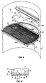
- FIG. 1 there is shown a fragmentary, perspective view of an illustrative packed exchange tower or column with various sections cut away for showing a variety of tower internals and the utilization of one embodiment of the improved catalyst-downcomer-tray assembly of the present invention.
- the exchange column 10 of FIG. 1 comprises a cylindrical tower 12 having a plurality of packing bed layers 14 and trays disposed therein.
- a plurality of manways 16 are likewise constructed for facilitating access to the internal region of the tower 12.
- side stream draw off line 20 liquid side feed line 18, and side stream vapor feed line or reboiler return line 32.
- a reflux return line 34 is provided atop the tower 10.
- liquid 13 is fed into the tower 10 through reflux return line 34 and side stream feed input feed line 18.
- the liquid 13 flows downwardly through the tower and ultimately leaves the tower either at side stream draw off 20, or at bottom stream draw off line 30.
- the liquid 13 is depleted of some material which evaporates from it as it passes through the trays and packing beds, and is enriched or added to by material which condenses into it out of the vapor stream.
- the exchange column 10 is diagrammatically cut in half for purposes of clarity.
- the column 10 includes a vapor outlet in overhead line 26 disposed atop the tower 12 and a lower skirt 28 disposed in the lower region of the tower around bottom stream takeoff line 30 coupled to a reboiler (not shown).
- Reboiler return conduit 32 is shown disposed above the skirt 28 for recycling vapor therein upwardly through the trays and/or packing layers 14.
- Reflux from condensers is provided in the upper tower region 23 through entry conduit 34 wherein reflux is distributed throughout a liquid distributor 36 across upper packing bed 38. It may be seen that the upper packing bed 38 is of the structured packing variety.
- the regions of the exchange column 10 beneath the upper packing bed 38 are shown for the purpose of illustration and include a liquid collector 40 disposed beneath a support grid 41 in support of the upper structured packing 38.
- a liquid distributor 42 adapted for redistributing liquid 13, is likewise disposed there-beneath.
- a second type of distributor 42A is shown below the cut-line 43 and disposed above bed 14.
- the column 10 is presented with cut-line 43 for illustrating the fact that the tower internals arrangement is diagrammatical only and is provided for referencing various component arrays therein.
- a trayed column usually contains a plurality of trays 48 of the type shown herein.
- the trays 48 are valve or sieve trays.
- Such trays comprise plates which are perforated or slotted in construction. The vapor and the liquid engage at or along the tray and, in some assemblies, are permitted to flow through the same openings in a counter-current flow arrangement. Optimally, the vapor and liquid flows reach a level of stability.
- this stability may be achieved with a relatively low flow rate permitting the ascending vapor to mix with the descending liquid.
- no downcomers are used and the vapor and the liquid use the same openings, alternating as the respective pressures change. But such is not the case herein.
- Tray 48 is of conventional design manifesting a conventional perforated, or slotted, surface 50.
- Tray 49 includes a raised inlet section 51 beneath downcomer 53, which downcomer is constructed for securing catalyst media therein.
- the catalyst media 400 cannot, however, be seen in this view of downcomer 53, but can be diagrammatically illustrated in downcomer 69.
- the downcomer 53 is also tapered downwardly, as will be described below.
- the apertures in the inlet section 51 can be simple perforations or directional flow vanes, as will be described below, and are the result of a myriad of critical design considerations including liquid/vapor ratios, liquid cooling, liquid flow/back-mixing, froth height and uniformity, the presence of solids or slurries therein and the requisite need to vent excess pressure in the underlying tray. Corrosion is likewise a consideration of the various elements in the packed towers and the selection of the material, design, and the fabrication of the tower internal is, in many instances, the result of such considerations.
- the anatomy of process columns as shown in FIG. 1 is likewise described in more detail in an article by Gilbert Chen, entitled "Packed Column Internals" appearing in the March 5, 1984 edition of Chemical Engineering , incorporated herein by reference.
- An upper tray 48 comprises a planar panel that is perforated, as shown.
- the lower tray 49 is also of generally planar construction across its central active area 52.
- Liquid 13 travels from tray 48 disposed thereabove down downcomer 53, through catalyst 400 and out bottom section 54.
- Vapor 15 is often generated or trapped in the liquid 13, as indicated by vapor bubbles 15A emitted from catalyst bed 402 shown in the downcomers 69.
- the tapered sections 54 of the downcomers provide clearance angles for vapor flow from the active inlet areas, which clearance angles afford horizontal flow vectors to the vapor vented through raised panels 51 and 71.
- the liquid 13 engages the vented vapor 15 discharged from the raised active panel area 51 beneath the downcomer 53.
- the venting region therebeneath is so labeled. Catalyst generated or entrained gas escaping from the lower downcomer and catalyst media 404 disposed therein and below the venting region is able to ascend directly into and through the panel area 51. Without the raised panel 51, there would be no preferential vapor flow of the gas escaping from the downcomer and it would tend to rise through the conventional active region 52.
- This engagement controls the direction of vented vapor and liquid flow across the central active region 52 of tray 49; the taper of the mitered section 54 imparting a horizontal flow characteristic.
- the raised panel 51 permits any excess vapor pressure to be vented through the panel and into a flow configuration which facilitates proper tower operation rather than creating more problems.
- entraining liquid 13A is induced to drop out due to the flow configuration.
- the remaining ascending vapor 15 passing through the plurality of perforations 59 of said active region 52 may rise vertically to create a froth 61.
- the froth or "foam" is a region of aeration in which the phase of the liquid 13 is continuous.
- an inversion to a gas-continuous regime can result in a "spray" of gas upwardly therethrough. With the downcomer-tray assembly of the present invention, the likelihood of this gas continuous regime is greatly reduced.
- the froth 61 extends with a relatively uniform height, shown in phantom by line 63 across the width of the tray 49 to the opposite end 65 where a weir 67 is established for maintaining the froth height 63.
- the accumulated froth at this point flows over the top of the weir 67 into associated downcomer 69 that carries the froth downwardly into a mitered region 70 where the liquid accumulates and disperses upon active inlet region 71 therebeneath.
- active inlet region 71 is shown herein diagrammatically for purposes of illustration only.
- the area of holes and perforations for a single cross-flow plate establish the active length of the plate and the zone in which the froth 61 is established.
- the present invention would also be applicable to multiple downcomer configurations, wherein the downcomers and raised, active inlet areas may be positioned in intermediate areas of the trays. By increasing the total active area by active inlet areas 51 and 71 greater capacity and efficiency is achieved. It is also the manner of flow of the liquid 13 across the tray 49 which, in the present embodiment, is critical to tray efficiency. A flow diagram of a conventional sieve plate will be discussed below for purposes of illustrating the efficiency afforded by the present invention.
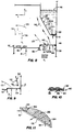
- FIG. 3 there is shown a flow diagram across a conventional sieve plate.
- the prior art sieve plate 72 is illustrated herein as a round tray having a first conventional downcomer for feeding liquid upon a solid, underlying panel 73 and then to the tray 74.
- a second downcomer 74A carries liquid away from the tray.
- a plurality of arrows 75 illustrate the non-uniform flow of liquid 13 across a conventional plate.
- Recirculation cells 76 are shown to be formed on both sides of the plate lateral to the direction of flow. The formation of these retrograde flow areas, or recirculation cells, decreases the efficiency of the tray.
- FIG. 4 there is shown an enlarged, fragmentary perspective view of a downcomer-tray assembly 100 illustrating various flow characteristics.
- the tray 49 as shown herein is constructed for placement in the tower 12 whereby a feeding downcomer 102 having an inclined face 103, can be disposed over an inlet region 104 for providing liquid 13 to tray 49.
- a weir 82 is disposed on the opposite side of tray 49 whereby a second downcomer is disposed for carrying froth 61 and liquid 13 away from the tray 49.
- Liquid 13 spills down upon active inlet panel 104 and over upstanding edge 106 onto the tray 49.
- the liquid 13 flows across the tray in the direction of arrows 83 and 84.
- the flow directions will be induced by vapor flow from panel 104 and will be substantially uniform in accordance with the principles of the present invention and without the backflow problems discussed above.
- Arrows 105 reflect the horizontal flow characteristic of the vapor vented from the underlying tray, which flow characteristic is produced by the panel 104 and the inclined face 103. In this manner, two distinct advantages may be recognized. The absence of back mixing will increase the concentration-difference driving force for mass transfer between the counter-flowing streams.
- the horizontal vapor flow aspect represented by arrows 105 will facilitate the dropping out of liquid droplets entrained in the vapor flow 105. Such entrainment is common in towers with ascending vapor flow, but it is exacerbated with the venting flow arising from the inlet panel 104.
- a sieve type tray is constructed with trapezoidal, or V-shaped, wires 55. It is incorporated into a SCREEN TRAY type sieve tray embodiment.
- SCREEN TRAY is a trademark of the assignee of the present invention and represents the central active area of tray 49 constructed with the array of V-shaped wires 55 disposed in generally parallel spaced relationship.
- the adjacent V-shaped wires 55 are secured by cross members 58 and form a "Venturi" shaped slit 87 between each of the wires resulting in very low energy loss.
- the relative size of the mesh 51 and tray 49 are not to scale and are presented by illustrating the tray assembly.
- Each wire 55 has a trapezoidal outer perimeter surface 56 forming the above defined tapered slit 87.
- Such a tray operates in the froth regime at maximum efficiency over a wide range of conditions. Gas 15 is thus shown rising to engage liquid 13 flowing orthogonal thereto from the downcomer 102 of FIG. 4. The result is a turbulent pattern of gas and liquid engagement effecting efficient mass transfer. Likewise, froth height is maximized, entrainment is minimized and low pressure drop results in reduced downcomer backup.
- the directionalized flow from the raised, active inlet panel 104 provides an enhancement in tray efficiency, with minimum height. It should also be noted that any style of apertures could be incorporated into the active area of tray 49.
- V-shaped wires are shown, bubble cap trays, other slotted openings, perforations, valves (both fixed and moveable) could be used with the present invention.
- FIG. 6 there is shown an enlarged top plan view of the tray 49 of FIG. 4 illustrating additional flow aspects thereof.
- the tray 49 is constructed with a plurality of panel sections. These sections are not shown with aperture detail for purposes of clarity.
- Section 120 comprises an outer panel having an arcuate side wall 121.
- Panel 122 is secured adjacent panel 120 and is comprised of generally rectangular configuration.
- Panel 124 is likewise secured adjacent panel 122 and likewise comprises a generally rectangular configuration.
- Each of the panels 120, 122 and 124 are constructed of the appropriate tray material such as the sieve tray construction shown in FIG. 5. It may be seen that upstanding edge 106 is shown separating the trays 122 and 124 from the raised inlet panel 104.
- Panel 104 in this particular embodiment, is comprised of first and second panel sections 110 and 112 which are welded together across abutting joint 113 in abutting seam 113.
- Each panel 110 and 112 is constructed with louvers 114 facing in selected directions. Louvers 114 of panel 110 are angled to vector vapor flow in the direction of arrow 116. Likewise, louvers 114 and panel 112 are angled to vector vapor flow in the direction of arrow 118. The select vapor and liquid flow then occurs across the panels 120, 122 and 124 to the opposite downcomer.
- a downcomer panel 126 is shown sloped downwardly to a bottom discharge plate 128 in which rectangular apertures 130 are formed in the outermost section thereof. In this manner, the flow path of discharge liquid is maximized across the tray. Maximizing the length of travel of the liquid maximizes the tray efficiency, which aspect is labeled beneath the drawing of FIG. 6.
- FIG. 7 there is shown a side elevational, cross sectional view of the tray 49 of FIG. 6.
- the weir 82 is shown to be constructed of a generally L-shaped member adjacent the downcomer 102.
- the downcomer 102 on the left side of FIG. 7 is constructed with first sloping wall 126 which engages a second angulated sloping wall region 132.
- the angulated wall region 132 has a mitered section 134 which permits egress of ascending vapor from the raised panel therebeneath with a horizontal flow vector.
- An angulated downcomer may be provided in this vicinity for effecting vapor passage from the raised inlet panel.
- FIG. 7 illustrates the orientation of this preferential vapor flow area immediately above the downcomer disposed therebelow.
- Gas entrained in liquid which flows into the downcomer and is released must find a region of escape. The same is true for vapor generated from catalyst media secured in such downcomers, as discussed in more detail below.
- the escaping vapor is illustrated rising up to and through the panel 104 where it is preferentially vented.
- a support beam 136 is shown to form a chamber beneath the panel 104.
- Apertures 137 are formed through the side wall of beam 136 to serve as vapor flow equalization holes. If excessive vapor fills the chamber beneath panel 104 it can escape outwardly through flow equalization holes 137.
- FIG. 8 there is shown an enlarged, side elevational cross sectional view of the downcomer 102 and raised inlet panel 104 of FIG. 4.
- the downcomer 102 is seen to incorporate the select tapered wall region 103 which may be used to increase vapor flow efficiency as discussed above.
- the slots 130 are formed in the lower region thereof for discharging liquid 13 directly onto panel 104 into engagement with ascending vapor 15.
- the inlet panel 104 of this particular embodiment is seen to be formed with a plurality of directional flow vanes 140 providing directionalized vapor flow in the direction of arrows 105, 142, and 146.
- the vanes 140 may be formed in a plate section 144 which may be comprised of louvered metal such as pre-expanded metal or the like.
- vanes 140 when utilized, facilitate directionalizing the vapor flow.
- the horizontal vector imparted to the vented vapor flow can be quite pronounced, as discussed in more detail below.
- the panel is raised above the tray deck 49 and is open to the underlying tray and downcomer for venting vapor 15 directly therefrom. In this particular configuration a dynamic seal is thus created in the downcomer 102 by maintaining a liquid head 148 above the discharge slots 130.
- FIG. 9 there is shown an alternative embodiment of the downcomer panel assembly in FIG. 8.
- the downcomer mitered section 134 is constructed with a sloped section 150 terminating in a Venturi flange 152.
- the entire downcomer region adjacent Venturi flange 152 may remain open for purposes of vectoring liquid therefrom, creating a lower pressure area therein, and venting vapor 15 into the area above tray 49 with a horizontal flow characteristic as shown by arrow 105.
- FIG. 10 there is shown an enlarged, fragmentary perspective view of a section of the panel of the plate 144 of FIG. 8.
- a pre-expanded type of metal plate is used having a plurality of twisted lands 162 forming slotted apertures 164 therein. Any number of louver designs could be used. Vapor passes therethrough in the direction of arrow 166 due to the angular relationship between the twisted lands 162 and the slitted apertures 164.
- This panel section 160 comprises but one embodiment of the present invention for affording select vapor passage from the raised inlet panel of the present invention.
- a plurality of panels 260, 262, 264 may be incorporated in raised section 104. These panels utilize directional flow vanes and the central panel 262 vectors vapor directly across the plate 49 while outer panels 260 and 264 direct vapor flow outwardly thereof to reduce retrograde flow thereacross. In this manner, the downcomer 102 may be provided with increased efficiency and enhanced vapor liquid interaction.
- the raised, active inlet area 104 increases the total active area of the particular plate to which it is affixed and the directional flow vanes maximize vapor liquid contact as liquid is discharged directly from the downcomer. It should be noted that this entire panel section could be inclined within the meaning of substantially uniformly raised as used herein.
- Utilization of a static seal in the downcomer further simplifies the construction and maximizes the efficiency of operation.
- the directional vanes are provided in the active inlet panels in the requisite directions for accommodating proper flow and maintaining flow equilibrium. This prevents retrograde flow prior to the liquid engaging the opposite downcomer 82 across the plate 49. These factors increase the efficiency of the plate. All of these effects enhance mass transfer efficiency while maintaining high capacity and they represent a marked improvement over the prior art.
- the present invention affords the benefit of venting between trays.
- the venting occurs in the raised inlet region 140, disposed above an underlying downcomer, which permits the passage of vapor from the underlying catalyst-downcomer and/or tray in a non-deleterious manner.
- the passage of excess vapor through the raised inlet 104 eliminates the need for such excess vapor to pass through the active tray area 49, which could create flow balance problems.
- the vapor 15 passing through raised inlet 104 may be vectored in a direction 105 having a horizontal flow component.
- An X-Y diagram has been superimposed over the active tray 49 to illustrate that a substantial amount of vapor flow from the raised inlet area 104 will have some horizontal flow component X relative to its vertical flow component Y.
- Arrow 146 illustrates vapor 15 rising adjacent the angulated downcomer face 103. Its X component of flow is less than that shown for arrows 105, but more than that shown for ascending vapor 15 passing through the active area of tray 49.
- a horizontal flow component liquid droplets 13A entrained in the flow will have a much better chance of dropping out for mass/heat transfer in the tray area 49, a series of droplets 13A are diagrammatically shown for purposes of illustration of this point.
- the velocity of vapor flow is much higher when region 104 is venting and relieving the tray pressure Py below that tray 49 that is much greater than tray pressure Px, above tray 49.
- Higher pressure Py can arise within the chamber described in the discussion of FIG. 7 from disentrained or catalytically generated vapors from the downcomer therebelow.
- the vented vapor engages and aerates the descending liquid 13, thus causing liquid entrainment in the vapor.
- the Y-flow component may be sufficiently low to permit the liquid droplets to fall out. Such an operational condition is more likely to occur with higher pressure tower applications.
- both entrained liquid-in-vapor and entrained vapor-in-liquid are allowed to disperse without affecting the stability of the vapor-liquid flow between trays.
- Stabilized flow requires the proper balance between liquid flow down and vapor flowing up.
- Liquid may be entrained in the vapor, with high velocity, vertical vapor flow through liquid.
- vapor may be entrained in the liquid as a byproduct of the commingling of the gas and liquid, particularly in high pressure applications. The entrained vapor is thus carried downwardly in the descending downcomer described in the Background of the Invention.
- the present invention permits the venting of the vapor released from the liquid in the underlying downcomer.
- the vented vapor is released through the raised, active inlet area thereabove and then vectored across the upper tray with a select flow characteristic which may be horizontal for facilitating release of liquid entrained in the vapor as a result of its engagement with the downcomer discharge and resulting aeration.
- This dual function entrainment release serves to stabilize the vapor-liquid flow in an efficient manner.
- catalyst media 400 is secured within downcomer 401 disposed within a tower 402.
- the catalyst media may comprise a heterogeneous catalyst, or the like, which is secured within a grating material or screen 406 having a high percentage open area and configured in the form of a cage to retain bales of catalyst therein.
- the utilization of catalysts in process towers, and even in downcomers, is conventional in the prior art.
- individual catalyst bales 406 are separated one from the other to allow downcomer liquid to freely flow past the catalyst and to freely escape any gases generated therein for passage upwardly in the downcomer.
- the supportive structure includes an upper structural member 410 and an underlying structure member 412 which secures the catalyst bales 406 therein. Separating partitions 414 and 416 may likewise be used to keep adjacent bales 406 disposed one from the other. Vapor bubbles 420 produced from the catalyst media are illustrated to be issuing therefrom, as is typical in the utilization of catalyst media in downcomer assemblies.
- the vapor bubbles 420 are permitted to egress upwardly in the direction of arrows 422 as illustrated adjacent upper tray 424 and lower tray 426.
- a downcomer (not shown) is disposed beneath tray 426 as described above.
- the raised active inlet area 430 of tray 426 is thus illustrate the venting of vapor bubbles 420 rising upwardly therethrough. This catalytic vapor bubble venting is preferential venting due to the raised active inlet area 430 as discussed above.
- RIG. 12b there is shown an alternative embodiment of the catalyst media assembly of FIG. 12a.
- a separate vapor feedline 450 is illustrated to be disposed within the downcomer 401.
- the vapor feedline 450 is assembled with a plurality of orifices 452 permitting the discharge of additional vapor into the liquid disposed within the downcomer 401 of tray 424.
- tray 426 includes a raised active inlet area 430 disposed beneath the downcomer 401 and gas bubbles 420 are shown issuing therefrom and rising upwardly in the direction of arrows 422 as described above.
- vapour discharge line 450 may be preferable to facilitate various operational parameters, and these operational parameters may be greatly facilitated by the utilization of the raised active inlet areas disposed above such downcomers for preferential vapour venting therethrough. Again, the raised active inlet area permits preferential vapour flow of the gas discharged from the catalyst media 406 or vapour line 450 discharging vapour in the downcomers 401.
Description
- The present invention pertains to gas-liquid contacting trays of chemical process towers and, more particularly, to an improved downcomer-tray assembly therefor.
- Distillation columns are utilized to separate selected components from a multicomponent stream. Generally, such gas-liquid contact columns utilize either trays, packing or combinations thereof. In recent years the trend has been to replace the so-called "bubble caps" by sieve and valve trays in most tray column designs, and the popularity of packed columns, either random (dumped) or structured packing have been utilized in combination with the trays in order to effect improved separation of the components in the stream.
- Successful fractionation in the column is dependent upon intimate contact between liquid and vapor phases. Some vapor and liquid contact devices, such as trays, are characterized by relatively high pressure drop and relatively high liquid hold-up. Another type of vapor and liquid contact apparatus, namely structured high efficiency packing, has also become popular for certain applications. Such packing is energy efficient because it has low pressure drop and low liquid hold-up. However, these very properties at times make columns equipped with structured packing difficult to operate in a stable, consistent manner. Moreover, many applications simply require the use of trays.
- Fractionation column trays come in two configurations: cross-flow and counter flow. The trays generally consist of a solid tray or deck having a plurality of apertures and are installed on support rings within the tower. In cross-flow trays, vapor ascends through the apertures and contacts the liquid moving across the tray; through the "active" area thereof; in this area liquid and vapor mix and fractionation occurs. The liquid is directed onto the tray by means of a vertical channel from the tray above. This channel is referred to as the Inlet Downcomer. The liquid moves across the tray and exits through a similar channel referred to as the Exit Downcomer. Such downcomers are located where there is a sufficient volume of liquid to effect a liquid-phase, chemical reaction, in the case of catalytic distillation. The location of the downcomers determine the flow pattern of the liquid. If there are two Inlet Downcomers and the liquid is split into two streams over each tray, it is called a two pass tray. If there is only one Inlet and one Outlet Downcomer on opposite sides of the tray, it is called a single pass tray. For two or more passes, the tray is often referred to as a Multipass Tray. The number of passes generally increases as the required (design) liquid rate increases. It is the active area of the tray, however, which is of critical concern.
- Not all areas of a tray are active for vapor-liquid contact. For example, the area under the Inlet Downcomer is generally a solid region. To attempt to gain more area of the tray for vapor/liquid contact, the downcomers are often sloped. The maximum vapor/liquid handling capacity of the tray generally increases with an increase in the active or Bubbling Area. There is, however, a limit as to how far one can slope the downcomer(s) in order to increase the Bubbling Area, otherwise the channel will become too small. This can restrict the flow of the liquid and/or restrict the disengagement of vapors retained in the liquid or generated in the downcomers, cause liquid to back up in the downcomer, and thus prematurely limit the normal maximum vapor/liquid handling capacity of the tray. The present invention specifically addresses the problem of restricted disengagement of vapor retained in the liquid, or vapors generated within the downcomer or introduced into the downcomer.
- A variation for increasing the Bubbling Area and hence vapor/liquid handling capacity is a Multiple Downcomer (MD) tray. There is usually a plurality of box shaped vertical channels installed in a symmetrical pattern across the tray to direct liquid onto and off of the tray. The downcomers do not extend all the way to the tray below but stop short of the tray by a predetermined distance which is limited by a sufficient space to permit disengagement of any vapor retained in the liquid entering the Exit Downcomer. The downcomer pattern is rotated 90 degrees between successive trays. The bottom of the boxes is solid except for slots that direct the liquid onto the Bubbling Area of the tray below, in between the outlet downcomers of said tray. The MD tray falls into the category of Multipass Trays and is usually used for high liquid rates. The specifics of the present invention where catalyst media is employed in the downcomers to promote a chemical reaction is also applicable to MD trays.
- It is well known that the concentration-difference between the vapor and the liquid is the driving force to effect mass transfer. Said concentration-difference can be effected in many ways; some reducing efficiency. For example, as operating pressure increases, descending liquid begins to absorb vapor as it moves across a tray. This is above that normally associated as dissolved gas as governed by Henry's Law and represents much larger amounts of vapor bubbles that are commingled or "entrained" with the liquid. This vapor is not firmly held and is released within the downcomer, and, in fact, the majority of said vapor must be released, otherwise the downcomer can not accommodate the liquid/vapor mixture and will flood thus preventing successful tower operation.
- This phenomena is generally deemed to occur when operating pressure is such as to produce a vapor density above about 16.0 kg/m (1.0 lbs/cu. ft.) and typically amounts to about 10 to 20% of the vapor by volume.
- Similarly, an exothermic reaction in the downcomer will generate vapors from the equilibrium mixture, which must be released. For conventional trays, the released vapor must oppose the descending frothy vapor/liquid mixture flowing over the weir into the downcomer. In many cases, such opposition leads to poor tower operation and premature flooding.
- Another serious problem which manifests itself in such operational applications is entrainment of liquid droplets in the ascending vapor. This phenomenon, which is virtually the opposite of the above vapor entrainment, can prevent effective vapor liquid contact. Liquid entrainment is, in one sense, a dynamic flow condition. High velocity vapor flow can suspend descending liquid droplets and prevent their effective passage through the underlying froth mixture zone. It is particularly difficult to prevent this problem when the tower applications require high volume vapor flow in a direction virtually opposite to that of high volume, descending liquid flow.
- The technology of gas-liquid contact addresses many performance issues. Examples are seen in several prior art patents, which include US-A-3,959,419, 4,604,247, EP-A-381388 and 4,597,916, each assigned to the assignee of the present invention and US-A-4,603,022 issued to Mitsubishi Jukogyo Kabushiki Kaisha of Tokyo, Japan. Another reference is seen in US-A-4,499,035 assigned to Union Carbide Corporation that teaches a gas-liquid contacting tray with improved inlet bubbling means. A cross-flow tray of the type described above is therein shown with improved means for initiating bubble activity at the tray inlet comprising spaced apart, imperforate wall members extending substantially vertically upwardly and transverse to the liquid flow path. The structural configuration is said to promote activity over a larger tray surface than that afforded by simple perforated tray assemblies. This is accomplished in part by providing a raised region adjacent the downcomer area for facilitating vapor ascension therethrough.
- US-A-4,550,000 assigned to Shell Oil Company teaches apparatus for contacting a liquid with a gas in a relationship between vertically stacked trays in a tower. The apertures in a given tray are provided for the passage of gas in a manner less hampered by liquid coming from a discharge means of the next upper tray. This is provided by perforated housings secured to the tray deck beneath the downcomers for breaking up the descending liquid flow. Such advances improve tray efficiency within the confines of prior art structures. Likewise, US-A-4,543,219 assigned to Nippon Kayaku Kabushiki Kaisha of Tokyo, Japan teaches a baffle tray tower. The operational parameters of high gas-liquid contact efficiency and the need for low pressure loss are set forth. Such references are useful in illustrating the need for high efficiency vapor liquid contact in tray process towers. US-A-4,504,426 issued to Carl T. Chuang et al. and assigned to Atomic Energy of Canada Limited is yet another example of gas-liquid contacting apparatus. This reference likewise teaches the multitude of advantages in improving efficiency in fractionation and modifications in downcomer-tray designs. The perforated area of the tray is extended beneath the downcomer with between 0 to 25% less perforation area.
- Yet another reference is seen in US-A-3,410,540 issued to W. Bruckert in 1968. A downcomer outlet baffle is therein shown to control the discharge of liquid therefrom. The baffle may include either a static seal or dynamic seal. In this regard the openings from the downcomer are sufficiently small to control discharge and may be larger than the tray perforations and of circular or rectangular shape. The transient forces which may disrupt the operation of a downcomer are also more fully elaborated therein. These forces and related vapor-liquid flow problems must be considered for each application in which a downcomer feeds an underlying tray.
- A more recent use of distillation columns is for simultaneous or stagewise fractionation in conjunction with a chemical reaction. According to Le Chatelier's Principle well known in the chemical industry, the kinetics of a chemical reaction can be improved by changing the equilibrium of the reactants with the products. For example, the mechanical designs seen in US-A-3,629,478 and 3,634,534 illustrate distillation column reactors with catalyst in the downcomers. In the case of an exothermic reaction with gaseous product being generated, the vapor disengaging space at the entrance to the downcomer could become grossly overloaded causing the entire tower to fail in its intended distillation function. One operational consideration is thus venting of the gases generated within the downcomer, as well as those entrained from the tray deck. Such considerations must be addressed when maximizing tower operational efficiency.
- The present invention is directed at a downcomer-tray assembly for a process column in which a downward flow of liquid interacts with an upward flow of vapour, the assembly having a first downcomer for carrying liquid to one side of a first column tray with a central section allowing the upward flow of vapour therethrough and a second downcomer on the other side of the tray for carrying liquid therefrom to a second column tray and thence to a third downcomer disposed beneath the first downcomer. The arrangement enables liquid to flow across the trays while interacting with vapour flowing upwardly therethrough. According to the invention, the first tray has an active inlet section beneath the first downcomer which is raised relative to the central section thereof, which section has openings for directing vapour into engagement with liquid from the downcomer oriented to control the direction of vapour and liquid flow therefrom across the central section. Means are provided in the third downcomer for supporting a catalyst media whereby vapour from such media is vented to the active inlet section of the first tray and directed into engagement with liquid discharged from the first downcomer. The catalyst media may be present in bundles or in another alternative, retained in a cage. The invention thus enables vapour from the catalyst media to perform the additional function of affording a horizontal flow vector to the descending liquid upon engagement therewith.
- In most embodiments of the invention, the downcomers will be constructed for providing a dynamic seal against ascending vapour flow produced from catalyst media in the third downcomer, and they may have a fluid discharge region that is spaced above the active inlet region for establishing a fluid reservoir and uniform discharge thereon. In one embodiment, such discharge region comprises a plurality of apertures formed thereacross and disposed above the active inlet section in generally parallel spaced relationship thereto. In another, it comprises a tapered Venturi area formed thereacross and disposed above the active inlet section in generally parallel spaced relationship thereto. The taper can provide a surface against which a substantially horizontal vapor-flow characteristic is formed.
- In some embodiments of the invention the downcomer in the tray assembly is constructed with an angulated body for engaging the ascending vapor flow and enhancing horizontal flow characteristics therefrom. In one embodiment, the downcomer is constructed with a body portion angulated toward the raised, active inlet region for establishing a vapor flow having substantial horizontal flow characteristics.
- The invention also includes the use of an assembly as mentioned above for mixing vapour with liquid discharged from the downcomer of a process column onto an underlying tray of the type wherein descending liquid mixes with ascending vapour flow through said tray.
- Embodiments of the invention will now be described by way of example, and with reference to the accompanying drawings in which:
- FIG. 1 is a perspective view of a packed column with various sections cut away for illustrating a variety of tower internals and one embodiment of a downcomer-tray assembly constructed in accordance with the principles of the present invention disposed therein;
- FIG. 2 is a diagrammatic, side-elevational, cross-sectional view of the improved downcomer-tray assembly of the present invention secured within a process tower and illustrating the flow of liquid and vapor thereacross;
- FIG. 3 is a top-plan, diagrammatic view of a prior art sieve plate illustrating the liquid flow thereacross;
- FIG. 4 is a perspective view of a downcomer-tray assembly with portions thereof cut away for purposes of clarity;
- FIG. 5 is an enlarged, side elevational, cross sectional view of an active tray area taken along lines 5-5 of FIG. 4;
- FIG. 6 is an enlarged, top plan view of the tray assembly of FIG. 4;
- FIG. 7 is a diagrammatic, side elevational view of the downcomer-tray assembly of FIG. 6;
- FIG. 8 is an enlarged, side elevational, fragmentary view of a downcomer-tray area of FIG. 4 in a diagrammatical representation of the vapor venting of the present invention;
- FIG. 9 is an alternative embodiment of the downcomer of FIG. 8;
- FIG. 10 is an enlarged, fragmentary perspective view of the active inlet area of FIG. 4;
- FIG. 11 is a perspective view of the active inlet panel of FIG. 4;
- FIG. 12a is an enlarged side elevational view showing a downcomer-tray assembly constructed with catalyst media disposed therein; and
- FIG. 12b is an enlarged side elevational view showing an alternative embodiment of the downcomer-tray assembly of FIG. 12a utilizing an external vapor source in association with catalyst media disposed therein.
- Referring first to FIG. 1, there is shown a fragmentary, perspective view of an illustrative packed exchange tower or column with various sections cut away for showing a variety of tower internals and the utilization of one embodiment of the improved catalyst-downcomer-tray assembly of the present invention. The
exchange column 10 of FIG. 1 comprises acylindrical tower 12 having a plurality of packingbed layers 14 and trays disposed therein. A plurality ofmanways 16 are likewise constructed for facilitating access to the internal region of thetower 12. Also provided are side stream draw offline 20, liquidside feed line 18, and side stream vapor feed line orreboiler return line 32. Areflux return line 34 is provided atop thetower 10. - In operation, liquid 13 is fed into the
tower 10 throughreflux return line 34 and side stream feedinput feed line 18. The liquid 13 flows downwardly through the tower and ultimately leaves the tower either at side stream draw off 20, or at bottom stream draw offline 30. In its downward flow, the liquid 13 is depleted of some material which evaporates from it as it passes through the trays and packing beds, and is enriched or added to by material which condenses into it out of the vapor stream. - Still referring to FIG. 1, the
exchange column 10 is diagrammatically cut in half for purposes of clarity. In this illustration, thecolumn 10 includes a vapor outlet inoverhead line 26 disposed atop thetower 12 and alower skirt 28 disposed in the lower region of the tower around bottomstream takeoff line 30 coupled to a reboiler (not shown).Reboiler return conduit 32 is shown disposed above theskirt 28 for recycling vapor therein upwardly through the trays and/or packing layers 14. Reflux from condensers is provided in theupper tower region 23 throughentry conduit 34 wherein reflux is distributed throughout aliquid distributor 36 acrossupper packing bed 38. It may be seen that theupper packing bed 38 is of the structured packing variety. The regions of theexchange column 10 beneath theupper packing bed 38 are shown for the purpose of illustration and include aliquid collector 40 disposed beneath asupport grid 41 in support of the upperstructured packing 38. Aliquid distributor 42, adapted for redistributingliquid 13, is likewise disposed there-beneath. A second type ofdistributor 42A is shown below the cut-line 43 and disposed abovebed 14. Thecolumn 10 is presented with cut-line 43 for illustrating the fact that the tower internals arrangement is diagrammatical only and is provided for referencing various component arrays therein. - Referring still to FIG. 1, an assembly of a pair of trays is also shown for purposes of illustration. In many instances, process columns contain only packing, only trays, or combinations of packing and trays. The present illustration is, however, a combination for purposes of discussion of the overall tower and its operation. A trayed column usually contains a plurality of
trays 48 of the type shown herein. In many instances, thetrays 48 are valve or sieve trays. Such trays comprise plates which are perforated or slotted in construction. The vapor and the liquid engage at or along the tray and, in some assemblies, are permitted to flow through the same openings in a counter-current flow arrangement. Optimally, the vapor and liquid flows reach a level of stability. With the utilization of downcomers, to be described in more detail below, this stability may be achieved with a relatively low flow rate permitting the ascending vapor to mix with the descending liquid. In some embodiments no downcomers are used and the vapor and the liquid use the same openings, alternating as the respective pressures change. But such is not the case herein. - In the present embodiment,
cross-flow trays downcomers Tray 48 is of conventional design manifesting a conventional perforated, or slotted,surface 50.Tray 49, however, includes a raisedinlet section 51 beneathdowncomer 53, which downcomer is constructed for securing catalyst media therein. Thecatalyst media 400 cannot, however, be seen in this view ofdowncomer 53, but can be diagrammatically illustrated indowncomer 69. Thedowncomer 53 is also tapered downwardly, as will be described below. The apertures in theinlet section 51 can be simple perforations or directional flow vanes, as will be described below, and are the result of a myriad of critical design considerations including liquid/vapor ratios, liquid cooling, liquid flow/back-mixing, froth height and uniformity, the presence of solids or slurries therein and the requisite need to vent excess pressure in the underlying tray. Corrosion is likewise a consideration of the various elements in the packed towers and the selection of the material, design, and the fabrication of the tower internal is, in many instances, the result of such considerations. The anatomy of process columns as shown in FIG. 1 is likewise described in more detail in an article by Gilbert Chen, entitled "Packed Column Internals" appearing in the March 5, 1984 edition of Chemical Engineering, incorporated herein by reference. - Referring now to FIG. 2, there is shown a side-elevational, cross-sectional, diagrammatic view of several aspects of the present invention. An
upper tray 48 comprises a planar panel that is perforated, as shown. Thelower tray 49 is also of generally planar construction across its centralactive area 52.Liquid 13 travels fromtray 48 disposed thereabove downdowncomer 53, throughcatalyst 400 and outbottom section 54.Vapor 15 is often generated or trapped in the liquid 13, as indicated byvapor bubbles 15A emitted fromcatalyst bed 402 shown in thedowncomers 69. Thetapered sections 54 of the downcomers provide clearance angles for vapor flow from the active inlet areas, which clearance angles afford horizontal flow vectors to the vapor vented through raisedpanels vapor 15 discharged from the raisedactive panel area 51 beneath thedowncomer 53. The venting region therebeneath is so labeled. Catalyst generated or entrained gas escaping from the lower downcomer andcatalyst media 404 disposed therein and below the venting region is able to ascend directly into and through thepanel area 51. Without the raisedpanel 51, there would be no preferential vapor flow of the gas escaping from the downcomer and it would tend to rise through the conventionalactive region 52. This engagement controls the direction of vented vapor and liquid flow across the centralactive region 52 oftray 49; the taper of the miteredsection 54 imparting a horizontal flow characteristic. The raisedpanel 51 permits any excess vapor pressure to be vented through the panel and into a flow configuration which facilitates proper tower operation rather than creating more problems. For example, as described below, entraining liquid 13A is induced to drop out due to the flow configuration. The remainingascending vapor 15 passing through the plurality of perforations 59 of saidactive region 52 may rise vertically to create afroth 61. The froth or "foam" is a region of aeration in which the phase of the liquid 13 is continuous. When thefroth 61 does not exist or becomes discontinuous, an inversion to a gas-continuous regime can result in a "spray" of gas upwardly therethrough. With the downcomer-tray assembly of the present invention, the likelihood of this gas continuous regime is greatly reduced. - Still referring to FIG. 2, the
froth 61 extends with a relatively uniform height, shown in phantom byline 63 across the width of thetray 49 to theopposite end 65 where aweir 67 is established for maintaining thefroth height 63. The accumulated froth at this point flows over the top of theweir 67 into associateddowncomer 69 that carries the froth downwardly into amitered region 70 where the liquid accumulates and disperses uponactive inlet region 71 therebeneath. Againactive inlet region 71 is shown herein diagrammatically for purposes of illustration only. As stated herein, the area of holes and perforations for a single cross-flow plate establish the active length of the plate and the zone in which thefroth 61 is established. It should be noted that the present invention would also be applicable to multiple downcomer configurations, wherein the downcomers and raised, active inlet areas may be positioned in intermediate areas of the trays. By increasing the total active area byactive inlet areas tray 49 which, in the present embodiment, is critical to tray efficiency. A flow diagram of a conventional sieve plate will be discussed below for purposes of illustrating the efficiency afforded by the present invention. - Referring now to FIG. 3, there is shown a flow diagram across a conventional sieve plate. The prior
art sieve plate 72 is illustrated herein as a round tray having a first conventional downcomer for feeding liquid upon a solid,underlying panel 73 and then to thetray 74. Asecond downcomer 74A carries liquid away from the tray. A plurality ofarrows 75 illustrate the non-uniform flow ofliquid 13 across a conventional plate.Recirculation cells 76 are shown to be formed on both sides of the plate lateral to the direction of flow. The formation of these retrograde flow areas, or recirculation cells, decreases the efficiency of the tray. These recirculation cells are the result of retrograde flow near the walls of the process column and this backflow problem becomes more pronounced as the diameter of the column increases. With the increase in retrograde flow and the resultant stagnation effect from the recirculation cells, concentration-difference driving force for mass transfer between the counter-flowing streams is reduced. The reduction in concentration-difference driving force will result in more contact or height requirement for a given separation in the column. Although back mixing is but a single aspect of plate efficiency, the reduction thereof is provided concurrently with the other advantages hereof. Reference is again made to the plate efficiency discussion set forth in above referenced, co-pending patent application serial no. 07/304,942. - Referring now to FIG. 4, there is shown an enlarged, fragmentary perspective view of a downcomer-
tray assembly 100 illustrating various flow characteristics. Thetray 49 as shown herein is constructed for placement in thetower 12 whereby afeeding downcomer 102 having aninclined face 103, can be disposed over aninlet region 104 for providingliquid 13 totray 49. Aweir 82 is disposed on the opposite side oftray 49 whereby a second downcomer is disposed for carryingfroth 61 and liquid 13 away from thetray 49.Liquid 13 spills down uponactive inlet panel 104 and overupstanding edge 106 onto thetray 49. The liquid 13 flows across the tray in the direction ofarrows panel 104 is constructed with flow vanes, the flow directions will be induced by vapor flow frompanel 104 and will be substantially uniform in accordance with the principles of the present invention and without the backflow problems discussed above.Arrows 105 reflect the horizontal flow characteristic of the vapor vented from the underlying tray, which flow characteristic is produced by thepanel 104 and theinclined face 103. In this manner, two distinct advantages may be recognized. The absence of back mixing will increase the concentration-difference driving force for mass transfer between the counter-flowing streams. The horizontal vapor flow aspect represented byarrows 105 will facilitate the dropping out of liquid droplets entrained in thevapor flow 105. Such entrainment is common in towers with ascending vapor flow, but it is exacerbated with the venting flow arising from theinlet panel 104. - Referring now to FIG. 5, an enlarged, cross section of the
tray assembly 49 is diagrammatically shown. In this embodiment, a sieve type tray is constructed with trapezoidal, or V-shaped,wires 55. It is incorporated into a SCREEN TRAY type sieve tray embodiment. SCREEN TRAY is a trademark of the assignee of the present invention and represents the central active area oftray 49 constructed with the array of V-shapedwires 55 disposed in generally parallel spaced relationship. The adjacent V-shapedwires 55 are secured bycross members 58 and form a "Venturi" shaped slit 87 between each of the wires resulting in very low energy loss. The relative size of themesh 51 andtray 49 are not to scale and are presented by illustrating the tray assembly. Eachwire 55 has a trapezoidalouter perimeter surface 56 forming the above defined taperedslit 87. Such a tray operates in the froth regime at maximum efficiency over a wide range of conditions.Gas 15 is thus shown rising to engage liquid 13 flowing orthogonal thereto from thedowncomer 102 of FIG. 4. The result is a turbulent pattern of gas and liquid engagement effecting efficient mass transfer. Likewise, froth height is maximized, entrainment is minimized and low pressure drop results in reduced downcomer backup. The directionalized flow from the raised,active inlet panel 104 provides an enhancement in tray efficiency, with minimum height. It should also be noted that any style of apertures could be incorporated into the active area oftray 49. Although V-shaped wires are shown, bubble cap trays, other slotted openings, perforations, valves (both fixed and moveable) could be used with the present invention. - Referring now to FIG. 6, there is shown an enlarged top plan view of the
tray 49 of FIG. 4 illustrating additional flow aspects thereof. Thetray 49 is constructed with a plurality of panel sections. These sections are not shown with aperture detail for purposes of clarity.Section 120 comprises an outer panel having anarcuate side wall 121.Panel 122 is securedadjacent panel 120 and is comprised of generally rectangular configuration.Panel 124 is likewise securedadjacent panel 122 and likewise comprises a generally rectangular configuration. Each of thepanels upstanding edge 106 is shown separating thetrays inlet panel 104. - Still referring to FIG. 6, the relative proportion of sizes between
active inlet panel 104 and the central active area oftray 49 can be seen.Panel 104, in this particular embodiment, is comprised of first andsecond panel sections seam 113. Eachpanel louvers 114 facing in selected directions.Louvers 114 ofpanel 110 are angled to vector vapor flow in the direction ofarrow 116. Likewise,louvers 114 andpanel 112 are angled to vector vapor flow in the direction ofarrow 118. The select vapor and liquid flow then occurs across thepanels downcomer panel 126 is shown sloped downwardly to abottom discharge plate 128 in whichrectangular apertures 130 are formed in the outermost section thereof. In this manner, the flow path of discharge liquid is maximized across the tray. Maximizing the length of travel of the liquid maximizes the tray efficiency, which aspect is labeled beneath the drawing of FIG. 6. - Referring now to FIG. 7, there is shown a side elevational, cross sectional view of the
tray 49 of FIG. 6. Theweir 82 is shown to be constructed of a generally L-shaped member adjacent thedowncomer 102. Thedowncomer 102 on the left side of FIG. 7 is constructed with firstsloping wall 126 which engages a second angulated slopingwall region 132. The angulatedwall region 132 has a miteredsection 134 which permits egress of ascending vapor from the raised panel therebeneath with a horizontal flow vector. An angulated downcomer may be provided in this vicinity for effecting vapor passage from the raised inlet panel. The raisedinlet panel 104 on the right side of FIG. 7 illustrates the orientation of this preferential vapor flow area immediately above the downcomer disposed therebelow. Gas entrained in liquid which flows into the downcomer and is released must find a region of escape. The same is true for vapor generated from catalyst media secured in such downcomers, as discussed in more detail below. The escaping vapor is illustrated rising up to and through thepanel 104 where it is preferentially vented. Asupport beam 136 is shown to form a chamber beneath thepanel 104.Apertures 137 are formed through the side wall ofbeam 136 to serve as vapor flow equalization holes. If excessive vapor fills the chamber beneathpanel 104 it can escape outwardly through flow equalization holes 137. - Referring now to FIG. 8, there is shown an enlarged, side elevational cross sectional view of the
downcomer 102 and raisedinlet panel 104 of FIG. 4. Thedowncomer 102 is seen to incorporate the select taperedwall region 103 which may be used to increase vapor flow efficiency as discussed above. Theslots 130 are formed in the lower region thereof for dischargingliquid 13 directly ontopanel 104 into engagement with ascendingvapor 15. Theinlet panel 104 of this particular embodiment, is seen to be formed with a plurality ofdirectional flow vanes 140 providing directionalized vapor flow in the direction ofarrows vanes 140 may be formed in aplate section 144 which may be comprised of louvered metal such as pre-expanded metal or the like. Thevanes 140, when utilized, facilitate directionalizing the vapor flow. Whenvanes 140 are used with aslanted downcomer wall 103, the horizontal vector imparted to the vented vapor flow can be quite pronounced, as discussed in more detail below. As is shown in the present drawing, the panel is raised above thetray deck 49 and is open to the underlying tray and downcomer for ventingvapor 15 directly therefrom. In this particular configuration a dynamic seal is thus created in thedowncomer 102 by maintaining aliquid head 148 above thedischarge slots 130. These features will be discussed in more detail below. - Referring now to FIG. 9, there is shown an alternative embodiment of the downcomer panel assembly in FIG. 8. The downcomer mitered
section 134 is constructed with asloped section 150 terminating in aVenturi flange 152. The entire downcomer regionadjacent Venturi flange 152 may remain open for purposes of vectoring liquid therefrom, creating a lower pressure area therein, and ventingvapor 15 into the area abovetray 49 with a horizontal flow characteristic as shown byarrow 105. - Referring now to FIG. 10, there is shown an enlarged, fragmentary perspective view of a section of the panel of the
plate 144 of FIG. 8. In this particular configuration a pre-expanded type of metal plate is used having a plurality oftwisted lands 162 forming slottedapertures 164 therein. Any number of louver designs could be used. Vapor passes therethrough in the direction ofarrow 166 due to the angular relationship between thetwisted lands 162 and theslitted apertures 164. Thispanel section 160 comprises but one embodiment of the present invention for affording select vapor passage from the raised inlet panel of the present invention. - Referring now to FIG. 11, it may be seen that a plurality of
panels section 104. These panels utilize directional flow vanes and thecentral panel 262 vectors vapor directly across theplate 49 whileouter panels downcomer 102 may be provided with increased efficiency and enhanced vapor liquid interaction. The raised,active inlet area 104 increases the total active area of the particular plate to which it is affixed and the directional flow vanes maximize vapor liquid contact as liquid is discharged directly from the downcomer. It should be noted that this entire panel section could be inclined within the meaning of substantially uniformly raised as used herein. Utilization of a static seal in the downcomer further simplifies the construction and maximizes the efficiency of operation. The directional vanes are provided in the active inlet panels in the requisite directions for accommodating proper flow and maintaining flow equilibrium. This prevents retrograde flow prior to the liquid engaging theopposite downcomer 82 across theplate 49. These factors increase the efficiency of the plate. All of these effects enhance mass transfer efficiency while maintaining high capacity and they represent a marked improvement over the prior art. - Referring again to FIG. 8, the present invention affords the benefit of venting between trays. The venting occurs in the raised
inlet region 140, disposed above an underlying downcomer, which permits the passage of vapor from the underlying catalyst-downcomer and/or tray in a non-deleterious manner. The passage of excess vapor through the raisedinlet 104 eliminates the need for such excess vapor to pass through theactive tray area 49, which could create flow balance problems. Moreover, thevapor 15 passing through raisedinlet 104 may be vectored in adirection 105 having a horizontal flow component. An X-Y diagram has been superimposed over theactive tray 49 to illustrate that a substantial amount of vapor flow from the raisedinlet area 104 will have some horizontal flow component X relative to its vertical flow component Y.Arrow 146 illustratesvapor 15 rising adjacent the angulateddowncomer face 103. Its X component of flow is less than that shown forarrows 105, but more than that shown for ascendingvapor 15 passing through the active area oftray 49. With a horizontal flow component,liquid droplets 13A entrained in the flow will have a much better chance of dropping out for mass/heat transfer in thetray area 49, a series ofdroplets 13A are diagrammatically shown for purposes of illustration of this point. Moreover, the velocity of vapor flow is much higher whenregion 104 is venting and relieving the tray pressure Py below thattray 49 that is much greater than tray pressure Px, abovetray 49. Higher pressure Py can arise within the chamber described in the discussion of FIG. 7 from disentrained or catalytically generated vapors from the downcomer therebelow. The vented vapor engages and aerates the descendingliquid 13, thus causing liquid entrainment in the vapor. With the aforesaid horizontal vapor flow characteristics the Y-flow component may be sufficiently low to permit the liquid droplets to fall out. Such an operational condition is more likely to occur with higher pressure tower applications. In the manner described above, both entrained liquid-in-vapor and entrained vapor-in-liquid are allowed to disperse without affecting the stability of the vapor-liquid flow between trays. Stabilized flow requires the proper balance between liquid flow down and vapor flowing up. Liquid may be entrained in the vapor, with high velocity, vertical vapor flow through liquid. Likewise, vapor may be entrained in the liquid as a byproduct of the commingling of the gas and liquid, particularly in high pressure applications. The entrained vapor is thus carried downwardly in the descending downcomer described in the Background of the Invention. The present invention permits the venting of the vapor released from the liquid in the underlying downcomer. The vented vapor is released through the raised, active inlet area thereabove and then vectored across the upper tray with a select flow characteristic which may be horizontal for facilitating release of liquid entrained in the vapor as a result of its engagement with the downcomer discharge and resulting aeration. This dual function entrainment release serves to stabilize the vapor-liquid flow in an efficient manner. - Referring now to FIG. 12a there is shown a side-elevational, diagrammatic view of a catalyst-downcomer-tray assembly constructed in accordance with the principles of the present invention. The actual construction of the downcomer-tray and tower assembly has been shown and discussed in detail above. In accordance with the principles of the present invention,
catalyst media 400 is secured withindowncomer 401 disposed within atower 402. The catalyst media may comprise a heterogeneous catalyst, or the like, which is secured within a grating material orscreen 406 having a high percentage open area and configured in the form of a cage to retain bales of catalyst therein. The utilization of catalysts in process towers, and even in downcomers, is conventional in the prior art. (See Background of Invention reference to US-A-3,634,534.) In the present invention,individual catalyst bales 406 are separated one from the other to allow downcomer liquid to freely flow past the catalyst and to freely escape any gases generated therein for passage upwardly in the downcomer. It may further be seen that the supportive structure includes an upperstructural member 410 and anunderlying structure member 412 which secures thecatalyst bales 406 therein. Separatingpartitions adjacent bales 406 disposed one from the other. Vapor bubbles 420 produced from the catalyst media are illustrated to be issuing therefrom, as is typical in the utilization of catalyst media in downcomer assemblies. In this particular configuration however the vapor bubbles 420 are permitted to egress upwardly in the direction ofarrows 422 as illustrated adjacentupper tray 424 andlower tray 426. A downcomer (not shown) is disposed beneathtray 426 as described above. The raisedactive inlet area 430 oftray 426 is thus illustrate the venting of vapor bubbles 420 rising upwardly therethrough. This catalytic vapor bubble venting is preferential venting due to the raisedactive inlet area 430 as discussed above. - Referring now to RIG. 12b there is shown an alternative embodiment of the catalyst media assembly of FIG. 12a. In this particular configuration, a
separate vapor feedline 450 is illustrated to be disposed within thedowncomer 401. Thevapor feedline 450 is assembled with a plurality oforifices 452 permitting the discharge of additional vapor into the liquid disposed within thedowncomer 401 oftray 424. Likewisetray 426 includes a raisedactive inlet area 430 disposed beneath thedowncomer 401 andgas bubbles 420 are shown issuing therefrom and rising upwardly in the direction ofarrows 422 as described above. The utilization of a separatevapour discharge line 450 may be preferable to facilitate various operational parameters, and these operational parameters may be greatly facilitated by the utilization of the raised active inlet areas disposed above such downcomers for preferential vapour venting therethrough. Again, the raised active inlet area permits preferential vapour flow of the gas discharged from thecatalyst media 406 orvapour line 450 discharging vapour in thedowncomers 401. - According to various preferred embodiments of the invention:
- the cage for the catalyst support means can be constructed with means separating said catalyst to allow liquid to flow therebetween,
- the inlet panel of the raised active area can comprise first and second substantially planar, apertured regions, said first apertured region having flow vanes disposed at an angle relative to flow vanes of said second apertured region,
- the flow vanes of the first and second aperture regions can be oriented generally orthogonal one to the other for imparting vapour flow in different directions therefrom,
- the inlet panel of the raised active area can comprise first, second and third apertured regions, said first apertured region disposed intermediate of said second and third regions for imparting directionalized flow across an intermediate section of said tray with said second and third regions directing flow outwardly thereof for reducing retrograde flow thereacross,
- the inlet panel can comprise at least one pre-expanded metal section having twisted lands and slotted apertures forming louvers thereacross,
- an external vapour source can be secured within at least one of said downcomers for discharging vapour therein to be vented upwardly therefrom,
- the catalyst can be provided in bales and said catalyst media support means is constructed with means for separating set bales one from the other in the downcomer to allow liquid to flow downwardly therebetween,
- the step of imparting a select flow characteristic can include imparting a horizontal flow vector to said vented vapour,
- the method can further include the step of providing an external vapour source and disposed said vapour source within said downcomer for the discharge of external vapour therein and upwardly venting therefrom,
- the step of securing the catalyst media within said downcomer support includes the steps of packaging said catalyst in bundles and separating said bundles one from the other in said downcomer to allow liquid to flow downwardly therebetween.
Claims (8)
- A downcomer-tray assembly for a process column in which a downward flow of liquid interacts with an upward flow of vapour, the assembly having a first downcomer (53) for carrying liquid to one side of a first column tray (49) with a central section (52) allowing the upward flow of vapour therethrough and a second downcomer (69) on the other side of the tray (49) for carrying liquid therefrom to a second column tray and thence to a third downcomer disposed beneath the first downcomer (53), the arrangement enabling liquid to flow across the trays (49) while interacting with vapour flowing upwardly therethrough, CHARACTERISED IN THAT the first tray (49) has an active inlet section (51) beneath the first downcomer (53) which is raised relative to the central section (52) thereof, which section (51) has openings for directing vapour into engagement with liquid from the downcomer (53) oriented to control the direction of vapour and liquid flow therefrom across the central section (52), means being provided in the third downcomer for supporting a catalyst media (404) whereby vapour from such media is vented to the active inlet section (51) of the first tray (49) and directed into engagement with liquid discharged from the first downcomer (53).
- An assembly according to Claim 1 wherein the downcomers (53) are constructed for providing a dynamic seal against ascending vapour flow produced from catalyst media in the third downcomer.
- An assembly according to Claim 2 wherein said downcomers (53) are constructed with a fluid discharge region (54) that is spaced above said active inlet region for establishing a fluid reservoir and uniform discharge thereon.
- An assembly according to Claim 3 wherein the discharge region (54) comprises a plurality of apertures (130) formed thereacross and disposed above the active inlet section (51) in generally parallel spaced relationship thereto.
- An assembly according to Claim 3 wherein said discharge region (54) comprises a tapered Venturi area formed thereacross and disposed above the active inlet section (51) in generally parallel spaced relationship thereto.
- An assembly according to any preceding Claim wherein said catalyst media supporting means comprises a cage (406) adapted to retain catalyst media therein.
- An assembly according to any preceding Claim wherein said raised active area comprises an inlet panel constructed with a plurality of vanes (140) formed therethrough for imparting directional flow to vapour discharged therefrom.
- The use of an assembly according to any preceding Claim for mixing vapour with liquid discharged from the downcomer of a process column onto an underlying tray of the type wherein descending liquid mixes with ascending vapour flow through said tray.
Applications Claiming Priority (2)
| Application Number | Priority Date | Filing Date | Title |
|---|---|---|---|
| US07/927,749 US5277847A (en) | 1989-03-08 | 1992-08-10 | Method and apparatus for catalyst-downcomer-tray operation |
| US927749 | 1992-08-10 |
Publications (3)
| Publication Number | Publication Date |
|---|---|
| EP0583914A2 EP0583914A2 (en) | 1994-02-23 |
| EP0583914A3 EP0583914A3 (en) | 1994-04-20 |
| EP0583914B1 true EP0583914B1 (en) | 1997-10-29 |
Family
ID=25455192
Family Applications (1)
| Application Number | Title | Priority Date | Filing Date |
|---|---|---|---|
| EP93306144A Expired - Lifetime EP0583914B1 (en) | 1992-08-10 | 1993-08-04 | Catalyst-downcomer-tray for chemical process tower |
Country Status (12)
| Country | Link |
|---|---|
| US (2) | US5277847A (en) |
| EP (1) | EP0583914B1 (en) |
| JP (1) | JP2691850B2 (en) |
| KR (1) | KR940003585A (en) |
| CN (1) | CN1034394C (en) |
| AU (1) | AU663201B2 (en) |
| BR (1) | BR9303325A (en) |
| CA (1) | CA2101882A1 (en) |
| DE (1) | DE69314881T2 (en) |
| ES (1) | ES2110059T3 (en) |
| MX (1) | MX9304764A (en) |
| TW (1) | TW285644B (en) |
Families Citing this family (42)
| Publication number | Priority date | Publication date | Assignee | Title |
|---|---|---|---|---|
| US5948211A (en) * | 1990-02-06 | 1999-09-07 | Koch-Glitsch, Inc. | Distillation column downcomer having liquid permeable wall |
| US5855741A (en) * | 1990-02-06 | 1999-01-05 | Koch Engineering Company, Inc. | Apparatus for concurrent reaction with distillation |
| US5601797A (en) * | 1992-08-10 | 1997-02-11 | Glitsch, Inc. | Liquid-phase catalyst-assembly for chemical process tower |
| EP0693957B1 (en) * | 1993-02-17 | 1998-01-21 | China Petro-Chemical Corporation | A multiple stage suspended reactive stripping process and apparatus |
| HUT71029A (en) * | 1994-03-04 | 1995-11-28 | Glitsch | Chemical process tower, catalytic unit and method for locating of contact substance |
| US5516955A (en) * | 1994-03-30 | 1996-05-14 | Glitsch International, Inc. | Catalytic distillation to produce orthoxylene and paraxylene |
| US5453222A (en) * | 1994-09-15 | 1995-09-26 | Glitsch, Inc. | Contact tray apparatus and method |
| US5573714A (en) * | 1995-06-15 | 1996-11-12 | Uop | Splice support construction of multiple downcomer fractionation tray |
| US5951827A (en) * | 1996-02-20 | 1999-09-14 | Norton Chemical Process Products Corporation | High capacity trays |
| US5762668A (en) * | 1996-07-24 | 1998-06-09 | Glitsch, Inc. | Apparatus and method for deentrainment in a chemical process tower |
| US5895608A (en) * | 1996-10-30 | 1999-04-20 | Koch Enterprises, Inc. | Downcomer for chemical process tower and method of forming the same |
| US6045762A (en) * | 1997-01-22 | 2000-04-04 | Governors Of The University Of Alberta | Apparatus for catalytic distillation |
| US6293528B1 (en) | 1998-04-23 | 2001-09-25 | Uop Llc | Fractionation apparatus with low surface area grid above tray deck |
| US6250611B1 (en) | 1999-10-07 | 2001-06-26 | Sulzer Chemtech Usa, Inc. | Vapor-liquid contact apparatus |
| DE10131787A1 (en) * | 2001-07-04 | 2003-01-16 | Basf Ag | Process for the preparation of a salt-free, aqueous hydroxylamine solution |
| DE10131788A1 (en) * | 2001-07-04 | 2003-01-16 | Basf Ag | Process for the preparation of a salt-free, aqueous hydroxylamine solution |
| RU2005125714A (en) * | 2003-02-06 | 2006-06-27 | Сульцер Хемтех АГ (CH) | DRINKED APPARATUS, COLUMN WITH THIS APPLIANCE AND METHOD FOR ASSEMBLING AND USING IT |
| US7270316B2 (en) * | 2004-06-09 | 2007-09-18 | Joseph Michael Burch | Distillation column tray configuration |
| US7638039B2 (en) * | 2004-06-15 | 2009-12-29 | Cormetech, Inc. | In-situ catalyst replacement |
| US20060197240A1 (en) * | 2005-03-02 | 2006-09-07 | Basf Aktiengesellschaft | Collecting tray with low heat transfer coefficient for a rectification column |
| FR2889973B1 (en) * | 2005-08-26 | 2007-11-09 | Inst Francais Du Petrole | FILTER TRAY FOR COIL BED REACTOR CURRENT DESCENDING LIQUID GAS |
| US7718137B2 (en) * | 2005-10-28 | 2010-05-18 | Eastman Chemical Company | Reactor with optimized internal tray design |
| US7445200B2 (en) * | 2005-12-23 | 2008-11-04 | Amt International, Inc. | Gas-liquid contactor baffle |
| CN100398174C (en) * | 2006-04-11 | 2008-07-02 | 西安石油大学 | Tower plate with sinker in downcomer |
| DE102006047380A1 (en) * | 2006-10-06 | 2008-04-10 | Linde Ag | Wash column with reduced height |
| US7708258B2 (en) * | 2006-12-21 | 2010-05-04 | Sulzer Chemtech Ag | Tray for a mass exchange column |
| US7648128B2 (en) * | 2006-12-22 | 2010-01-19 | Amt International, Inc. | Gas-liquid contact apparatus |
| US7753348B2 (en) * | 2007-01-30 | 2010-07-13 | Amt International, Inc. | Gas-liquid contact apparatus |
| US8070142B2 (en) * | 2008-01-24 | 2011-12-06 | Amt International, Inc. | Downcomer distributor |
| US7862787B1 (en) * | 2009-06-22 | 2011-01-04 | Cannon Boiler Works, Inc. | Heat recovery device for a boiler |
| US8202498B2 (en) | 2010-07-19 | 2012-06-19 | Chevron U.S.A. Inc. | Multiphase contact and distribution apparatus for hydroprocessing |
| US8372354B2 (en) | 2010-07-19 | 2013-02-12 | Chevron U.S.A. Inc. | Multiphase contact and distribution apparatus for hydroprocessing |
| EP2741833B1 (en) * | 2011-08-10 | 2016-10-12 | Albert Van Duijn | Apparatus and method for contacting a gas and liquid |
| SG11201405667YA (en) * | 2012-03-12 | 2014-10-30 | Koch Glitsch Lp | Cross flow tray and support system for use in a mass transfer column |
| AR104100A1 (en) * | 2016-03-21 | 2017-06-28 | Porta Hnos S A | CEREAL ALCOHOL DISTILLATION PLANTS |
| RU176701U1 (en) * | 2017-06-06 | 2018-01-25 | Федеральное государственное бюджетное образовательное учреждение высшего образования "Волгоградский государственный технический университет" (ВолгГТУ) | SCALED VALVE PLATE |
| US10518235B2 (en) * | 2017-07-28 | 2019-12-31 | Uop Llc | Methods and apparatus for fluid contacting in a downflow vessel |
| US10376856B2 (en) | 2017-07-28 | 2019-08-13 | Uop Llc | Methods for fluid contacting in a downflow vessel |
| CN109499086B (en) * | 2018-12-18 | 2023-08-22 | 北矿检测技术股份有限公司 | Vacuum sleeve type multilayer rectifying tower |
| RU194405U1 (en) * | 2019-04-11 | 2019-12-09 | Федеральное государственное бюджетное образовательное учреждение высшего образования "Астраханский государственный технический университет" (ФГБОУ ВО "АГТУ") | Gas-liquid separator |
| CN110613856B (en) * | 2019-09-16 | 2021-04-16 | 宁波方太厨具有限公司 | Tableware disinfection cabinet |
| CN110711401A (en) * | 2019-11-28 | 2020-01-21 | 福州大学 | Plate-type reaction rectifying tower |
Family Cites Families (54)
| Publication number | Priority date | Publication date | Assignee | Title |
|---|---|---|---|---|
| US2403672A (en) * | 1943-11-13 | 1946-07-09 | Phillips Petroleum Co | Separation of olefins |
| US2526657A (en) * | 1945-07-13 | 1950-10-24 | Phillips Petroleum Co | Method of contacting vapors with a solid catalytic material |
| US2607663A (en) * | 1947-07-25 | 1952-08-19 | Rohm & Haas | Catalyst unit |
| US3121124A (en) * | 1959-05-04 | 1964-02-11 | Sinclair Research Inc | Tertiary olefin separation via etherification |
| US3091586A (en) * | 1959-12-15 | 1963-05-28 | Exxon Research Engineering Co | Hydrofining of shale oil |
| US3170000A (en) * | 1962-10-24 | 1965-02-16 | Sinclair Research Inc | Tertiary olefin separation via etherification with small surface area catalysts |
| US3214247A (en) * | 1963-02-25 | 1965-10-26 | Universal Oil Prod Co | Fluid distributing means for packed chambers |
| DE1255108B (en) * | 1963-04-11 | 1967-11-30 | Wacker Chemie Gmbh | Process for the continuous hydrolysis of aliphatic carboxylic acid esters, acetals or ketals |
| US3410540A (en) * | 1964-11-09 | 1968-11-12 | Union Carbide Corp | Vapor-liquid contact system and method |
| US3270081A (en) * | 1964-12-22 | 1966-08-30 | Sinclair Research Inc | Isoprene production by pyrolysis of c6 alkyl ether |
| DE1268596B (en) * | 1965-10-06 | 1968-05-22 | Rolf Manteufel | Device for mass and / or heat exchange and for mixing gaseous and / or liquid media or solid material particles |
| US3531539A (en) * | 1968-02-15 | 1970-09-29 | Petro Tex Chem Corp | Isobutene separation with a molecular sieve |
| US3556736A (en) * | 1968-12-20 | 1971-01-19 | Universal Oil Prod Co | Fluid distribution for fluid-solid contacting chambers |
| US3634534A (en) * | 1969-08-22 | 1972-01-11 | Chevron Res | Separation of chemicals using fractionation and heterogeneous catalysis |
| US3629478A (en) * | 1969-08-22 | 1971-12-21 | Chevron Res | Separation of linear olefins from tertiary olefins |
| BE791661A (en) * | 1971-11-22 | 1973-05-21 | Sun Oil Co Pennsylvania | MANUFACTURE OF GASOLINE COMPOUNDS CONTAINING METHYL-2-METHOXY-2-PROPANE |
| BE793163A (en) * | 1971-12-22 | 1973-06-21 | Sun Oil Co Pennsylvania | ETHERS DRYING PROCESS |
| US3825603A (en) * | 1972-02-22 | 1974-07-23 | Universal Oil Prod Co | Preparation of ethers |
| GB1475082A (en) * | 1973-05-16 | 1977-06-01 | Shell Int Research | Process and apparatus for the catalyric treatment of materials containing solid contaminants |
| US3959419A (en) * | 1973-09-06 | 1976-05-25 | Fritz W. Glitsch & Sons, Inc. | Vapor-liquid contact method |
| US4027476A (en) * | 1973-10-15 | 1977-06-07 | Rocket Research Corporation | Composite catalyst bed and method for making the same |
| US3940450A (en) * | 1974-12-16 | 1976-02-24 | Texaco Inc. | Preparation and recovery of ethers |
| US4108218A (en) * | 1976-06-25 | 1978-08-22 | Texaco Inc. | Method of preparing a reaction chamber |
| US4275021A (en) * | 1977-03-17 | 1981-06-23 | Union Carbide Corporation | Gas-liquid contacting tray with improved inlet bubbling means |
| US4100220A (en) * | 1977-06-27 | 1978-07-11 | Petro-Tex Chemical Corporation | Dimerization of isobutene |
| US4198530A (en) * | 1978-06-29 | 1980-04-15 | Atlantic Richfield Company | Production of tertiary butyl methyl ether |
| US4302356A (en) * | 1978-07-27 | 1981-11-24 | Chemical Research & Licensing Co. | Process for separating isobutene from C4 streams |
| US4215011A (en) * | 1979-02-21 | 1980-07-29 | Chemical Research And Licensing Company | Catalyst system for separating isobutene from C4 streams |
| US4242530A (en) * | 1978-07-27 | 1980-12-30 | Chemical Research & Licensing Company | Process for separating isobutene from C4 streams |
| US4232177A (en) * | 1979-02-21 | 1980-11-04 | Chemical Research & Licensing Company | Catalytic distillation process |
| JPS5527045A (en) * | 1978-08-15 | 1980-02-26 | Mitsubishi Heavy Ind Ltd | Plate structure in gas liquid contact equipment |
| US4307254A (en) * | 1979-02-21 | 1981-12-22 | Chemical Research & Licensing Company | Catalytic distillation process |
| US4225562A (en) * | 1979-05-14 | 1980-09-30 | Uop Inc. | Multi-bed catalytic reactor |
| US4366407A (en) * | 1979-06-05 | 1982-12-28 | Duro-Test Corporation | Incandescent lamp with selective color filter |
| US4308233A (en) * | 1980-03-10 | 1981-12-29 | Bridgestone Tire Company Limited | Device for purification of exhaust gas |
| US4443559A (en) * | 1981-09-30 | 1984-04-17 | Chemical Research & Licensing Company | Catalytic distillation structure |
| CA1211364A (en) * | 1982-04-15 | 1986-09-16 | Jeremy B. Bentham | Apparatus for contacting a liquid with a gas |
| JPS5995903A (en) * | 1982-11-24 | 1984-06-02 | Nippon Kayaku Co Ltd | Baffle tray column |
| CA1197172A (en) * | 1982-11-24 | 1985-11-26 | Karl T. Chuang | Gas-liquid contacting apparatus |
| US4597916A (en) * | 1983-06-21 | 1986-07-01 | Glitsch, Inc. | Method of and apparatus for intermediate lamella vapor liquid contact |
| US4604247A (en) * | 1983-06-21 | 1986-08-05 | Glitsch, Inc. | Tower packing material and method |
| US4842778A (en) * | 1985-12-23 | 1989-06-27 | Glitsch, Inc. | Apparatus for flow distribution in packed towers |
| GB8531685D0 (en) * | 1985-12-23 | 1986-02-05 | Boc Group Plc | Liquid-vapour contact apparatus |
| HU203050B (en) * | 1986-02-19 | 1991-05-28 | Imre Boronyak | Method for contacting fluid and steam or gas particularly on the plates of distiliating and/or absorption columns and structure for carrying out the method |
| US5163291A (en) * | 1988-08-13 | 1992-11-17 | Usui Kokusai Sangyo Kabushiki Kaisha | Metal-made carrier body for exhaust gas cleaning catalyst |
| CN1044596A (en) * | 1989-01-31 | 1990-08-15 | 格里奇公司 | Gas-liquid contact tray |
| US5120474A (en) * | 1989-03-08 | 1992-06-09 | Glitsch, Inc. | Valve-tray assembly |
| US5106556A (en) * | 1989-03-08 | 1992-04-21 | Glitsch, Inc. | Method of downcoer-tray vapor venting |
| US5164125A (en) * | 1989-03-08 | 1992-11-17 | Glitsch, Inc. | Method and apparatus for downcomer-tray operation |
| US4956127A (en) * | 1989-03-08 | 1990-09-11 | Glitsch, Inc. | Downcomer-tray assembly and method |
| DE8909128U1 (en) * | 1989-07-27 | 1990-11-29 | Emitec Emissionstechnologie | |
| US5235102A (en) * | 1990-11-20 | 1993-08-10 | Amoco Corporation | Catalytic distillation using rigid, cellular monoliths as catalyst-packing material |
| FR2684893A1 (en) * | 1991-12-16 | 1993-06-18 | Inst Francais Du Petrole | CATALYTIC REACTIVE DISTILLATION METHOD AND APPARATUS FOR ITS IMPLEMENTATION. |
| US5196612A (en) * | 1992-02-03 | 1993-03-23 | Uop | Etherification of isoamylenes by catalytic distillation |
-
1992
- 1992-08-10 US US07/927,749 patent/US5277847A/en not_active Expired - Fee Related
-
1993
- 1993-07-20 AU AU42093/93A patent/AU663201B2/en not_active Ceased
- 1993-08-04 ES ES93306144T patent/ES2110059T3/en not_active Expired - Lifetime
- 1993-08-04 DE DE69314881T patent/DE69314881T2/en not_active Expired - Fee Related
- 1993-08-04 CA CA002101882A patent/CA2101882A1/en not_active Abandoned
- 1993-08-04 EP EP93306144A patent/EP0583914B1/en not_active Expired - Lifetime
- 1993-08-05 MX MX9304764A patent/MX9304764A/en not_active IP Right Cessation
- 1993-08-09 KR KR1019930015380A patent/KR940003585A/en active IP Right Grant
- 1993-08-09 BR BR9303325A patent/BR9303325A/en not_active IP Right Cessation
- 1993-08-09 CN CN93116257A patent/CN1034394C/en not_active Expired - Fee Related
- 1993-08-10 JP JP5198615A patent/JP2691850B2/en not_active Expired - Lifetime
- 1993-08-21 TW TW082106803A patent/TW285644B/zh active
- 1993-10-05 US US08/132,059 patent/US5389343A/en not_active Expired - Fee Related
Also Published As
| Publication number | Publication date |
|---|---|
| US5277847A (en) | 1994-01-11 |
| EP0583914A2 (en) | 1994-02-23 |
| JP2691850B2 (en) | 1997-12-17 |
| KR940003585A (en) | 1994-03-12 |
| EP0583914A3 (en) | 1994-04-20 |
| TW285644B (en) | 1996-09-11 |
| US5389343A (en) | 1995-02-14 |
| AU4209393A (en) | 1994-02-17 |
| AU663201B2 (en) | 1995-09-28 |
| DE69314881T2 (en) | 1998-05-20 |
| DE69314881D1 (en) | 1997-12-04 |
| JPH06182187A (en) | 1994-07-05 |
| CN1034394C (en) | 1997-04-02 |
| CN1087023A (en) | 1994-05-25 |
| BR9303325A (en) | 1994-03-08 |
| ES2110059T3 (en) | 1998-02-01 |
| CA2101882A1 (en) | 1994-02-11 |
| MX9304764A (en) | 1995-01-31 |
Similar Documents
| Publication | Publication Date | Title |
|---|---|---|
| EP0583914B1 (en) | Catalyst-downcomer-tray for chemical process tower | |
| EP0386961B1 (en) | Process column | |
| US5106556A (en) | Method of downcoer-tray vapor venting | |
| EP0706810B1 (en) | Contact tray apparatus | |
| US5277848A (en) | Method and apparatus for downcomer tray operation | |
| US5120474A (en) | Valve-tray assembly | |
| US8430380B2 (en) | Fluid dispersion unit assembly and method | |
| US5192466A (en) | Method of and apparatus for flow promotion | |
| US5547617A (en) | Apparatus for increasing effective active area | |
| US20190151767A1 (en) | Fluid dispersion unit with directional component vector | |
| US5702647A (en) | Multiple downcomer high performance tray assembly | |
| US5147584A (en) | Contact tray assembly and method | |
| EP0948382B1 (en) | Downcomer for chemical process tower | |
| US5779993A (en) | Liquid-phase catalyst-assembly for chemical process tower | |
| US5762668A (en) | Apparatus and method for deentrainment in a chemical process tower | |
| US6003847A (en) | Downcomer for chemical process tower | |
| US20160038851A1 (en) | Method and system for orifice control of valve pressure drop | |
| US5601797A (en) | Liquid-phase catalyst-assembly for chemical process tower | |
| AU716737B2 (en) | Downcomer for chemical process tower | |
| AU717982B2 (en) | Apparatus for increasing effective active area | |
| AU717457C (en) | Downcomer for chemical process tower |
Legal Events
| Date | Code | Title | Description |
|---|---|---|---|
| PUAI | Public reference made under article 153(3) epc to a published international application that has entered the european phase |
Free format text: ORIGINAL CODE: 0009012 |
|
| AK | Designated contracting states |
Kind code of ref document: A2 Designated state(s): BE DE ES FR GB IT |
|
| PUAL | Search report despatched |
Free format text: ORIGINAL CODE: 0009013 |
|
| AK | Designated contracting states |
Kind code of ref document: A3 Designated state(s): BE DE ES FR GB IT |
|
| 17P | Request for examination filed |
Effective date: 19941017 |
|
| 17Q | First examination report despatched |
Effective date: 19951205 |
|
| GRAG | Despatch of communication of intention to grant |
Free format text: ORIGINAL CODE: EPIDOS AGRA |
|
| GRAH | Despatch of communication of intention to grant a patent |
Free format text: ORIGINAL CODE: EPIDOS IGRA |
|
| GRAH | Despatch of communication of intention to grant a patent |
Free format text: ORIGINAL CODE: EPIDOS IGRA |
|
| GRAA | (expected) grant |
Free format text: ORIGINAL CODE: 0009210 |
|
| AK | Designated contracting states |
Kind code of ref document: B1 Designated state(s): BE DE ES FR GB IT |
|
| ITF | It: translation for a ep patent filed |
Owner name: ING. C. GREGORJ S.P.A. |
|
| REF | Corresponds to: |
Ref document number: 69314881 Country of ref document: DE Date of ref document: 19971204 |
|
| REG | Reference to a national code |
Ref country code: ES Ref legal event code: FG2A Ref document number: 2110059 Country of ref document: ES Kind code of ref document: T3 |
|
| ET | Fr: translation filed | ||
| PLBE | No opposition filed within time limit |
Free format text: ORIGINAL CODE: 0009261 |
|
| STAA | Information on the status of an ep patent application or granted ep patent |
Free format text: STATUS: NO OPPOSITION FILED WITHIN TIME LIMIT |
|
| 26N | No opposition filed | ||
| PGFP | Annual fee paid to national office [announced via postgrant information from national office to epo] |
Ref country code: ES Payment date: 19990803 Year of fee payment: 7 |
|
| PGFP | Annual fee paid to national office [announced via postgrant information from national office to epo] |
Ref country code: GB Payment date: 19990804 Year of fee payment: 7 |
|
| PGFP | Annual fee paid to national office [announced via postgrant information from national office to epo] |
Ref country code: DE Payment date: 19990809 Year of fee payment: 7 |
|
| PGFP | Annual fee paid to national office [announced via postgrant information from national office to epo] |
Ref country code: FR Payment date: 19990810 Year of fee payment: 7 |
|
| PGFP | Annual fee paid to national office [announced via postgrant information from national office to epo] |
Ref country code: BE Payment date: 19991013 Year of fee payment: 7 |
|
| PG25 | Lapsed in a contracting state [announced via postgrant information from national office to epo] |
Ref country code: GB Free format text: LAPSE BECAUSE OF NON-PAYMENT OF DUE FEES Effective date: 20000804 |
|
| PG25 | Lapsed in a contracting state [announced via postgrant information from national office to epo] |
Ref country code: ES Free format text: LAPSE BECAUSE OF NON-PAYMENT OF DUE FEES Effective date: 20000805 |
|
| PG25 | Lapsed in a contracting state [announced via postgrant information from national office to epo] |
Ref country code: BE Free format text: LAPSE BECAUSE OF NON-PAYMENT OF DUE FEES Effective date: 20000831 |
|
| BERE | Be: lapsed |
Owner name: GLITSCH INC. Effective date: 20000831 |
|
| GBPC | Gb: european patent ceased through non-payment of renewal fee |
Effective date: 20000804 |
|
| PG25 | Lapsed in a contracting state [announced via postgrant information from national office to epo] |
Ref country code: FR Free format text: LAPSE BECAUSE OF NON-PAYMENT OF DUE FEES Effective date: 20010430 |
|
| PG25 | Lapsed in a contracting state [announced via postgrant information from national office to epo] |
Ref country code: DE Free format text: LAPSE BECAUSE OF NON-PAYMENT OF DUE FEES Effective date: 20010501 |
|
| REG | Reference to a national code |
Ref country code: FR Ref legal event code: ST |
|
| REG | Reference to a national code |
Ref country code: ES Ref legal event code: FD2A Effective date: 20010911 |
|
| PG25 | Lapsed in a contracting state [announced via postgrant information from national office to epo] |
Ref country code: IT Free format text: LAPSE BECAUSE OF NON-PAYMENT OF DUE FEES;WARNING: LAPSES OF ITALIAN PATENTS WITH EFFECTIVE DATE BEFORE 2007 MAY HAVE OCCURRED AT ANY TIME BEFORE 2007. THE CORRECT EFFECTIVE DATE MAY BE DIFFERENT FROM THE ONE RECORDED. Effective date: 20050804 |