EP0583486A1 - Modular electrical connector - Google Patents
Modular electrical connector Download PDFInfo
- Publication number
- EP0583486A1 EP0583486A1 EP92110606A EP92110606A EP0583486A1 EP 0583486 A1 EP0583486 A1 EP 0583486A1 EP 92110606 A EP92110606 A EP 92110606A EP 92110606 A EP92110606 A EP 92110606A EP 0583486 A1 EP0583486 A1 EP 0583486A1
- Authority
- EP
- European Patent Office
- Prior art keywords
- portions
- housing
- wire
- terminals
- insulation displacement
- Prior art date
- Legal status (The legal status is an assumption and is not a legal conclusion. Google has not performed a legal analysis and makes no representation as to the accuracy of the status listed.)
- Granted
Links
Images


Classifications
-
- H—ELECTRICITY
- H01—ELECTRIC ELEMENTS
- H01R—ELECTRICALLY-CONDUCTIVE CONNECTIONS; STRUCTURAL ASSOCIATIONS OF A PLURALITY OF MUTUALLY-INSULATED ELECTRICAL CONNECTING ELEMENTS; COUPLING DEVICES; CURRENT COLLECTORS
- H01R43/00—Apparatus or processes specially adapted for manufacturing, assembling, maintaining, or repairing of line connectors or current collectors or for joining electric conductors
- H01R43/20—Apparatus or processes specially adapted for manufacturing, assembling, maintaining, or repairing of line connectors or current collectors or for joining electric conductors for assembling or disassembling contact members with insulating base, case or sleeve
- H01R43/24—Assembling by moulding on contact members
-
- H—ELECTRICITY
- H01—ELECTRIC ELEMENTS
- H01R—ELECTRICALLY-CONDUCTIVE CONNECTIONS; STRUCTURAL ASSOCIATIONS OF A PLURALITY OF MUTUALLY-INSULATED ELECTRICAL CONNECTING ELEMENTS; COUPLING DEVICES; CURRENT COLLECTORS
- H01R4/00—Electrically-conductive connections between two or more conductive members in direct contact, i.e. touching one another; Means for effecting or maintaining such contact; Electrically-conductive connections having two or more spaced connecting locations for conductors and using contact members penetrating insulation
- H01R4/24—Connections using contact members penetrating or cutting insulation or cable strands
-
- H—ELECTRICITY
- H01—ELECTRIC ELEMENTS
- H01R—ELECTRICALLY-CONDUCTIVE CONNECTIONS; STRUCTURAL ASSOCIATIONS OF A PLURALITY OF MUTUALLY-INSULATED ELECTRICAL CONNECTING ELEMENTS; COUPLING DEVICES; CURRENT COLLECTORS
- H01R24/00—Two-part coupling devices, or either of their cooperating parts, characterised by their overall structure
- H01R24/60—Contacts spaced along planar side wall transverse to longitudinal axis of engagement
- H01R24/62—Sliding engagements with one side only, e.g. modular jack coupling devices
-
- H—ELECTRICITY
- H01—ELECTRIC ELEMENTS
- H01R—ELECTRICALLY-CONDUCTIVE CONNECTIONS; STRUCTURAL ASSOCIATIONS OF A PLURALITY OF MUTUALLY-INSULATED ELECTRICAL CONNECTING ELEMENTS; COUPLING DEVICES; CURRENT COLLECTORS
- H01R4/00—Electrically-conductive connections between two or more conductive members in direct contact, i.e. touching one another; Means for effecting or maintaining such contact; Electrically-conductive connections having two or more spaced connecting locations for conductors and using contact members penetrating insulation
- H01R4/24—Connections using contact members penetrating or cutting insulation or cable strands
- H01R4/2416—Connections using contact members penetrating or cutting insulation or cable strands the contact members having insulation-cutting edges, e.g. of tuning fork type
- H01R4/242—Connections using contact members penetrating or cutting insulation or cable strands the contact members having insulation-cutting edges, e.g. of tuning fork type the contact members being plates having a single slot
- H01R4/2425—Flat plates, e.g. multi-layered flat plates
- H01R4/2429—Flat plates, e.g. multi-layered flat plates mounted in an insulating base
- H01R4/2433—Flat plates, e.g. multi-layered flat plates mounted in an insulating base one part of the base being movable to push the cable into the slot
-
- H—ELECTRICITY
- H01—ELECTRIC ELEMENTS
- H01R—ELECTRICALLY-CONDUCTIVE CONNECTIONS; STRUCTURAL ASSOCIATIONS OF A PLURALITY OF MUTUALLY-INSULATED ELECTRICAL CONNECTING ELEMENTS; COUPLING DEVICES; CURRENT COLLECTORS
- H01R43/00—Apparatus or processes specially adapted for manufacturing, assembling, maintaining, or repairing of line connectors or current collectors or for joining electric conductors
- H01R43/16—Apparatus or processes specially adapted for manufacturing, assembling, maintaining, or repairing of line connectors or current collectors or for joining electric conductors for manufacturing contact members, e.g. by punching and by bending
Definitions
- This invention generally relates to the art of electrical connector assemblies and, particularly, to a modular telephone connector, although various aspects of the invention are applicable to connectors, in general.
- a common type of female electrical connector or receptacle is referred to in the industry as a telephone jack or "modular jack".
- a modular telephone connector includes a dielectric housing defining a standard telephone receptacle jack.
- a plurality of terminals are mounted in the housing, and each terminal includes a resilient cantilever jack contact portion projecting into a plug-receiving cavity or opening in the housing for engaging contacts of a standard telephone plug.
- the terminals are stamped and formed of sheet metal material and include terminating portions, such as wire insulation displacement portions, opposite the resilient cantilever jack contact portions.
- the wire insulation displacement portions receive insulated telephone wires.
- This invention is directed to solving these problems by providing a unique modular electrical connector, particularly adaptable as a modular telephone connector or jack, which includes a one-piece molded housing which has various integral, relatively movable portions for effecting complete assembly and termination of the connector without any extraneous components or tools.
- An object, therefore, of the invention is to provide a new and improved modular electrical connector, in general, and to provide a unique modular telephone connector or jack, in particular.
- the modular telephone connector includes a housing defining a standard telephone jack.
- a plurality of stamped metal terminals are mounted in the housing, and each terminal has a resilient cantilever jack contact portion, a wire insulation displacement portion and an intermediate portion between the cantilever jack contact portion and the wire insulation displacement portion.
- the housing is provided in the form of a one-piece structure overmolded about the intermediate portions of the stamped metal terminals, with the wire insulation displacement portions of the terminals exposed for receiving insulated telephone wires.
- the housing includes a cavity or opening for receiving a standard telephone plug.
- the cantilever jack contact portions of the terminals are exposed adjacent the cavity, whereby the contact portions can be bent into the cavity for engaging contacts of the telephone plug upon insertion of the plug into the cavity.
- a feature of the invention is directed to providing at least one wire-driving portion of the connector housing molded integrally therewith by a living hinge, whereby the wire-driving portion is movable into engagement with at least some of the insulated telephone wires to drive the wires into the insulation displacement portions of the terminals.
- the wire insulation displacement portions of the terminals project from opposite sides of the housing, and a pair of the wire-driving portions are molded integrally with opposite sides of the housing by a pair of living hinges.
- Another feature of the invention involves forming the wire insulation displacement portions of the terminals with closed keyhole-shaped insulation displacement slots defining enlarged slot portions sized for receiving the insulated telephone wires, along with narrow slot portions communicating with the enlarged slot portions for piercing the insulation of the telephone wires.
- the wire-driving portions of the housing are effective to drive the telephone wires into the narrow slot portions of the keyhole-shaped slots.
- a modular telephone connector or jack which includes a one-piece housing, generally designated 14.
- the housing is unitarily molded of dielectric material, such as plastic or the like, and will be described in greater detail hereinafter.
- a portion of the housing is overmolded about portions of a plurality of stamped metal terminals, generally designated 16, and the terminals are insulation-displacement-terminated to a plurality of telephone wires of a telephone cable 19, all of which will be described in greater detail hereinafter.
- terminals 16 first are stamped from a continuous strip of sheet metal material to a blank configuration including a pair of continuous carrier strips 18 which carry the terminals in stamped form through an appropriate stamping machine.
- the terminals are in a flat or planar configuration in the stamped blank of Figure 2. It can be seen that the terminals are joined by web portions 20 and transverse webs 22 to carrier strips 18. It also can be seen that the terminals are stamped on opposite sides of a transverse center line 23, with four terminals on each side of the center line for a total "terminal cluster" of eight terminals for each telephone connector 12 (Fig. 1).
- Each stamped metal terminal 16 includes a resilient cantilever jack contact portion 24, a wire insulation displacement portion 26 and an intermediate portion 28, although the right-hand terminals shown in Figure 2 have no distinct intermediate portion except integral areas of wire insulation displacement portions 26.
- cantilever jack contact portions 24 of the terminals will be severed from the right-hand carrier strip 18 and bent into the connector housing 14, as will be described in greater detail hereinafter.
- an overmolded housing structure or subassembly generally designated 30, includes a top or center overmolded portion 32, a main housing portion 34, a latch portion 35 and a pair of wire-driving portions 36.
- the top or center overmolded portion 32 is molded about portions of terminals 16 such that wire insulation displacement portions 26 of the terminals are exposed exteriorly on opposite sides of the center overmolded portion of the housing subassembly structure.
- latch portion 35 is overmolded about inner areas of cantilever jack contact portions 24, leaving considerable areas of the contact portions exposed for bending purposes, as described hereinafter.
- Main housing portion 34 includes an opening or cavity 38 which is provided for receiving a standard telephone plug, as will be more apparent hereinafter.
- the main housing portion is molded integral with top or center overmolded portion 32 by a living hinge 40.
- Each wire-driving portion 36 also is molded integral with top or center overmolded portion 32 by a living hinge 42.
- Each wire-driving portion also includes slots or grooves 44 in the top thereof for effecting insulation displacement termination of telephone wires to the wire insulation displacement portions 26 of terminals 16, again as will be described in greater detail hereinafter.
- main housing portion 34 and wire-driving portions 36 depend downwardly from top or center overmolded portion 32 of the housing. Living hinges 40 and 42 also are clearly visible in this figure.
- housing subassembly structure 30 (Figs. 3 and 4) is overmolded about portions of terminals 16, as described above, webs 20 (Fig. 2) then are severed from wire insulation displacement portions 26 of the terminals, and cantilever jack contact portions 24 are severed from the right-hand carrier strip 18 of the stamped metal blank described above in relation to Figure 2.
- the cantilever jack contact portions now are rendered flexible or resilient because of their becoming free from the carrier strip.
- cantilever jack contact portions 24 After all of the extraneous webs and carrier strips have been removed from the stamped metal blank, cantilever jack contact portions 24 then are formed or bent, and overmolded housing subassembly 30 is assembled into a subassembly for shipping to and/or use by an ultimate user.
- the entire modular telephone connector 12 can be fully assembled in a manufacturing environment, if such an application is desirable.
- Cantilever jack contact portions 24 first are bent downwardly in the direction of arrow "A" (Fig. 5) to the configuration shown in Figure 6, whereby the contact portions now are disposed within cavity or opening 38.
- Main housing portion 34 then is pivoted about living hinge 40 in the direction of arrow "B" (Fig. 5).
- the main housing portion will move upwardly between the side wire-driving portions 36.
- the main housing portion is latched in that position by a pair of latch bosses 46 (Fig. 3) snapping into a pair of latch grooves 48 (Fig. 5) on the inside of latch portion 35 of the overmolded housing structure.
- cantilever jack contact portions are disposed within a comb structure 50 (Fig. 4) and seat on top of ledges 52 (Fig. 6) of the comb structure.
- the resilient cantilever jack contact portions engage contacts on the plug as the jack contact portions are biased upwardly in the direction of arrow "C" (Fig. 6).
- Wire-driving portions 36 of overmolded housing structure 30 are used to drive insulated wires of telephone cable 18 (Fig. 1) into insulation displacement condition with wire insulation displacement portions 26 of terminals 16.
- each wire insulation displacement portion 26 of each terminal 16 includes a pair of keyhole-shaped slots, each slot including an enlarged slot portion 54 communicating with a narrow slot portion 56.
- the enlarged slot portions 54 are sized sufficiently larger than the insulated wires of the telephone cable so that the wires can be inserted easily into the enlarged slot portions.
- the narrow slot portions 56 are sufficiently narrow to cut through or pierce the insulation of the telephone wires to establish conductivity with the cores of the wires.
- wire-driving portions 36 project outwardly of the center or top portion 32 of the overmolded housing structure 30, with the wire-driving portions being interconnected to the center portion by living hinges 42. Therefore, the wire-driving portions can be pivoted upwardly in the direction of arrows "D" (Fig. 8). It also should be noted that slots 44 in the wire-driving portions have widths which are at least slightly larger than the thickness of the metal material from which insulation displacement portions 26 of terminals 16 are fabricated.
- wire-driving portions 36 can be pivoted upwardly in the direction of arrows "D", about living hinges 42, whereupon wire insulation displacement portions 26 of the terminals enter into slots 44 as shown in Figure 9. Since the enlarged slot portions 54 are disposed transversely outwardly relative to narrow slot portions 56, as seen clearly in Figure 4, if insulated wires are located in the enlarged slot portions, wire-driving portions 36 will drive the wires into the narrow slot portions 56, as indicated by arrows "E” in Figure 9. Therefore, wire-driving portions 36 of the overmolded housing structure are effective to terminate the telephone wires to the terminals. Slots 44 in the wire-driving portions should be of widths to establish an interference fit with insulation displacement portions 26 of the terminals, so that the wire-driving portions remain in their terminating positions as shown in Figure 9.
- Figure 10 shows modular telephone connector 12 fully terminated to a plurality of insulated wires 60 of telephone cable 19.
- This depiction corresponds to the "subassembly" illustration of Figures 6 and 7, except that the insulated wires 60 are shown terminated to insulation displacement portions 26 of terminals 16, as described above in relation to Figures 8 and 9.
- telephone cable 19 can be inserted through a recessed area 62 of main housing portion 34, and insulated wires 60 simply are fed upwardly through enlarged slot portions 54 (Fig. 4), whereupon wire-driving portions 36 of the overmolded housing structure can be used to drive the insulated wires into the narrow slot portions 56, as described above.
- the modular telephone connector now is fully assembled and ready to receive a standard telephone plug 64 insertable into opening 38 in the direction of arrow "F", as shown in Figure 10.
- Figure 11 illustrates an application of using modular telephone connector 12 within a particular housing 66 which includes a front aperture 68 through which telephone plug 64 can be inserted into opening 38 in the modular telephone connector.
- Appropriate contacts on the plug (not shown) will engage resilient cantilever jack contact portions 24 and bias the contact portions upwardly in the direction of arrow "C".
Abstract
Description
- This invention generally relates to the art of electrical connector assemblies and, particularly, to a modular telephone connector, although various aspects of the invention are applicable to connectors, in general.
- A common type of female electrical connector or receptacle is referred to in the industry as a telephone jack or "modular jack". Such a modular telephone connector includes a dielectric housing defining a standard telephone receptacle jack. A plurality of terminals are mounted in the housing, and each terminal includes a resilient cantilever jack contact portion projecting into a plug-receiving cavity or opening in the housing for engaging contacts of a standard telephone plug. Most often, the terminals are stamped and formed of sheet metal material and include terminating portions, such as wire insulation displacement portions, opposite the resilient cantilever jack contact portions. The wire insulation displacement portions receive insulated telephone wires.
- A wide variety of designs for modular telephone connectors have been proposed to facilitate field installation. Any design should maximize ease of manipulation of the telephone wires and ease of assembly and termination of the connector. Unfortunately, heretofore, even with all of the various design proposals, such modular jacks still employ too many components which are difficult to manipulate and assemble, particularly with the every-increasing miniaturization of such components. Problems still are encountered with various designs of field installable modular telephone connectors because of their size, the assembly manipulations required and the difficulty of terminating the telephone wires to the connector.
- This invention is directed to solving these problems by providing a unique modular electrical connector, particularly adaptable as a modular telephone connector or jack, which includes a one-piece molded housing which has various integral, relatively movable portions for effecting complete assembly and termination of the connector without any extraneous components or tools.
- An object, therefore, of the invention is to provide a new and improved modular electrical connector, in general, and to provide a unique modular telephone connector or jack, in particular.
- In the exemplary embodiment of the invention, the modular telephone connector includes a housing defining a standard telephone jack. A plurality of stamped metal terminals are mounted in the housing, and each terminal has a resilient cantilever jack contact portion, a wire insulation displacement portion and an intermediate portion between the cantilever jack contact portion and the wire insulation displacement portion. The housing is provided in the form of a one-piece structure overmolded about the intermediate portions of the stamped metal terminals, with the wire insulation displacement portions of the terminals exposed for receiving insulated telephone wires. The housing includes a cavity or opening for receiving a standard telephone plug. The cantilever jack contact portions of the terminals are exposed adjacent the cavity, whereby the contact portions can be bent into the cavity for engaging contacts of the telephone plug upon insertion of the plug into the cavity.
- A feature of the invention is directed to providing at least one wire-driving portion of the connector housing molded integrally therewith by a living hinge, whereby the wire-driving portion is movable into engagement with at least some of the insulated telephone wires to drive the wires into the insulation displacement portions of the terminals. As disclosed herein, the wire insulation displacement portions of the terminals project from opposite sides of the housing, and a pair of the wire-driving portions are molded integrally with opposite sides of the housing by a pair of living hinges.
- Another feature of the invention involves forming the wire insulation displacement portions of the terminals with closed keyhole-shaped insulation displacement slots defining enlarged slot portions sized for receiving the insulated telephone wires, along with narrow slot portions communicating with the enlarged slot portions for piercing the insulation of the telephone wires. The wire-driving portions of the housing are effective to drive the telephone wires into the narrow slot portions of the keyhole-shaped slots.
- Other objects, features and advantages of the invention will be apparent from the following detailed description taken in connection with the accompanying drawings.
- The features of this invention which are believed to be novel are set forth with particularity in the appended claims. The invention, together with its objects and the advantages thereof, may be best understood by reference to the following description taken in conjunction with the accompanying drawings, in which like reference numerals identify like elements in the figures and in which:
- FIGURE 1 is a perspective view of a fully assembled modular telephone jack incorporating the concepts of the invention;
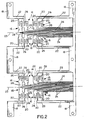
- FIGURE 2 is a plan view of a fragmented portion of a continuous metal strip from which the terminals of the connector are stamped, illustrating two sets of terminals for a pair of connectors;
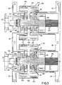
- FIGURE 3 is a view similar to that of Figure 2, illustrating a pair of one-piece housing structures overmolded about intermediate portions of the terminals;
- FIGURE 4 is a view of only one of the overmolded housing structures and a single set of terminals, as depicted in Figure 3;
- FIGURE 5 is a horizontal section taken generally along line 5-5 of Figure 4;
- FIGURE 6 is a sectional view similar to that of Figure 5, during a step of manufacture wherein the cantilever jack contact portions of the terminals have been bent into the housing cavity, and the base portion of the housing structure has been pivoted to a latched condition, versus the initial overmolded condition shown in Figure 5;
- FIGURE 7 is a front elevational view, looking toward the right-hand end of Figure 6, with the wire-driving portions of the housing structure in inoperative positions;
- FIGURE 8 is a vertical section taken generally along line 8-8 of Figure 6, again showing the wire-driving portions of the housing structure in inoperative positions, as depicted in Figure 7;
- FIGURE 9 is a view similar to that of Figure 8, with the wire-driving portions pivoted to their wire terminating positions;
- FIGURE 10 is a vertical section through the fully assembled and terminated modular connector, as taken generally along line 10-10 of Figure 1, in conjunction with a standard telephone plug; and
- FIGURE 11 is a view similar to that of Figure 10, showing the connector mounted within a particular housing environment.
- Referring to the drawings in greater detail, and first to Figure 1, the concepts of the invention are illustrated in a modular telephone connector or jack, generally designated 12, which includes a one-piece housing, generally designated 14. The housing is unitarily molded of dielectric material, such as plastic or the like, and will be described in greater detail hereinafter. Generally, a portion of the housing is overmolded about portions of a plurality of stamped metal terminals, generally designated 16, and the terminals are insulation-displacement-terminated to a plurality of telephone wires of a
telephone cable 19, all of which will be described in greater detail hereinafter. At this point, it should be understood that, although the concepts of the invention are disclosed herein embodied in a modular telephone connector or jack, various aspects of the invention are equally applicable for other types of electrical connectors. - The following detailed description is being presented in a step-by-step fashion involving initial manufacturing steps, initial sub-assembly steps prior to providing or shipping the pre-assembled connector to a user, and finally the telephone wire termination steps carried out by the user. This approach is believed to be most advantageous in presenting various aspects of the invention in a precise and understandable description.
- More particularly, referring first to Figure 2,
terminals 16 first are stamped from a continuous strip of sheet metal material to a blank configuration including a pair ofcontinuous carrier strips 18 which carry the terminals in stamped form through an appropriate stamping machine. Of course, the terminals are in a flat or planar configuration in the stamped blank of Figure 2. It can be seen that the terminals are joined byweb portions 20 andtransverse webs 22 tocarrier strips 18. It also can be seen that the terminals are stamped on opposite sides of atransverse center line 23, with four terminals on each side of the center line for a total "terminal cluster" of eight terminals for each telephone connector 12 (Fig. 1). - Each stamped
metal terminal 16 includes a resilient cantileverjack contact portion 24, a wireinsulation displacement portion 26 and anintermediate portion 28, although the right-hand terminals shown in Figure 2 have no distinct intermediate portion except integral areas of wireinsulation displacement portions 26. Eventually, cantilever jack contactportions 24 of the terminals will be severed from the right-hand carrier strip 18 and bent into theconnector housing 14, as will be described in greater detail hereinafter. - The next step in fabricating
modular telephone connector 12 is shown in Figures 3-5 and, generally, involves overmolding a one-piece housing subassembly structure about portions ofterminals 16, generally about the intermediate portions of at least some of the terminals. More particularly, an overmolded housing structure or subassembly, generally designated 30, includes a top or center overmoldedportion 32, amain housing portion 34, alatch portion 35 and a pair of wire-drivingportions 36. It can be seen that the top or center overmoldedportion 32 is molded about portions ofterminals 16 such that wireinsulation displacement portions 26 of the terminals are exposed exteriorly on opposite sides of the center overmolded portion of the housing subassembly structure. It also can be seen thatlatch portion 35 is overmolded about inner areas of cantileverjack contact portions 24, leaving considerable areas of the contact portions exposed for bending purposes, as described hereinafter. -
Main housing portion 34 includes an opening orcavity 38 which is provided for receiving a standard telephone plug, as will be more apparent hereinafter. The main housing portion is molded integral with top or center overmoldedportion 32 by aliving hinge 40. Each wire-drivingportion 36 also is molded integral with top or center overmoldedportion 32 by aliving hinge 42. Each wire-driving portion also includes slots orgrooves 44 in the top thereof for effecting insulation displacement termination of telephone wires to the wireinsulation displacement portions 26 ofterminals 16, again as will be described in greater detail hereinafter. - Lastly, at this point, in order to better understand the following detailed description, it should be noted in Figure 5 that
main housing portion 34 and wire-drivingportions 36 depend downwardly from top or center overmoldedportion 32 of the housing.Living hinges terminals 16, as described above, webs 20 (Fig. 2) then are severed from wireinsulation displacement portions 26 of the terminals, and cantileverjack contact portions 24 are severed from the right-hand carrier strip 18 of the stamped metal blank described above in relation to Figure 2. The cantilever jack contact portions now are rendered flexible or resilient because of their becoming free from the carrier strip. - After all of the extraneous webs and carrier strips have been removed from the stamped metal blank, cantilever
jack contact portions 24 then are formed or bent, and overmolded housing subassembly 30 is assembled into a subassembly for shipping to and/or use by an ultimate user. Of course, the entiremodular telephone connector 12 can be fully assembled in a manufacturing environment, if such an application is desirable. In either event, reference is made to Figures 6 and 7, particularly in conjunction with Figure 5. Cantileverjack contact portions 24 first are bent downwardly in the direction of arrow "A" (Fig. 5) to the configuration shown in Figure 6, whereby the contact portions now are disposed within cavity oropening 38.Main housing portion 34 then is pivoted about livinghinge 40 in the direction of arrow "B" (Fig. 5). As seen in Figure 7, the main housing portion will move upwardly between the side wire-drivingportions 36. When the main housing portion is moved to its fully assembled position as shown in Figure 6, the main housing portion is latched in that position by a pair of latch bosses 46 (Fig. 3) snapping into a pair of latch grooves 48 (Fig. 5) on the inside oflatch portion 35 of the overmolded housing structure. When in the assembled condition, cantilever jack contact portions are disposed within a comb structure 50 (Fig. 4) and seat on top of ledges 52 (Fig. 6) of the comb structure. When a standard telephone plug is inserted intoopening 38, the resilient cantilever jack contact portions engage contacts on the plug as the jack contact portions are biased upwardly in the direction of arrow "C" (Fig. 6). - Wire-driving
portions 36 ofovermolded housing structure 30 are used to drive insulated wires of telephone cable 18 (Fig. 1) into insulation displacement condition with wireinsulation displacement portions 26 ofterminals 16. Before proceeding, however, reference is made back to Figures 2-4 where it can be seen that each wireinsulation displacement portion 26 of each terminal 16 includes a pair of keyhole-shaped slots, each slot including anenlarged slot portion 54 communicating with anarrow slot portion 56. Theenlarged slot portions 54 are sized sufficiently larger than the insulated wires of the telephone cable so that the wires can be inserted easily into the enlarged slot portions. Thenarrow slot portions 56 are sufficiently narrow to cut through or pierce the insulation of the telephone wires to establish conductivity with the cores of the wires. - With the above understanding, and with reference to Figures 8 and 9, it can be seen in Figure 8 that wire-driving
portions 36 project outwardly of the center ortop portion 32 of theovermolded housing structure 30, with the wire-driving portions being interconnected to the center portion by living hinges 42. Therefore, the wire-driving portions can be pivoted upwardly in the direction of arrows "D" (Fig. 8). It also should be noted thatslots 44 in the wire-driving portions have widths which are at least slightly larger than the thickness of the metal material from whichinsulation displacement portions 26 ofterminals 16 are fabricated. Therefore, wire-drivingportions 36 can be pivoted upwardly in the direction of arrows "D", about living hinges 42, whereupon wireinsulation displacement portions 26 of the terminals enter intoslots 44 as shown in Figure 9. Since theenlarged slot portions 54 are disposed transversely outwardly relative tonarrow slot portions 56, as seen clearly in Figure 4, if insulated wires are located in the enlarged slot portions, wire-drivingportions 36 will drive the wires into thenarrow slot portions 56, as indicated by arrows "E" in Figure 9. Therefore, wire-drivingportions 36 of the overmolded housing structure are effective to terminate the telephone wires to the terminals.Slots 44 in the wire-driving portions should be of widths to establish an interference fit withinsulation displacement portions 26 of the terminals, so that the wire-driving portions remain in their terminating positions as shown in Figure 9. - Figure 10 shows
modular telephone connector 12 fully terminated to a plurality ofinsulated wires 60 oftelephone cable 19. This depiction corresponds to the "subassembly" illustration of Figures 6 and 7, except that theinsulated wires 60 are shown terminated toinsulation displacement portions 26 ofterminals 16, as described above in relation to Figures 8 and 9. It can be seen thattelephone cable 19 can be inserted through a recessedarea 62 ofmain housing portion 34, andinsulated wires 60 simply are fed upwardly through enlarged slot portions 54 (Fig. 4), whereupon wire-drivingportions 36 of the overmolded housing structure can be used to drive the insulated wires into thenarrow slot portions 56, as described above. The modular telephone connector now is fully assembled and ready to receive astandard telephone plug 64 insertable into opening 38 in the direction of arrow "F", as shown in Figure 10. - Lastly, Figure 11 illustrates an application of using
modular telephone connector 12 within aparticular housing 66 which includes afront aperture 68 through which telephone plug 64 can be inserted into opening 38 in the modular telephone connector. Appropriate contacts on the plug (not shown) will engage resilient cantileverjack contact portions 24 and bias the contact portions upwardly in the direction of arrow "C". - It will be understood that the invention may be embodied in other specific forms without departing from the spirit or central characteristics thereof. The present examples and embodiments, therefore, are to be considered in all respects as illustrative and not restrictive, and the invention is not to be limited to the details given herein.
Claims (19)
- In a modular telephone connector (12) which includes a housing (14) defining a standard telephone jack, and a plurality of stamped metal terminals (16) each having a resilient cantilever jack contact portion (24) and a wire insulation displacement portion (26), wherein the improvement comprises said housing being a one-piece structure overmolded about portions of the stamped metal terminals with the wire insulation displacement portions thereof exposed for receiving insulated telephone wires (60), the housing including a cavity (38) for receiving a standard telephone plug (64), and the cantilever jack contact portions (24) of the terminals being exposed by the overmolded housing adjacent the cavity whereby the contact portions can be bent into the cavity.
- In a modular telephone connector as set forth in claim 1, wherein said wire insulation displacement portions (26) of the terminals (16) include closed keyhole-shaped insulation displacement slots defining enlarged slot portions (54) sized for receiving the insulated telephone wires (60), and narrow slot portions communicating with the enlarged slot portions (56) for piercing the insulation of the telephone wires when the wires are moved from the enlarged slot portions with the narrow slot portions.
- In a modular telephone connector as set forth in claim 2, wherein said housing (14) includes at least one wire-driving portion (36) molded integrally therewith and movable into engagement with at least some of the insulated telephone wires to drive the wires into the narrow slot portions (56) of at least some of the insulation displacement slots.
- In a modular telephone connector as set forth in claim 3, including a living hinge portion (42) integrally connecting the wire-driving portion to afford driving movement thereof.
- In a modular telephone connector as set forth in claim 4, wherein the wire insulation displacement portions (26) of some of the terminals (16) project from opposite sides of the housing, and including a pair of said wire-driving portions (36) integrally connected on opposite sides of the housing.
- In a modular telephone connector as set forth in claim 1, wherein said housing (14) includes at least one wire-driving portion (36) molded integrally therewith and movable into engagement with at least some of the insulated telephone wires (60) to drive the wires into insulation-piercing condition with at least some of the insulation displacement portions (26) of the terminals (16).
- In a modular telephone connector as set forth in claim 6, including a living hinge portion (42) integrally connecting the wire-driving portion to afford driving movement thereof.
- In a modular telephone connector as set forth in claim 7, wherein the wire insulation displacement portions (26) of some of the terminals (16) project from opposite sides of the housing, and including a pair of said wire-driving portions (36) integrally connected on opposite sides of the housing.
- In a modular telephone connector as set forth in claim 1, wherein said one-piece housing structure includes a center portion (32) overmolded about portions of the stamped metal terminals, a main housing portion (34) at one end of the center portion defining said cavity and molded integrally with the center portion and movable into an assembled condition, a latch portion (35) at an opposite end of the center portion for latching engagement with the main housing portion, and at least one wire-driving portion (36) molded integrally with the center portion and movable into engagement with at least some of the insulated telephone wires to drive the wires into the insulation displacement portions (26) of the terminals (16).
- In a modular telephone connector as set forth in claim 9, including a living hinge portion (42) integrally molded between the center portion (32) and the wire-driving portion (36) to afford driving movement thereof.
- In a modular telephone connector as set forth in claim 10, wherein the wire insulation displacement portions (26) of the terminals (16) project from opposite sides of the center portion (32) of the housing, and including a pair of said wire-driving portions (36) molded integrally with the center portion on opposite sides thereof.
- In a modular telephone connector as set forth in claim 9, including a living hinge portion (42) integrally molded between the main housing portion (34) and the center portion (32) of the housing to afford movement therebetween.
- A method of fabricating and assembling a modular telephone connector (12), comprising the steps of:
stamping a plurality of terminals (16) from sheet metal material, each terminal having a resilient cantilever jack contact portion (24) and a wire insulation displacement portion (26);
overmolding a one-piece housing structure (14) about areas of the terminals, the housing structure being molded with a center portion (32) overmolded about said areas of the terminals, exposing said cantilever jack contact portions (24) and said wire insulation displacement portions (26), a main housing portion (34) molded by a living hinge (40) integral with the center portion and defining a cavity (38) for receiving a standard telephone plug (64), and at least one wire-driving portion (36) molded integrally with the center portion by a living hinge (42);
moving said main housing portion (34) about its living hinge (40) into juxtaposition with the center portion (32) of the housing;
inserting a plurality of insulated telephone wires (60) into the insulation displacement portions (26) of the terminals (16); and
moving the wire-driving portion (36) of the housing about its living hinge (42) into engagement with the insulated telephone wires to drive the wires into the insulation displacement portions of the terminals. - The method of claim 13, including the step of stamping the insulation displacement portions (26) of the terminals (16) with closed keyhole-shaped insulation displacement slots having enlarged slot portions (54) sized for receiving the insulated telephone wires and narrow slot portions (56) communicating with the enlarged slot portions for piercing the insulation of the telephone wires, whereby said wire-driving portion (36) of the housing is effective to move the insulated telephone wires from the enlarged slot portions into the narrow slot portions of the closed keyhole-shaped slots.
- In a modular electrical connector (12) which includes a housing (14), and a plurality of terminals (16) mounted in the housing and having exposed wire insulation displacement portions (26), wherein the improvement comprises said housing being a one-piece molded structure including an integral wire-driving portion (36) movable into engagement with a plurality of insulated wires (60) to drive the wires into the insulation displacement portions of the terminals.
- In a modular electrical connector as set forth in claim 15, including a living hinge portion (42) integrally connecting the wire-driving portion to afford driving movement thereof.
- In a modular electrical connector as set forth in claim 16, wherein the wire insulation displacement portions (26) of some of the terminals (16) project from opposite sides of the housing, and including a pair of said wire-driving portions (36) integrally connected on opposite sides of the housing.
- In a modular electrical connector as set forth in claim 15, wherein said wire insulation displacement portions (26) of the terminals (16) include closed keyhole-shaped insulation displacement slots defining enlarged slot portions (54) sized for receiving the insulated wires (60), and narrow slot portions (56) communicating with the enlarged slot portions for piercing the insulation of the wires when the wires are moved from the enlarged slot portions with the narrow slot portions.
- In a modular telephone connector (12) which includes a housing (14) defining a standard telephone jack, and a plurality of stamped metal terminals (16) each having a resilient cantilever jack contact portion (24) and a wire insulation displacement portion (26), wherein the improvement comprises said wire insulation displacement portions (26) of the terminals including closed keyhole-shaped insulation displacement slots defining enlarged slot portions (54) sized for receiving the insulated telephone wires and narrow slot portions communicating with the enlarged slot portions (56) for piercing the insulation of the telephone wires when the wires are moved from the enlarged slot portions into the narrow slot portions.
Priority Applications (11)
| Application Number | Priority Date | Filing Date | Title |
|---|---|---|---|
| EP92110606A EP0583486B1 (en) | 1992-06-24 | 1992-06-24 | Modular electrical connector |
| DE69210396T DE69210396T2 (en) | 1992-06-24 | 1992-06-24 | Modular electrical connector |
| SG1996005579A SG44685A1 (en) | 1992-06-24 | 1992-06-24 | Modular electrical connector |
| US08/056,106 US5304074A (en) | 1992-06-24 | 1993-05-03 | Modular electrical connector |
| TW082103574A TW221530B (en) | 1992-06-24 | 1993-05-07 | |
| CA002095898A CA2095898C (en) | 1992-06-24 | 1993-05-10 | Modular electrical connector |
| MYPI93001039A MY110900A (en) | 1992-06-24 | 1993-05-29 | Modular electrical connector |
| AU40042/93A AU664619B2 (en) | 1992-06-24 | 1993-06-04 | Modular electrical connector |
| JP5169597A JP2552241B2 (en) | 1992-06-24 | 1993-06-17 | Modular telephone connector and manufacturing method thereof |
| MX9303728A MX9303728A (en) | 1992-06-24 | 1993-06-21 | MODULAR ELECTRICAL CONNECTOR. |
| KR1019930011299A KR970003370B1 (en) | 1992-06-24 | 1993-06-21 | Modular electrical connector |
Applications Claiming Priority (2)
| Application Number | Priority Date | Filing Date | Title |
|---|---|---|---|
| EP92110606A EP0583486B1 (en) | 1992-06-24 | 1992-06-24 | Modular electrical connector |
| SG1996005579A SG44685A1 (en) | 1992-06-24 | 1992-06-24 | Modular electrical connector |
Publications (2)
| Publication Number | Publication Date |
|---|---|
| EP0583486A1 true EP0583486A1 (en) | 1994-02-23 |
| EP0583486B1 EP0583486B1 (en) | 1996-05-01 |
Family
ID=26130968
Family Applications (1)
| Application Number | Title | Priority Date | Filing Date |
|---|---|---|---|
| EP92110606A Expired - Lifetime EP0583486B1 (en) | 1992-06-24 | 1992-06-24 | Modular electrical connector |
Country Status (9)
| Country | Link |
|---|---|
| US (1) | US5304074A (en) |
| EP (1) | EP0583486B1 (en) |
| JP (1) | JP2552241B2 (en) |
| KR (1) | KR970003370B1 (en) |
| AU (1) | AU664619B2 (en) |
| CA (1) | CA2095898C (en) |
| DE (1) | DE69210396T2 (en) |
| MX (1) | MX9303728A (en) |
| SG (1) | SG44685A1 (en) |
Cited By (5)
| Publication number | Priority date | Publication date | Assignee | Title |
|---|---|---|---|---|
| EP0700129A1 (en) | 1994-09-05 | 1996-03-06 | Yves Saligny | Modular electric connector and terminal block comprising such connectors |
| WO1996039731A1 (en) * | 1995-06-06 | 1996-12-12 | Baxter International Inc. | Connector for electrical cable and method of making |
| WO1996042125A1 (en) * | 1995-06-09 | 1996-12-27 | Astralux Dynamics Limited | Connector apparatus |
| FR2760136A1 (en) * | 1997-02-27 | 1998-08-28 | Pouyet Sa | MODULAR JACK TYPE WALL SOCKET |
| WO2000074174A1 (en) * | 1999-06-01 | 2000-12-07 | Krone Gmbh | Unit with wire termination and rj style plug |
Families Citing this family (11)
| Publication number | Priority date | Publication date | Assignee | Title |
|---|---|---|---|---|
| US5328390A (en) * | 1992-09-01 | 1994-07-12 | Hubbell Incorporated | Modular telecommunication jack adapter |
| US5419720A (en) * | 1994-03-16 | 1995-05-30 | Chen; Michael | Structure of jack for modular plugs |
| US5807133A (en) * | 1997-04-15 | 1998-09-15 | Lucent Technologies Inc. | Insulation displacement connector |
| US6003226A (en) * | 1997-05-14 | 1999-12-21 | Molex Incorporated | Method for manufacturing electrical connectors |
| US6394835B1 (en) * | 1999-02-16 | 2002-05-28 | Hubbell Incorporated | Wiring unit with paired in-line insulation displacement contacts |
| JP4575606B2 (en) * | 2001-02-13 | 2010-11-04 | 神保電器株式会社 | Information outlet and cover member used for the outlet |
| US6877218B2 (en) * | 2001-06-21 | 2005-04-12 | Rauland-Borg Corporation | Hand tool for applying electrical connectors |
| CN2638266Y (en) * | 2003-06-05 | 2004-09-01 | 富士康(昆山)电脑接插件有限公司 | Module connector |
| US7160140B1 (en) * | 2005-07-13 | 2007-01-09 | Gelcore Llc | LED string light engine |
| US7381083B2 (en) | 2006-09-13 | 2008-06-03 | John Mezzalingua Associates, Inc. | Ethernet connector apparatus and method |
| US8480422B2 (en) * | 2010-06-17 | 2013-07-09 | Apple Inc. | Connector assemblies with overmolds |
Citations (4)
| Publication number | Priority date | Publication date | Assignee | Title |
|---|---|---|---|---|
| US4269467A (en) * | 1979-10-23 | 1981-05-26 | Amp Incorporated | Electrical connector receptacle having molded conductors |
| DE3522112A1 (en) * | 1985-06-20 | 1987-01-02 | Siemens Ag | Contact device |
| WO1990004863A1 (en) * | 1988-10-17 | 1990-05-03 | Poul Kjeldahl | An electric connector terminal, primarily a so-called isdn-plug, and a method of manufacturing contact strips therefor |
| US5030133A (en) * | 1990-07-25 | 1991-07-09 | Itt Corporation | Connector with attached caps |
Family Cites Families (12)
| Publication number | Priority date | Publication date | Assignee | Title |
|---|---|---|---|---|
| US4327958A (en) * | 1980-05-05 | 1982-05-04 | Amp Incorporated | Connector jack |
| US4341430A (en) * | 1980-11-05 | 1982-07-27 | Amp Incorporated | Flat cable connector |
| US4413872A (en) * | 1981-05-11 | 1983-11-08 | Amp Incorporated | Preloaded electrical connector |
| US4995830A (en) * | 1984-10-02 | 1991-02-26 | Ira Eckhaus | Electrical wire connectors |
| US4820564A (en) * | 1984-10-29 | 1989-04-11 | The Boeing Company | Blind-side repair patch kit |
| FR2630481B1 (en) * | 1988-04-20 | 1992-04-24 | Freyssinet Int Stup | IMPROVEMENTS ON CABLE ANCHORING DEVICES |
| US4865564A (en) * | 1988-06-10 | 1989-09-12 | American Telephone And Telegraph Company | Wall mounted connecting block |
| US4820192A (en) * | 1988-06-10 | 1989-04-11 | American Telephone And Telegraph Company | Connecting block construction |
| JPH0244267U (en) * | 1988-09-20 | 1990-03-27 | ||
| JPH02162667A (en) * | 1988-12-15 | 1990-06-22 | Oki Densen Kk | Molded board type modular jack |
| US4975078A (en) * | 1989-12-15 | 1990-12-04 | Panduit Corp. | Modular telephone connector |
| JPH0770332B2 (en) * | 1990-06-26 | 1995-07-31 | 松下電工株式会社 | Exposed Modular Jack |
-
1992
- 1992-06-24 DE DE69210396T patent/DE69210396T2/en not_active Expired - Fee Related
- 1992-06-24 EP EP92110606A patent/EP0583486B1/en not_active Expired - Lifetime
- 1992-06-24 SG SG1996005579A patent/SG44685A1/en unknown
-
1993
- 1993-05-03 US US08/056,106 patent/US5304074A/en not_active Expired - Fee Related
- 1993-05-10 CA CA002095898A patent/CA2095898C/en not_active Expired - Fee Related
- 1993-06-04 AU AU40042/93A patent/AU664619B2/en not_active Ceased
- 1993-06-17 JP JP5169597A patent/JP2552241B2/en not_active Expired - Lifetime
- 1993-06-21 KR KR1019930011299A patent/KR970003370B1/en not_active IP Right Cessation
- 1993-06-21 MX MX9303728A patent/MX9303728A/en not_active IP Right Cessation
Patent Citations (4)
| Publication number | Priority date | Publication date | Assignee | Title |
|---|---|---|---|---|
| US4269467A (en) * | 1979-10-23 | 1981-05-26 | Amp Incorporated | Electrical connector receptacle having molded conductors |
| DE3522112A1 (en) * | 1985-06-20 | 1987-01-02 | Siemens Ag | Contact device |
| WO1990004863A1 (en) * | 1988-10-17 | 1990-05-03 | Poul Kjeldahl | An electric connector terminal, primarily a so-called isdn-plug, and a method of manufacturing contact strips therefor |
| US5030133A (en) * | 1990-07-25 | 1991-07-09 | Itt Corporation | Connector with attached caps |
Cited By (8)
| Publication number | Priority date | Publication date | Assignee | Title |
|---|---|---|---|---|
| US5803770A (en) * | 1994-02-23 | 1998-09-08 | Baxter International Inc. | Connector for electrical cable and method of making |
| EP0700129A1 (en) | 1994-09-05 | 1996-03-06 | Yves Saligny | Modular electric connector and terminal block comprising such connectors |
| WO1996039731A1 (en) * | 1995-06-06 | 1996-12-12 | Baxter International Inc. | Connector for electrical cable and method of making |
| WO1996042125A1 (en) * | 1995-06-09 | 1996-12-27 | Astralux Dynamics Limited | Connector apparatus |
| AU707206B2 (en) * | 1995-06-09 | 1999-07-08 | Astralux Dynamics Limited | Connector apparatus |
| FR2760136A1 (en) * | 1997-02-27 | 1998-08-28 | Pouyet Sa | MODULAR JACK TYPE WALL SOCKET |
| EP0863583A1 (en) * | 1997-02-27 | 1998-09-09 | Pouyet S.A. | Modular jack type wall female socket |
| WO2000074174A1 (en) * | 1999-06-01 | 2000-12-07 | Krone Gmbh | Unit with wire termination and rj style plug |
Also Published As
| Publication number | Publication date |
|---|---|
| CA2095898A1 (en) | 1993-12-25 |
| JPH06203906A (en) | 1994-07-22 |
| DE69210396T2 (en) | 1996-11-28 |
| EP0583486B1 (en) | 1996-05-01 |
| DE69210396D1 (en) | 1996-06-05 |
| US5304074A (en) | 1994-04-19 |
| KR970003370B1 (en) | 1997-03-17 |
| JP2552241B2 (en) | 1996-11-06 |
| AU664619B2 (en) | 1995-11-23 |
| MX9303728A (en) | 1994-02-28 |
| SG44685A1 (en) | 1997-12-19 |
| AU4004293A (en) | 1994-01-06 |
| CA2095898C (en) | 1997-07-08 |
| KR940001495A (en) | 1994-01-11 |
Similar Documents
| Publication | Publication Date | Title |
|---|---|---|
| US5304074A (en) | Modular electrical connector | |
| US4193654A (en) | Electrical connector receptacles | |
| JP2993644B2 (en) | Flat cable connector | |
| US4718866A (en) | Electrical connector shield case and method of making same | |
| EP0501629B1 (en) | Cable strain relief back shell | |
| US4292736A (en) | Method for making jack type receptacles | |
| US5171161A (en) | Electrical connector assemblies | |
| US5236375A (en) | Electrical connector assemblies | |
| JPS6226557B2 (en) | ||
| EP0204409B1 (en) | Two piece modular receptacle and method of making same | |
| US5133672A (en) | Insulation displacement terminal | |
| US5547391A (en) | Commoning electrical connector | |
| EP0795930A1 (en) | High contact force pin-receiving electrical contact | |
| AU719953B2 (en) | Method of forming electrical connector | |
| GB1561989A (en) | Insulation-piercing electrical connector unit embodying the same | |
| EP0512438A2 (en) | Electrical connector assemblies | |
| US5035658A (en) | Electrical connector and terminal therefor | |
| JP3044378U (en) | Flat insulation-cut terminal for electrical connectors | |
| EP0009867B1 (en) | An electrical plug receptacle connector and a method of manufacturing such a connector | |
| US5244420A (en) | Electrical connector assembly | |
| US4602838A (en) | Electronic key assemblies | |
| EP0249330A2 (en) | Insulation displacement terminal and connector | |
| US5252094A (en) | Electrical connector with improved terminal retention | |
| EP0055876A2 (en) | Improved discrete wire insulation displacement connector | |
| EP1058342B1 (en) | A terminal fitting and a production method |
Legal Events
| Date | Code | Title | Description |
|---|---|---|---|
| PUAI | Public reference made under article 153(3) epc to a published international application that has entered the european phase |
Free format text: ORIGINAL CODE: 0009012 |
|
| AK | Designated contracting states |
Kind code of ref document: A1 Designated state(s): DE FR GB IT NL SE |
|
| 17P | Request for examination filed |
Effective date: 19940730 |
|
| 17Q | First examination report despatched |
Effective date: 19950322 |
|
| GRAH | Despatch of communication of intention to grant a patent |
Free format text: ORIGINAL CODE: EPIDOS IGRA |
|
| ITF | It: translation for a ep patent filed |
Owner name: DE DOMINICIS & MAYER S.R.L. |
|
| GRAA | (expected) grant |
Free format text: ORIGINAL CODE: 0009210 |
|
| AK | Designated contracting states |
Kind code of ref document: B1 Designated state(s): DE FR GB IT NL SE |
|
| REF | Corresponds to: |
Ref document number: 69210396 Country of ref document: DE Date of ref document: 19960605 |
|
| ET | Fr: translation filed | ||
| PLBE | No opposition filed within time limit |
Free format text: ORIGINAL CODE: 0009261 |
|
| STAA | Information on the status of an ep patent application or granted ep patent |
Free format text: STATUS: NO OPPOSITION FILED WITHIN TIME LIMIT |
|
| 26N | No opposition filed | ||
| PGFP | Annual fee paid to national office [announced via postgrant information from national office to epo] |
Ref country code: NL Payment date: 20000320 Year of fee payment: 9 |
|
| PGFP | Annual fee paid to national office [announced via postgrant information from national office to epo] |
Ref country code: SE Payment date: 20000602 Year of fee payment: 9 |
|
| PGFP | Annual fee paid to national office [announced via postgrant information from national office to epo] |
Ref country code: GB Payment date: 20010502 Year of fee payment: 10 |
|
| PGFP | Annual fee paid to national office [announced via postgrant information from national office to epo] |
Ref country code: FR Payment date: 20010531 Year of fee payment: 10 |
|
| PG25 | Lapsed in a contracting state [announced via postgrant information from national office to epo] |
Ref country code: SE Free format text: LAPSE BECAUSE OF NON-PAYMENT OF DUE FEES Effective date: 20010625 |
|
| PGFP | Annual fee paid to national office [announced via postgrant information from national office to epo] |
Ref country code: DE Payment date: 20010627 Year of fee payment: 10 |
|
| PG25 | Lapsed in a contracting state [announced via postgrant information from national office to epo] |
Ref country code: NL Free format text: LAPSE BECAUSE OF NON-PAYMENT OF DUE FEES Effective date: 20020101 |
|
| REG | Reference to a national code |
Ref country code: GB Ref legal event code: IF02 |
|
| EUG | Se: european patent has lapsed |
Ref document number: 92110606.8 |
|
| NLV4 | Nl: lapsed or anulled due to non-payment of the annual fee |
Effective date: 20020101 |
|
| PG25 | Lapsed in a contracting state [announced via postgrant information from national office to epo] |
Ref country code: GB Free format text: LAPSE BECAUSE OF NON-PAYMENT OF DUE FEES Effective date: 20020624 |
|
| PG25 | Lapsed in a contracting state [announced via postgrant information from national office to epo] |
Ref country code: DE Free format text: LAPSE BECAUSE OF NON-PAYMENT OF DUE FEES Effective date: 20030101 |
|
| GBPC | Gb: european patent ceased through non-payment of renewal fee |
Effective date: 20020624 |
|
| PG25 | Lapsed in a contracting state [announced via postgrant information from national office to epo] |
Ref country code: FR Free format text: LAPSE BECAUSE OF NON-PAYMENT OF DUE FEES Effective date: 20030228 |
|
| REG | Reference to a national code |
Ref country code: FR Ref legal event code: ST |
|
| PG25 | Lapsed in a contracting state [announced via postgrant information from national office to epo] |
Ref country code: IT Free format text: LAPSE BECAUSE OF NON-PAYMENT OF DUE FEES;WARNING: LAPSES OF ITALIAN PATENTS WITH EFFECTIVE DATE BEFORE 2007 MAY HAVE OCCURRED AT ANY TIME BEFORE 2007. THE CORRECT EFFECTIVE DATE MAY BE DIFFERENT FROM THE ONE RECORDED. Effective date: 20050624 |