EP0583093A1 - Optische Faserpackung für hohen Geschwindigkeitsabzug - Google Patents
Optische Faserpackung für hohen Geschwindigkeitsabzug Download PDFInfo
- Publication number
- EP0583093A1 EP0583093A1 EP93305773A EP93305773A EP0583093A1 EP 0583093 A1 EP0583093 A1 EP 0583093A1 EP 93305773 A EP93305773 A EP 93305773A EP 93305773 A EP93305773 A EP 93305773A EP 0583093 A1 EP0583093 A1 EP 0583093A1
- Authority
- EP
- European Patent Office
- Prior art keywords
- optical fiber
- convolutions
- package
- coating material
- constituent
- Prior art date
- Legal status (The legal status is an assumption and is not a legal conclusion. Google has not performed a legal analysis and makes no representation as to the accuracy of the status listed.)
- Granted
Links
- 239000013307 optical fiber Substances 0.000 title claims abstract description 100
- 239000000463 material Substances 0.000 claims abstract description 82
- 239000011248 coating agent Substances 0.000 claims abstract description 46
- 238000000576 coating method Methods 0.000 claims abstract description 46
- 239000000470 constituent Substances 0.000 claims abstract description 13
- 229920002037 poly(vinyl butyral) polymer Polymers 0.000 claims description 8
- 230000001464 adherent effect Effects 0.000 claims 1
- 239000000853 adhesive Substances 0.000 abstract description 38
- 230000001070 adhesive effect Effects 0.000 abstract description 38
- 238000010438 heat treatment Methods 0.000 abstract description 6
- 238000005253 cladding Methods 0.000 abstract description 3
- 230000032798 delamination Effects 0.000 abstract description 3
- 238000004804 winding Methods 0.000 abstract description 3
- 239000000835 fiber Substances 0.000 description 23
- 239000010410 layer Substances 0.000 description 18
- 238000000034 method Methods 0.000 description 10
- 238000004891 communication Methods 0.000 description 9
- 230000003287 optical effect Effects 0.000 description 8
- 239000012815 thermoplastic material Substances 0.000 description 7
- 230000009477 glass transition Effects 0.000 description 4
- 238000013508 migration Methods 0.000 description 4
- 230000005012 migration Effects 0.000 description 4
- 239000002904 solvent Substances 0.000 description 4
- 230000007704 transition Effects 0.000 description 4
- ZWEHNKRNPOVVGH-UHFFFAOYSA-N 2-Butanone Chemical group CCC(C)=O ZWEHNKRNPOVVGH-UHFFFAOYSA-N 0.000 description 3
- 239000004020 conductor Substances 0.000 description 3
- 230000002411 adverse Effects 0.000 description 2
- 238000001816 cooling Methods 0.000 description 2
- 239000000203 mixture Substances 0.000 description 2
- 229920003023 plastic Polymers 0.000 description 2
- 239000004033 plastic Substances 0.000 description 2
- 238000012545 processing Methods 0.000 description 2
- 230000005855 radiation Effects 0.000 description 2
- 238000003848 UV Light-Curing Methods 0.000 description 1
- 238000013459 approach Methods 0.000 description 1
- 238000005452 bending Methods 0.000 description 1
- 230000009286 beneficial effect Effects 0.000 description 1
- 230000005540 biological transmission Effects 0.000 description 1
- 230000015572 biosynthetic process Effects 0.000 description 1
- 238000012512 characterization method Methods 0.000 description 1
- 239000002131 composite material Substances 0.000 description 1
- 238000001723 curing Methods 0.000 description 1
- 230000007423 decrease Effects 0.000 description 1
- 230000000593 degrading effect Effects 0.000 description 1
- 239000002270 dispersing agent Substances 0.000 description 1
- 229920006240 drawn fiber Polymers 0.000 description 1
- 239000002355 dual-layer Substances 0.000 description 1
- 230000007613 environmental effect Effects 0.000 description 1
- 239000011521 glass Substances 0.000 description 1
- 239000007788 liquid Substances 0.000 description 1
- 239000011344 liquid material Substances 0.000 description 1
- 230000007774 longterm Effects 0.000 description 1
- 230000014759 maintenance of location Effects 0.000 description 1
- 238000004519 manufacturing process Methods 0.000 description 1
- 239000007769 metal material Substances 0.000 description 1
- 239000012768 molten material Substances 0.000 description 1
- 238000004806 packaging method and process Methods 0.000 description 1
- 230000035515 penetration Effects 0.000 description 1
- 239000000843 powder Substances 0.000 description 1
- 239000011253 protective coating Substances 0.000 description 1
- 238000009877 rendering Methods 0.000 description 1
- 230000002441 reversible effect Effects 0.000 description 1
- 238000000926 separation method Methods 0.000 description 1
- 230000035939 shock Effects 0.000 description 1
- 238000003860 storage Methods 0.000 description 1
- 238000012360 testing method Methods 0.000 description 1
- 238000012546 transfer Methods 0.000 description 1
Images

Classifications
-
- G—PHYSICS
- G02—OPTICS
- G02B—OPTICAL ELEMENTS, SYSTEMS OR APPARATUS
- G02B6/00—Light guides; Structural details of arrangements comprising light guides and other optical elements, e.g. couplings
- G02B6/44—Mechanical structures for providing tensile strength and external protection for fibres, e.g. optical transmission cables
- G02B6/4439—Auxiliary devices
- G02B6/4457—Bobbins; Reels
-
- F—MECHANICAL ENGINEERING; LIGHTING; HEATING; WEAPONS; BLASTING
- F41—WEAPONS
- F41G—WEAPON SIGHTS; AIMING
- F41G7/00—Direction control systems for self-propelled missiles
- F41G7/20—Direction control systems for self-propelled missiles based on continuous observation of target position
- F41G7/30—Command link guidance systems
- F41G7/32—Command link guidance systems for wire-guided missiles
-
- G—PHYSICS
- G02—OPTICS
- G02B—OPTICAL ELEMENTS, SYSTEMS OR APPARATUS
- G02B6/00—Light guides; Structural details of arrangements comprising light guides and other optical elements, e.g. couplings
- G02B6/44—Mechanical structures for providing tensile strength and external protection for fibres, e.g. optical transmission cables
- G02B6/4401—Optical cables
- G02B6/4429—Means specially adapted for strengthening or protecting the cables
- G02B6/443—Protective covering
-
- G—PHYSICS
- G02—OPTICS
- G02B—OPTICAL ELEMENTS, SYSTEMS OR APPARATUS
- G02B6/00—Light guides; Structural details of arrangements comprising light guides and other optical elements, e.g. couplings
- G02B6/44—Mechanical structures for providing tensile strength and external protection for fibres, e.g. optical transmission cables
- G02B6/4401—Optical cables
- G02B6/4429—Means specially adapted for strengthening or protecting the cables
- G02B6/443—Protective covering
- G02B6/4431—Protective covering with provision in the protective covering, e.g. weak line, for gaining access to one or more fibres, e.g. for branching or tapping
-
- G—PHYSICS
- G02—OPTICS
- G02B—OPTICAL ELEMENTS, SYSTEMS OR APPARATUS
- G02B6/00—Light guides; Structural details of arrangements comprising light guides and other optical elements, e.g. couplings
- G02B6/44—Mechanical structures for providing tensile strength and external protection for fibres, e.g. optical transmission cables
- G02B6/4479—Manufacturing methods of optical cables
- G02B6/4484—Manufacturing methods of optical cables with desired surplus length between fibres and protection features
-
- G—PHYSICS
- G02—OPTICS
- G02B—OPTICAL ELEMENTS, SYSTEMS OR APPARATUS
- G02B6/00—Light guides; Structural details of arrangements comprising light guides and other optical elements, e.g. couplings
- G02B6/44—Mechanical structures for providing tensile strength and external protection for fibres, e.g. optical transmission cables
- G02B6/4479—Manufacturing methods of optical cables
- G02B6/4486—Protective covering
Definitions
- This invention relates to a package of optical fiber suitable for high speed payout.
- a continuous length of optical fiber is drawn from an optical preform which may be made by any one of several known processes. Afterwards, or as part of a tandem process, the drawn fiber is coated, cured, measured and taken up, desirably in an automatic takeup apparatus, on a spool.
- the spool on which the optical fiber is taken up has other uses. It is used to store the optical fiber, to pay out and to take up the fiber for other operations such as ribboning, cabling, and rewinding and is used to ship optical fiber which is wound thereon to other companies which further process the fiber. Also, it may be used in weapons and communications systems in which it may be attached to a control station.
- optical fiber is less robust than metallic conductors, rendering it subject to breakage. Aside from breakage, optical fiber communication performance may be degraded by microbends in the fiber which are generated by bending or by other stresses to which the fiber is subjected. Such damage to an optical fiber not only reduces the long-term durability of the fiber, but also causes losses in the strength and in the content of the optical signal.
- a typical optical fiber application in a weapons systems involves the packaging of a continuous length of optical fiber on a carrier bobbin which is positioned inside a vehicle.
- a vehicle commonly is referred to as a tethered vehicle.
- One end of the fiber is attached to operational devices in the vehicle, whereas the other end of the fiber is connected to a control or communications station at a launch site. During and after launch, two-way communication with the vehicle is conducted.
- a problem in the optical fiber guidance of tethered vehicles relates to the successful unwinding of the fiber from a carrier bobbin as the bobbin is propelled along with the vehicle.
- the leading end of the optical fiber is connected to a guidance system for controlling the path of travel of the vehicle. It becomes important for the optical fiber to be payed off from the bobbin without the occurrence of snags, otherwise the fiber may break and the control system rendered inoperable.
- Contributing to the successful payout of the optical fiber is a precision wound package. Further, not only must the convolutions be wound with precision, they also must remain in place as wound during handling and when deployed. In other words, the optical fiber package must be a highly stable one. On the other hand, payout must occur easily without the necessity of high pulling forces to remove each convolution of fiber from the carrier bobbin.
- optical fiber packages for use in tethered vehicles, many layers of optical fiber are wound on a base layer of wire.
- An adhesive material between the optical fiber turns functions to hold the package together, forming a stable structure which is resistant to environmental extremes, shock and vibration.
- the adhesive material which is used to hold together the convolutions must have a minimal impact on the optical performance of the wound optical fiber, and yet it must allow the optical fiber to be payed out with a controlled force at the peel-off point as the outermost turn is unwound at high speed.
- the adhesive system must provide tackiness which is sufficiently low to permit a helical pattern of payout at speeds which may be relatively low to speeds which may be in the supersonic range. Excessive tackiness threatens fiber integrity by forming an extreme bend at the peel-off point. On the other hand, not enough tack may result in failure through dynamic instability on the bobbin surface.
- optical attenuation at the peel off-point of each successive convolution may occur through localized macrobending, degrading the integrity of data and video transmission. Typical peel-off point attenuation of each successive convolution may contribute 3 or more dB to the overall loss.
- Current techniques for providing a sought-after stable package include providing a length of optical fiber to be wound with an adhesive material which is not tacky at room temperature but which becomes tacky at a predetermined temperature. After the optical fiber has been precision mound wound on a bobbin, the bobbin is subjected to the predetermined temperature to cause the adhesive material to become tacky and cause each convolution to adhere to at least a portion of adjacent convolutions. The adhesion is sufficient to cause a precision wound package to be maintained, but is such as to allow separation of convolutions during payout without the occurrence of breaks. See U.S. patent 4,959,049.
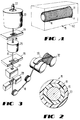
- the optical fiber 16 typically includes a light transmitting portion 18 such as a core and a cladding and at least one layer of a coating material (see FIG. 2).
- the optical fiber 16 is shown as including two layers of radiation cured coating materials.
- An inner layer 19 of a primary coating material protects the fiber from microbending and an outer layer 20 of a secondary coating material protects the fiber from mechanical damage.
- the coating materials of the two layers for fiber herein are the same.
- FIG. 3 there is shown an apparatus which is used to draw the light transmitting portion 18 from a specially prepared cylindrical preform 22 and then to coat the optical fiber.
- the optical fiber light transmitting portion is formed by locally and symmetrically heating the preform 22 to a temperature of about 2000°C. As the preform 22 is fed into and through a furnace 23, the light transmitting portion 18 is drawn from the molten material.
- the draw system includes the furnace 23, wherein the preform 22 is drawn down to the optical fiber size, after which the light transmitting portion 18 is pulled from the heat zone.
- the diameter of the portion 18 which is measured by a device 24 at a point below the furnace 23 becomes an input into a control system.
- the measured diameter is compared to the desired value and an output signal is generated to adjust the draw speed such that the fiber diameter approaches the desired value.
- a protective coating system is applied by an apparatus 25 to provide the coated optical fiber 16.
- One method of applying dual layers 19 and 20 of coating materials to a moving optical fiber is disclosed in U.S. patent 4,474,830 which issued on October 2, 1984, in the name of C. R. Taylor.
- an ultraviolet light (UV) device 27 for treating the coating material to cure the coating material and a device 28 for measuring the outer diameter of the coated fiber it is moved through a capstan 29 and is taken up on a spool 32 for testing and further processing.
- UV ultraviolet light
- a coating system which is applied to the optical fiber after it has been drawn from the preform preferably comprises the two layers 19 and 20 of a radiation cured polymeric material.
- the coating materials are applied herein in two layers, it should be understood that the coating material could be applied as one layer.
- the coating material its microbend performance must be viewed with respect to its modulus and glass transition temperature Tg.
- a plot of the log of modulus versus temperature for a secondary coating material is shown in FIG. 10 of U.S. 4,962,992 which is incorporated by reference hereinto.
- the glass transition temperature is in the range of about 20 to 60°C. Preferably, it is about 40°C. If the glass transition temperature were below 20°C, the robustness of the optical fiber would be too low for handling in factory conditions because the secondary material would be too soft. If the glass transition temperature of the coating material is too high, delamination of the coating system from the optical fiber may occur, that is, there is an increased tendency for the coating material to be lifted from the glass.
- a material which is suitable for the outer layer of coating material is one commercially available from De Soto, Inc. of Des Plaines, Ill. under the designation 950-103. Further characterization of a suitable coating material is provided in the description of the secondary coating material in U.S. 4,962,992.
- the outer layer of coating material includes an adhesive constituent. It has been found that a suitable adhesive constituent is a polyvinyl butyral.
- the UV curable coating materials are solidified.
- the adhesive constituent preferably the polyvinyl butyral, is solidified and is uniformly disposed throughout the UV curable materials. Then, as mentioned hereinbefore, the coated optical fiber is taken up on a spool.
- the adhesive material is a polyvinyl butyral.
- the polyvinyl butyral in powder form may be mixed with a suitable solvent which acts as a dispersant and then mixed with the coating material of the outer layer.
- the bath in the applicator 25 comprises a mixture comprising polyvinyl butyral and a solvent as well as the coating material.
- the solvent is methyl ethyl ketone.
- Adhesive materials other than polyvinyl butyral may be included in the coating material of the optical fiber to provide the stable package.
- Other materials that can form interfacial bonding by heat treatment or solvent exposure may be used.
- the adhesive material must meet particular requirements. It must be capable of being applied to an optical fiber preferably in a liquid state in the same apparatus which is used to apply the coating material to the drawn optical fiber and then caused to be tack-free when it is wound on a process spool. Also, the adhesive material must be capable of being treated subsequently so that it causes adhesive bonds to be developed between at least portions of adjacent convolutions of the optical fiber which are wound on a carrier bobbin. The bonding must be such not only that the resulting optical fiber package is stable, but also, it must allow the optical fiber convolutions to be payed off from a carrier spool without damage to the fiber.
- the spool 32 of loosely wound optical fiber and another spool which is designated a deployment or carrier bobbin and which is designated by the numeral 17 are arranged for a rewind operation (see FIG. 4).
- the bobbin 17 may be made of a metallic, plastic or a composite material and has a hub which is tapered slightly from a flange 51 (see FIG. 1).
- the optical fiber is rewound from a plurality of loosely wound convolutions to the precision wound package 15 comprising a plurality of layers (see FIG. 1) each comprising a plurality of tightly wound convolutions.
- the tension in the optical fiber is about 100 grams.
- the precision winding operation which may be carried out in a process such as is shown in U. S. Patent 4,746,080, for example, is time consuming, being accomplished at a relatively low line speed.
- optical fiber having the layer of adhesive material thereon may be caused to be disposed in convolutions not wound on a spool or bobbin. Such a package may very well be payed out from a center point rather than from outer portions of the package. Or the convolutions of optical fiber having the adhesive material applied thereto may be wound on a collapsible arbor (not shown), after which the arbor is removed to provide a stable package.
- the precision wound package 15 of optical fiber is treated to activate the adhesive material and to cause at least portions of adjacent convolutions to bond molecularly to each other.
- the bobbin 17 of packaged optical fiber is positioned in a treating facility 60 (see FIG. 1) wherein the adhesive material is treated to develop bonds between contiguous portions of the convolutions of the optical fiber.
- a curve 70 which depicts the modulus behavior of a thermoplastic material such as the mixture of coating material and adhesive constituent of the outer layer 20.
- the material At room temperature, or in the range of temperatures in which the optical fiber is used, i.e. less than about 70° C, the material is in a glassy zone which is designated generally by the numeral 72. At that time, it is non-tacky. Then, as the temperature increases, the modulus decreases, descends through a transition zone 74 and subsequently becomes rubbery along portions 76 and 78. The degree of tack depends on the length of time during which the thermoplastic material is exposed to elevated temperatures and the values of these temperatures. Bonding is enhanced by heating in the range shown for those portions 74, 76, or 78 of the graph, depending on the amount of bonding which is desired. For some materials, bonding in the transition zone may be sufficient.
- FIGS. 9-12 of previously mentioned U.S. 4,950,049 which is incorporated by reference hereinto, there are shown a sequence of views which depict the formation of bonds across an interface between the adhesive material on one convolution and that on another convolution.
- molecular bonding occurs following the interpenetration or migration of chains of which the plastic material is comprised across interfacial boundaries between contiguous portions of the adhesive material on adjacent convolutions.
- the amount of bonding is related to the amount of chain penetration that occurs across the contiguous portions of the convolutions. Also, the amount of bonding increases for increasing temperatures to which the adhesive material is exposed or to increasing time during which it is exposed at a given temperature.
- FIGS. 10-12 of U.S. 4,950,049 illustrate increased bonding as the temperature passes through the regions 74, 76 and 78. The required amount of bonding for a particular application will determine the time or temperature or both to which the optical fiber is exposed.
- the convolutions of the optical fiber are held together by suitable adhesion. Portions of the convolutions are not adhered together across the interface prior to treatment.
- the adhesive material on contiguous portions of the adjacent convolutions on the bobbin 17 begin to develop bonds across the interface. After exposure to a predetermined temperature for a predetermined time, sufficient bonding across the interface is established to hold together the convolutions. As a result, a stable package of wound fiber is provided. It may be handled with confidence so that the convolutions will remain in place. However, the adhesion is not so great as to impede payoff of the optical fiber from the bobbin. At the expected tension levels, each successive convolution separates from adjacent convolutions without any damage to the optical fiber occurring. It must be recognized that it is only at the contact points between adjacent convolutions that migration occurs to establish bridging chains across the interface.
- the treating temperature range is about 70°C to about 120°C.
- the treatment temperature range may be different. That time or temperature or that desired level of bonding will be based on the properties of the adhesive material used.
- the treating temperature may be provided by a number of suitable apparatus.
- the facility could include an oven or a microwave heating facility.
- Microwave energy may be caused to couple to the adhesive material to heat it.
- the bobbin 17 is made of a non-metallic material.
- a vacuum may be used to withdraw air from interstices between the convolutions. A vapor or liquid material is introduced to cause contacting portions of convolutions to stick together. Then vacuum is reapplied to remove the excess material.
- the degree of tack between the convolutions on the precision wound bobbin 17 caused by the adhesive constituent in the coating material damage to the fiber during high speed unwinding is avoided.
- the tack time and temperature will depend on the particular adhesive material which is applied to the optical fiber.
- the transition of the thermoplastic material as shown in FIG. 5 is reversible.
- the adhesive material cools, the region of bonding along contiguous portions of adjacent convolutions is immobilized or frozen in and is stable with time.
- the optical fiber is cooled to ambient temperatures, the interfacial bonding is preserved at levels achieved during the higher temperature exposure. Those portions of the surfaces which are not bonded return to a glassy state, as can be seen from FIG. 5.
- the use of a glassy, adhesive material which is tack-free at room temperature facilitates high speed, uniform coating of optical fiber and the winding of convolutions thereof on a bobbin.
- the adhesion is generated and controlled by the tacking of the thermoplastic material in the transition and/or rubbery zones.
- the low coefficient of friction portions of the surfaces of the convolution which are not adhered avoid multiple payout with each convolution being pulled easily over surfaces of other convolutions.
- the precision wound optical fiber package 15 may be used, for example, to control the flight path of a missile.
- a bobbin 17 with the optical fiber wound thereon is mounted in a missile 80 (see FIG. 6).
- An inner end 81 of the optical fiber is connected to devices within the missile and a leading end 85 of the fiber is connected to a control station 87.
- the flight path may be controlled by the control station 87 which communicates with the missile 80 through the coated optical fiber 16.
- the optical fiber is payed off from the unflanged end of the bobbin 17 to maintain communications between the control station and the missile.
Landscapes
- Physics & Mathematics (AREA)
- General Physics & Mathematics (AREA)
- Optics & Photonics (AREA)
- Engineering & Computer Science (AREA)
- Manufacturing & Machinery (AREA)
- Chemical & Material Sciences (AREA)
- Combustion & Propulsion (AREA)
- General Engineering & Computer Science (AREA)
- Light Guides In General And Applications Therefor (AREA)
- Surface Treatment Of Glass Fibres Or Filaments (AREA)
- Optical Fibers, Optical Fiber Cores, And Optical Fiber Bundles (AREA)
Applications Claiming Priority (2)
| Application Number | Priority Date | Filing Date | Title |
|---|---|---|---|
| US07/921,546 US5257339A (en) | 1992-07-29 | 1992-07-29 | Package of optical fiber suitable for high speed payout |
| US921546 | 1992-07-29 |
Publications (2)
| Publication Number | Publication Date |
|---|---|
| EP0583093A1 true EP0583093A1 (de) | 1994-02-16 |
| EP0583093B1 EP0583093B1 (de) | 1999-03-17 |
Family
ID=25445599
Family Applications (1)
| Application Number | Title | Priority Date | Filing Date |
|---|---|---|---|
| EP93305773A Expired - Lifetime EP0583093B1 (de) | 1992-07-29 | 1993-07-22 | Optische Faserpackung für hohen Geschwindigkeitsabzug |
Country Status (13)
| Country | Link |
|---|---|
| US (1) | US5257339A (de) |
| EP (1) | EP0583093B1 (de) |
| JP (1) | JPH06167620A (de) |
| KR (1) | KR100284514B1 (de) |
| CN (1) | CN1034367C (de) |
| AU (1) | AU658518B2 (de) |
| CA (1) | CA2099736C (de) |
| DE (1) | DE69323940T2 (de) |
| DK (1) | DK0583093T3 (de) |
| ES (1) | ES2131095T3 (de) |
| IL (1) | IL106489A (de) |
| MX (1) | MX9304473A (de) |
| NZ (1) | NZ248232A (de) |
Cited By (1)
| Publication number | Priority date | Publication date | Assignee | Title |
|---|---|---|---|---|
| EP0747742A3 (de) * | 1995-06-07 | 1997-11-05 | Hughes Missile Systems Company | Anwendung eines UV-härtbaren Klebers zur Herstellung einer Abspulvorrichtung von Glasfasern |
Families Citing this family (9)
| Publication number | Priority date | Publication date | Assignee | Title |
|---|---|---|---|---|
| GB9121655D0 (en) * | 1991-10-11 | 1991-11-27 | Ici Plc | Optical fibre coating |
| US5492281A (en) * | 1993-10-04 | 1996-02-20 | Corning Incorporated | Base layer of coated glass fiber for a bobbin |
| US5545892A (en) * | 1994-09-01 | 1996-08-13 | Litton Systems, Inc. | Gyro sensor coil with low-friction hub interface |
| DE102007043719B3 (de) * | 2007-09-13 | 2009-07-30 | Atlas Elektronik Gmbh | Verfahren zur Herstellung einer Glasfaserspule |
| DE102008016984A1 (de) * | 2008-04-03 | 2009-10-08 | Atlas Elektronik Gmbh | Glasfaserspule |
| CN103755130A (zh) * | 2009-10-09 | 2014-04-30 | 帝斯曼知识产权资产管理有限公司 | 多层膜压延法 |
| JP2012168294A (ja) * | 2011-02-10 | 2012-09-06 | Nitto Denko Corp | 光コネクタの製法 |
| WO2013014492A1 (en) * | 2011-07-25 | 2013-01-31 | Director General, Defence Research & Development Organisation | A water borne adhesive binder for adhering and encapsulating polarization maintaining optical fibre |
| US11822117B2 (en) * | 2019-10-08 | 2023-11-21 | Corning Incorporated | Primary coating compositions with improved microbending performance |
Citations (4)
| Publication number | Priority date | Publication date | Assignee | Title |
|---|---|---|---|---|
| US4950049A (en) * | 1989-02-28 | 1990-08-21 | At&T Bell Laboratories | Stable package of elongated optical fiber strand material |
| US4962992A (en) * | 1989-05-15 | 1990-10-16 | At&T Bell Laboratories | Optical transmission media and methods of making same |
| US5035169A (en) * | 1989-03-27 | 1991-07-30 | At&T Bell Laboratories | Guided vehicle system |
| US5104433A (en) * | 1989-05-15 | 1992-04-14 | At&T Bell Laboratories | Method of making optical fiber |
Family Cites Families (3)
| Publication number | Priority date | Publication date | Assignee | Title |
|---|---|---|---|---|
| US2639097A (en) * | 1946-06-05 | 1953-05-19 | Jr Benjamin B Scott | Coil winding |
| US4482204A (en) * | 1980-02-25 | 1984-11-13 | At&T Bell Laboratories | Ultraviolet absorbers in optical fiber coatings |
| US5261023A (en) * | 1992-06-30 | 1993-11-09 | At&T Bell Laboratories | Stable package of elongated optical fiber strand material |
-
1992
- 1992-07-29 US US07/921,546 patent/US5257339A/en not_active Expired - Fee Related
-
1993
- 1993-06-29 CA CA002099736A patent/CA2099736C/en not_active Expired - Fee Related
- 1993-07-07 AU AU41830/93A patent/AU658518B2/en not_active Ceased
- 1993-07-20 JP JP5199995A patent/JPH06167620A/ja active Pending
- 1993-07-22 NZ NZ248232A patent/NZ248232A/en unknown
- 1993-07-22 DE DE69323940T patent/DE69323940T2/de not_active Expired - Fee Related
- 1993-07-22 ES ES93305773T patent/ES2131095T3/es not_active Expired - Lifetime
- 1993-07-22 DK DK93305773T patent/DK0583093T3/da active
- 1993-07-22 EP EP93305773A patent/EP0583093B1/de not_active Expired - Lifetime
- 1993-07-23 MX MX9304473A patent/MX9304473A/es not_active IP Right Cessation
- 1993-07-27 IL IL106489A patent/IL106489A/xx not_active IP Right Cessation
- 1993-07-27 KR KR1019930014271A patent/KR100284514B1/ko not_active Expired - Fee Related
- 1993-07-28 CN CN93108487A patent/CN1034367C/zh not_active Expired - Fee Related
Patent Citations (4)
| Publication number | Priority date | Publication date | Assignee | Title |
|---|---|---|---|---|
| US4950049A (en) * | 1989-02-28 | 1990-08-21 | At&T Bell Laboratories | Stable package of elongated optical fiber strand material |
| US5035169A (en) * | 1989-03-27 | 1991-07-30 | At&T Bell Laboratories | Guided vehicle system |
| US4962992A (en) * | 1989-05-15 | 1990-10-16 | At&T Bell Laboratories | Optical transmission media and methods of making same |
| US5104433A (en) * | 1989-05-15 | 1992-04-14 | At&T Bell Laboratories | Method of making optical fiber |
Cited By (1)
| Publication number | Priority date | Publication date | Assignee | Title |
|---|---|---|---|---|
| EP0747742A3 (de) * | 1995-06-07 | 1997-11-05 | Hughes Missile Systems Company | Anwendung eines UV-härtbaren Klebers zur Herstellung einer Abspulvorrichtung von Glasfasern |
Also Published As
| Publication number | Publication date |
|---|---|
| IL106489A (en) | 1997-07-13 |
| MX9304473A (es) | 1994-04-29 |
| JPH06167620A (ja) | 1994-06-14 |
| CA2099736A1 (en) | 1994-01-30 |
| CA2099736C (en) | 1997-09-23 |
| DE69323940T2 (de) | 1999-08-19 |
| AU658518B2 (en) | 1995-04-13 |
| EP0583093B1 (de) | 1999-03-17 |
| AU4183093A (en) | 1994-02-03 |
| KR940002624A (ko) | 1994-02-17 |
| ES2131095T3 (es) | 1999-07-16 |
| CN1081767A (zh) | 1994-02-09 |
| DE69323940D1 (de) | 1999-04-22 |
| NZ248232A (en) | 1996-08-27 |
| US5257339A (en) | 1993-10-26 |
| DK0583093T3 (da) | 1999-10-11 |
| CN1034367C (zh) | 1997-03-26 |
| KR100284514B1 (ko) | 2001-03-15 |
Similar Documents
| Publication | Publication Date | Title |
|---|---|---|
| US4950049A (en) | Stable package of elongated optical fiber strand material | |
| US5064490A (en) | Methods of providing an optical fiber package | |
| US5155788A (en) | Optical fiber disposed in and decoupled from a reinforcing member | |
| EP0583093B1 (de) | Optische Faserpackung für hohen Geschwindigkeitsabzug | |
| JPS6087308A (ja) | 一次被覆および二次被覆を有する光ガラスフアイバ | |
| EP0284668A2 (de) | Verfahren zum Wickeln einer optischen Faser auf eine Spule | |
| EP0466135B1 (de) | Spule aus Kompositmaterial mit gerillter Auflage für optische Kabel | |
| US5161208A (en) | Optical fiber canister and process with overcoat adhesive layer to prevent dispensing end breaks | |
| CA2012849C (en) | Optical fiber tape assembly and canister | |
| US5205890A (en) | Method for providing stable package of elongated optical fiber with bonded convolutions | |
| US5261023A (en) | Stable package of elongated optical fiber strand material | |
| EP0429238B1 (de) | Selbsttragender Lichtleitfaserwickel und Verfahren zu dessen Herstellung | |
| KR100326504B1 (ko) | 광섬유패키지 |
Legal Events
| Date | Code | Title | Description |
|---|---|---|---|
| PUAI | Public reference made under article 153(3) epc to a published international application that has entered the european phase |
Free format text: ORIGINAL CODE: 0009012 |
|
| AK | Designated contracting states |
Kind code of ref document: A1 Designated state(s): DE DK ES FR GB IT NL SE |
|
| RAP3 | Party data changed (applicant data changed or rights of an application transferred) |
Owner name: AT&T CORP. |
|
| 17P | Request for examination filed |
Effective date: 19940804 |
|
| 17Q | First examination report despatched |
Effective date: 19961205 |
|
| GRAG | Despatch of communication of intention to grant |
Free format text: ORIGINAL CODE: EPIDOS AGRA |
|
| GRAG | Despatch of communication of intention to grant |
Free format text: ORIGINAL CODE: EPIDOS AGRA |
|
| GRAH | Despatch of communication of intention to grant a patent |
Free format text: ORIGINAL CODE: EPIDOS IGRA |
|
| GRAH | Despatch of communication of intention to grant a patent |
Free format text: ORIGINAL CODE: EPIDOS IGRA |
|
| GRAA | (expected) grant |
Free format text: ORIGINAL CODE: 0009210 |
|
| AK | Designated contracting states |
Kind code of ref document: B1 Designated state(s): DE DK ES FR GB IT NL SE |
|
| ITF | It: translation for a ep patent filed | ||
| REF | Corresponds to: |
Ref document number: 69323940 Country of ref document: DE Date of ref document: 19990422 |
|
| ET | Fr: translation filed | ||
| REG | Reference to a national code |
Ref country code: ES Ref legal event code: FG2A Ref document number: 2131095 Country of ref document: ES Kind code of ref document: T3 |
|
| REG | Reference to a national code |
Ref country code: DK Ref legal event code: T3 |
|
| PLBE | No opposition filed within time limit |
Free format text: ORIGINAL CODE: 0009261 |
|
| STAA | Information on the status of an ep patent application or granted ep patent |
Free format text: STATUS: NO OPPOSITION FILED WITHIN TIME LIMIT |
|
| 26N | No opposition filed | ||
| PG25 | Lapsed in a contracting state [announced via postgrant information from national office to epo] |
Ref country code: DK Free format text: LAPSE BECAUSE OF NON-PAYMENT OF DUE FEES Effective date: 20000731 |
|
| PGFP | Annual fee paid to national office [announced via postgrant information from national office to epo] |
Ref country code: DK Payment date: 20010618 Year of fee payment: 9 |
|
| PGFP | Annual fee paid to national office [announced via postgrant information from national office to epo] |
Ref country code: SE Payment date: 20010621 Year of fee payment: 9 |
|
| PGFP | Annual fee paid to national office [announced via postgrant information from national office to epo] |
Ref country code: ES Payment date: 20010716 Year of fee payment: 9 |
|
| PGFP | Annual fee paid to national office [announced via postgrant information from national office to epo] |
Ref country code: NL Payment date: 20010717 Year of fee payment: 9 |
|
| REG | Reference to a national code |
Ref country code: GB Ref legal event code: IF02 |
|
| PGFP | Annual fee paid to national office [announced via postgrant information from national office to epo] |
Ref country code: FR Payment date: 20020702 Year of fee payment: 10 |
|
| PGFP | Annual fee paid to national office [announced via postgrant information from national office to epo] |
Ref country code: GB Payment date: 20020717 Year of fee payment: 10 |
|
| PG25 | Lapsed in a contracting state [announced via postgrant information from national office to epo] |
Ref country code: SE Free format text: LAPSE BECAUSE OF NON-PAYMENT OF DUE FEES Effective date: 20020723 Ref country code: ES Free format text: LAPSE BECAUSE OF NON-PAYMENT OF DUE FEES Effective date: 20020723 |
|
| PGFP | Annual fee paid to national office [announced via postgrant information from national office to epo] |
Ref country code: DE Payment date: 20020730 Year of fee payment: 10 |
|
| PG25 | Lapsed in a contracting state [announced via postgrant information from national office to epo] |
Ref country code: NL Free format text: LAPSE BECAUSE OF NON-PAYMENT OF DUE FEES Effective date: 20030201 |
|
| EUG | Se: european patent has lapsed | ||
| REG | Reference to a national code |
Ref country code: DK Ref legal event code: EBP |
|
| NLV4 | Nl: lapsed or anulled due to non-payment of the annual fee |
Effective date: 20030201 |
|
| PG25 | Lapsed in a contracting state [announced via postgrant information from national office to epo] |
Ref country code: GB Free format text: LAPSE BECAUSE OF NON-PAYMENT OF DUE FEES Effective date: 20030722 |
|
| PG25 | Lapsed in a contracting state [announced via postgrant information from national office to epo] |
Ref country code: DE Free format text: LAPSE BECAUSE OF NON-PAYMENT OF DUE FEES Effective date: 20040203 |
|
| GBPC | Gb: european patent ceased through non-payment of renewal fee |
Effective date: 20030722 |
|
| PG25 | Lapsed in a contracting state [announced via postgrant information from national office to epo] |
Ref country code: FR Free format text: LAPSE BECAUSE OF NON-PAYMENT OF DUE FEES Effective date: 20040331 |
|
| REG | Reference to a national code |
Ref country code: FR Ref legal event code: ST |
|
| REG | Reference to a national code |
Ref country code: ES Ref legal event code: FD2A Effective date: 20030811 |
|
| PG25 | Lapsed in a contracting state [announced via postgrant information from national office to epo] |
Ref country code: IT Free format text: LAPSE BECAUSE OF NON-PAYMENT OF DUE FEES Effective date: 20050722 |