EP0582959A1 - Heat exchanger in an extracorporeal blood circuit - Google Patents
Heat exchanger in an extracorporeal blood circuit Download PDFInfo
- Publication number
- EP0582959A1 EP0582959A1 EP93112494A EP93112494A EP0582959A1 EP 0582959 A1 EP0582959 A1 EP 0582959A1 EP 93112494 A EP93112494 A EP 93112494A EP 93112494 A EP93112494 A EP 93112494A EP 0582959 A1 EP0582959 A1 EP 0582959A1
- Authority
- EP
- European Patent Office
- Prior art keywords
- fluid
- core
- corrugated
- annular chamber
- manifold
- Prior art date
- Legal status (The legal status is an assumption and is not a legal conclusion. Google has not performed a legal analysis and makes no representation as to the accuracy of the status listed.)
- Granted
Links
Images


Classifications
-
- A—HUMAN NECESSITIES
- A61—MEDICAL OR VETERINARY SCIENCE; HYGIENE
- A61M—DEVICES FOR INTRODUCING MEDIA INTO, OR ONTO, THE BODY; DEVICES FOR TRANSDUCING BODY MEDIA OR FOR TAKING MEDIA FROM THE BODY; DEVICES FOR PRODUCING OR ENDING SLEEP OR STUPOR
- A61M1/00—Suction or pumping devices for medical purposes; Devices for carrying-off, for treatment of, or for carrying-over, body-liquids; Drainage systems
- A61M1/14—Dialysis systems; Artificial kidneys; Blood oxygenators ; Reciprocating systems for treatment of body fluids, e.g. single needle systems for hemofiltration or pheresis
- A61M1/16—Dialysis systems; Artificial kidneys; Blood oxygenators ; Reciprocating systems for treatment of body fluids, e.g. single needle systems for hemofiltration or pheresis with membranes
- A61M1/1698—Blood oxygenators with or without heat-exchangers
-
- A—HUMAN NECESSITIES
- A61—MEDICAL OR VETERINARY SCIENCE; HYGIENE
- A61M—DEVICES FOR INTRODUCING MEDIA INTO, OR ONTO, THE BODY; DEVICES FOR TRANSDUCING BODY MEDIA OR FOR TAKING MEDIA FROM THE BODY; DEVICES FOR PRODUCING OR ENDING SLEEP OR STUPOR
- A61M1/00—Suction or pumping devices for medical purposes; Devices for carrying-off, for treatment of, or for carrying-over, body-liquids; Drainage systems
- A61M1/14—Dialysis systems; Artificial kidneys; Blood oxygenators ; Reciprocating systems for treatment of body fluids, e.g. single needle systems for hemofiltration or pheresis
- A61M1/16—Dialysis systems; Artificial kidneys; Blood oxygenators ; Reciprocating systems for treatment of body fluids, e.g. single needle systems for hemofiltration or pheresis with membranes
- A61M1/1621—Constructional aspects thereof
- A61M1/1629—Constructional aspects thereof with integral heat exchanger
-
- A—HUMAN NECESSITIES
- A61—MEDICAL OR VETERINARY SCIENCE; HYGIENE
- A61M—DEVICES FOR INTRODUCING MEDIA INTO, OR ONTO, THE BODY; DEVICES FOR TRANSDUCING BODY MEDIA OR FOR TAKING MEDIA FROM THE BODY; DEVICES FOR PRODUCING OR ENDING SLEEP OR STUPOR
- A61M1/00—Suction or pumping devices for medical purposes; Devices for carrying-off, for treatment of, or for carrying-over, body-liquids; Drainage systems
- A61M1/36—Other treatment of blood in a by-pass of the natural circulatory system, e.g. temperature adaptation, irradiation ; Extra-corporeal blood circuits
- A61M1/3621—Extra-corporeal blood circuits
- A61M1/3623—Means for actively controlling temperature of blood
Definitions
- the present invention relates to a heat exchanger in an extracorporeal blood circuit.
- the circuits typically include a heat exchanger in which the blood exchanges heat with a fluid (usually water) to regulate blood temperature, and a mass transfer device such as an oxygenation apparatus which supplies oxygen to the blood. Frequently, the oxygenation apparatus and the heat exchanger are combined in a single device.
- a common embodiment of known heat exchangers provides for the flow of blood and water in respective contiguous interspaces or chambers.
- exchangers are known in which one wall of the chamber or interspace is corrugated, whereas the other one is smooth.
- An example of such a heat exchanger is one in which the blood circuit is provided in a single-use module which is removably associated with a water distributor or manifold designed for continued use.
- heat exchangers are not fully satisfactory and are not suited to be reduced in size so that they can be coupled to so-called infant or neonatal oxygenation apparatuses to be used with patients having an extremely low weight, with the necessary miniaturization. In these situations the patients have a small blood supply that cannot be used to prime the heat exchanger. Therefore, a solution or donor blood must be used to prime the heat exchanger which is generally recognized as an undesirable situation. Also, prior art combinations of a heat exchanger and an oxygenation apparatus in a single device provides a bulky and often unwieldy structure.
- An object of the present invention is to provide a heat exchanger in an extracorporeal blood circuit which exploits fluid-dynamic characteristics for improved heat exchange, in conjunction with a low priming requirement, so that the heat exchanger can be coupled advantageously to infant and neonatal oxygenation apparatuses.
- a further object of the present invention is to provide a heat exchanger in an extracorporeal blood circuit which can be associated with an oxygenation apparatus in a compact system, minimizing bulk and facilitating the handling of the system.
- a heat exchanger in an extracorporeal blood circuit having a cylindrical shell with a corrugated interior surface, a core having an inner and outer corrugated surface coaxially aligned within the shell, the outer surface of the core and the interior surface of the shell forming a first annular chamber.
- a manifold is coaxially aligned within the core, and the corrugated exterior surface of the manifold and inner surface of the core form a second annular chamber, so that blood passes through the first chamber and water passes through the second chamber so that heat is exchanged across the core, thereby regulating the temperature of the blood.
- the invention relates to an improved heat exchanger associated with a hollow-fiber oxygenation apparatus or other mass transfer means.
- the oxygenation apparatus includes a coaxial external body monolithically associated with the substantially cylindrical shell, by means of two end heads, with the interposition of an annular portion of space containing hollow fibers.
- the hollow fibers are embedded at the ends of the external body in rings of polyurethane resin, termed potting.
- the annular portion of space is connected, at one hand, to openings for the exit of the blood from the first annular chamber and, at the other end, with a blood exit connector.
- the first head comprises an oxygen inlet section and the second head comprises at least an oxygen outlet section.
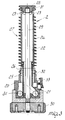
- figure 1 is a longitudinal sectional view of the heat exchanger according to the invention wherein the module comprising the oxygenation apparatus and the blood circuit of the heat exchanger and the module comprising the manifold are associated;
- figure 2 is a longitudinal sectional view of the module comprising the oxygenation apparatus and blood circuit of the heat exchanger;
- figure 3 is a longitudinal sectional view of the module comprising the manifold;
- figure 4 is a schematic exploded view of the shell, the core, and the manifold with discordant helical corrugations which can be seen in figures 1 through 3;
- figure 5 is a schematic view of the shell, the core, and the manifold according to an alternative embodiment of the present invention with concordant helical corrugations.
- the reference numerals 1 and 2 respectively, designate a first disposable module comprising the mass transfer means, typically an oxygenation apparatus, and the blood circuit of the heat exchanger and a second module comprising the water distributor or manifold of the heat exchanger. These modules, 1 and 2, when assembled together, produce the blood oxygenation apparatus with heat exchanger shown in figure 1.
- oxygenation/heat exchanger 1 is a single-use module, whereas manifold 2 can be used repeatedly. Therefore, manifold 2 is normally connected to a fixed support, and removable oxygenation/heat exchanger modules 1 are coupled with it. Typically, an oxygenation/heat exchanger 1 is locked in a removable manner at the beginning of an operation and is removed and discarded at the end of the operation.
- the blood circuit of integrally constructed module 1 includes a hollow and substantially cylindrical shell 3, having an interior surface with left-handed, multiple-start, helical corrugations 3a.
- Figure 4 shows the helical corrugations 3a having four starts.
- a tube or core 4 is coaxially aligned within shell 3 and its wall is shaped so as to form right-handed, helical corrugations 4a with four starts, and is made of a material which is a good heat conductor, for example, steel.
- a first annular chamber 5 is thus formed between the interior surface of shell 3 and corrugated outer surface of core 4.
- Chamber 5 is closed by a first sealing means at its upper and lower ends. The upper end is closed by an O-ring sealing gasket 6, interposed between core 4 and shell 5.
- Chamber 5 is closed at its lower end by a double seal formed by O-ring gasket 7, interposed between core 4 and the internal wall of a head 8a (which will be described in detail hereinafter), and by a potted polyurethane resin ring 7a.
- Ring 7a is located in a channel at the lower end of head 8a and the end of core 4 is embedded therein. Ring 7a also provides stability to core 4.
- core 4 and the internal surface of shell 3 both have slight tapers from top to bottom.
- the crests or outer periphery of the corrugations of the outer surface of core 4 contact at one or more points the corrugations of the internal surface of shell 3 due to the discordant orientation of the core 4 and shell 3 corrugations. These points of contact correctly position the core 4 within the shell 3.
- the outer periphery of the corrugations on the exterior surface of the manifold 2 may contact at one or more points the corrugations of the corrugated inner surface of core 4 due to the discordant orientation of manifold 2 and core 4.
- the discordant helical corrugations create an intense turbulence of the blood, preventing the formation of boundary layers, which limit heat transfer, of the blood volume passing through chamber 5.
- External body 11 is monolithically associated with shell 3 by means of heads 8a and 8b. External body 11 is coaxial to shell 3.
- the annular portion of space between body 11 and shell 3 contains hollow fibers 12 having an inner and outer surface, which are embedded at each end of body 11 in polyurethane resin rings 13 and 14, by a process known as potting.
- oxygen flows through fibers 12 some of the oxygen passes through the microporous membrane which constitutes the wall of fibers 12 and is absorbed into the blood flowing over fibers 12.
- the blood leaves the annular portion of space through connector 15 which is monolithically formed in body 11, along the direction of the arrow F2 of figure 1.
- Oxygen is supplied to hollow fibers 12 through hole 16 formed within head 8b.
- the part of the oxygen which does not pass into the blood through the walls of fibers 12 reaches section 17, which is provided with output connector 18.
- Manifold 2 of the device is now described with particular reference to figure 3.
- Manifold 2 is inserted in the internal cavity of module 1 , i.e., coaxially aligned within core 4, as shown i figure 1.
- the external surface of manifold 2 is provided with left-handed, two-start, helical corrugations 2a.
- a second annular chamber 19 is defined by the helical corrugated exterior surface of manifold 2 and the corrugated inner surface of core 4.
- the discordant helical corrugations 2a (left-handed) and 4a (right-handed) create an intense turbulence in the water flow, preventing the formation of boundary layers, which limit heat transfer, for the water volume passing through water chamber 19.
- base 20 includes connector 21 for water entry along the direction indicated by the arrow F3.
- Connector 21 is connected to inlet duct 22 which extends axially inside manifold 2 and reaches the upper end, where openings 23 connect duct 22 with water chamber 19, all forming a second fluid inlet means.
- Base 20 also includes connector 24 for water discharge along the direction indicated by the arrow F4.
- Connector 24 is connected to duct 25, which is coaxial to duct 22. Openings 26 connect duct 25 with water chamber 19, forming a second fluid outlet means. Therefore, water entering from connector 21 passes through duct 22 in an upward direction, then passes, by means of openings 23, into water chamber 19 and flows downward through chamber 19, passing along the inner surface of tube 4 in the opposite direction of the blood which flows through chamber 5 in an upward direction and passing along the outer surface of tube 4, effectively exchanging heat. Finally, the water enters duct 25 by means of openings 26, and flows into the outlet connector 24.
- Water chamber 19 is closed at each end by a second sealing means including gaskets which must be able to expand to provide watertightness during the operation of the device and must contract when a module 1 is inserted or removed.
- manifold 2 includes, adjacent to base 20, section 27 on which washer 28 is superimposed. Washer 28 is shaped complementarily to stem 29 which is threaded at its end and extends from knob 30.
- Section 27 includes the external surface with helical corrugations 2a, openings 23 and openings 26.
- O-ring gaskets 31a, 32a are provided in seats 31 and 32, respectively, which are formed between section 27 and washer 28 and between section 27 and base 20, respectively.
- Knob 30 can be activated to compress gasket 31a, 32a to cause expansion in contact with the circumferential bands, respectively, 4b and 4c, of core 4 when the device is to be used and watertightness is essential, or can be released in order to remove module 1.
- a removable locking means allows for the selective removal or attachment of disposable module 1 to manifold 2.
- Base 20 includes a plurality of pivoting claws 33 which are manually activated to release from or lock into groove 34 in head 8a.
- a spring mechanism could be used to activate claws 33.
- the present invention incorporates the fluid-dynamic advantages of the helically corrugated chamber walls, effectuating an improved heat transfer characteristic. Further, the present invention reduces the need for priming which allows for a compact, easy-to-handle device that is desirable in the operating room environment.
- figure 5 is a view of a shell 35, core 36, and manifold 37 which have helical corrugations, respectively 35a, 36a, 37a, which have concordant left-handed orientations.
- the water distributor 2 and core corrugations 4a are left-handed whereas the shell corrugations 3a are right-handed.
- core 4 and interior surface of the shell 3 have a slight taper.
- both core 4 and shell surface may be perfectly cylindrical, and in this case appropriate references for correct mutual assembly are provided. Further, other fluids with good heat exchange characteristics can be used to replace water.
- heat exchanger might be inserted in oxygenation apparatuses or other mass transfer devices whose general structure is different from the one described, and that the heat exchanger may also be used as an independent unit.
Abstract
Description
- The present invention relates to a heat exchanger in an extracorporeal blood circuit.
- It is known that extracorporeal blood circuits are created during surgery. The circuits typically include a heat exchanger in which the blood exchanges heat with a fluid (usually water) to regulate blood temperature, and a mass transfer device such as an oxygenation apparatus which supplies oxygen to the blood. Frequently, the oxygenation apparatus and the heat exchanger are combined in a single device.
- A common embodiment of known heat exchangers provides for the flow of blood and water in respective contiguous interspaces or chambers. Also, exchangers are known in which one wall of the chamber or interspace is corrugated, whereas the other one is smooth. An example of such a heat exchanger is one in which the blood circuit is provided in a single-use module which is removably associated with a water distributor or manifold designed for continued use.
- The above-described configuration leads to disadvantageous performance, since the blood undergoes heavy load losses, i.e., a pressure differential between the blood entering and exiting the device, with the danger of damaging the blood. In order to reduce these load losses it is necessary to resort to configurations which increase priming, i.e., the amount of blood contained in the device. Increased priming adds further negative attributes to the heat exchanger including a reduced circulation rate of the blood through the device causing stagnation and clotting of the blood.
- For these reasons, known heat exchangers are not fully satisfactory and are not suited to be reduced in size so that they can be coupled to so-called infant or neonatal oxygenation apparatuses to be used with patients having an extremely low weight, with the necessary miniaturization. In these situations the patients have a small blood supply that cannot be used to prime the heat exchanger. Therefore, a solution or donor blood must be used to prime the heat exchanger which is generally recognized as an undesirable situation. Also, prior art combinations of a heat exchanger and an oxygenation apparatus in a single device provides a bulky and often unwieldy structure.
- An object of the present invention is to provide a heat exchanger in an extracorporeal blood circuit which exploits fluid-dynamic characteristics for improved heat exchange, in conjunction with a low priming requirement, so that the heat exchanger can be coupled advantageously to infant and neonatal oxygenation apparatuses.
- A further object of the present invention is to provide a heat exchanger in an extracorporeal blood circuit which can be associated with an oxygenation apparatus in a compact system, minimizing bulk and facilitating the handling of the system.
- The above objects are achieved by a heat exchanger in an extracorporeal blood circuit, according to the invention, having a cylindrical shell with a corrugated interior surface, a core having an inner and outer corrugated surface coaxially aligned within the shell, the outer surface of the core and the interior surface of the shell forming a first annular chamber. Further, a manifold is coaxially aligned within the core, and the corrugated exterior surface of the manifold and inner surface of the core form a second annular chamber, so that blood passes through the first chamber and water passes through the second chamber so that heat is exchanged across the core, thereby regulating the temperature of the blood.
- The invention relates to an improved heat exchanger associated with a hollow-fiber oxygenation apparatus or other mass transfer means. The oxygenation apparatus includes a coaxial external body monolithically associated with the substantially cylindrical shell, by means of two end heads, with the interposition of an annular portion of space containing hollow fibers. The hollow fibers are embedded at the ends of the external body in rings of polyurethane resin, termed potting. The annular portion of space is connected, at one hand, to openings for the exit of the blood from the first annular chamber and, at the other end, with a blood exit connector. The first head comprises an oxygen inlet section and the second head comprises at least an oxygen outlet section.
- Further characteristics and advantages will become apparent from the description of a preferred, but not exclusive, embodiment of the invention, illustrated only by way of example in the accompanying drawings, wherein:
figure 1 is a longitudinal sectional view of the heat exchanger according to the invention wherein the module comprising the oxygenation apparatus and the blood circuit of the heat exchanger and the module comprising the manifold are associated;
figure 2 is a longitudinal sectional view of the module comprising the oxygenation apparatus and blood circuit of the heat exchanger;
figure 3 is a longitudinal sectional view of the module comprising the manifold;
figure 4 is a schematic exploded view of the shell, the core, and the manifold with discordant helical corrugations which can be seen in figures 1 through 3;
figure 5 is a schematic view of the shell, the core, and the manifold according to an alternative embodiment of the present invention with concordant helical corrugations. - With reference to the above figures 1 to 4, the
reference numerals - In the preferred embodiment of the invention, oxygenation/
heat exchanger 1 is a single-use module, whereasmanifold 2 can be used repeatedly. Therefore,manifold 2 is normally connected to a fixed support, and removable oxygenation/heat exchanger modules 1 are coupled with it. Typically, an oxygenation/heat exchanger 1 is locked in a removable manner at the beginning of an operation and is removed and discarded at the end of the operation. - The blood circuit of integrally constructed
module 1 includes a hollow and substantiallycylindrical shell 3, having an interior surface with left-handed, multiple-start, helical corrugations 3a. Figure 4 shows the helical corrugations 3a having four starts. - A tube or
core 4 is coaxially aligned withinshell 3 and its wall is shaped so as to form right-handed,helical corrugations 4a with four starts, and is made of a material which is a good heat conductor, for example, steel. A firstannular chamber 5 is thus formed between the interior surface ofshell 3 and corrugated outer surface ofcore 4.Chamber 5 is closed by a first sealing means at its upper and lower ends. The upper end is closed by an O-ring sealing gasket 6, interposed betweencore 4 andshell 5.Chamber 5 is closed at its lower end by a double seal formed by O-ring gasket 7, interposed betweencore 4 and the internal wall of a head 8a (which will be described in detail hereinafter), and by a potted polyurethane resin ring 7a. Ring 7a is located in a channel at the lower end of head 8a and the end ofcore 4 is embedded therein. Ring 7a also provides stability tocore 4. - As shown in figures 1 and 2,
core 4 and the internal surface ofshell 3 both have slight tapers from top to bottom. During assembly, the crests or outer periphery of the corrugations of the outer surface ofcore 4 contact at one or more points the corrugations of the internal surface ofshell 3 due to the discordant orientation of thecore 4 andshell 3 corrugations. These points of contact correctly position thecore 4 within theshell 3. Also, the outer periphery of the corrugations on the exterior surface of themanifold 2 may contact at one or more points the corrugations of the corrugated inner surface ofcore 4 due to the discordant orientation ofmanifold 2 andcore 4. - Blood enters
chamber 5 through aconnector 9 located within head 8a in the direction indicated by the arrow F1 of figure 1 forming a first fluid inlet means, and leavesblood chamber 5 throughopenings 10, forming a first fluid outlet means. As blood travels throughchamber 5, the discordant helical corrugations create an intense turbulence of the blood, preventing the formation of boundary layers, which limit heat transfer, of the blood volume passing throughchamber 5. -
External body 11 is monolithically associated withshell 3 by means of heads 8a and 8b.External body 11 is coaxial toshell 3. The annular portion of space betweenbody 11 andshell 3 containshollow fibers 12 having an inner and outer surface, which are embedded at each end ofbody 11 inpolyurethane resin rings -
Blood exits chamber 5 and enters the annular portion of space of the mass transfer means throughopenings 10, flowing overfibers 12 and absorbing oxygen or an oxygen-containing gas. As oxygen flows throughfibers 12, some of the oxygen passes through the microporous membrane which constitutes the wall offibers 12 and is absorbed into the blood flowing overfibers 12. The blood leaves the annular portion of space throughconnector 15 which is monolithically formed inbody 11, along the direction of the arrow F2 of figure 1. - Oxygen is supplied to
hollow fibers 12 throughhole 16 formed within head 8b. The part of the oxygen which does not pass into the blood through the walls offibers 12 reachessection 17, which is provided withoutput connector 18. - The
manifold 2 of the device is now described with particular reference to figure 3. Manifold 2 is inserted in the internal cavity ofmodule 1 , i.e., coaxially aligned withincore 4, as shown i figure 1. The external surface ofmanifold 2 is provided with left-handed, two-start, helical corrugations 2a. A secondannular chamber 19 is defined by the helical corrugated exterior surface ofmanifold 2 and the corrugated inner surface ofcore 4. As water flows throughchamber 19, the discordant helical corrugations 2a (left-handed) and 4a (right-handed) create an intense turbulence in the water flow, preventing the formation of boundary layers, which limit heat transfer, for the water volume passing throughwater chamber 19. - At the lower end of
manifold 2,base 20 includesconnector 21 for water entry along the direction indicated by the arrow F3.Connector 21 is connected toinlet duct 22 which extends axially insidemanifold 2 and reaches the upper end, whereopenings 23 connectduct 22 withwater chamber 19, all forming a second fluid inlet means. -
Base 20 also includesconnector 24 for water discharge along the direction indicated by the arrow F4.Connector 24 is connected toduct 25, which is coaxial toduct 22.Openings 26 connectduct 25 withwater chamber 19, forming a second fluid outlet means. Therefore, water entering fromconnector 21 passes throughduct 22 in an upward direction, then passes, by means ofopenings 23, intowater chamber 19 and flows downward throughchamber 19, passing along the inner surface oftube 4 in the opposite direction of the blood which flows throughchamber 5 in an upward direction and passing along the outer surface oftube 4, effectively exchanging heat. Finally, the water entersduct 25 by means ofopenings 26, and flows into theoutlet connector 24. -
Water chamber 19 is closed at each end by a second sealing means including gaskets which must be able to expand to provide watertightness during the operation of the device and must contract when amodule 1 is inserted or removed. For this purpose,manifold 2 includes, adjacent tobase 20,section 27 on whichwasher 28 is superimposed.Washer 28 is shaped complementarily to stem 29 which is threaded at its end and extends fromknob 30.Section 27 includes the external surface with helical corrugations 2a,openings 23 andopenings 26. - O-
ring gaskets 31a, 32a are provided inseats section 27 andwasher 28 and betweensection 27 andbase 20, respectively.Knob 30 can be activated to compressgasket 31a, 32a to cause expansion in contact with the circumferential bands, respectively, 4b and 4c, ofcore 4 when the device is to be used and watertightness is essential, or can be released in order to removemodule 1. - It should be noted that the provision of independent gaskets for
blood chamber 5 andwater chamber 19 ensures that any leakage of one of the gaskets does not cause the mixing of the blood and water, and fluid (blood or water) simply leaks outward. - As shown in figure 1, a removable locking means allows for the selective removal or attachment of
disposable module 1 tomanifold 2.Base 20 includes a plurality of pivotingclaws 33 which are manually activated to release from or lock intogroove 34 in head 8a. Alternatively, a spring mechanism could be used to activateclaws 33. - The present invention incorporates the fluid-dynamic advantages of the helically corrugated chamber walls, effectuating an improved heat transfer characteristic. Further, the present invention reduces the need for priming which allows for a compact, easy-to-handle device that is desirable in the operating room environment.
- The present invention is susceptible to numerous modifications and variations, all of which are within the scope of the inventive concept. Thus, for example, figure 5 is a view of a
shell 35,core 36, andmanifold 37 which have helical corrugations, respectively 35a, 36a, 37a, which have concordant left-handed orientations. In other embodiments, for example, thewater distributor 2 andcore corrugations 4a are left-handed whereas the shell corrugations 3a are right-handed. - It is furthermore obvious that the number of starts of the helical corrugations may vary. The same is true for the method of providing the seals at the ends of the blood and water chambers.
- In the preferred embodiment,
core 4 and interior surface of theshell 3 have a slight taper. According to another embodiment, bothcore 4 and shell surface may be perfectly cylindrical, and in this case appropriate references for correct mutual assembly are provided. Further, other fluids with good heat exchange characteristics can be used to replace water. - Finally, it should be noted that the heat exchanger according to the invention might be inserted in oxygenation apparatuses or other mass transfer devices whose general structure is different from the one described, and that the heat exchanger may also be used as an independent unit.
- In the practical embodiment of the invention, all the details may be replaced with other technically equivalent elements. Also, the materials employed, as well as the shapes and dimensions, may vary.
- Where technical features mentioned in any claim are followed by reference signs, such reference signs have been included for the sole purpose of increasing the intelligibility of the claims and accordingly such reference signs do not have any limiting effect on the scope of each element identified by way of example by such reference signs.
Claims (15)
- A device for mass transfer and heat exchange, characterized in that it comprises:- a cylindrical shell having a corrugated interior surface;- a core having a corrugated inner and corrugated outer surface, the core being coaxially aligned within the cylindrical shell, wherein the interior surface of the cylindrical shell is opposed to the outer surface of the core to form a first annular chamber;- a manifold having a corrugated exterior surface, the manifold being coaxially aligned within the core, wherein the exterior surface of the manifold is opposed to the inner surface of the core to form a second annular chamber;- a first fluid inlet means for introducing a first fluid into the first annular chamber and a first fluid outlet means for discharging the first fluid from the first annular chamber, wherein the first fluid inlet means and first fluid outlet means are opposed axially at opposite ends of the first annular chamber for passing the first fluid axially through the first annular chamber;- a second fluid inlet means for introducing a second fluid for heat exchange into the second annular chamber and a second fluid outlet means for discharging the second fluid from the second annular chamber, wherein the second fluid inlet means and second fluid outlet means are opposed axially at opposite ends of the second annular chamber for passing the second fluid axially through the second annular chamber, wherein heat exchange occurs across the core between the first and second fluid.
- The device of claim 1, characterized in that the corrugated interior surface of the cylindrical shell, the inner and outer surfaces of the core, and the corrugated exterior surface of the manifold each have helical corrugations.
- The device of claim 2, characterized in that the corrugated outer surface of the core is discordant with the corrugated interior surface of the cylindrical shell.
- The device of claim 2, characterized in that the corrugated inner surface of the core is discordant with the corrugated exterior surface of the manifold.
- The device of claim 2, characterized in that the corrugated outer surface of the core is concordant with the corrugated interior surface of the cylindrical shell.
- The device of claim 2, characterized in that the corrugated inner surface of the core is concordant with the corrugated exterior surface of the manifold.
- The device of claim 1, characterized in that the first fluid inlet means and second fluid inlet means are axially opposed at opposite ends of the core.
- The device of claim 1, characterized in that the first fluid outlet means and second fluid outlet means are axially opposed at opposite ends of the core.
- The device of claim 1, characterized in that the cylindrical shell and corrugated core are integrally constructed to form a disposable module.
- The device of claim 9, characterized in that the disposable module is removably coupled to the manifold.
- The device of claim 1, characterized in that the outer periphery of at least one corrugation of the corrugated interior surface of the cylindrical shell is in contact with the corrugated outer surface of the core, and the outer periphery of at least one corrugation of the corrugated exterior surface of the manifold is in contact with the corrugated inner surface of the core.
- The device of claim 1, characterized in that it further comprises a first and a second sealing gasket for sealing a first and a second end, respectively, of the first annular chamber, and a third and a fourth sealing gasket for sealing a first and a second end, respectively, of the second annular chamber.
- The device of claim 1, characterized in that the first fluid is blood and the second fluid is water.
- The device of claim 1, characterized in that it further comprises a mass transfer means having an inner surface and an outer surface, the first fluid outlet means being in fluid communication with the outer surface of the mass transfer means, and a third fluid inlet and a third fluid outlet in fluid communication with the inner surface of the mass transfer means; mass transfer occurs between the first fluid and a third fluid passing within the inner surface of the mass transfer means.
- The device of claim 14, characterized in that the mass transfer means comprises a blood oxygenator, the first fluid inlet is a blood inlet, the first fluid outlet is a blood outlet, the second fluid inlet is a water inlet, the second fluid outlet is a water outlet, the third fluid inlet is an oxygen inlet, and the third fluid outlet is an oxygen outlet.
Applications Claiming Priority (2)
| Application Number | Priority Date | Filing Date | Title |
|---|---|---|---|
| ITMI921975A IT1255820B (en) | 1992-08-10 | 1992-08-10 | HEAT EXCHANGER IN EXTRACORPOREAL BLOOD CIRCUIT |
| ITMI921975 | 1992-08-10 |
Publications (2)
| Publication Number | Publication Date |
|---|---|
| EP0582959A1 true EP0582959A1 (en) | 1994-02-16 |
| EP0582959B1 EP0582959B1 (en) | 1998-04-29 |
Family
ID=11363864
Family Applications (1)
| Application Number | Title | Priority Date | Filing Date |
|---|---|---|---|
| EP93112494A Expired - Lifetime EP0582959B1 (en) | 1992-08-10 | 1993-08-04 | Heat exchanger in an extracorporeal blood circuit |
Country Status (6)
| Country | Link |
|---|---|
| EP (1) | EP0582959B1 (en) |
| AT (1) | ATE165518T1 (en) |
| DE (1) | DE69318229T2 (en) |
| DK (1) | DK0582959T3 (en) |
| ES (1) | ES2114980T3 (en) |
| IT (1) | IT1255820B (en) |
Cited By (13)
| Publication number | Priority date | Publication date | Assignee | Title |
|---|---|---|---|---|
| WO1997033636A1 (en) * | 1996-01-11 | 1997-09-18 | Medtronic, Inc. | Blood oxygenator with heat exchanger |
| WO1997034647A1 (en) * | 1996-03-18 | 1997-09-25 | Medtronic, Inc. | Blood oxygenator with waterless heat exchanger |
| US5823987A (en) * | 1996-01-11 | 1998-10-20 | Medtronic, Inc. | Compact membrane-type blood oxygenator with concentric heat exchanger |
| EP1011745A1 (en) * | 1996-11-07 | 2000-06-28 | C.R. Bard Inc. | Integrated oxygenator and heat exchanger |
| EP2420262A1 (en) * | 2010-08-19 | 2012-02-22 | Sorin Group Italia S.r.l. | Blood processing unit with modified flow path |
| US8318092B2 (en) | 2010-04-29 | 2012-11-27 | Sorin Group Italia S.R.L. | Oxygenator with integrated arterial filter |
| US8388566B2 (en) | 2010-04-29 | 2013-03-05 | Sorin Group Italia, S.r.l. | Oxygenator with integrated arterial filter including filter frame |
| US8980176B2 (en) | 2010-08-20 | 2015-03-17 | Sorin Group Italia S.R.L. | Blood processing unit with cross blood flow |
| JP2016039995A (en) * | 2015-11-18 | 2016-03-24 | ソリン・グループ・イタリア・ソシエタ・ア・レスポンサビリタ・リミタータ | Blood processing unit with changed channel |
| JP2017507686A (en) * | 2014-01-09 | 2017-03-23 | ソリン・グループ・イタリア・ソシエタ・ア・レスポンサビリタ・リミタータSorin Group Italia S.r.l. | Blood processing unit having a heat exchanger core forming a modified flow path |
| US10369262B2 (en) | 2014-02-28 | 2019-08-06 | Sorin Group Italia S.R.L. | System for providing an integrated arterial filter into an oxygenator, minimizing added priming volume |
| US10661004B2 (en) | 2015-05-12 | 2020-05-26 | Sorin Group Italia S.R.L. | Blood gas exchanger with restriction element or elements to reduce gas exchange |
| US10814056B2 (en) | 2014-11-12 | 2020-10-27 | Sorin Group Italia S.R.L. | Elastic protection tube for a hollow fiber blood processing apparatus |
Families Citing this family (1)
| Publication number | Priority date | Publication date | Assignee | Title |
|---|---|---|---|---|
| CN109224163B (en) * | 2018-10-16 | 2019-06-21 | 广东工业大学 | A kind of hollow fiber membrane oxygenator that heat exchange layers are external |
Citations (5)
| Publication number | Priority date | Publication date | Assignee | Title |
|---|---|---|---|---|
| FR2091563A5 (en) * | 1970-05-14 | 1972-01-14 | Polystan Ved Kyvsgaard | |
| US4374088A (en) * | 1980-03-03 | 1983-02-15 | Gambro Heart-Lung Products Ab | Apparatus for the transfer of one or more substances between a gas and a liquid |
| EP0089748A2 (en) * | 1982-02-22 | 1983-09-28 | CD Medical, Inc. | Rigid shell expansible blood reservoir, heater and hollow fibre membrane oxygenator assembly |
| EP0114732A2 (en) * | 1983-01-14 | 1984-08-01 | Baxter Travenol Laboratories, Inc. | Blood oxygenator |
| WO1991006327A1 (en) * | 1989-10-26 | 1991-05-16 | Baxter International Inc. | Blood oxygenation system |
-
1992
- 1992-08-10 IT ITMI921975A patent/IT1255820B/en active IP Right Grant
-
1993
- 1993-08-04 DE DE69318229T patent/DE69318229T2/en not_active Expired - Lifetime
- 1993-08-04 DK DK93112494T patent/DK0582959T3/en active
- 1993-08-04 AT AT93112494T patent/ATE165518T1/en not_active IP Right Cessation
- 1993-08-04 ES ES93112494T patent/ES2114980T3/en not_active Expired - Lifetime
- 1993-08-04 EP EP93112494A patent/EP0582959B1/en not_active Expired - Lifetime
Patent Citations (5)
| Publication number | Priority date | Publication date | Assignee | Title |
|---|---|---|---|---|
| FR2091563A5 (en) * | 1970-05-14 | 1972-01-14 | Polystan Ved Kyvsgaard | |
| US4374088A (en) * | 1980-03-03 | 1983-02-15 | Gambro Heart-Lung Products Ab | Apparatus for the transfer of one or more substances between a gas and a liquid |
| EP0089748A2 (en) * | 1982-02-22 | 1983-09-28 | CD Medical, Inc. | Rigid shell expansible blood reservoir, heater and hollow fibre membrane oxygenator assembly |
| EP0114732A2 (en) * | 1983-01-14 | 1984-08-01 | Baxter Travenol Laboratories, Inc. | Blood oxygenator |
| WO1991006327A1 (en) * | 1989-10-26 | 1991-05-16 | Baxter International Inc. | Blood oxygenation system |
Cited By (27)
| Publication number | Priority date | Publication date | Assignee | Title |
|---|---|---|---|---|
| WO1997033636A1 (en) * | 1996-01-11 | 1997-09-18 | Medtronic, Inc. | Blood oxygenator with heat exchanger |
| US5823987A (en) * | 1996-01-11 | 1998-10-20 | Medtronic, Inc. | Compact membrane-type blood oxygenator with concentric heat exchanger |
| EP1371381A1 (en) * | 1996-01-11 | 2003-12-17 | Medtronic, Inc. | Blood oxygenator with heat exchanger |
| WO1997034647A1 (en) * | 1996-03-18 | 1997-09-25 | Medtronic, Inc. | Blood oxygenator with waterless heat exchanger |
| US6045752A (en) * | 1996-03-18 | 2000-04-04 | Medtronic, Inc. | Blood oxygenator with waterless heat exchanger |
| EP1011745A1 (en) * | 1996-11-07 | 2000-06-28 | C.R. Bard Inc. | Integrated oxygenator and heat exchanger |
| EP1011745A4 (en) * | 1996-11-07 | 2000-08-09 | Bard Inc C R | Integrated oxygenator and heat exchanger |
| US9162022B2 (en) | 2010-04-29 | 2015-10-20 | Politecnico Di Milano | Oxygenator with integrated arterial filter including filter frame |
| US8318092B2 (en) | 2010-04-29 | 2012-11-27 | Sorin Group Italia S.R.L. | Oxygenator with integrated arterial filter |
| US8388566B2 (en) | 2010-04-29 | 2013-03-05 | Sorin Group Italia, S.r.l. | Oxygenator with integrated arterial filter including filter frame |
| US8652406B2 (en) | 2010-08-19 | 2014-02-18 | Sorin Group Italia S.R.L. | Blood processing unit with modified flow path |
| EP2612685A1 (en) * | 2010-08-19 | 2013-07-10 | Sorin Group Italia S.r.l. | Blood processing unit with modified flow path |
| US8394049B2 (en) | 2010-08-19 | 2013-03-12 | Sorin Group Italia S.R.L. | Blood processing unit with modified flow path |
| US8795220B2 (en) | 2010-08-19 | 2014-08-05 | Politecnico Di Milano | Blood processing unit with circumferential blood flow |
| EP2420262A1 (en) * | 2010-08-19 | 2012-02-22 | Sorin Group Italia S.r.l. | Blood processing unit with modified flow path |
| US11160912B2 (en) | 2010-08-19 | 2021-11-02 | Sorin Group Italia S.R.L. | Blood processing unit with modified flow path |
| US9402943B2 (en) | 2010-08-19 | 2016-08-02 | Sorin Group Italia S.R.L. | Blood processing unit with modified flow path |
| US10159777B2 (en) | 2010-08-19 | 2018-12-25 | Sorin Group Italia S.R.L. | Blood processing unit with modified flow path |
| US8980176B2 (en) | 2010-08-20 | 2015-03-17 | Sorin Group Italia S.R.L. | Blood processing unit with cross blood flow |
| US10098994B2 (en) | 2014-01-09 | 2018-10-16 | Sorin Group Italia S.R.L. | Blood processing unit with heat exchanger core for providing modified flow path |
| JP2017507686A (en) * | 2014-01-09 | 2017-03-23 | ソリン・グループ・イタリア・ソシエタ・ア・レスポンサビリタ・リミタータSorin Group Italia S.r.l. | Blood processing unit having a heat exchanger core forming a modified flow path |
| USRE49759E1 (en) | 2014-01-09 | 2023-12-19 | Sorin Group Italia S.R.L. | Blood processing unit with heat exchanger core for providing modified flow path |
| US10369262B2 (en) | 2014-02-28 | 2019-08-06 | Sorin Group Italia S.R.L. | System for providing an integrated arterial filter into an oxygenator, minimizing added priming volume |
| US11471577B2 (en) | 2014-02-28 | 2022-10-18 | Sorin Group S.r.l. | System for providing an integrated arterial filter into an oxygenator, minimizing added priming volume |
| US10814056B2 (en) | 2014-11-12 | 2020-10-27 | Sorin Group Italia S.R.L. | Elastic protection tube for a hollow fiber blood processing apparatus |
| US10661004B2 (en) | 2015-05-12 | 2020-05-26 | Sorin Group Italia S.R.L. | Blood gas exchanger with restriction element or elements to reduce gas exchange |
| JP2016039995A (en) * | 2015-11-18 | 2016-03-24 | ソリン・グループ・イタリア・ソシエタ・ア・レスポンサビリタ・リミタータ | Blood processing unit with changed channel |
Also Published As
| Publication number | Publication date |
|---|---|
| ATE165518T1 (en) | 1998-05-15 |
| EP0582959B1 (en) | 1998-04-29 |
| ITMI921975A1 (en) | 1994-02-10 |
| DK0582959T3 (en) | 1999-02-15 |
| DE69318229T2 (en) | 1998-08-27 |
| DE69318229D1 (en) | 1998-06-04 |
| IT1255820B (en) | 1995-11-16 |
| ITMI921975A0 (en) | 1992-08-10 |
| ES2114980T3 (en) | 1998-06-16 |
Similar Documents
| Publication | Publication Date | Title |
|---|---|---|
| EP0582959B1 (en) | Heat exchanger in an extracorporeal blood circuit | |
| US4231425A (en) | Extracorporeal circuit blood heat exchanger | |
| US4065264A (en) | Blood oxygenator with integral heat exchanger for regulating the temperature of blood in an extracorporeal circuit | |
| US4138288A (en) | Method and apparatus for oxygenating and regulating the temperature of blood | |
| US4451562A (en) | Blood oxygenator | |
| US5236586A (en) | Apparatus for the treatment of fluids | |
| EP0046583B1 (en) | Hollow fiber-type artificial lung having enclosed heat exchanger | |
| CA1333554C (en) | Integrated membrane blood oxygenator/heat exchanger | |
| US5124127A (en) | Hollow fiber blood oxygenator | |
| US5217689A (en) | Blood oxygenation system | |
| US4657743A (en) | Heat exchanger-incorporated hollow fiber type artifical lung | |
| US5674452A (en) | Hollow fiber exchangers | |
| US3998593A (en) | Membrane blood oxygenator | |
| US4138464A (en) | Blood oxygenator with integral heat exchanger | |
| US7297255B2 (en) | Mass or energy transfer cartridge and module | |
| EP0408000A1 (en) | Fluid processing apparatus | |
| US5762869A (en) | Blood oxygenator | |
| US5058661A (en) | Heat exchanger with leakage collector | |
| US4818490A (en) | Integral blood oxygenator | |
| US5240677A (en) | Hollow fiber blood oxygenator | |
| US4645645A (en) | Oxygenator having an improved heat exchanger | |
| JPS6339262B2 (en) | ||
| US5395468A (en) | Method of construction of a mass transfer device | |
| US4160801A (en) | Heat exchanger-blood oxygenator combination | |
| US4640773A (en) | Membrane separation apparatus |
Legal Events
| Date | Code | Title | Description |
|---|---|---|---|
| PUAI | Public reference made under article 153(3) epc to a published international application that has entered the european phase |
Free format text: ORIGINAL CODE: 0009012 |
|
| AK | Designated contracting states |
Kind code of ref document: A1 Designated state(s): AT BE CH DE DK ES FR GB IT LI NL SE |
|
| 17P | Request for examination filed |
Effective date: 19940725 |
|
| 17Q | First examination report despatched |
Effective date: 19960320 |
|
| GRAG | Despatch of communication of intention to grant |
Free format text: ORIGINAL CODE: EPIDOS AGRA |
|
| GRAG | Despatch of communication of intention to grant |
Free format text: ORIGINAL CODE: EPIDOS AGRA |
|
| GRAH | Despatch of communication of intention to grant a patent |
Free format text: ORIGINAL CODE: EPIDOS IGRA |
|
| GRAH | Despatch of communication of intention to grant a patent |
Free format text: ORIGINAL CODE: EPIDOS IGRA |
|
| GRAA | (expected) grant |
Free format text: ORIGINAL CODE: 0009210 |
|
| AK | Designated contracting states |
Kind code of ref document: B1 Designated state(s): AT BE CH DE DK ES FR GB IT LI NL SE |
|
| PG25 | Lapsed in a contracting state [announced via postgrant information from national office to epo] |
Ref country code: LI Free format text: LAPSE BECAUSE OF FAILURE TO SUBMIT A TRANSLATION OF THE DESCRIPTION OR TO PAY THE FEE WITHIN THE PRESCRIBED TIME-LIMIT Effective date: 19980429 Ref country code: CH Free format text: LAPSE BECAUSE OF FAILURE TO SUBMIT A TRANSLATION OF THE DESCRIPTION OR TO PAY THE FEE WITHIN THE PRESCRIBED TIME-LIMIT Effective date: 19980429 |
|
| REF | Corresponds to: |
Ref document number: 165518 Country of ref document: AT Date of ref document: 19980515 Kind code of ref document: T |
|
| REG | Reference to a national code |
Ref country code: CH Ref legal event code: EP |
|
| ET | Fr: translation filed | ||
| REF | Corresponds to: |
Ref document number: 69318229 Country of ref document: DE Date of ref document: 19980604 |
|
| REG | Reference to a national code |
Ref country code: ES Ref legal event code: FG2A Ref document number: 2114980 Country of ref document: ES Kind code of ref document: T3 |
|
| ITF | It: translation for a ep patent filed |
Owner name: MODIANO & ASSOCIATI S.R.L. |
|
| PG25 | Lapsed in a contracting state [announced via postgrant information from national office to epo] |
Ref country code: SE Free format text: LAPSE BECAUSE OF FAILURE TO SUBMIT A TRANSLATION OF THE DESCRIPTION OR TO PAY THE FEE WITHIN THE PRESCRIBED TIME-LIMIT Effective date: 19980729 |
|
| REG | Reference to a national code |
Ref country code: CH Ref legal event code: PL |
|
| REG | Reference to a national code |
Ref country code: DK Ref legal event code: T3 |
|
| PLBE | No opposition filed within time limit |
Free format text: ORIGINAL CODE: 0009261 |
|
| STAA | Information on the status of an ep patent application or granted ep patent |
Free format text: STATUS: NO OPPOSITION FILED WITHIN TIME LIMIT |
|
| 26N | No opposition filed | ||
| PGFP | Annual fee paid to national office [announced via postgrant information from national office to epo] |
Ref country code: ES Payment date: 20010709 Year of fee payment: 9 |
|
| PGFP | Annual fee paid to national office [announced via postgrant information from national office to epo] |
Ref country code: AT Payment date: 20010810 Year of fee payment: 9 |
|
| PGFP | Annual fee paid to national office [announced via postgrant information from national office to epo] |
Ref country code: DK Payment date: 20010828 Year of fee payment: 9 |
|
| PGFP | Annual fee paid to national office [announced via postgrant information from national office to epo] |
Ref country code: BE Payment date: 20010829 Year of fee payment: 9 |
|
| REG | Reference to a national code |
Ref country code: GB Ref legal event code: IF02 |
|
| PG25 | Lapsed in a contracting state [announced via postgrant information from national office to epo] |
Ref country code: AT Free format text: LAPSE BECAUSE OF NON-PAYMENT OF DUE FEES Effective date: 20020804 |
|
| PG25 | Lapsed in a contracting state [announced via postgrant information from national office to epo] |
Ref country code: ES Free format text: LAPSE BECAUSE OF NON-PAYMENT OF DUE FEES Effective date: 20020805 |
|
| PG25 | Lapsed in a contracting state [announced via postgrant information from national office to epo] |
Ref country code: DK Free format text: LAPSE BECAUSE OF NON-PAYMENT OF DUE FEES Effective date: 20020831 Ref country code: BE Free format text: LAPSE BECAUSE OF NON-PAYMENT OF DUE FEES Effective date: 20020831 |
|
| BERE | Be: lapsed |
Owner name: *DIDECO S.P.A. Effective date: 20020831 |
|
| REG | Reference to a national code |
Ref country code: DK Ref legal event code: EBP |
|
| REG | Reference to a national code |
Ref country code: ES Ref legal event code: FD2A Effective date: 20030912 |
|
| PGFP | Annual fee paid to national office [announced via postgrant information from national office to epo] |
Ref country code: NL Payment date: 20100810 Year of fee payment: 18 |
|
| PGFP | Annual fee paid to national office [announced via postgrant information from national office to epo] |
Ref country code: DE Payment date: 20100728 Year of fee payment: 18 |
|
| REG | Reference to a national code |
Ref country code: NL Ref legal event code: V1 Effective date: 20120301 |
|
| PG25 | Lapsed in a contracting state [announced via postgrant information from national office to epo] |
Ref country code: NL Free format text: LAPSE BECAUSE OF NON-PAYMENT OF DUE FEES Effective date: 20120301 |
|
| REG | Reference to a national code |
Ref country code: DE Ref legal event code: R119 Ref document number: 69318229 Country of ref document: DE Effective date: 20120301 |
|
| PGFP | Annual fee paid to national office [announced via postgrant information from national office to epo] |
Ref country code: GB Payment date: 20120801 Year of fee payment: 20 |
|
| PGFP | Annual fee paid to national office [announced via postgrant information from national office to epo] |
Ref country code: IT Payment date: 20120809 Year of fee payment: 20 Ref country code: FR Payment date: 20120823 Year of fee payment: 20 |
|
| PG25 | Lapsed in a contracting state [announced via postgrant information from national office to epo] |
Ref country code: DE Free format text: LAPSE BECAUSE OF NON-PAYMENT OF DUE FEES Effective date: 20120301 |
|
| REG | Reference to a national code |
Ref country code: GB Ref legal event code: PE20 Expiry date: 20130803 |
|
| PG25 | Lapsed in a contracting state [announced via postgrant information from national office to epo] |
Ref country code: GB Free format text: LAPSE BECAUSE OF EXPIRATION OF PROTECTION Effective date: 20130803 |