EP0581838B1 - Engine for performing subsea operations and use of it in a core sampler - Google Patents
Engine for performing subsea operations and use of it in a core sampler Download PDFInfo
- Publication number
- EP0581838B1 EP0581838B1 EP92909601A EP92909601A EP0581838B1 EP 0581838 B1 EP0581838 B1 EP 0581838B1 EP 92909601 A EP92909601 A EP 92909601A EP 92909601 A EP92909601 A EP 92909601A EP 0581838 B1 EP0581838 B1 EP 0581838B1
- Authority
- EP
- European Patent Office
- Prior art keywords
- piston
- valve
- low pressure
- sampler
- pressure chamber
- Prior art date
- Legal status (The legal status is an assumption and is not a legal conclusion. Google has not performed a legal analysis and makes no representation as to the accuracy of the status listed.)
- Expired - Lifetime
Links
Images








Classifications
-
- B—PERFORMING OPERATIONS; TRANSPORTING
- B63—SHIPS OR OTHER WATERBORNE VESSELS; RELATED EQUIPMENT
- B63C—LAUNCHING, HAULING-OUT, OR DRY-DOCKING OF VESSELS; LIFE-SAVING IN WATER; EQUIPMENT FOR DWELLING OR WORKING UNDER WATER; MEANS FOR SALVAGING OR SEARCHING FOR UNDERWATER OBJECTS
- B63C11/00—Equipment for dwelling or working underwater; Means for searching for underwater objects
- B63C11/52—Tools specially adapted for working underwater, not otherwise provided for
-
- E—FIXED CONSTRUCTIONS
- E21—EARTH OR ROCK DRILLING; MINING
- E21B—EARTH OR ROCK DRILLING; OBTAINING OIL, GAS, WATER, SOLUBLE OR MELTABLE MATERIALS OR A SLURRY OF MINERALS FROM WELLS
- E21B25/00—Apparatus for obtaining or removing undisturbed cores, e.g. core barrels or core extractors
- E21B25/18—Apparatus for obtaining or removing undisturbed cores, e.g. core barrels or core extractors the core receiver being specially adapted for operation under water
-
- E—FIXED CONSTRUCTIONS
- E21—EARTH OR ROCK DRILLING; MINING
- E21B—EARTH OR ROCK DRILLING; OBTAINING OIL, GAS, WATER, SOLUBLE OR MELTABLE MATERIALS OR A SLURRY OF MINERALS FROM WELLS
- E21B41/00—Equipment or details not covered by groups E21B15/00 - E21B40/00
- E21B41/0007—Equipment or details not covered by groups E21B15/00 - E21B40/00 for underwater installations
-
- E—FIXED CONSTRUCTIONS
- E21—EARTH OR ROCK DRILLING; MINING
- E21B—EARTH OR ROCK DRILLING; OBTAINING OIL, GAS, WATER, SOLUBLE OR MELTABLE MATERIALS OR A SLURRY OF MINERALS FROM WELLS
- E21B7/00—Special methods or apparatus for drilling
- E21B7/12—Underwater drilling
- E21B7/124—Underwater drilling with underwater tool drive prime mover, e.g. portable drilling rigs for use on underwater floors
Definitions
- the invention concerns a machine which is intended to operate at great depths by utilizing the energy which is released when surrounding water masses under great hydrostatic pressure are admitted into a low pressure reservoir via a hydraulic motor, either of the reciprocating or the rotary type, as stated in the introduction of claim 1 and claim 17.
- the invention also concerns a hydrostatic sampler, especially for core samples of marine sediments, wherein the sampler comprises a substantially cylindrical head and a substantially cylindrical sampler section whose longitudinal axis passes approximately through the head's centre of gravity and wherein the sampler section comprises a sampler tube consisting of at least one sampler tube section.
- US-A- 3 418 818 discloses a hydrostatic power source which may be used for supplying power to underwater manipulators and propelling an underwater vehicle.
- US-A- 3 412 814 discloses a hydrostatic corer driven by the pressure differential between the hydrostatic head and a vacuum chamber.
- US-A- 3 436 914 discloses a hydrostatic energy accumulator which also is intended for driving a corer and operates in a comparable manner to the foregoing, while US-A- 4 215 544 discloses a method of generating deepsea rotary power by means of a turbine driven by the hydrostatic pressure differential between the surrounding body of water and an evacuated sphere.
- the reason behind the invention is that the supply of, e.g., hydraulic or electrical power from, e.g., a ship to a working tool on the seabed, entails increasing difficulties as the depth increases, since transmission lines or pipes become extremely expensive, heavy, difficult to handle and vulnerable.
- the machine according to the invention uses an integral low pressure reservoir as a "hydrostatic accumulator", the energy which is released when the surrounding liquid is admitted into the low pressure reservoir under controlled conditions being determined by the product of the pressure difference and the internal volume of the low pressure reservoir.
- a low pressure reservoir with an internal volume of 1 m 3 and approximately empty of gas, when lowered to a depth of 2000 metres (corresponding to a pressure of approximately 20 MPa) will be capable of releasing a pressure energy from surrounding water masses of 20 x 10 7 Nm, or approximately 5.5 kWh. The energy thus available will increase in proportion to the water depth and in proportion to the volume of the low pressure reservoir.
- the invention concerns with various different arrangements for the utilization of this energy, together with various relevant applications.
- Hydrostatic samplers are used to take core samples of the sediments in deep sea reservoirs. Such core samples are of great interest with regard to paleooceanography and paleoclimatology, since deep sea sediments consist mainly of deposits resulting from the biogenic activity in the water masses. Small calcareous and siliceous organisms accumulate on the seabed at a rate of approximately 1 cm in the course of 1,000 years. The fauna and flora populations in the water masses are adapted to the special temperatures and salinities which exist at any given time, and their fossil deposits therefore bear testimony to the physical properties of the water over the ages.
- hydrostatic sampler By taking core samples of the upper sedimentary layer in deep sea reservoirs, and up to the upper part of the continental shelf, by using a core length of approximately 10-12 m, a record can be obtained of the geological and paleontological history over a period of approximately 1,000,000 years. Since the core samples do not require to be of greater length than this and moreover the sedimentary layers are not especially hard, a hydrostatic sampler is well-suited to this purpose.
- the use of hydrostatic samplers entails driving a sampler tube down into the sedimentary layer under the influence of the hydrostatic pressure, i.e. the water pressure at the depth at which the sample is taken.
- hydrostatic samplers particularly light and simple in design compared with samplers which require an external power supply, via, e.g., mechanical or hydraulic motors or with a built-in motor of some kind.
- hydrostatic samplers since the surveys often take place in distant waters and extremely demanding environments, where it is a considerable advantage to have equipment which is easy to transport and operate.
- the object of the present invention is to provide an active hydrostatic sampler which represents an improvement over and increases the efficiency of Selvin and McCoy's known sampler.
- the pressure reservoir as a housing for the complete system, including the valve control, all sensitive components can be safely housed in the pressure reservoir's container. Together with its contents, this constitutes the mass which is used as a pile-driver.
- the piston in the hydrostatic motor is used directly to run the lifting and dropping operations, thus minimising the losses during the energy conversion.
- the hydrostatic sampler according to the present invention thus offers a number of advantages in comparison with the known sampler.
- the sampler according to the present inventior provides a greater ratio between drop weight and hammer mass, a higher pump pressure, thus avoiding the need for power transfer and a greater lifting acceleration, which gives a substantial recoil effect, since the lifting acceleration is of the same order as the drop acceleration, which provides a doubling of the force of impact per blow. At great depths, moreover, the lifting forces become even more predominant.
- the sampler according to the present invention is directly activated by the surrounding sea water, while Selvin and McCoy's sampler uses a membrane and hydraulic oil as a moderator. The sampler according to the invention can therefore be expected to give substantially lower internal losses.
- the hydrostatic machine according to the invention is characterized by the features and improvements disclosed in the claims 1-18, the reference numbers in these claims corresponding to the reference numbers in figs. 1-9, while a sampler according to the present invention is characterized by the features and improvements dislcosed in the claims 19-31, the reference numbers in these claims corresponding to the reference numbers in figs. 10-18.
- Fig. 1 shows schematically the general principle of the present invention.
- Fig. 2 is an arrangement wherein an axial piston motor is provided in a low pressure chamber.
- Fig. 3 is a more refined version of the arrangment in Fig. 2.
- Fig. 4 is an arrangement with a separate, closed hydraulic system.
- Fig. 5 illustrates an embodiment of the invention as an impact device or percussion drill.
- Fig. 6 illustrates an embodiment of the invention as a sampler for taking core samples of marine sediments on the seabed.
- Fig. 7 illustrates an embodiment of the invention for driving an anchor 70 down into sediments on the seabeds.
- Fig. 8 illustrates another embodiment of a "hydrostatic anchor”.
- Fig. 9 illustrates schematically an application of the hydrostatic machine of the invention for providing propulsion of a subsea vehicle.
- Fig. 10 is a basic view of a sampler according to the present invention.
- Fig. 11a illustrates a preferred embodiment of a deep water version of the sampler according to the present invention.
- Fig. 11b illustrates a preferred embodiment of a version of the sampler according to the present invention for shallow water.
- Figs. 12a and 12b illustrate a preferred embodiment of the hydrostatic operating mechanism.
- Figs. 13a and 13b illustrate another preferred embodiment of the hydrostatic operating mechanism.
- Figs. 14a and 14b illustrate details of the embodiment in figs. 13a and 13b.
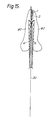
- Fig. 15 illustrates schematically the lowering of the hydrostatic sampler according to the present invention.
- Fig. 16 illustrates the sampler in fig. 15 ready for operation.
- Fig. 17 illustrates the sampler in fig. 16 during operation.
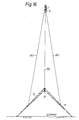
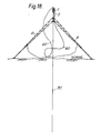
- Fig. 18 illustrates schematically the sampler in operation with full penetration of the sampler tube in the sedimentary layer.
- Fig. 1 shows schematically the general principle of the present invention and the basic connection of its main components.
- a hydraulic motor 2 is connected to the surrounding water masses over an intake valve 4 and a fluid filter 5.
- the hydrostatic pressure of the surrounding water masses leads water through the filter 5 and the valve 4 into the motor 2 which is adapted to converting the pressure energy of the through-flowing fluid into pressure energy which may be used by a work tool 1 connected with the motor 2.
- the spent working fluid of the motor i.e. the water now at a substantially lower pressure than the surrounding hydrostatic pressure, is conveyed to a low pressure reservoir 3.
- the low pressure reservoir 3 is essentially free of gases other than water vapour, such that the pressure in the low pressure reservoir is limited to the water vapour pressure throughout operating period of the motor 2, this operating period being determined by the cycle capacity of the motor 2 and the capacity of the low pressure reservoir.
- a certain amount of water at the surrounding hydrostatic pressure is depressurized and emptied to the low pressure reservoir.
- the operating cycles of the motor 2 continue until the low pressure reservoir is full of water.
- FIG. 2 A particular embodiment of the general principle of the invention is shown in Fig. 2, wherein the hydraulic motor 2a is provided in a low pressure chamber 11.
- the low pressure chamber 11 is rigidly connected with a high pressure cylinder 12 which forms part of the hydraulic motor 2a which further consists of a piston 15 and a piston rod 16.
- the high pressure cylinder 12 is divided in two cylinder volumes 120a and 120b on either side of piston 15.
- the cylinder volumes 120a and 120b are brought into alternating connection with the surrounding water masses via valves 13a and 13b and with the low pressure chamber 11 via valves 14a, 14b such that the hydraulic motor 2a now acts as a water-driven axial piston motor and a pulsating movement will be imparted to the piston 15 and the piston rod 16.
- the hydraulic piston motor 2a is connected with a piston pump 20 comprising a second piston 21 at the end of the piston rod 16 and provided in the second cylinder 22 which is rigidly connected with and has the same center axis as the first cylinder 12.
- a piston pump 20 comprising a second piston 21 at the end of the piston rod 16 and provided in the second cylinder 22 which is rigidly connected with and has the same center axis as the first cylinder 12.
- Separate cylinder volumes above and below the piston 21 is connected to the surroundings over two non-return valves depicted on the right hand of the cylinder 22 and with a second hydraulic motor 2b via two non-return valves depicted on the left side of the cylinder 22.
- the axial pump may now be used for driving the second hydraulic motor 2b which may be equipped with a work tool 1.
- the second hydraulic motor 2b may be of either the reciprocating or the rotary type, for instance a turbine.
- the second hydraulic motor 2b empties to an external low pressure reservoir 3b.
- the medium displaced by the axial pump 20 is the surrounding liquid and that the pump operates as an open system which "consumes" the surrounding liquid.
- the choke valve 18 and an accumulator 19 are provided between the valves 4 and 13a, 13b, in order to equalize the flow of the surrounding liquid through the filter 5.
- Fig. 4 shows a further embodiment of the invention with a separate, closed hydraulic system.
- the piston pump 20 and a hydraulic engine 31, preferably a rotary engine now together with the accumulators 32 and pressure control valves comprise a closed system which is operated by a separate hydraulic medium, for instance a suitable hydraulic oil, while only the hydraulic piston motor 2a still uses the surrounding water as its operating medium.
- the accumulators, one of which is indicated by 32 and the pressure regulating valves, one of which is indicated by 33 respectively are used for equalizing the supply pressure of the axial pump 20.
- the low pressure chamber 11 is connected with an accumulator 40 and an additional low pressure reservoir 3 via a pressure regulating valve 41.
- the additional low pressure reservoir 3 may be used for extending the operating period of the engine in Fig. 4 as the connection between the low pressure chamber 11 and the reservoir 3 may be engaged or disengaged according to need.
- the valve 41 controls the differential pressure between the chamber 11 and the reservoir 3, being a differential pressure limiting valve.
- Fig. 5 shows the hydrostatic engine according to the invention embodied as an impact device or percussion drill.
- the high pressure cylinder 12 is now arranged with its longitudinal axis approximately perpendicular to the seabed and the piston rod 16 is rigidly connected with an impact device with the same longitudinal axis as the piston rod 16.
- the lower chamber 120b in the high pressure cylinder 12 has a permanently open fluid connection with the low pressure chamber 11 and a constantly closed fluid connection with the external pressure, while only the upper chamber 120a in the high pressure cylinder 12 is adapted to provide an axial motor action.
- the valve 13a opens at a first stroke, while valve 14a is kept closed and hence the piston 15 is imparted a downwards directed movement and imparts a downwards directed impulse to the impact device 17.
- the cylinder 12 with the low pressure chamber 11 is given an upwards directed reaction movement.
- the valve 14a opens, while valve 13a is kept closed and the low pressure chamber 11 and the high pressure cylinder 12 are now imparted a dropping movement that ends with a second downwards directed impulse to the impact device 17, whereafter the first stroke once more is repeated.
- the cycles repeat until the low pressure reservoir 11, 3 is full or the intake valve 4 is closed.
- the impact device 17 may be a percussion drill, but a person skilled in the art will see that it is possible to convert the downwards directed pulsation or storke at least partially to a rotational movement via a per se known mechanical movement converter 170 attached to the drill stem. As shown in Fig.
- the axial pump 20 may be used for operating a hydraulic rotary motor 50 which imparts a rotational movement to the impact or percussion device 17.
- the impact device 17 may form the uppermost end of a sampler tube 60 consisting of one or more sampler tube sections which are adapted for taking samples of sediments in the seabed.
- a sampler tube 60 consisting of one or more sampler tube sections which are adapted for taking samples of sediments in the seabed.
- Fig. 7 shows a further embodiment of the hydrostatic machine according to the invention.
- the machine is used for driving an anchor 70 down into the sediments on the seabed.
- the impact device 17 forms the crown of an anchor 70 consisting of several arms 71 hinged near the crown 17 in order to offer as little resistance as possible when the anchor is driven into the seabed.
- the hinged arm 71 forms flukes when the anchor chain 72 is tensioned, as the arms 71 then unfolds.
- the anchor chain 72 is attached to the top of the low pressure chamber 11 and it is seen that the anchor device and the hydrostatic engine according to the invention forms an integral whole in which the machine's specific weight also makes a possible contribution to the effect of the anchor.
- FIG. 8 Another version of an anchor combine the hydrostatic machine according to invention is shown in Fig. 8.
- the machine is equipped with a screw 17 with large threads 171 which make it possible to firmly attach the screw to the seabed by imparting a rotary movement to the screw 17.
- the threads 171 are driven into the sediments with a combined hammering and screwing movement caused by the hydraulic axial piston pump 20 and a rotary hydraulic motor 75 respectively.
- the screw may hence be used for mooring or attaching the machine or any vessel attached to the machine via e.g. an anchor chain 72 fastened to the top of the low pressure chamber 11.
- the machine according to the invention may be used for moving a wheeled or caterpillared vehicle 100 on the sea bed, in which case the vehicle 100 may be thought of as the machine 1 according to the invention.
- a hydraulic motor 8 is connected either directly with hydraulic motor 2a or the axial pump 20.
- the hydraulic motor 80 is preferably a rotary engine used for imparting a rotary movement to rolling wheels or the driving wheels of a caterpillar and thus providing the necessary tractive force for the vehicle to move on the seabed.
- the hydraulic motor 80 will be equipped with suitable speed regulating means and allow for the steering and the speed of the vehicle to be controlled.
- Fig. 10 illustrates schematically the sampler according to the present invention.
- the hydrostatic sampler comprises a pressure reservoir 1 which forms the head of the sampler and which is composed of sections, thus enabling the volume of the pressure reservoir to be regulated according to the number of sections used in the embodiment.
- a high pressure cylinder 13 attached to the walls of the pressure reservoir.
- the high pressure cylinder has a high pressure chamber which via openings 133 and 134 is connected with a low pressure chamber 14 which is formed by the upper volume of the pressure reservoir 1, and via an inlet valve 11 in connection with the outside of the pressure reservoir.
- the high pressure chamber 130 constitutes the cylinder of a pump device which in reality is the sampler's motor, there being provided in the high pressure chamber 130 a first piston 131.
- This piston 131 is rigidly connected via the piston rod with a second piston 21 in a secondary pump system 2 which is fitted to an extension of the pressure reservoir 1.
- the object of the second piston 21 is first of all to cause the transfer of impact, or the lifting movement between the pressure reservoir 1 and a sampler section 3 which comprises the sampler tube 30, and secondly to provide a secondary pump system 2, in which the pump cylinder 2 can be emptied into the environment or used to inject water into the conduit 35 in order to provide lubrication of the sampler tube 30 via a three-way valve 22.
- a pressure relief valve 10 to the environment, while an equalization of pressure is obtained in the non-active cylinder volume in the secondary pump system 2, via opening 203 and three-way valve 22 respectively.
- the top plate of the pressure reservoir 1 is provided with an eye-bolt for the attachment of lines, while the pressure reservoir's top and bottom plates are attached by means of assembly bolts 7. The fitting of further sections to the pressure reservoir 1 can then be performed very easily by loosening the top or bottom plate of the pressure reservoir 1 and fitting the required number of extra sections, the length of the assembly bolts used naturally corresponding to the required length of the pressure reservoir 1.
- FIGS 11a and 11b illustrate in more detail a preferred embodiment of the hydrostatic sampler according to the invention.
- Fig. 11a illustrates a deep water version of the sampler, wherein the internal volume of the high pressure chamber 130 in the high pressure cylinder is reduced by the insertion of a lining 135, as is more clearly illustrated in fig. 12a.
- the ratio between the volume of the low pressure chamber 14 and the high pressure chamber 130 is thereby increased, thus enabling a correspondingly larger number of strokes to be achieved at great depth under a greater hydrostatic pressure, the number of impacts obviously being determined by the ratio between the chamber volumes.
- Fig. 11b illustrates a shallow water version of the hydrostatic sampler and, apart from the lining in the high pressure chamber 130, is exactly the same as the version in fig.
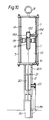
- the high pressure cylinder 13 is illustrated in more detail in figures 12a, 12b, 13a and 13b.
- a sleeve-shaped slide valve 15 which can be moved axially around the upper section of the high pressure cylinder.
- the valve housing 15 is provided with an inlet opening 150 which communicates with a corresponding inlet opening 133 in the high pressure cylinder 13 when the slide valve is located in an upper position on the high pressure cylinder, at the same time as the piston 131 in the high pressure cylinder is located in a starting position.
- the inlet opening 150 on the slide valve 15 is further connected with the inlet valve 11 via a flexible hose 12.
- the manoeuvering device 110 is triggered, the inlet valve 11 opened and water under the surrounding pressure streams through the flexible hose 12 and into the high pressure chamber 130, the piston 131 in the high pressure cylinder as shown in, e.g., fig.
- a first embodiment of the compression spring mechanism 16 is illustrated in fig. 12a, where the piston 131 is located in the starting position and in fig. 12b, where the piston is located in the final position.
- the compression spring mechanism here comprises a helical spring which is placed in a spring housing 162 and fitted around a spring bolt 161.
- the spring bolt 161 is passed through a fixed circumferential disc 151 on the slide valve 15 and a fixed locating disc 132 arranged on the piston rod at the bottom of the piston 131.
- the spring bolts are provided parallel to the piston and the spring housing 162 is installed in the high pressure cylinder 13 beside this, as illustrated in fig. 12a or fig. 12b.
- On the end of the spring bolts are fitted stop nuts 163 and 164.
- the slide valve In the starting position of the piston 131, the slide valve is kept pressed into its upper position by the compression spring 160 by means of the capture disc 132 which causes the spring housing to abut against the stop nut 164, thus causing the tension in the compression spring 160 to be completely relaxed and the upper stop nut 163 on the spring bolt 161 to abut against the circumferential disc 151 on the slide valve 15 and to draw this with it into a lower position, thus interrupting the communication between the inlet openings 133 and 150 and stopping the flow of water to the high pressure chamber 130.
- the piston 131 Under the weight of the pressure reservoir 1 or the sampler's head and if the pressure in the high pressure chamber 130 is equalized, the piston 131 now returns from the starting position to the final position, while at the same time the capture disc 132 once more abuts against the valve housing 160 and stretches the compression spring 160 which via the circumferential disc 151 again presses the slide valve into the upper position and creates a connection from the inlet valve 111 and through the openings 150 and 133 to the high pressure chamber which is filled once again, whereafter the piston stroke is repeated.
- the tension spring 170 which is considerably weaker than the compression spring 160 is again stretched during this operation, but naturally cannot counteract the return movement of the slide valve 15.
- the slide valve 15, together with the openings 133, 134 and 150 constitute a valve mechanism for the high pressure cylinder 130 which, together with the piston 131 in reality constitute a hydrostatic motor for the operation of the sampler.
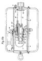
- Figures 13a and 13b illustrate a second embodiment of the spring mechanism for manoeuvering the slide valve 15, fig. 13a illustrating the piston 131 in the starting position and fig. 13b the piston in the final position.
- figs. 13a and 13b correspond to figures 11a and llb respectively and describe the same embodiment as illustrated there.
- a spring bolt 161 which is passed through an opening on the side of the high pressure cylinder, and through the circumferential disc 151 with which it is permanently connected.
- the capture disc 132 abuts against the stop nut 164 at the end of the rod and compresses the spring 160a against the circumferential disc 151 on the valve housing 15, which under the influence of the spring 160a is pressed against its lower position.
- the capture disc 132 also abuts against a stop nut 194 on the end of a camshaft 190, which similarly is arranged parallel to the first piston 131 on the outside of the high pressure cylinder 13 and passed through an opening on the side of this.
- a cam disc 191 On the camshaft 190 there is provided a cam disc 191, the camshaft and cam disc thus constituting a cam mechanism which can engage with cam groove 182 on a ratchet mechanism 18.
- the blocking mechanism 18 is located in the starting position of the slide valve 15 in blocking abutment against the circumferential disc 151, but the blocking is cancelled when the camshaft 190 is pulled with the capture disc 132, thus cancelling the engagement between the camshaft 191 and the cam groove 182 in the ratchet mechanism.
- the slide valve 15 thereby moves without hindrance under the influence of the compression spring 160a to the lower position, while a helical spring mechanism 17 which is attached to the upper section of the high pressure cylinder 13 and the camshaft, now that the cam disc is disengaged from the ratchet mechanism, pulls the camshaft 191 upwards, thus engaging the cam disc once again with the cam groove 182 in the ratchet mechanism 18, and the slide valve 15 via the circumferential disc engages in a locking manner with a locking groove 181 on the ratchet mechanism 18.
- the slide valve is thereby moved by the compression spring 160a and ends in its lower position, securely locked in this position by the ratchet mechanism 18, whereby free passage is created between the high pressure chamber 130 and the low pressure chamber 14 via the opening 134, thus equalizing the hydrostatic pressure, and the piston 131 begins the return stroke back to the starting position under the weight of the pressure reservoir or head 1 and the falling pressure in the high pressure chamber 130.
- the capture disc 132 pulls the sleeve 195 which is permanently fitted on to the camshaft 190 and also the sleeve 165 on to the spring bolt 161, during which the cam disc 191 is disengaged from the ratchet mechanism 18 and at the same time the compression spring 160b is stretched.
- the compression springs 160a and 160b are preferably designed as Belleville springs. As already described, the springs in the helical spring mechanism 17 are a tension spring 171.
- the first piston 131 as illustrated schematically in fig. 10 and in more detail in, e.g., fig. 12a, is rigidly connected via the piston rod with the second piston 21 in the secondary pump system 2, as is most clearly illustrated in figures 11a and llb. In fig. 11a both the pistons 131 and 21 are shown in their starting positions.
- the second piston 21 in the secondary pump cylinder 20 is moved to act upon the sampler tube which is connected to the lower end of the secondary pump piston 21 via the sampler tube adaptor 33.
- This can slide on the control bolt 24 which is attached in the locking ring 201 on the lower part of the secondary pump cylinder 20, and prevents the sampler tube 30 or the sampler tube adaptor 33 from rotating on the secondary pump piston 21.
- a three-way valve 22 which is opened during the lowering of the sampler and causes water to enter in under hydrostatic pressure into an annular space 202 which in the secondary pump piston's 21 starting position is created between the sliding bearing 200 on the secondary pump piston and the sliding bearing 211 on the inside of the wall of the secondary pump cylinder 20 when the sampler is positioned on the seabed, while at the same time it is opened for the working stroke of the piston 132.
- the secondary pump piston 21 is forced downwards, while at the same time the inlet opening in the three-way valve 22 is closed. In its place a connection is obtained between the annular space 202 and an outlet opening in the three-way valve which is connected with a flexible hose 23.
- the secondary pump pistor 21 returns to the starting position and the water is forced out via the opening 203 in the upper volume of the secondary pump cylinder 20, while the annular space 202 which is again formed during the return movement via the three-way valve 22 is connected with the environment and once again filled with water under hydrostatic pressure, after which the cycle is repeated.
- fig. 15 the sampler 1 is illustrated during lowering from, e.g., a research vessel.
- the head or pressure reservoir 1 is attached to the lowering line and on the sampler section 3 there is provided an attachment point for a support leg 6, which is shown closed around the sampler tube 30.
- Release lines 60 for the support legs are shown hanging in a slack arc around the sampler.
- the sampler according to the invention will be equipped with completely different instruments, including an inclination sensor for detecting the sampler's true inclination on the seabed, a sonar device for measuring the distance to the bottom, depths of penetration and also for the transfer of information on inclination.
- the sonar device which is not illustrated in more detail, but which may be, e.g., a known per se modulated pinger, indicates the distance to the bottom, thereby enabling the support legs 6 to be released and brought into position by the release line 60 before the sampler reaches the bottom, the support legs slidinc along the sampler tube to abut against the sampler head 31 as illustrated in fig. 16.
- any inclination indicated can now be compensated by means of the lines 60, thus allowing the sampler tube to be positioned in a substantially vertical manner.
- the driving operation continues in an alternating stroke cycle until the desired depth of penetration is achieved or the hydrostatic energy potential approaches zero. This usually involves approximately 200 strokes, depending, as mentioned above, on the ratio between the volume of the low pressure chamber and the volume of the high pressure chamber.
- the sampler and the sampler tube with the core sample are pulled up to the surface by means of a lifting line, the pressure in the high pressure chamber 130 and the low pressure chamber 14 now being the same and identical with the surrounding hydrostatic pressure.
- lifting the borehole is refilled with water to prevent the creation of a vacuum when the core sample and the sampler tube are pulled out.
- the pressure reservoir is decompressed via the pressure relief valve 10.
- the hydrostatic sampler weighs approximately 550 kg without the sampler tube. It is arranged to work at water depths between 200 and 6,000 m and consequently must be designed to resist the pressure forces which prevail at such depths. Depending on the water depth the number of strokes can be approximately 200 with an stroke length of approximately 350 mm. The possible penetration, depending on the nature of the sediments, can amount to up to 30 m, which means that the core sample's length is 30 m and this again means that special precautions must be taken on the mother vessel when the core sample is taken aboard.
- the stroke frequency used can vary from, e.g. 0.6 - 3 Hz, i.e. the actual sampling operation can be performed in the course of a few minutes or less.
- the stroke frequency can be adjusted via the inlet valve 111, and this is usually necessary as too high an stroke frequency results in severe dynamic loads on the piston rod. It will be obvious to those skilled in the art that there are a number of structural requirements which have to be satisfied in a hydrostatic sampler of this kind, with the purpose of operating at depths as low as 6,000 m. It is, e.g., important to dimension conduits and valves in order to avoid flow friction loss and there are naturally special requirements regarding resistance to corrosion, which can be met by the choice of the correct corrosion- and pressure-resistant materials.
- the operation of the sampler can be monitored by means of a hydrophone connected to an amplifier aboard the mother vessel in order to record the sound of the impacts.
- the sampler head 31 can be designed as a rotary drill chisel to which a rotating motion is provided by, e.g., converting a part of the impact energy to rotary motion by means of a suitable device, and in a known per se manner.
- the rotary movement could possibly also be provided directly by an additional hydrostatic motor.
- sampler tube itself, it is designed in a known per se manner and composed of sections which may, e.g., be 3 m in length.
- the individual sampler tube sections are connected by means of a tube section adaptor 36 which also provides fluid connection between the water injection conduits 35 inside the individual sections.
- a core retaining device 32 which grips the core and is pushed upwards in the tube sections during penetration.
Landscapes
- Engineering & Computer Science (AREA)
- Mining & Mineral Resources (AREA)
- Life Sciences & Earth Sciences (AREA)
- Geology (AREA)
- Geochemistry & Mineralogy (AREA)
- General Life Sciences & Earth Sciences (AREA)
- Fluid Mechanics (AREA)
- Physics & Mathematics (AREA)
- Environmental & Geological Engineering (AREA)
- Mechanical Engineering (AREA)
- Ocean & Marine Engineering (AREA)
- Sampling And Sample Adjustment (AREA)
- Earth Drilling (AREA)
- Investigation Of Foundation Soil And Reinforcement Of Foundation Soil By Compacting Or Drainage (AREA)
- Confectionery (AREA)
- Electrical Discharge Machining, Electrochemical Machining, And Combined Machining (AREA)
- Soil Working Implements (AREA)
- Control Of Velocity Or Acceleration (AREA)
Abstract
Description
Claims (30)
- A machine for performing work at great depths, consisting of at least one arbitrary work tool (1) of known per se type, at least one hydraulic motor (2) which is adapted in order to be able to be operated by the surrounding water masses, at least one low pressure reservoir (3), at least one intake valve (4) which is arranged so that the hydrostatic pressure in surrounding water masses leads water through the valve (4) via a pipe or hose connection to the motor (2) and further via a corresponding pipe or hose connection to the low pressure reservoir (3), and a per se known fluid filter (5) arranged in the surrounding water masses such that the fluid flow through the intake valve (4) to the motor (2) flows through the fluid filter (5), the motor (2) to the greatest possible extent by means of per se prior art converting the pressure energy in the through-flowing fluid into pressure energy which can be used by the work tool (1), characterized in that the at least one hydraulic motor (2) comprises a hydrostatic axial piston motor (2a) installed in communication with the low pressure reservoir (3) a low pressure chamber (11) thereof being rigidly connected with a high pressure cylinder (12) with at least two separate volumes (120a and 120b) forming an integral part of the axial piston motor (2a) and containing a piston (15) and piston rod (16) of the latter, that per se known valve devices (13a, 13b, 14a, 14b) bring one or more of the cylinder volumes (120a and 120b) into alternating communication with the surrounding water masses and the low pressure chamber (11) respectively in such a manner that the high pressure cylinder (12) acts as the working cylinder of a water-driven axial motor, imparting a pulsating or reciprocating movement to the piston (15) and the piston rod (16) provided in the high pressure cylinder (12).
- A machine according to claim 1, characterized in that between the valves (4) and (13a, 13b) there are provided a choke valve (18) and an accumulator (19) in order to equalize the fluid flow through the filter (5).
- A machine according to claim 1, characterized in that the low pressure reservoir (3) is approximately free of gases other than water vapour, the pressure in the low pressure reservoir being approximately limited to water vapour pressure at the relevant temperature throughout the entire work period from the time the reservoir is empty of water until it is completely full of water supplied from the environment.
- A machine according to claim 1, characterized in that the piston (15) and the piston rod (16) are rigidly connected with a second piston (21) provided in a second cylinder (22), that the second cylinder (22) is rigidly connected with and has the same centre axis as the first cylinder (12), and that the second cylinder (22) with the second piston (21) is equipped with per se known non-return valves, the second cylinder thus acting as an axial pump (20).
- A machine according to claim 4, characterized in that the medium pumped by the axial pump (20) is the surrounding liquid, and that the pump operates as an open system which "consumes" surrounding liquid.
- A machine according to claim 4, characterized in that the medium pumped by the axial pump (20) is a commercial hydraulic oil which is provided in a closed system comprising at a minimum the axial pump (20), a hydraulic motor (31) and related hose and valve connections.
- A machine according to claim 6, characterized in that the closed hydraulic system also comprises at least one accumulator (32) and at least one pressure regulating valve (33) for equalizing the supply pressure from the axial pump (20).
- A machine according to claim 1, characterized in that the low pressure chamber (11) is disengageably connected with an extra low pressure reservoir (3) via a hose or pipe connection, that the low pressure chamber (11) is directly connected with an accumulator (40), and that the differential pressure between the low pressure chamber (11) and the low pressure reservoir (3) is controlled by means of a differential pressure limiting valve (41)
- A machine according to claim 1, characterized in that the high pressure cylinder (12) is arranged with its longitudinal axis approximately perpendicular to the seabed, that the piston rod (16) is rigidly connected with an impact device (17) with approximately the same longitudinal axis as the piston rod (16), that the lower chamber (120b) has a constantly open fluid connection with the low pressure chamber (11) and constantly closed connection with the external pressure, while only the upper chamber (120a) is arranged so as to provide an axial motor effect, the valve (13a) being opened at the first stroke, while valve (14a) is kept closed, thus imparting to the piston (15) a downwards directed movement and causing a first downwards directed impulse to the impact device (17), the cylinder (12) with the low pressure chamber (11) being simultaneously given an upwards directed reaction movement, and that at the next stroke the valve (14a) is opened, while valve (13a) is kept closed, thus imparting to the low pressure chamber (11) and the high pressure cylinder (12) a dropping movement which ends with a second downwards directed impulse to the impact device (17) after which the first stroke is repeated, and so on until the differential pressure between the surrounding water and the low pressure chamber (11, 3) is insufficient, or the intake valve (4) is closed.
- A machine according to claim 9, characterized in that at least one motor (2) drives an electric generator.
- A machine according to claim 9, characterized in that the impact device (17) is in the form of a percussion drill and that the downwards directed pulsations are partially converted to rotational movement through a per se known mechanical device (170).
- A machine according to claims 4 and 9, characterized in that the impact device (17) is in the form of a percussion drill and that the axial pump (20) is used to operate a hydraulic rotary engine (50) which imparts a rotational movement to the impact device (17).
- A machine according to claims 9, 11 and 12, characterized in that the impact device (17) forms the top of a sampler tube (60) consisting of one or more sampler tube sections (61) arranged to take samples of sediments on the seabed.
- A machine according to claim 9, characterized in that the impact device (17) forms the bottom end of an anchor (70) which in known per se manner can consist of several arms (71) hinged near the bottom end (17) so that the anchor offers little resistance when driven into the seabed, but strong resistance when attempts are made to pull it up by means of, e.g., an anchor chain (72) attached to the top of the low pressure chamber (11), since the arms (71) are then unfolded.
- A machine according to claims 11 or 12, characterized in that the impact device (17) is in the form of a screw with relatively large threads (171), thus causing the screw to be attached to the bottom in such a manner that it anchors the machine and any vessel attached to it via, e.g., an anchor chain (72).
- A machine for performing work at great depths, consisting of at least one arbitrary work tool (1) of known per se type, at least one hydraulic motor (2) which is adapted in order to be able to be operated by the surrounding water masses, at least one low pressure reservoir (3), and at least one intake valve (4) which is arranged so that the hydrostatic pressure in surrounding water masses leads water through the valve (4) via a pipe or hose connection to the motor (2) and further via a corresponding pipe or hose connection to the low pressure reservoir (3), and a per se known fluid filter (5) arranged in the surrounding water masses such that the fluid flow through the intake valve (4) to the motor (2) flows through the fluid filter (5), the motor (2) to the greatest possible extent by means of per se prior art converting the pressure energy in the through-flowing fluid into pressure energy which can be used by the work tool (1), characterized in that the at least one hydraulic motor (2) is a rotary motor installed directly in the low pressure reservoir (3).
- A machine according to claim 16, characterized in that the at least one motor (2) drives an electrical generator.
- Use of the hydrostatic machine according to any of the claims 1-15 in a hydrostatic sampler especially for core samples of marine sediments, wherein the sampler consists of a cylindrical head (1) and a substantially cylindrical sampler section (3) whose longitudinal axis passes approximately through the head's (1) centre of gravity, and wherein the sampler section comprises a sampler tube (30) which consists of at least one sampler tube section, characterized in that the head (1) constitutes a pressure reservoir consisting of at least one reservoir section, that the pressure reservoir (1) comprises a low pressure chamber (14) and a working cylinder (13) with a high pressure chamber (130) provided in or directly connected with the low pressure chamber (14), that the high pressure chamber (130) is connected via an inlet opening (133) with the outside of the pressure reservoir and via a further opening (134) with the low pressure chamber (14), that in the high pressure chamber (130) there is provided a first piston (131), with direction of movement along the longitudinal axis of the sampler section (3), and that the sampler section (3) with the sampler tube (30) are arranged to perform a stroke movement generated by the effect of the hydrostatic pressure on the first piston (131), during which the said piston (131) moves from a starting position to a final position in the high pressure chamber (130) and thereafter due to the weight of the head (1) returns to the starting position during a downwards directed movement of the head (1) and the secondary pump cylinder (20) to abut against the sampler section (3).
- Use according to claim 18, characterized in that there is provided a secondary pump system (2) consisting of a secondary pump cylinder (20) with a second piston (21), the secondary pump cylinder (20) being rigidly connected with the head (1) and having the same central longitudinal axis as the head (1) and the sampler tube (30), and that the first piston (131) is rigidly connected with the second piston (21) and with the sampler section (3).
- Use according to claim 18 or 19, characterized in that the high pressure cylinder (13) on the outside of its upper section is surrounded by a sleeve-shaped slide valve (15) moveable in axial direction around this section, arranged to provide fluid communication between the high pressure chamber (130) and the environment respectively via the inlet opening (133) and between the high pressure chamber (130) and the low pressure chamber (14) via the additional opening (134), the additional opening (134) being composed of at least one outlet opening on the upper section of the first piston's (131) cylinder (13) in order to provide fluid communication between the high pressure chamber (13) and the low pressure chamber (14).
- Use according to claim 20, characterized in that the inlet opening (133) is in fluid communication with the high pressure chamber (130) via a first flexible hose (12) which is attached to an inlet opening (150) on the slide valve (15), the inlet opening (150) on the slide valve (15) being capable of fluid communication with at least one inlet opening (133) in the upper section of the cylinder (13).
- Use according to claim 20, characterized in that there are provided two sets of spring mechanisms (16) around one or more spring bolts (161) which are slidingly arranged parallel to the central longitudinal axis, that the first set of spring mechanisms (16) comprises springs which extend between a circumferential disc (151) on the slide valve (16) and a stop disk permanently connected to the spring bolts (161), that the second set of spring mechanisms (16) extends between the circumferential disc (151) and a locating disc (132) on the lower end of the first piston (131), and that the capture disc (132) abuts against a stop disk on the lower end of the spring bolts (161) when the first piston (131) approaches its lower end position, thus causing the first set of spring mechanisms to be tensioned, while the locating disc (132) tensions the second set of spring mechanisms when the first piston (131) approaches its upper position, the circumferential disc (151) and the slide valve (15) being affected by a spring load directed towards the same end position when the first piston (131) is located close to an end position.
- Use according to claim 20, characterized in that spring mechanisms (17) are provided around one or more camshafts (190) on both sides of a disk (136) which is permanently connected to the high pressure chamber (130), that the springs (170) in the spring mechanism (17) extend between the disc (136) and fixed points on the camshafts (190), that the camshafts (190) pass freely through the disc (136) and are axially slidingly arranged parallel to the central longitudinal axis, and that cam discs (191) are rigidly connected with the camshafts.
- Use according to claim 23, characterized in that there is provided a ratchet mechanism (18) which is arranged to lock the slide valve (15) axially when it is located in its upper or lower end position, that the ratchet mechanism (18) is spring loaded in the direction of the locking position and the cam discs (191), that the ratchet mechanism is located in the locking position when the cam discs (191) are located in a groove (182) in the ratchet mechanism, that this position of the cam discs (191) which corresponds to the groove (182) also corresponds to a neutral position of the spring mechanism (17) in relation to the camshafts' (190) axial movement, and that the ratchet mechanism (18) is forced away from the camshaft and out of the locking position when the cam disks (191) are forced downwards or upwards and out of the groove (182).
- Use according to claim 24, characterized in that the camshafts (190) pass through a capture disc (132) which is permanently connected with the lower end of the first piston (131), that when the piston approaches its lower end position, the capture disc (132) abuts against a disk, nut or the like which is rigidly connected with the lower end of the camshafts, and that when the first piston (131) approaches its upper final position, the capture disk abuts against a disk, sleeve (195), cross section extension or the like which is axially rigidly connected with the camshafts, so that close to an arbitrary final position the first piston forces the camshafts (190) with the cam disks (191) out of their neutral position and causes an opening of the ratchet mechanism (18).
- Use according to claim 18, characterized in that the volume of the first piston's (131) cylinder (13) is reduced by a lining (135) being provided in the high pressure chamber (130), the first piston being given a correspondingly reduced dimension.
- Use according to claim 18, characterized in that between the low pressure chamber (14) and the outside of the head (1) there is provided a one-way pressure relief valve (10), which opens from the chamber (14) to the outside of the head (1).
- Use according to claim 19, characterized in that the secondary pump cylinder (20) is provided with a three-way valve (22) on at least one end, the three-way valve (22) providing fluid communication between the outside of an annular space (202) which is created in the secondary pump cylinder on the side of the second piston (21) where the three-way valve (22) is provided, and that the three-way valve has an approximately direct connection with the outside when the second piston (21) causes a suction effect in the annular space (202), while the approximately direct connection is blocked at the same time as a connection is opened to a water injection conduit (35) via a second flexible hose (23) when the annular space (202) is compressed by the second piston (21), and that the water injection conduit (35) is provided in the sampler section (3) in order to provide fluid lubrication of the sampler tube (30) or water injection in the core hole when lifting the sampler tube (30).
- Use according to any of claims 18 to 28, characterized in that a valve (11) with a spring-loaded valve arm (110) closes the fluid connection between the high pressure chamber (130) and the environment when the valve arm (110) is located in its lower position when overcoming the spring moment which will tend to open the valve and move the valve arm (110) to its upper position, and that a weight is attached by a line to the outer end of the valve arm (110), the weight thus keeping the valve (11) closed until the weight hits the seabed when the sampler is being lowered, and the hydrostatic sampler will automatically begin to perform the impact movement when the distance between the seabed and the head (1) corresponds approximately to the length of the line between the valve arm (110) and the weight.
- Use according to any of the claims 18-29, characterized in that a high pressure hose connects the valve (11) directly or indirectly with a fluid compressor, thus enabling the supply of fluid from the said compressor to replace fluid from the environment under operating conditions where the hydrostatic pressure in the head's (1) environment is not sufficient to operate the sampler.
Applications Claiming Priority (5)
| Application Number | Priority Date | Filing Date | Title |
|---|---|---|---|
| NO911669A NO911669D0 (en) | 1991-04-26 | 1991-04-26 | MACHINE FOR PERFORMING WORK ON LARGE SEA DIP UNDER THE USE OF HYDROSTATIC PRESSURE. |
| NO911668A NO911668D0 (en) | 1991-04-26 | 1991-04-26 | HYDROSTATIC TESTAKER. |
| NO911668 | 1991-04-26 | ||
| NO911669 | 1991-04-26 | ||
| PCT/NO1992/000078 WO1992019836A1 (en) | 1991-04-26 | 1992-04-24 | Engine for performing subsea operations and devices driven by such an engine |
Publications (2)
| Publication Number | Publication Date |
|---|---|
| EP0581838A1 EP0581838A1 (en) | 1994-02-09 |
| EP0581838B1 true EP0581838B1 (en) | 1998-11-04 |
Family
ID=26648283
Family Applications (1)
| Application Number | Title | Priority Date | Filing Date |
|---|---|---|---|
| EP92909601A Expired - Lifetime EP0581838B1 (en) | 1991-04-26 | 1992-04-24 | Engine for performing subsea operations and use of it in a core sampler |
Country Status (8)
| Country | Link |
|---|---|
| EP (1) | EP0581838B1 (en) |
| JP (1) | JPH06506996A (en) |
| AT (1) | ATE173050T1 (en) |
| AU (1) | AU656186B2 (en) |
| CA (1) | CA2109107A1 (en) |
| DE (1) | DE69227511T2 (en) |
| NO (1) | NO933843L (en) |
| WO (1) | WO1992019836A1 (en) |
Families Citing this family (5)
| Publication number | Priority date | Publication date | Assignee | Title |
|---|---|---|---|---|
| NO964259D0 (en) * | 1996-10-07 | 1996-10-07 | Kaare Aardal | Hydrostatic work device and tools for the same |
| NO964723L (en) * | 1996-11-07 | 1998-05-08 | Selantic As | Inverted accumulator |
| CN102678682B (en) * | 2012-05-22 | 2015-06-10 | 淮海工学院 | Underwater constant pressure difference gas source |
| GB2573121B (en) | 2018-04-24 | 2020-09-30 | Subsea 7 Norway As | Injecting fluid into a hydrocarbon production line or processing system |
| CN110422306B (en) * | 2019-09-18 | 2024-05-03 | 江苏科技大学 | Seawater-driven deep-sea tracked vehicle chassis |
Family Cites Families (10)
| Publication number | Priority date | Publication date | Assignee | Title |
|---|---|---|---|---|
| US3118417A (en) * | 1962-07-30 | 1964-01-21 | Stanwick Tad | Method and apparatus for anchor embedment |
| US3418818A (en) * | 1966-04-22 | 1968-12-31 | Pan American Petroleum Corp | Underwater power source |
| US3436914A (en) * | 1967-05-29 | 1969-04-08 | Us Navy | Hydrostatic energy accumulator |
| US3412814A (en) * | 1967-06-28 | 1968-11-26 | Usa | Hydrostatic corer |
| US3504648A (en) * | 1968-04-29 | 1970-04-07 | Frederick A Kriedt | Deepwater hydraulic power unit |
| US3595012A (en) * | 1970-02-06 | 1971-07-27 | Us Navy | Sea pressure operated power device |
| US3670680A (en) * | 1970-09-25 | 1972-06-20 | Frederick A Kriedt | Water expulsion system |
| US4215544A (en) * | 1978-05-17 | 1980-08-05 | Tad Stanwick | Method of generating rotary power in a deepsea environment |
| US4619593A (en) * | 1979-09-11 | 1986-10-28 | Steven Molnar | Apparatus comprising a turbine and associated water extractor and method of translating the potential energy of deep sea water into useful work |
| NL8800632A (en) * | 1988-03-15 | 1989-10-02 | Ihc Holland Nv | METHOD FOR DRIVING A HYDRAULIC UNDERWATER TOOL. |
-
1992
- 1992-04-24 WO PCT/NO1992/000078 patent/WO1992019836A1/en not_active Ceased
- 1992-04-24 EP EP92909601A patent/EP0581838B1/en not_active Expired - Lifetime
- 1992-04-24 AT AT92909601T patent/ATE173050T1/en not_active IP Right Cessation
- 1992-04-24 JP JP4509027A patent/JPH06506996A/en active Pending
- 1992-04-24 DE DE69227511T patent/DE69227511T2/en not_active Expired - Fee Related
- 1992-04-24 CA CA002109107A patent/CA2109107A1/en not_active Abandoned
- 1992-04-24 AU AU16869/92A patent/AU656186B2/en not_active Ceased
-
1993
- 1993-10-25 NO NO933843A patent/NO933843L/en unknown
Also Published As
| Publication number | Publication date |
|---|---|
| AU1686992A (en) | 1992-12-21 |
| ATE173050T1 (en) | 1998-11-15 |
| WO1992019836A1 (en) | 1992-11-12 |
| EP0581838A1 (en) | 1994-02-09 |
| NO933843L (en) | 1993-12-27 |
| NO933843D0 (en) | 1993-10-25 |
| JPH06506996A (en) | 1994-08-04 |
| DE69227511D1 (en) | 1998-12-10 |
| DE69227511T2 (en) | 1999-07-15 |
| AU656186B2 (en) | 1995-01-27 |
| CA2109107A1 (en) | 1992-10-27 |
Similar Documents
| Publication | Publication Date | Title |
|---|---|---|
| US2176477A (en) | Method of and apparatus for taking earth cores | |
| US8668472B2 (en) | Wave actuated pump and means of connecting same to the seabed | |
| US6647716B2 (en) | Ocean wave power generator (a “modular power-producing network”) | |
| US3718316A (en) | Hydraulic-pneumatic weight control and compensating apparatus | |
| US4934870A (en) | Production platform using a damper-tensioner | |
| US20090165455A1 (en) | Methods and apparatus for energy production | |
| CN107255060A (en) | Rope draining cylinder pressure wave-activated generator | |
| MX2011000838A (en) | System and method for driving pile under water. | |
| CN103587653B (en) | Oceanographic observation subsurface buoy | |
| US5382760A (en) | Seismic well source | |
| US3824797A (en) | Evacuated tube water hammer pile driving | |
| US3259371A (en) | Wave cancellation system for a floating drilling vessel | |
| AU656186B2 (en) | Engine for performing subsea operations and devices driven by such an engine | |
| US8496410B2 (en) | Method and apparatus for penetrating particulate substrates | |
| US2967400A (en) | Method and apparatus for erecting offshore platform | |
| US5456325A (en) | Method and apparatus for driving a probe into the earth | |
| US4234046A (en) | Pressure differential seafloor corer-carrier | |
| US3418818A (en) | Underwater power source | |
| Wang et al. | Energy performance evaluation of an innovative hydrostatic motor | |
| US20080292407A1 (en) | System and Method for Installing Foundation Elements | |
| SU1448022A1 (en) | Underwater drilling rig | |
| US3371643A (en) | Hydraulically actuated driver | |
| CN224051626U (en) | Submarine sampling equipment | |
| Chen et al. | Development and Sea Trials of a Deep-sea Energy Storage Buoyancy Regulating System | |
| WO1998020257A1 (en) | Inverted accumulator |
Legal Events
| Date | Code | Title | Description |
|---|---|---|---|
| PUAI | Public reference made under article 153(3) epc to a published international application that has entered the european phase |
Free format text: ORIGINAL CODE: 0009012 |
|
| 17P | Request for examination filed |
Effective date: 19931124 |
|
| AK | Designated contracting states |
Kind code of ref document: A1 Designated state(s): AT BE CH DE DK ES FR GB GR IT LI LU MC NL SE |
|
| 17Q | First examination report despatched |
Effective date: 19950308 |
|
| GRAG | Despatch of communication of intention to grant |
Free format text: ORIGINAL CODE: EPIDOS AGRA |
|
| GRAG | Despatch of communication of intention to grant |
Free format text: ORIGINAL CODE: EPIDOS AGRA |
|
| GRAH | Despatch of communication of intention to grant a patent |
Free format text: ORIGINAL CODE: EPIDOS IGRA |
|
| GRAH | Despatch of communication of intention to grant a patent |
Free format text: ORIGINAL CODE: EPIDOS IGRA |
|
| GRAA | (expected) grant |
Free format text: ORIGINAL CODE: 0009210 |
|
| AK | Designated contracting states |
Kind code of ref document: B1 Designated state(s): AT BE CH DE DK ES FR GB GR IT LI LU MC NL SE |
|
| PG25 | Lapsed in a contracting state [announced via postgrant information from national office to epo] |
Ref country code: SE Free format text: THE PATENT HAS BEEN ANNULLED BY A DECISION OF A NATIONAL AUTHORITY Effective date: 19981104 Ref country code: LI Free format text: LAPSE BECAUSE OF FAILURE TO SUBMIT A TRANSLATION OF THE DESCRIPTION OR TO PAY THE FEE WITHIN THE PRESCRIBED TIME-LIMIT Effective date: 19981104 Ref country code: IT Free format text: LAPSE BECAUSE OF FAILURE TO SUBMIT A TRANSLATION OF THE DESCRIPTION OR TO PAY THE FEE WITHIN THE PRE;WARNING: LAPSES OF ITALIAN PATENTS WITH EFFECTIVE DATE BEFORE 2007 MAY HAVE OCCURRED AT ANY TIME BEFORE 2007. THE CORRECT EFFECTIVE DATE MAY BE DIFFERENT FROM THE ONE RECORDED.SCRIBED TIME-LIMIT Effective date: 19981104 Ref country code: GR Free format text: LAPSE BECAUSE OF NON-PAYMENT OF DUE FEES Effective date: 19981104 Ref country code: FR Free format text: LAPSE BECAUSE OF FAILURE TO SUBMIT A TRANSLATION OF THE DESCRIPTION OR TO PAY THE FEE WITHIN THE PRESCRIBED TIME-LIMIT Effective date: 19981104 Ref country code: ES Free format text: THE PATENT HAS BEEN ANNULLED BY A DECISION OF A NATIONAL AUTHORITY Effective date: 19981104 Ref country code: CH Free format text: LAPSE BECAUSE OF FAILURE TO SUBMIT A TRANSLATION OF THE DESCRIPTION OR TO PAY THE FEE WITHIN THE PRESCRIBED TIME-LIMIT Effective date: 19981104 Ref country code: BE Free format text: LAPSE BECAUSE OF FAILURE TO SUBMIT A TRANSLATION OF THE DESCRIPTION OR TO PAY THE FEE WITHIN THE PRESCRIBED TIME-LIMIT Effective date: 19981104 Ref country code: AT Free format text: LAPSE BECAUSE OF FAILURE TO SUBMIT A TRANSLATION OF THE DESCRIPTION OR TO PAY THE FEE WITHIN THE PRESCRIBED TIME-LIMIT Effective date: 19981104 |
|
| REF | Corresponds to: |
Ref document number: 173050 Country of ref document: AT Date of ref document: 19981115 Kind code of ref document: T |
|
| REG | Reference to a national code |
Ref country code: CH Ref legal event code: EP |
|
| REF | Corresponds to: |
Ref document number: 69227511 Country of ref document: DE Date of ref document: 19981210 |
|
| PG25 | Lapsed in a contracting state [announced via postgrant information from national office to epo] |
Ref country code: DK Free format text: LAPSE BECAUSE OF FAILURE TO SUBMIT A TRANSLATION OF THE DESCRIPTION OR TO PAY THE FEE WITHIN THE PRESCRIBED TIME-LIMIT Effective date: 19990204 |
|
| EN | Fr: translation not filed | ||
| PG25 | Lapsed in a contracting state [announced via postgrant information from national office to epo] |
Ref country code: LU Free format text: LAPSE BECAUSE OF NON-PAYMENT OF DUE FEES Effective date: 19990424 Ref country code: GB Free format text: LAPSE BECAUSE OF NON-PAYMENT OF DUE FEES Effective date: 19990424 |
|
| REG | Reference to a national code |
Ref country code: CH Ref legal event code: PL |
|
| PGFP | Annual fee paid to national office [announced via postgrant information from national office to epo] |
Ref country code: DE Payment date: 19990622 Year of fee payment: 8 |
|
| PLBE | No opposition filed within time limit |
Free format text: ORIGINAL CODE: 0009261 |
|
| 26N | No opposition filed | ||
| PG25 | Lapsed in a contracting state [announced via postgrant information from national office to epo] |
Ref country code: MC Free format text: LAPSE BECAUSE OF NON-PAYMENT OF DUE FEES Effective date: 19991031 |
|
| PG25 | Lapsed in a contracting state [announced via postgrant information from national office to epo] |
Ref country code: NL Free format text: LAPSE BECAUSE OF NON-PAYMENT OF DUE FEES Effective date: 19991101 |
|
| GBPC | Gb: european patent ceased through non-payment of renewal fee |
Effective date: 19990424 |
|
| NLV4 | Nl: lapsed or anulled due to non-payment of the annual fee |
Effective date: 19991101 |
|
| PG25 | Lapsed in a contracting state [announced via postgrant information from national office to epo] |
Ref country code: DE Free format text: LAPSE BECAUSE OF NON-PAYMENT OF DUE FEES Effective date: 20010201 |