EP0580942A1 - Light output body for fiber-optic light guides - Google Patents
Light output body for fiber-optic light guides Download PDFInfo
- Publication number
- EP0580942A1 EP0580942A1 EP93103819A EP93103819A EP0580942A1 EP 0580942 A1 EP0580942 A1 EP 0580942A1 EP 93103819 A EP93103819 A EP 93103819A EP 93103819 A EP93103819 A EP 93103819A EP 0580942 A1 EP0580942 A1 EP 0580942A1
- Authority
- EP
- European Patent Office
- Prior art keywords
- light
- light exit
- emitting
- body according
- exit
- Prior art date
- Legal status (The legal status is an assumption and is not a legal conclusion. Google has not performed a legal analysis and makes no representation as to the accuracy of the status listed.)
- Granted
Links
Images


Classifications
-
- G—PHYSICS
- G02—OPTICS
- G02B—OPTICAL ELEMENTS, SYSTEMS OR APPARATUS
- G02B5/00—Optical elements other than lenses
-
- G—PHYSICS
- G02—OPTICS
- G02B—OPTICAL ELEMENTS, SYSTEMS OR APPARATUS
- G02B6/00—Light guides; Structural details of arrangements comprising light guides and other optical elements, e.g. couplings
- G02B6/0001—Light guides; Structural details of arrangements comprising light guides and other optical elements, e.g. couplings specially adapted for lighting devices or systems
- G02B6/0005—Light guides; Structural details of arrangements comprising light guides and other optical elements, e.g. couplings specially adapted for lighting devices or systems the light guides being of the fibre type
- G02B6/0008—Light guides; Structural details of arrangements comprising light guides and other optical elements, e.g. couplings specially adapted for lighting devices or systems the light guides being of the fibre type the light being emitted at the end of the fibre
-
- G—PHYSICS
- G02—OPTICS
- G02B—OPTICAL ELEMENTS, SYSTEMS OR APPARATUS
- G02B6/00—Light guides; Structural details of arrangements comprising light guides and other optical elements, e.g. couplings
- G02B6/24—Coupling light guides
- G02B6/26—Optical coupling means
- G02B6/262—Optical details of coupling light into, or out of, or between fibre ends, e.g. special fibre end shapes or associated optical elements
-
- G—PHYSICS
- G09—EDUCATION; CRYPTOGRAPHY; DISPLAY; ADVERTISING; SEALS
- G09F—DISPLAYING; ADVERTISING; SIGNS; LABELS OR NAME-PLATES; SEALS
- G09F13/00—Illuminated signs; Luminous advertising
- G09F13/04—Signs, boards or panels, illuminated from behind the insignia
- G09F13/0418—Constructional details
- G09F13/0472—Traffic signs
-
- G—PHYSICS
- G09—EDUCATION; CRYPTOGRAPHY; DISPLAY; ADVERTISING; SEALS
- G09F—DISPLAYING; ADVERTISING; SIGNS; LABELS OR NAME-PLATES; SEALS
- G09F9/00—Indicating arrangements for variable information in which the information is built-up on a support by selection or combination of individual elements
- G09F9/30—Indicating arrangements for variable information in which the information is built-up on a support by selection or combination of individual elements in which the desired character or characters are formed by combining individual elements
- G09F9/305—Indicating arrangements for variable information in which the information is built-up on a support by selection or combination of individual elements in which the desired character or characters are formed by combining individual elements being the ends of optical fibres
- G09F2009/3055—Indicating arrangements for variable information in which the information is built-up on a support by selection or combination of individual elements in which the desired character or characters are formed by combining individual elements being the ends of optical fibres for traffic signs
Abstract
Description
Die Erfindung betrifft einen Lichtaustrittskörper für faseroptische Lichtleiter, insbesondere für Signalanzeigevorrichtungen zum Anzeigen von Verkehrszeichen, weicher zum Ausstrahlen des einem Rasterpunkt in der Anzeigefläche über Lichtleiter zugeführten Lichts ein Lichteintrittsende zum Verbinden mit dem zuführenden Ende des zugeordneten Lichtleiters und ein Lichtaustrittsende, welches in der Anzeigefläche die Lichtaustrittsfläche des Rasterpunktes bildet, aufweist sowie einen lichtleitenden Mittelbereich zwischen Lichteintritts- und Lichtaustrittsende, der sich zum Lichtaustrittsende hin im wesentlichen konisch oder pyramidal aufweitet.The invention relates to a light exit body for fiber optic light guides, in particular for signal display devices for displaying traffic signs, softer for emitting the light supplied to a raster point in the display area via light guides, a light entry end for connecting to the supplying end of the assigned light guide and a light exit end which is located in the display area Forms light exit surface of the raster point, and also has a light-guiding central region between the light entry end and the light exit end, which widens essentially conically or pyramidally towards the light exit end.
Solche Lichtaustrittskörper sind z.B. aus der DE 24 37 580 C2 bekannt. Die DE 24 37 580 C2 beschreibt faseroptische Signalanzeigevorrichtungen zum Ausstrahlung von Lichtzeichen, insbesondere Verkehrszeichen, bei welchen sich das darzustellende Symbol aus einer Vielzahl von Lichtpunkten in der Rasterplatte einer Anzeigefläche zusammensetzt. Die Beleuchtung der Lichtpunkte erfolgt mittels eines oder mehrerer mehrarmiger Lichtleiter, welche an ihrem einen Ende für die gleichzeitige und gemeinsame Beleuchtung mittels einer Lichtquelle bündelartig zusammengefaßt sind und an ihrem anderen Ende in die entsprechenden Öffnungen der Rasterplatte münden. In diesen Öffnungen befinden sich nach der Druckschrift die Lichtaustrittskörper, die aus einem optisch transparenten Material bestehen und im wesentlichen die Gestalt von Kegelstümpfen aufweisen. Sie sind in den Öffnungen so angeordnet, daß ihre Grundflächen die Lichtaustrittsflächen der Rasterpunkte in der Anzeigefläche bilden, ihre Schnittflächen dagegen auf der Rückseite der Rasterplatte zur optischen Ankopplung an die jeweils zugeordneten Lichtleiter dienen.Such light exit bodies are known for example from DE 24 37 580 C2. DE 24 37 580 C2 describes fiber-optic signal display devices for emitting light signs, in particular traffic signs, in which the symbol to be displayed is composed of a large number of light points in the grid plate of a display surface. The light points are illuminated by means of one or more multi-arm light guides which are bundled together at one end for simultaneous and common illumination by means of a light source and open at the other end into the corresponding openings in the grid plate. According to the publication, the light exit bodies, which consist of an optically transparent material and essentially have the shape of truncated cones, are located in these openings. They are arranged in the openings in such a way that their base areas form the light exit areas of the grid points in the display area, their cut areas on the other hand Back of the grid plate for optical coupling to the respective assigned light guide.
Die Verwendung im wesentlichen kegelstumpfförmiger Lichtaustrittskörper hat nach der Druckschrift den Vorteil, daß die Abstrahlcharakteristik des Lichtes aus den einzelnen Rasterpunkten dahingehend verbessert wird, daß das abgestrahite Licht nicht nur stärker gebündelt und damit in Richtung auf den Betrachter eine größere Leuchtdichte erzielt wird; darüber hinaus wird auch noch der Durchmesser eines einzelnen Rasterpunktes im Vergleich zum Durchmesser des ihn versorgenden Lichtleiters vergrößert, so daß er für den Betrachter besser wahrnehmbar ist Hieraus resultieren nach der Druckschrift eine starke Leuchtkraft und eine hohe Konturenschärfe der ausgestrahlten Lichtsignale, was insbesondere auch bei schlechten Wetterverhältnissen zu einer noch guten Sichtbarkeit der Zeichen führen soll.The use of a substantially frustoconical light-emitting body has the advantage, according to the publication, that the radiation characteristic of the light from the individual raster points is improved in such a way that the emitted light is not only bundled more strongly and thus a greater luminance is achieved in the direction of the viewer; In addition, the diameter of a single raster point is also enlarged in comparison to the diameter of the light guide supplying it, so that it is more perceptible to the viewer. According to the publication, this results in a strong luminosity and high sharpness of the contours of the emitted light signals, which is particularly true for poor ones Weather conditions should lead to a still good visibility of the signs.
Die Abstrahlcharakteristik des bekannten Lichtleitkörpers wird im wesentlichen durch die Geometrie, d.h. die Abmessungen des Kegelstumpfes bestimmt. Auf jeden Fall ist der Abstrahlkegel aber kein scharf begrenztes Gebilde, sondern hat zum Rand hin einen relativ weichen Übergang. Die in kartesischen Koordinaten aufgetragene Winkelverteilung der Energie ähnelt eher einer Gauß'schen Kurve als einer Rechteckfunktion.The radiation characteristic of the known light guide body is essentially determined by the geometry, i.e. determines the dimensions of the truncated cone. In any case, the radiation cone is not a sharply defined structure, but has a relatively smooth transition towards the edge. The angular distribution of the energy plotted in Cartesian coordinates resembles a Gaussian curve rather than a rectangular function.
Beim Aufstellen der bekannten Signalsysteme auf mehrspurigen Autobahnen sowie bei Installation seitlich der Straße ist es wünschenswert, daß der Abstrahlwinkel breiter ist, als dies für reine Spursignalisation auf Autobahnen erforderlich ist. Der Nachteil bei den beschriebenen Systemen ist jedoch, daß mit dem größeren Abstrahlwinkel die Achslichtstärke überproportional abnimmt. So sinkt zum Beispiel bei einer Aufweitung des Abstrahlwinkels von 6° auf 12° die Achslichtstärke auf 25% ihres ursprünglichen Wertes.When setting up the known signal systems on multi-lane motorways and when installing on the side of the road, it is desirable that the radiation angle is wider than is necessary for pure lane signaling on motorways. The disadvantage of the systems described, however, is that the axis light intensity decreases disproportionately with the larger radiation angle. For example, if the beam angle is expanded from 6 ° to 12 °, the axis light intensity drops to 25% of its original value.
Die Aufgabe der Erfindung ist, einen Lichtaustrittskörper der eingangs beschriebenen Art unter Beibehaltung seiner bekannten Vorteile so weiterzubilden, daß eine Vergrößerung des Abstrahlwinkels bei gleichmäßiger hoher Lichtstärke über den gesamten Winkelbereich erreicht wird.The object of the invention is to develop a light-emitting body of the type described in the introduction while maintaining its known advantages in such a way that the beam angle is increased with uniformly high light intensity over the entire angular range.
Diese Aufgabe wird durch einen Lichtaustrittskörper mit den Merkmalen des Patentanspruchs 1 gelöst.This object is achieved by a light exit body with the features of
Es hat sich in überraschender Weise gezeigt, daß durch einen sich verjüngenden Verlängerungsabschnitt am Austrittsende des bekannten Lichtaustrittskörpers nicht nur die erwünschte Verbreitetung des Abstrahlwinkels erzielt wird, sondern auch eine über den gesamten wirksamen Winkelbereich gleichmäßige, hohe Lichtstärke mit einem steilen Abfall der Lichtstärke zu größeren Winkeln hin. Dieses Ergebnis ist insbesondere deshalb unerwartet, da sich nach außen hin verjüngende Austrittsenden bei Lichtleitern üblicherweise dann eingesetzt werden, wenn eine Fokussierung des ausgestrahlten Lichts im Nahbereich erreicht werden soll, was zwangsläufig zu einer Divergenz der Lichtstrahlen im Fernbereich führt.It has surprisingly been found that a tapered extension section at the exit end of the known light-emitting body not only achieves the desired spread of the radiation angle, but also a high luminous intensity that is uniform over the entire effective angular range, with a steep drop in luminous intensity to larger angles there. This result is particularly unexpected, since outwardly tapering exit ends are typically used in light guides when the emitted light is to be focused in the close range, which inevitably leads to a divergence of the light beams in the far range.
Der mittlere Bereich des Lichtaustrittskörpers, in welchem das Licht vom Eintritts- zum Austrittsende geführt wird, erweitert sich im wesentlichen konisch oder pyramidal zum Austrittsende hin. Dies bedeutet, daß nicht nur die bevorzugte Kegelstumpfgestalt des Mittelbereiches zu der erfindungsgemäßen Wirkung führt, sondern auch andere geometrische Formen, die der Kegelstumpfgestalt nahe kommen, wie z.B. ein Pyramidenstumpf mit regelmäßigem oder unregelmäßigem Vieleck als Grundfläche, ein Kegelstumpf mit runder Schnittfläche, aber mit einer Grundfläche mit beliebiger Gestalt, z-B. zur Erzielung einer gewünschten Asymmetrie in der Winkelverteilung der Strahlung, u.a. Letzteres kann wünschenswert sein, wenn man eine Winkelverteilung des abgestrahlten Lichts erzielen will, die nicht rotationssymmetrisch ist Dies kann zum Beispiel der Fall sein, wenn bei einer erfindungsgemäßen Signalanzeigevorrichtung der Abstrahlwinkel in horizontaler Richtung verhältnismäßig breit, in vertikaler Richtung aber auf die Augenhöhe eines Beobachters beschränkt bleiben soll, wodurch Lichtverluste nach oben und unten vermieden werden sollen. In einem solchen Fall muß die Querschnittsfläche am Lichtaustrittsende des mittleren Bereiches in vertikaler Richtung einen größeren Durchmesser aufweisen als in horizontaler Richtung. Die geometrische Form kann hierbei im einzelnen ganz den Erfordernissen angepaßt werden, wie z.B. der Aufteilung der Rasterplatte für die Signalanzeige. Die Gestalt der Grundfläche des sich anschließenden Verlängerungsabschnitts ist entsprechend anzupassen.The central area of the light exit body, in which the light is guided from the entry end to the exit end, widens essentially conically or pyramidally towards the exit end. This means that not only the preferred truncated cone shape of the central region leads to the effect according to the invention, but also other geometric shapes that come close to the truncated cone shape, such as a truncated pyramid with a regular or irregular polygon as the base, a truncated cone with a round cut surface, but with one Base area with any shape, e.g. to achieve a desired asymmetry in the angular distribution of the radiation, inter alia the latter may be desirable if one wants to achieve an angular distribution of the emitted light that is not rotationally symmetrical. This may be the case, for example, when the radiation angle in the horizontal direction is proportional in a signal display device according to the invention wide, but should be limited to the eye level of an observer in the vertical direction, thereby avoiding light losses up and down. In such a case, the cross-sectional area at the light exit end of the central region must have a larger diameter in the vertical direction than in the horizontal direction. The geometric shape can be adapted to individual requirements, such as the division of the grid plate for signal display. The shape of the base of the adjoining extension section must be adapted accordingly.
Des weiteren sollen durch den Begriff "im wesentlichen" auch solche Körper in die Erfindung einbezogen sein, deren Gestalt fertigungstechnisch bedingt von der mathematisch exakten Kegel- oder Pyramidenstumpfgestalt geringfügig abweicht.Furthermore, the term "essentially" should also include those bodies in the invention whose shape differs slightly from the mathematically exact shape of a truncated cone or truncated pyramid due to manufacturing technology.
Keinesfalls in die Erfindung einbezogen sind Körper, wie sie aus der DE-OS 2 240 780 bekannt sind. Die DE-OS 2 240 780 betrifft eine Lichtausrittszelle für optische Faserlichtleiter, die aus einem massiven, aus optisch durchlässigem Material hergestellten Rotationsparaboloid besteht, in dessen Brennpunkt die Enden der ankommenden Faserlichtleiter befestigt, z.B eingegossen sind und dessen Oberfläche als Totalreflektor wirkt. Bei einer solchen Ausbildung ergibt sich eine ungünstige Leuchtdichtenverteilung, da in der Nähe der optischen Achse eine unerwünschte Leuchtdichtenspitze auftritt, die man, wie aus den Figuren 2 und 3 der Druckschrift hervorgeht, durch eine Streuscheibe oder Linse abzubauen versucht. Dieser Nachteil läßt sich auch nicht durch einen sich nach außen hin verjüngenden Verlängerungsabschnitt am Austrittsende der Lichtaustrittszelle übewinden.Bodies as are known from DE-OS 2 240 780 are in no way included in the invention. DE-OS 2 240 780 relates to a light exit cell for optical fiber light guides, which consists of a solid, paraboloid of revolution made of optically transparent material, in the focal point of which the ends of the incoming fiber light guides are fastened, e.g. cast in, and the surface of which acts as a total reflector. Such a configuration results in an unfavorable luminance distribution, since an undesired peak of luminance occurs in the vicinity of the optical axis, which, as can be seen from FIGS. 2 and 3 of the document, is attempted to be reduced by a diffusing screen or lens. This disadvantage cannot be overcome by an extension section tapering towards the outside at the exit end of the light exit cell.
Die beste Abstrahlcharakteristik im obigen Sinne erhält man mit einem erfindungsgemäßen Lichtaustrittskörper, der einen kegelstumpfförmigen Mittelbereich aufweist, an den sich ein sich konisch verjüngender Verlängerungsabschnitt anschließt. Daneben sind aber auch Ausführungsformen denkbar, bei welchen der Verlängerungsabschnitt eine Pyramide, ein Kegel- oder Pyramidenstumpf oder ein ähnliches Gebilde darstellt. Überraschenderweise läßt sich die erfindungsgemäße Wirkung nicht mit einem Verlängerungsabschnitt erzielen, der die Gestalt eine plankonvexen Linse, wie sie in Figur 3 der DE-OS 2 240 780 dargestellt ist, hat.The best radiation characteristic in the above sense is obtained with a light exit body according to the invention which has a frustoconical central region, which is adjoined by a conically tapered extension section. In addition, embodiments are also conceivable in which the extension section represents a pyramid, a truncated cone or truncated pyramid or a similar structure. Surprisingly, the effect according to the invention cannot be achieved with an extension section which has the shape of a plano-convex lens as shown in FIG. 3 of DE-OS 2 240 780.
Der Lichtaustrittskörper nach der Erfindung besteht aus einem optisch transparenten Material, wie z.B. Glas oder Kunststoff. Bevorzugt besteht er aus einem Kunststoff und wird einstückig in einem Spritzgußverfahren hergestellt.The light exit body according to the invention consists of an optically transparent material, such as glass or plastic. It preferably consists of a plastic and is produced in one piece in an injection molding process.
Nachfolgend wird die Erfindung anhand der Figuren und eines Ausführungsbeispiels näher erläutert:The invention is explained in more detail below with reference to the figures and an exemplary embodiment:
Es zeigen:
Figur 1- in einer schematischen Längsschnittdarstellung einen aus dem Stand der Technik bekannten, als Kegelstumpf ausgebildeten Lichtaustrittskörper mit planer Lichtaustrittsfläche
Figur 2- in der gleichen Darstellungsweise einen erfindungsgemäßen Lichtaustrittskörper nach einer bevorzugten Ausführungsform mit einem kegeistumpfförmigen Mittelbereich und einem konusförmigen Verlängerungsabschnitt
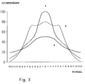
Figur 3- zur Verdeutlichung der Verbesserung der Abstrahlcharakteristik durch die Erfindung ein Diagramm, in weichem für einen bekannten und einen erfindungsgemäßen Lichtaustrittskörper die Lichtstärkeverteilung über dem Abstrahlwinkel aufgetragen ist.
- Figure 1
- in a schematic longitudinal sectional view of a known from the prior art, designed as a truncated cone light outlet body with a flat light outlet surface
- Figure 2
- in the same representation, a light exit body according to the invention according to a preferred embodiment with a truncated cone-shaped central region and a conical extension section
- Figure 3
- To illustrate the improvement of the radiation characteristic by the invention, a diagram in which the luminous intensity distribution is plotted against the radiation angle for a known and a light exit body according to the invention.
In Figur 1 ist ein bekannter, als Kegelstumpf ausgebildeter Lichtaustrittskörper (1) zu sehen. Der Lichtaustrittskörper besteht aus einem optisch transparenten Material, beispielsweise aus Glas oder Kunststoff und besitzt eine Brechzahl n₁, die größer sein muß, als die Brechzahl no des umgebenden Mediums, um eine Totalreflexion der von innen auf die Mantelfläche (2) des Kegelstumpfes auftreffenden Lichtstrahlen zu bewirken. Man erkennt in Figur 1 Lichtstrahlen (3) und (4), die z.B. aus einem Lichtleiter unter Winkeln α₃ und α₄ zur Flächennormalen auf die Schnittfläche (5) des Kegelstumpfes auftreffen. Der Lichtstrahl (3) wird an der Mantelfläche (2) des Kegelstumpfes reflektiert und verläßt nahezu parallel zur optischen Achse des Körpers die Lichtaustrittsfläche (6). Der Lichtstrahl (4) trifft dagegen unter einem kleineren Winkel, d.h. α₄ <α₃, auf die Schnittfläche auf und wird so weit zur Achse hin gebeugt, daß er ohne Reflexion an der Mantelfläche den Lichtustrittskörper (1) durch die Lichtaustrittsfläche (6) wieder verlaßt Dadurch, daß der Lichtstrahl (4) durch den Lichtaustrittskörper (1) lediglich eine Parallelverschiebung, aber keine Richtungsänderung erfährt, verläßt er die Lichtaustrittsfläche (6) unter großen Winkeln und trägt zu dem flachen Abfall der Lichtstärkeverteilungskurve zu großen Winkeln hin bei.FIG. 1 shows a known light exit body (1) designed as a truncated cone. The light exit body consists of an optically transparent material, for example made of glass or plastic, and has a
Demgegenüber werden Lichtstrahlen, die wie der Lichtstrahl 3 unter einem Winkel auf die Schnittfläche (5) fallen, der groß genug ist, daß der Strahl an der Mantelfläche (2) reflektiert wird, parallelisiert bzw. gebündelt, wodurch es zu der bereits erwähnten Erhöhung der Leuchtdichte bei gleichzeitiger Vergrößerung der Lichtaustrittsfläche kommt.In contrast, light rays which, like the
In Figur 2 ist ein Lichtaustrittskörper nach der Erfindung dargestellt. Der Lichtaustrittskörper (1) setzt sich aus einem kegelstumpfförmigen mittleren Bereich (7), in welchem das Licht vom Lichteintrittsende mit der Schnittfläche (5) zum Lichtaustrittsende mit dem Verlängerungsabschnitt (8) geführt wird, und dem kegelförmigen Verlängerungsabschnitt (8) zusammen. Wie in Figur 1 fallen Lichtstrahlen (3) und (4) unter Winkeln α₃, α₄ auf die Schnittfläche (5) des Lichtaustrittskörpers (1). Lichtstrahl (3) erfährt eine Totalreflexion an der Mantelfäche 2 des Kegelstumpfes (7) und an der durch die Mantelfläche des angesetzten Kegels gebildeten Lichtaustrittsfläche (6) eine weitere Umlenkung in Richtung auf die Achse hin. Lichtstrahl (4), der unter einem so kleinen Winkel zur Flächennormalen auf die Schnittfläche (5) auftrifft, daß er den Kegelstumpf ungehindert durchläuft, trifft unter einem sehr kleinen Winkel zur Flächennormalen auf die nunmehr geneigte Lichtaustrittsfläche (6) und erfährt dadurch auch eine nur geringe Richtungsändetung nach Austritt aus dem Lichtausstrahlkörper von der Achse weg. Man erkennt an diesem Beispiel, daß mit einem erfindungsgemäßen Lichtaustrittskörper auch solche Strahlen dem wirksamen Winkelbereich zugeführt werden, die bei einem Lichtaustrittskörper nach dem Stand der Technik in unwirksame Randbereiche abgestrahlt werden.FIG. 2 shows a light exit body according to the invention. The light exit body (1) is composed of a frustoconical central area (7), in which the light is guided from the light entry end with the cut surface (5) to the light exit end with the extension section (8), and the conical extension section (8). As in Figure 1, light rays (3) and (4) fall at angles α₃, α₄ on the cut surface (5) of the light exit body (1). The light beam (3) experiences total reflection on the
Wie aus dem Stand der Technik bekannt, läßt sich ein Schutz der Reflexionsfläche, d.h. der Mantelfläche (2) des Kegelstumpfes dadurch erzielen, daß sie mit einer Schicht aus einem Material mit niedrigerem Brechungsindex überzogen wird.As is known from the prior art, protection of the reflection surface, ie the outer surface (2) of the truncated cone, can be achieved by that it is covered with a layer of a material with a lower refractive index.
Es liegt auf der Hand, daß die Abstrahlcharakteristik eines erfindungsgemäßen Lichtaustrittskörpers wesentlich durch seine Geometrie, d.h. seine Abmessungen und Winkel, wie auch durch die Abstrahlcharakteristik des zuführenden Lichtleiters und die geometrische Anordnung von Lichtleiter und Lichtaustrittskörper relativ zueinander bestimmt werden. Die den jeweiligen Anforderungen am besten gerecht werdende Geometrie läßt sich wegen der Komplexität der Einflußgrößen am einfachsten durch Einzelstrahlintegration berechnen oder durch einfache Routineexperimente auffinden.It is obvious that the radiation characteristic of a light-emitting body according to the invention essentially depends on its geometry, i.e. its dimensions and angles, as well as determined by the radiation characteristics of the supplying light guide and the geometric arrangement of light guide and light exit body relative to each other. Due to the complexity of the influencing variables, the geometry that best meets the respective requirements can be calculated most easily by single-beam integration or can be found by simple routine experiments.
In einem Ausführungsbeispiel werden für einen Lichtaustrittskörper nach dem Stand der Technik und einen erfindungsgemäßen Lichtaustrittskörper die Messungen der Lichtstärkeverteilungen in Abhängigkeit vom Ausstrahlwinkel angegeben. Es wurden Abmessungen für die Lichtaustrittskörper gewählt, wie sie für die wichtigste Anwendung, nämlich in einer Signalanzeigevorrichtung für Verkehrszeichen, gebräuchlich sind.In one exemplary embodiment, the measurements of the light intensity distributions are specified as a function of the beam angle for a light exit body according to the prior art and a light exit body according to the invention. Dimensions for the light exit bodies were selected, as are common for the most important application, namely in a signal display device for traffic signs.
Die Abmessungen des Lichtaustrittskörpers nach dem Stand der Technik waren:
Die Abmessungen des Lichtaustrittskörpers nach der Erfindung waren:
Die Winkelverteilung des Lichts in der Eintrittsebene war für beide Lichtaustrittskörper gleich (Halbwertsbreits des Lichtstrahlkegels ca. ± 20°).The angular distribution of light in the entrance plane was the same for both light exit bodies (half-width of the light beam cone approx. ± 20 °).
Die gemessenen Lichtstärke-Verteilungskurven zeigt Figur 3. Mit (1) ist die Lichtstärkeverteilung des Lichtaustrittskörpers nach dem Stand der Technik, mit (2) die des erfindungsgemäßen Lichtaustrittskörpers bezeichnet Man erkennt, daß die Lichtstärkeverteilungskurve des bekannten Lichtaustrittskörpers einer Gauß-Verteilung mit flach abfallenden Flanken ähnelt, wobei sich das Maximum der Lichtstärke über einen sehr engen Winkelbereich von nur ± 3° erstreckt. Eine solche Lichtstärkenverteilung ist beispielsweise bei einem Lichtaustrittskörper für eine Signalanzeigevorrichtung für Verkehrszeichen wünschenswert, welche zur reinen Spursignalisation auf der Autobahn dient.The measured luminous intensity distribution curves are shown in FIG. 3. With (1) the luminous intensity distribution of the light outlet body according to the prior art, with (2) that of the light outlet body according to the invention is shown is similar, with the maximum of the light intensity extending over a very narrow angular range of only ± 3 °. Such a light intensity distribution is desirable, for example, in the case of a light-emitting body for a signal display device for traffic signs, which is used for pure lane signaling on the motorway.
Die Lichtstärkeverteilungskurve des erfindungsgemäßen Lichtaustrittskörpers zeichnet sich dagegen durch eine hohe gleichmäßige Lichtstärke über einen Winkelbereich von ± 6° aus. Die Flanken der Kurve fallen steil fast bis auf Null ab. Hieraus resultiert eine hohe Lichtstärke über einen breiteren Winkelbereich, wodurch der erfindungsgemäße Lichtaustrittskörpers insbesondere für Signalanzeigevorrichtungen für Verkehrszeichen für mehrspurige Autobahnen oder bei Installation seitlich der Straße geeignet ist.In contrast, the light intensity distribution curve of the light exit body according to the invention is distinguished by a high, uniform light intensity over an angular range of ± 6 °. The flanks of the curve drop steeply almost to zero. This results in a high light intensity over a wider angular range, as a result of which the light-emitting body according to the invention is particularly suitable for signal display devices for traffic signs for multi-lane motorways or for installation on the side of the road.
Zur Gegenüberstellung zeigt Figur 3 noch eine Lichtstärkeverteilung (3), die unter der Vorgabe, daß sie die gleiche Halbwertsbreite wie die Lichtstärkeverteilungskurve (2) des erfindungsgemäßen Lichtaustrittskörpersbesitzen soll, für einen Lichtaustrittskörper nach dem Stand der Technik ermittelt worden ist. Die Daten dieses bekannten Lichtaustrittskörpers sind:
Man erkennt den durch die Verbreiterung des Abstrahlwinkels verursachten starken Abfall der Lichtstärke in Achsennähe und die sehr flach auslaufenden Flanken der Kurve. Eine solche Lichtstärkeverteilung führt zu geringer Erkennbarkeit für den Betrachter und verteilt Licht in Winkelbereiche, die vom Betrachter nicht mehr genutzt werden.You can see the sharp drop in light intensity near the axis caused by the widening of the beam angle and the very flat flanks of the curve. Such a light intensity distribution leads to less Recognizability for the viewer and distributes light in angular areas that are no longer used by the viewer.
Bei Berechnungen der Lichtstärkeverteilungen können für die meridionalen Strahlen die folgenden Beziehungen zwischen Eintritts- und Austrittswinkel zugrunde gelegt werden:When calculating the light intensity distributions, the following relationships between entry and exit angles can be used for the meridional rays:
-
1.1. Kegelstumpf mit planer Austrittsfläche

-
1.2 Kegelstumpf mit kegelförmiger Austrittsfläche

- 2.1. Kegelstumpf mit planer Austrittsfläche

- 2.2. Kegelstumpf mit kegelförmiger Austrittsfläche

In den Formeln bedeutet
- β =
- Austrittswinkel
- α =
- Eintrittswinkel
- ε =
- Basiswinkel des Kegels der Austrittsfläche
- n₁ =
- Brechwert des Kegelmaterials
- no =
- Brechwert des umgebenden Mediums
- σ =
- Winkel des Kegelstumpfes gegen die Systemachse
Da bei der Wirkungsweise eines solchen Kegelsystems nicht nur die Meridionalstrahlen, sondern auch alle übrigen Strahlen einen wesentlichen Anteil haben, kann die Berechnung eines solchen Systems unter Berücksichtigung der das System beeinflussenden Parameter, nur mit komplizierten Rechnerprogrammen durchgeführt werden, indem man mit statistischen Mitteln eine Strahlintegration betreibt.
- 2.1. Truncated cone with flat exit surface
- 2.2. Truncated cone with conical exit surface
In the formulas means
- β =
- Exit angle
- α =
- Entry angle
- ε =
- Base angle of the cone of the exit surface
- n₁ =
- Refractive index of the cone material
- n o =
- Refractive index of the surrounding medium
- σ =
- Angle of the truncated cone against the system axis
Since not only the meridional rays, but also all other rays have a significant part in the operation of such a cone system, the calculation of such a system can only be carried out with complicated computer programs, taking into account the parameters influencing the system, by using statistical means to integrate the rays operates.
Claims (4)
welcher zum Ausstrahlen des einem Rasterpunkt in der Anzeigefläche über Lichtleiter zugeführten Lichts ein Lichteintrittsende zum Verbinden mit dem zuführenden Ende des zugeordneten Lichtleiters und
ein Lichtaustrittsende, welches in der Anzeigefläche die Lichtaustrittsfläche des Rasterpunktes bildet, aufweist sowie
einen lichtleitenden Mittelbereich zwischen Lichteintritts- und Lichtaustrittsende,
der sich zum Lichtaustrittsende hin im wesentlichen konisch oder pyramidal aufweitet,
dadurch gekennzeichnet,
daß sich an das Lichtaustrittsende ein sich verjüngender Verlängerungsabschnitt (8) anschließt, dessen Mantel- und/oder Endflächen Lichtaustrittsflächen (6) bilden.Light exit body for fiber optic light guides, in particular for a signal display device for displaying traffic signs,
which, for emitting the light supplied to a raster point in the display area via light guides, has a light entry end for connecting to the supplying end of the assigned light guide and
has a light exit end which forms the light exit surface of the raster point in the display area, and
a light-guiding central area between the light entry and light exit ends,
which widens essentially conically or pyramidally towards the end of the light exit,
characterized by
that a tapered extension section (8) adjoins the light exit end, the jacket and / or end faces of which form light exit faces (6).
dadurch gekennzeichnet,
daß der das Licht führende Mittelbereich (7) des Lichtaustrittskörpers (1) die Gestalt eines Kegelstumpfes und der Verlängerungsabschnitt (8) die Gestalt eines an den Kegelstumpf angesetzten Konus aufweist.Light exit body according to claim 1,
characterized by
that the light-guiding central region (7) of the light exit body (1) has the shape of a truncated cone and the extension section (8) has the shape of a cone attached to the truncated cone.
dadurch gekennzeichnet,
daß er aus einem Kunststoff besteht.Light exit body according to claim 1 or 2,
characterized by
that it is made of a plastic.
dadurch gekennzeichnet,
daß er einstückig ist und mittels eines Spitzgußverfahrens hergestellt ist.Light exit body according to claim 3,
characterized by
that it is in one piece and is manufactured by means of an injection molding process.
Applications Claiming Priority (2)
| Application Number | Priority Date | Filing Date | Title |
|---|---|---|---|
| DE4225323 | 1992-07-31 | ||
| DE4225323A DE4225323C1 (en) | 1992-07-31 | 1992-07-31 |
Publications (2)
| Publication Number | Publication Date |
|---|---|
| EP0580942A1 true EP0580942A1 (en) | 1994-02-02 |
| EP0580942B1 EP0580942B1 (en) | 1999-05-12 |
Family
ID=6464548
Family Applications (1)
| Application Number | Title | Priority Date | Filing Date |
|---|---|---|---|
| EP93103819A Expired - Lifetime EP0580942B1 (en) | 1992-07-31 | 1993-03-10 | Light output body for fiber-optic light guides |
Country Status (4)
| Country | Link |
|---|---|
| EP (1) | EP0580942B1 (en) |
| AT (1) | ATE180090T1 (en) |
| DE (2) | DE4225323C1 (en) |
| ES (1) | ES2132146T3 (en) |
Cited By (2)
| Publication number | Priority date | Publication date | Assignee | Title |
|---|---|---|---|---|
| EP0678762A1 (en) * | 1994-03-23 | 1995-10-25 | Siemens Rolm Communications Inc. | Lightpipe providing wide angle output |
| WO2019106646A1 (en) * | 2017-12-03 | 2019-06-06 | Lumus Ltd. | Optical illuminator device |
Families Citing this family (3)
| Publication number | Priority date | Publication date | Assignee | Title |
|---|---|---|---|---|
| JP3372785B2 (en) * | 1996-10-09 | 2003-02-04 | キヤノン株式会社 | Illumination device and photographing device using the same |
| DE19752392A1 (en) * | 1997-11-26 | 1999-06-02 | Schott Glas | Fiber optic arrangement for illuminating traffic or information signs or billboards |
| DE19824425A1 (en) * | 1998-05-30 | 1999-12-09 | Dambach Werke Gmbh | Illuminated display device for road traffic |
Citations (6)
| Publication number | Priority date | Publication date | Assignee | Title |
|---|---|---|---|---|
| DE2840535A1 (en) * | 1978-09-18 | 1980-03-20 | Siemens Ag | ARRANGEMENT FOR DIRECT RADIATION OF LIGHT IN SIGNALING DEVICES |
| FR2488709A1 (en) * | 1980-08-12 | 1982-02-19 | Asit Minguez Luis De | Large illuminated advertising display panel - uses optical fibres to carry light to array of elements constituting panel and having pyramidical prismatic configuration |
| WO1982002604A1 (en) * | 1981-01-21 | 1982-08-05 | Aircraft Co Hughes | Miniature window for optical fiber |
| EP0143856A1 (en) * | 1983-11-29 | 1985-06-12 | Kei Mori | Photoradiator |
| GB2162335A (en) * | 1984-07-25 | 1986-01-29 | Magnetic Controls Co | Fibre optic coupler |
| WO1987000907A1 (en) * | 1985-08-06 | 1987-02-12 | Lp-Plast Gesellschaft Zur Verarbeitung Von Kunstst | Lamp based on the use of light-guide materials |
Family Cites Families (3)
| Publication number | Priority date | Publication date | Assignee | Title |
|---|---|---|---|---|
| DE2437580C2 (en) * | 1974-08-05 | 1982-04-15 | Schott Glaswerke, 6500 Mainz | Signal display device for the emission of light signals |
| DE3216439A1 (en) * | 1982-05-03 | 1983-11-03 | Schott Glaswerke, 6500 Mainz | Arrangement for illuminating observing planes in optical instruments |
| FR2566925B1 (en) * | 1984-06-29 | 1987-11-27 | Blanc Michel | NON-IMAGING MULTIDIRECTIONAL RADIATION CONCENTRATOR |
-
1992
- 1992-07-31 DE DE4225323A patent/DE4225323C1/de not_active Expired - Fee Related
-
1993
- 1993-03-10 DE DE59309568T patent/DE59309568D1/en not_active Expired - Fee Related
- 1993-03-10 AT AT93103819T patent/ATE180090T1/en not_active IP Right Cessation
- 1993-03-10 EP EP93103819A patent/EP0580942B1/en not_active Expired - Lifetime
- 1993-03-10 ES ES93103819T patent/ES2132146T3/en not_active Expired - Lifetime
Patent Citations (6)
| Publication number | Priority date | Publication date | Assignee | Title |
|---|---|---|---|---|
| DE2840535A1 (en) * | 1978-09-18 | 1980-03-20 | Siemens Ag | ARRANGEMENT FOR DIRECT RADIATION OF LIGHT IN SIGNALING DEVICES |
| FR2488709A1 (en) * | 1980-08-12 | 1982-02-19 | Asit Minguez Luis De | Large illuminated advertising display panel - uses optical fibres to carry light to array of elements constituting panel and having pyramidical prismatic configuration |
| WO1982002604A1 (en) * | 1981-01-21 | 1982-08-05 | Aircraft Co Hughes | Miniature window for optical fiber |
| EP0143856A1 (en) * | 1983-11-29 | 1985-06-12 | Kei Mori | Photoradiator |
| GB2162335A (en) * | 1984-07-25 | 1986-01-29 | Magnetic Controls Co | Fibre optic coupler |
| WO1987000907A1 (en) * | 1985-08-06 | 1987-02-12 | Lp-Plast Gesellschaft Zur Verarbeitung Von Kunstst | Lamp based on the use of light-guide materials |
Cited By (2)
| Publication number | Priority date | Publication date | Assignee | Title |
|---|---|---|---|---|
| EP0678762A1 (en) * | 1994-03-23 | 1995-10-25 | Siemens Rolm Communications Inc. | Lightpipe providing wide angle output |
| WO2019106646A1 (en) * | 2017-12-03 | 2019-06-06 | Lumus Ltd. | Optical illuminator device |
Also Published As
| Publication number | Publication date |
|---|---|
| DE59309568D1 (en) | 1999-06-17 |
| DE4225323C1 (en) | 1993-05-06 |
| ES2132146T3 (en) | 1999-08-16 |
| ATE180090T1 (en) | 1999-05-15 |
| EP0580942B1 (en) | 1999-05-12 |
Similar Documents
| Publication | Publication Date | Title |
|---|---|---|
| DE60202410T2 (en) | Lighting device and liquid crystal display | |
| DE3212698C2 (en) | ||
| EP3084292B1 (en) | Motor vehicle light having a lightguide | |
| WO2017059945A1 (en) | Headlamp lens for a vehicle headlamp | |
| DE19923226A1 (en) | Optical element for deflection of light beams entering into this and exiting again from it so that exit angle of light beams is limited has micro-prism surfaces designed as convex or concave | |
| DE102012213845A1 (en) | Light guide and light module | |
| DE102013102553B4 (en) | Device for homogenizing laser radiation | |
| EP3531012B9 (en) | Lighting device for motor vehicles with a rod-like light guide | |
| EP2681605B1 (en) | Optical arrangement and method for optically scanning an object plane using a multichannel imaging system | |
| WO2003016963A2 (en) | Arrangement and device for optical beam homogenization | |
| DE102022107022A1 (en) | HIGH EFFICIENCY REVERSING LIGHTS | |
| DE19752416A1 (en) | Method and device for combining the radiation power of a linear arrangement of radiation sources | |
| EP0580942B1 (en) | Light output body for fiber-optic light guides | |
| EP2056067A2 (en) | Arrangement to depict a line-shaped marking | |
| DE102008018051B4 (en) | Optical component and lighting device with the same | |
| DE4201010C2 (en) | Optical scanning system | |
| DE2746367C2 (en) | ||
| EP1686398B1 (en) | Optoelectronic sensor | |
| EP1643473B1 (en) | Optical element for a variable message sign | |
| EP4006411A1 (en) | Lighting device for a motor vehicle as well as a motor vehicle's headlamp with such a lighting device | |
| DE3142131A1 (en) | Fibre-optic light signal | |
| DE3008773C2 (en) | Rear fog lights for automobiles | |
| DE202019106804U1 (en) | Optical system for influencing the light output of an elongated light source | |
| DE102013007541B4 (en) | Cylindrical lens array and optical assembly with cylindrical lens array | |
| DE102008056048B4 (en) | Automobile reflectors |
Legal Events
| Date | Code | Title | Description |
|---|---|---|---|
| PUAI | Public reference made under article 153(3) epc to a published international application that has entered the european phase |
Free format text: ORIGINAL CODE: 0009012 |
|
| AK | Designated contracting states |
Kind code of ref document: A1 Designated state(s): AT BE CH DE ES FR GB IT LI NL |
|
| 17P | Request for examination filed |
Effective date: 19940107 |
|
| 17Q | First examination report despatched |
Effective date: 19950619 |
|
| RAP1 | Party data changed (applicant data changed or rights of an application transferred) |
Owner name: CARL-ZEISS-STIFTUNG TRADING AS SCHOTT GLASWERKE Owner name: SCHOTT GLAS |
|
| RAP1 | Party data changed (applicant data changed or rights of an application transferred) |
Owner name: CARL-ZEISS-STIFTUNG TRADING AS SCHOTT GLAS Owner name: SCHOTT GLAS |
|
| GRAG | Despatch of communication of intention to grant |
Free format text: ORIGINAL CODE: EPIDOS AGRA |
|
| GRAG | Despatch of communication of intention to grant |
Free format text: ORIGINAL CODE: EPIDOS AGRA |
|
| GRAH | Despatch of communication of intention to grant a patent |
Free format text: ORIGINAL CODE: EPIDOS IGRA |
|
| GRAH | Despatch of communication of intention to grant a patent |
Free format text: ORIGINAL CODE: EPIDOS IGRA |
|
| GRAA | (expected) grant |
Free format text: ORIGINAL CODE: 0009210 |
|
| AK | Designated contracting states |
Kind code of ref document: B1 Designated state(s): AT BE CH DE ES FR GB IT LI NL |
|
| REF | Corresponds to: |
Ref document number: 180090 Country of ref document: AT Date of ref document: 19990515 Kind code of ref document: T |
|
| REG | Reference to a national code |
Ref country code: CH Ref legal event code: EP |
|
| ITF | It: translation for a ep patent filed |
Owner name: JACOBACCI & PERANI S.P.A. |
|
| REF | Corresponds to: |
Ref document number: 59309568 Country of ref document: DE Date of ref document: 19990617 |
|
| GBT | Gb: translation of ep patent filed (gb section 77(6)(a)/1977) |
Effective date: 19990603 |
|
| ET | Fr: translation filed | ||
| REG | Reference to a national code |
Ref country code: ES Ref legal event code: FG2A Ref document number: 2132146 Country of ref document: ES Kind code of ref document: T3 |
|
| PLBE | No opposition filed within time limit |
Free format text: ORIGINAL CODE: 0009261 |
|
| STAA | Information on the status of an ep patent application or granted ep patent |
Free format text: STATUS: NO OPPOSITION FILED WITHIN TIME LIMIT |
|
| 26N | No opposition filed | ||
| REG | Reference to a national code |
Ref country code: GB Ref legal event code: IF02 |
|
| PGFP | Annual fee paid to national office [announced via postgrant information from national office to epo] |
Ref country code: GB Payment date: 20020222 Year of fee payment: 10 |
|
| PGFP | Annual fee paid to national office [announced via postgrant information from national office to epo] |
Ref country code: CH Payment date: 20020225 Year of fee payment: 10 |
|
| PGFP | Annual fee paid to national office [announced via postgrant information from national office to epo] |
Ref country code: NL Payment date: 20020228 Year of fee payment: 10 |
|
| PGFP | Annual fee paid to national office [announced via postgrant information from national office to epo] |
Ref country code: AT Payment date: 20020307 Year of fee payment: 10 |
|
| PGFP | Annual fee paid to national office [announced via postgrant information from national office to epo] |
Ref country code: DE Payment date: 20020309 Year of fee payment: 10 |
|
| PGFP | Annual fee paid to national office [announced via postgrant information from national office to epo] |
Ref country code: FR Payment date: 20020315 Year of fee payment: 10 |
|
| PGFP | Annual fee paid to national office [announced via postgrant information from national office to epo] |
Ref country code: ES Payment date: 20020320 Year of fee payment: 10 |
|
| PGFP | Annual fee paid to national office [announced via postgrant information from national office to epo] |
Ref country code: BE Payment date: 20020322 Year of fee payment: 10 |
|
| PG25 | Lapsed in a contracting state [announced via postgrant information from national office to epo] |
Ref country code: GB Free format text: LAPSE BECAUSE OF NON-PAYMENT OF DUE FEES Effective date: 20030310 Ref country code: AT Free format text: LAPSE BECAUSE OF NON-PAYMENT OF DUE FEES Effective date: 20030310 |
|
| PG25 | Lapsed in a contracting state [announced via postgrant information from national office to epo] |
Ref country code: ES Free format text: LAPSE BECAUSE OF NON-PAYMENT OF DUE FEES Effective date: 20030311 |
|
| PG25 | Lapsed in a contracting state [announced via postgrant information from national office to epo] |
Ref country code: LI Free format text: LAPSE BECAUSE OF NON-PAYMENT OF DUE FEES Effective date: 20030331 Ref country code: CH Free format text: LAPSE BECAUSE OF NON-PAYMENT OF DUE FEES Effective date: 20030331 Ref country code: BE Free format text: LAPSE BECAUSE OF NON-PAYMENT OF DUE FEES Effective date: 20030331 |
|
| BERE | Be: lapsed |
Owner name: *SCHOTT GLAS Effective date: 20030331 |
|
| PG25 | Lapsed in a contracting state [announced via postgrant information from national office to epo] |
Ref country code: NL Free format text: LAPSE BECAUSE OF NON-PAYMENT OF DUE FEES Effective date: 20031001 Ref country code: DE Free format text: LAPSE BECAUSE OF NON-PAYMENT OF DUE FEES Effective date: 20031001 |
|
| GBPC | Gb: european patent ceased through non-payment of renewal fee |
Effective date: 20030310 |
|
| REG | Reference to a national code |
Ref country code: CH Ref legal event code: PL |
|
| PG25 | Lapsed in a contracting state [announced via postgrant information from national office to epo] |
Ref country code: FR Free format text: LAPSE BECAUSE OF NON-PAYMENT OF DUE FEES Effective date: 20031127 |
|
| NLV4 | Nl: lapsed or anulled due to non-payment of the annual fee |
Effective date: 20031001 |
|
| REG | Reference to a national code |
Ref country code: FR Ref legal event code: ST |
|
| REG | Reference to a national code |
Ref country code: ES Ref legal event code: FD2A Effective date: 20030311 |
|
| PG25 | Lapsed in a contracting state [announced via postgrant information from national office to epo] |
Ref country code: IT Free format text: LAPSE BECAUSE OF NON-PAYMENT OF DUE FEES Effective date: 20050310 |