EP0580343A1 - Cord stopper - Google Patents
Cord stopper Download PDFInfo
- Publication number
- EP0580343A1 EP0580343A1 EP93305468A EP93305468A EP0580343A1 EP 0580343 A1 EP0580343 A1 EP 0580343A1 EP 93305468 A EP93305468 A EP 93305468A EP 93305468 A EP93305468 A EP 93305468A EP 0580343 A1 EP0580343 A1 EP 0580343A1
- Authority
- EP
- European Patent Office
- Prior art keywords
- cord
- annular spring
- hole
- truncated
- stopper
- Prior art date
- Legal status (The legal status is an assumption and is not a legal conclusion. Google has not performed a legal analysis and makes no representation as to the accuracy of the status listed.)
- Ceased
Links
Images


Classifications
-
- A—HUMAN NECESSITIES
- A44—HABERDASHERY; JEWELLERY
- A44B—BUTTONS, PINS, BUCKLES, SLIDE FASTENERS, OR THE LIKE
- A44B99/00—Subject matter not provided for in other groups of this subclass
-
- F—MECHANICAL ENGINEERING; LIGHTING; HEATING; WEAPONS; BLASTING
- F16—ENGINEERING ELEMENTS AND UNITS; GENERAL MEASURES FOR PRODUCING AND MAINTAINING EFFECTIVE FUNCTIONING OF MACHINES OR INSTALLATIONS; THERMAL INSULATION IN GENERAL
- F16G—BELTS, CABLES, OR ROPES, PREDOMINANTLY USED FOR DRIVING PURPOSES; CHAINS; FITTINGS PREDOMINANTLY USED THEREFOR
- F16G11/00—Means for fastening cables or ropes to one another or to other objects; Caps or sleeves for fixing on cables or ropes
- F16G11/14—Devices or coupling-pieces designed for easy formation of adjustable loops, e.g. choker hooks; Hooks or eyes with integral parts designed to facilitate quick attachment to cables or ropes at any point, e.g. by forming loops
-
- A—HUMAN NECESSITIES
- A45—HAND OR TRAVELLING ARTICLES
- A45C—PURSES; LUGGAGE; HAND CARRIED BAGS
- A45C13/00—Details; Accessories
- A45C13/10—Arrangement of fasteners
- A45C13/1038—Arrangement of fasteners of flexible ties
- A45C13/1046—Arrangement of fasteners of flexible ties of strings or cords
-
- F—MECHANICAL ENGINEERING; LIGHTING; HEATING; WEAPONS; BLASTING
- F16—ENGINEERING ELEMENTS AND UNITS; GENERAL MEASURES FOR PRODUCING AND MAINTAINING EFFECTIVE FUNCTIONING OF MACHINES OR INSTALLATIONS; THERMAL INSULATION IN GENERAL
- F16G—BELTS, CABLES, OR ROPES, PREDOMINANTLY USED FOR DRIVING PURPOSES; CHAINS; FITTINGS PREDOMINANTLY USED THEREFOR
- F16G11/00—Means for fastening cables or ropes to one another or to other objects; Caps or sleeves for fixing on cables or ropes
- F16G11/10—Quick-acting fastenings; Clamps holding in one direction only
- F16G11/101—Quick-acting fastenings; Clamps holding in one direction only deforming the cable by moving a part of the fastener
-
- Y—GENERAL TAGGING OF NEW TECHNOLOGICAL DEVELOPMENTS; GENERAL TAGGING OF CROSS-SECTIONAL TECHNOLOGIES SPANNING OVER SEVERAL SECTIONS OF THE IPC; TECHNICAL SUBJECTS COVERED BY FORMER USPC CROSS-REFERENCE ART COLLECTIONS [XRACs] AND DIGESTS
- Y10—TECHNICAL SUBJECTS COVERED BY FORMER USPC
- Y10T—TECHNICAL SUBJECTS COVERED BY FORMER US CLASSIFICATION
- Y10T24/00—Buckles, buttons, clasps, etc.
- Y10T24/39—Cord and rope holders
- Y10T24/3984—Alignable aperture and spring pressed moving element
-
- Y—GENERAL TAGGING OF NEW TECHNOLOGICAL DEVELOPMENTS; GENERAL TAGGING OF CROSS-SECTIONAL TECHNOLOGIES SPANNING OVER SEVERAL SECTIONS OF THE IPC; TECHNICAL SUBJECTS COVERED BY FORMER USPC CROSS-REFERENCE ART COLLECTIONS [XRACs] AND DIGESTS
- Y10—TECHNICAL SUBJECTS COVERED BY FORMER USPC
- Y10T—TECHNICAL SUBJECTS COVERED BY FORMER US CLASSIFICATION
- Y10T24/00—Buckles, buttons, clasps, etc.
- Y10T24/39—Cord and rope holders
- Y10T24/3987—Loop, adjustable
-
- Y—GENERAL TAGGING OF NEW TECHNOLOGICAL DEVELOPMENTS; GENERAL TAGGING OF CROSS-SECTIONAL TECHNOLOGIES SPANNING OVER SEVERAL SECTIONS OF THE IPC; TECHNICAL SUBJECTS COVERED BY FORMER USPC CROSS-REFERENCE ART COLLECTIONS [XRACs] AND DIGESTS
- Y10—TECHNICAL SUBJECTS COVERED BY FORMER USPC
- Y10T—TECHNICAL SUBJECTS COVERED BY FORMER US CLASSIFICATION
- Y10T24/00—Buckles, buttons, clasps, etc.
- Y10T24/45—Separable-fastener or required component thereof [e.g., projection and cavity to complete interlock]
- Y10T24/45225—Separable-fastener or required component thereof [e.g., projection and cavity to complete interlock] including member having distinct formations and mating member selectively interlocking therewith
- Y10T24/45602—Receiving member includes either movable connection between interlocking components or variable configuration cavity
- Y10T24/45775—Receiving member includes either movable connection between interlocking components or variable configuration cavity having resiliently biased interlocking component or segment
- Y10T24/45822—Partially blocking separate, nonresilient, access opening of cavity
- Y10T24/45832—Partially blocking separate, nonresilient, access opening of cavity formed from wire
- Y10T24/45838—Partially blocking separate, nonresilient, access opening of cavity formed from wire having curved or bent engaging section conforming to contour of projection
Definitions
- the present invention relates generally to a cord stopper used for garments, pouches, baggages etc. and more particularly to a cord stopper used for fastening a cord and allowing for length adjustability.
- the cord stopper When used on these articles, usually the cord stopper has its front surface used for decorative purposes.
- a typical cord stopper of the type described is disclosed in Japanese Utility Model Publication No. 49-14097.
- the disclosed cord stopper generally comprises a front decorative plate having a threaded stud mounted centrally on the rear side thereof, a guide plate including a substantially flat middle plate having a central through hole formed in the middle, a pair of juxstaposed upper tubes and a lower tube mounted on the rear side at the upper and lower end, respectively, of the middle plate; and a holding disk having a central threaded hole formed in the middle thereof.
- a cord is first threaded up through the single lower tube of the guide plate, then through one of the two upper tubes, return and passes through the other of the two upper tubes and is eventually threaded through the single lower tube again.
- the holding disk is screwed to the threaded stud of the decorative plate to thus retentively clamp the cord between the holding disk and the rear side of the guide plate.
- the conventional cord stopper comprises a circular front plate and a rear plate having a through hole formed centrally thereof.
- the circular front plate has a pair of side flanges mounted one on each side of the rear side thereof and a basin interposed between the opposed side flanges with both ends thereof remaining open.
- the circular front plate also has a stud formed integrally on the middle of the basin.
- the stud has an inner threaded hole.
- a cord stopper for releasably fastening a cord thereto, the cord stopper comprising a front body, a housing attached to a rear side of the front body, the housing having a through hole and a seat formed around the through hole, an annular spring resting on the seat, the annular spring being slightly less in diameter than the through hole so that the inner peripheral part of the annular spring appears beyond the periphery of the through hole, and means for joining the cord to the annular spring, thus holding the cord against the front body.
- a cord stopper for releasably fastening a cord thereto, the cord stopper comprising dual front bodies disposed back to back, a pair of housings attached to the rear side of the respective front bodies, each housing having a through hole and a seat formed around the central hole, a pair of annular springs resting on the respective seats, each being slightly less in diameter than the through hole, so that the inner peripheral part of the annular spring appears beyond the periphery of the through hole, a cylinder having a pair of flared rims one formed at each end thereof and an elongated strip having two through holes formed therein and being folded over itself and wrapped around the cord with the two holes placed in registry with each other, the cylinder being fitted through the through holes of the cord-wrapping strip and then fitted at each flared rim through the annular spring, so that the interposed cord-wrapping strap is retentively held between the front bodies.
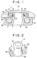
- FIG. 1 is an enlarged cross-sectional view of a cord stopper according to the present invention.
- FIG. 2 is a perspective view of a cord holder of the cord stopper of FIG. 1.
- FIG. 3 is a cross-sectional view of a cord stopper according to another embodiment of the present invention.
- FIG. 4 is a cross-sectional view of a cord stopper according to still another embodiment of the present invention.
- FIG. 5 is an exploded perspective view of the cord stopper of FIG. 4, showing a first phase of fastening of a cord to the cord stopper.
- FIG. 6 is a view similar to FIG. 5, showing a second phase of the fastening.
- FIG. 7 is a fragmental cross-sectional view of still another embodiment.
- FIG. 8 is a cross-sectional view of a cord stopper according to yet another embodiment.
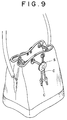
- a cord stopper S according to the present invention is shown to be used for fastening a cord around a mouth of a pouch. Nevertheless, the cord stopper S may be used for garments, baggages, shoes and the like material.
- a cord stopper S1 broadly comprises a substantially circular front body 11, an annular housing 13, an annular spring 15 and a cord holder 17.
- the circular front body 11 may be made of metal or plastics and may have its front side bear any decorative pattern or ornamental design.
- the circular front body 11 has a recess 19 formed in the rear side thereof.
- the annular housing 13 has an upper annular portion 21 and a lower annular portion 23 extending downward from the outer edge of the upper annular portion 21 and then radially inwardly to thus form a sear 25 for supporting the annular spring 15.
- the lower annular portion 23 has a central through hole 27 formed centrally thereof.
- the annular spring 15 is slightly less in diameter than the through hole 27 so that the annular spring 15 rests on the seat 25 with the inner peripheral part of the annular spring 15 appearing beyond the periphery of the through hole 27.
- the annular housing 13 is fixed to the circular front body 11 by attaching the upper annular portion 21 to the bottom of the recess 19 such as with adhesive.
- the cord holder 17 comprises a hollow truncated-conical body 31 and a pair of channel flanges 33, 33 disposed in diametrically opposed relation to each other and integrally extending radially outwardly from the lower edge 35 of the truncated conical body 31.
- Each channel 33, 33 is adapted to support a cord C therein.
- the truncated body 31 is flared at its upper end to provide an upper flared rim 37 which is slightly greater in diameter than the annular spring 15.
- the truncated-conical body 31 is thrust through the central through hole 27 and through the annular spring 15. As soon as the upper rim 37 of the truncated conical body 31 passes beyond the annular spring 15 and comes into coupling engagement therewith, the upper rim 37 and hence the cord holder 17 as a whole are retained to the annular spring 15 so that the cord C supported in the channel flanges 33 is firmly retained against the rear side of the circular front body 11.
- FIG. 3 shows a cord stopper S2 according to a second embodiment.
- the cord stopper S2 is substantially identical with that S1 according to the first embodiment except for the following two features.
- the cord- holder 40 of the cord stopper S2 is of three-piece construction and comprises a connector ring 41, a cord carrier 43 and a clamping tube 45.
- the connector ring 41 has its outer periphery flared upward and has an inner peripheral flange 47 extending radially inward from the lower edge thereof.
- the connector ring 41 is made slightly greater in diameter than the annular spring 15.
- the cord carrier 43 includes a truncated conical body 49 and a pair of channel flanges 51 disposed diametrically opposed relation to each other and integrally extending radially outwardly from the lower edge of the truncated conical body 49 for supporting the cord C therein.
- the truncated conical body 49 has an inner peripheral flange 53 formed along the upper rim thereof.
- the cord carrier 43 is joined to the bottom of the connector ring 41 by causing the clamping tube 45 to clamp the inner peripheral flanges 53, 47 of the cord carrier 43 and the connector ring 41, respectively.
- the annular housing 13' of the cord stopper S2 is two-piece construction and comprises an annular dish 28 having a central through hole 27 formed therein and a flat hood 29 mounted on the annular dish 28 by caulking or curling the periphery of the flat hood 29 over the peripheral edge of the annular dish 28.
- the thus assembled annular housing 13' is fixed to the front body 11 by attaching the flat hood 29 to the bottom of the recess 19 by means of adhesive or other suitable means.
- FIGS. 4, 5 and 6 show a cord stopper S3 according to a third embodiment of the present invention.
- the cord stopper S3 is substantially identical with the cord stopper S2 according to the second embodiment except that the channeled cord holder 40 of the cord stopper S2 is replaced with a truncated-conical base 61 and an elongated band or strip 67.
- the truncated-conical base 61 has a lower peripheral flange 63 integrally extending radially outwardly from its lower peripheral edge.
- the truncated-conical base 61 has at its upper end an upper flared rim 65 which is slightly greater in diameter than the annular spring 15.
- the elongated strip 67 is made of a somewhat flexible material such as leather, rubber, plastics or the like. As better shown in FIG. 6, the substantially rectangular strip 67 has a plurality of (three in FIG. 6) through holes 69 formed at intervals along the length thereof. Preferably, each hole 69 is slightly less in diameter than the upper flared rim 65 of the truncated-conical base 61 or the connector ring 41.
- the annular housing 13 is shown, here in FIG. 4, to comprise an annular dish 28 and a flat hood 29, the annular housing 13' may be formed as a one-piece part like the annular housing 13 shown in FIG. 1.
- FIG. 7 shows a truncated conical base 61 and a strip 67 which is substantially identical with those shown in FIG. 4 with the exception that the strip 67 has only two holes 69 so that it is only one cord C which the strip 67 is wrapped around.
- FIG. 8 shows a cord stopper S4 according to a fourth embodiment of the present invention.
- the cord stopper S4 is substantially identical with the cord stopper S3 according to the third embodiment with the following exception.
- Each of the housings 13, 13 has a central through hole 27 and has a seat 25 formed around the central through hole 27.
- Each annular spring 15 is slightly less in diameter than the through hole 27, so that the inner peripheral part of the annular spring 15 appears beyond the periphery of the central through hole 27.
- a cylinder 81 has a pair of flared rims 83 one formed at each end.
- the strap 67 is folded over itself, wrapping around the cord C.
- the cylinder 81 is first fitted through the holes 69 of the cord-wrapping strip 67 and then fitted at each rim 83 through the annular spring 15 so that the interposed cord-wrapping strap 67 is retentively held between the front bodies 11, 11. Since this cord stopper S4 has the dual front bodies 11, 11, the wearer may use this cord stopper S4 indiscriminately or without regard of which side is the front.
- cord stopper for adjusting the length of the cord C, it is only necessary to pull the cord C through the cord stopper.
- the present invention has the following advantageous effects.
- the cord stoppers may be assembled at great ease.
- the cord stoppers Since the assemblage of the cord stoppers requires no screw, the cord stoppers are immune from accidental loosening and subsequent loss of the screw which might occur with the conventional cord stoppers. Consequently, the cord stopper can accomplish satisfactory function for a prolonged period of time.
Landscapes
- Engineering & Computer Science (AREA)
- General Engineering & Computer Science (AREA)
- Mechanical Engineering (AREA)
- Adornments (AREA)
- Respiratory Apparatuses And Protective Means (AREA)
- Purses, Travelling Bags, Baskets, Or Suitcases (AREA)
- Ropes Or Cables (AREA)
Applications Claiming Priority (2)
| Application Number | Priority Date | Filing Date | Title |
|---|---|---|---|
| JP051102U JPH0613516U (ja) | 1992-07-21 | 1992-07-21 | 紐締具 |
| JP51102/92U | 1992-07-21 |
Publications (1)
| Publication Number | Publication Date |
|---|---|
| EP0580343A1 true EP0580343A1 (en) | 1994-01-26 |
Family
ID=12877452
Family Applications (1)
| Application Number | Title | Priority Date | Filing Date |
|---|---|---|---|
| EP93305468A Ceased EP0580343A1 (en) | 1992-07-21 | 1993-07-13 | Cord stopper |
Country Status (5)
| Country | Link |
|---|---|
| US (1) | US5337458A (ko) |
| EP (1) | EP0580343A1 (ko) |
| JP (1) | JPH0613516U (ko) |
| KR (1) | KR960001084Y1 (ko) |
| CN (1) | CN1085758A (ko) |
Cited By (1)
| Publication number | Priority date | Publication date | Assignee | Title |
|---|---|---|---|---|
| US9179751B2 (en) | 2013-07-28 | 2015-11-10 | Michael LEI | Adjustable keeper device |
Families Citing this family (8)
| Publication number | Priority date | Publication date | Assignee | Title |
|---|---|---|---|---|
| US6007245A (en) * | 1997-06-19 | 1999-12-28 | Corporate Air Parts, Inc. | Infrared cloaking emergency survival blanket |
| JP4519313B2 (ja) * | 2000-12-21 | 2010-08-04 | 株式会社ニフコ | 紐留め具 |
| US6675446B2 (en) * | 2001-08-27 | 2004-01-13 | J.A.M. Plastics, Inc. | Attachable neck lanyard slider |
| US7032276B1 (en) | 2003-06-17 | 2006-04-25 | Casey Olson | Adjustable snap buckle |
| US20080072386A1 (en) * | 2006-09-27 | 2008-03-27 | The Malish Corporation | Locking coupler for floor maintenance pad |
| US10527129B2 (en) | 2016-08-26 | 2020-01-07 | Nike, Inc. | Cord lock |
| CN213150159U (zh) * | 2018-06-06 | 2021-05-07 | 浙江伟星实业发展股份有限公司 | 一种吊牌止扣及具有该吊牌止扣的连接结构 |
| TWI675630B (zh) * | 2019-01-04 | 2019-11-01 | 程田有限公司 | 繩扣裝置 |
Citations (6)
| Publication number | Priority date | Publication date | Assignee | Title |
|---|---|---|---|---|
| US736306A (en) * | 1903-02-27 | 1903-08-11 | Edward D Smith | Shoe-lace fastener. |
| US3597808A (en) * | 1970-06-04 | 1971-08-10 | Philip L Johnson | Line clamp |
| JPS4914097Y1 (ko) * | 1969-10-15 | 1974-04-08 | ||
| US4258456A (en) * | 1979-06-13 | 1981-03-31 | Thurston Jay D | Shoelace holder |
| DE3300879A1 (de) * | 1981-07-14 | 1984-07-19 | Hammerlit Gmbh, 2950 Leer | Waeschesack mit einer, die verschlussblume des geschlossenen sackes umschlingenden kordel |
| JPH0228736Y2 (ko) * | 1986-06-10 | 1990-08-01 |
Family Cites Families (7)
| Publication number | Priority date | Publication date | Assignee | Title |
|---|---|---|---|---|
| US189274A (en) * | 1877-04-03 | Improvement in rope-clamps | ||
| US2134037A (en) * | 1937-05-12 | 1938-10-25 | Scovill Manufacturing Co | Fastener |
| GB769646A (en) * | 1955-05-09 | 1957-03-13 | Curtain cord equalizer | |
| US3074135A (en) * | 1960-04-12 | 1963-01-22 | John A Di Lorenzo | Releasible lace fastener device |
| JPS62228736A (ja) * | 1986-03-29 | 1987-10-07 | Takayuki Miyao | 歯車変速機 |
| US5008981A (en) * | 1989-12-01 | 1991-04-23 | Smithson Joseph P | Enclosed yoke clasp for bola-style necktie |
| US5175911A (en) * | 1990-03-23 | 1993-01-05 | Terrels Joseph L | Snap fastener |
-
1992
- 1992-07-21 JP JP051102U patent/JPH0613516U/ja active Pending
-
1993
- 1993-07-13 EP EP93305468A patent/EP0580343A1/en not_active Ceased
- 1993-07-20 KR KR2019930013478U patent/KR960001084Y1/ko not_active IP Right Cessation
- 1993-07-20 US US08/094,333 patent/US5337458A/en not_active Expired - Fee Related
- 1993-07-21 CN CN93108702A patent/CN1085758A/zh not_active Withdrawn
Patent Citations (6)
| Publication number | Priority date | Publication date | Assignee | Title |
|---|---|---|---|---|
| US736306A (en) * | 1903-02-27 | 1903-08-11 | Edward D Smith | Shoe-lace fastener. |
| JPS4914097Y1 (ko) * | 1969-10-15 | 1974-04-08 | ||
| US3597808A (en) * | 1970-06-04 | 1971-08-10 | Philip L Johnson | Line clamp |
| US4258456A (en) * | 1979-06-13 | 1981-03-31 | Thurston Jay D | Shoelace holder |
| DE3300879A1 (de) * | 1981-07-14 | 1984-07-19 | Hammerlit Gmbh, 2950 Leer | Waeschesack mit einer, die verschlussblume des geschlossenen sackes umschlingenden kordel |
| JPH0228736Y2 (ko) * | 1986-06-10 | 1990-08-01 |
Cited By (1)
| Publication number | Priority date | Publication date | Assignee | Title |
|---|---|---|---|---|
| US9179751B2 (en) | 2013-07-28 | 2015-11-10 | Michael LEI | Adjustable keeper device |
Also Published As
| Publication number | Publication date |
|---|---|
| KR960001084Y1 (ko) | 1996-02-07 |
| JPH0613516U (ja) | 1994-02-22 |
| US5337458A (en) | 1994-08-16 |
| KR940006954U (ko) | 1994-04-12 |
| CN1085758A (zh) | 1994-04-27 |
Similar Documents
| Publication | Publication Date | Title |
|---|---|---|
| JPS622903A (ja) | イヤリングのクラツチ機構及びクラツチ機構と組み合わされて使用される取り外し可能な荷重分散用部材 | |
| US5337458A (en) | Cord stopper | |
| US4486169A (en) | Cigarette lighter securing accessory | |
| US6196382B1 (en) | Cigarette lighter holder | |
| US5008984A (en) | Magnetic jewelry closure with clip | |
| US5156023A (en) | Multi-purpose pin for supporting jewelry or clothing accessories | |
| US5101541A (en) | Snap button | |
| US6675611B2 (en) | Necklace mount | |
| US6035494A (en) | Button | |
| US3041856A (en) | Ear ornament with three-point resilient support within the tragus, the antitragus and the anti-helix | |
| US6338419B1 (en) | Container | |
| KR101919760B1 (ko) | 스트랩 연결부재 | |
| US4627132A (en) | Belt clasp | |
| US2763999A (en) | Earring pads with expansible opening for attaching to earring | |
| USD411915S (en) | Backpack for holding liquid | |
| US20150282575A1 (en) | System and method for securing accessories to jewelry | |
| US20030093874A1 (en) | Fastening device | |
| KR970061141A (ko) | 컷트된 보석용 부착금구 및 장신구 | |
| US6079855A (en) | Detachable decorative system for lamp shades | |
| US4520536A (en) | Clothing clasp | |
| US6925838B1 (en) | Earring support device | |
| US4963136A (en) | Coupling for attaching an ostomy or pouch to a medical grade adhesive pad | |
| US4686837A (en) | Personal decoration retainer | |
| US5639000A (en) | Watch band assembly | |
| US2775014A (en) | Cushioning accessory for earrings |
Legal Events
| Date | Code | Title | Description |
|---|---|---|---|
| PUAI | Public reference made under article 153(3) epc to a published international application that has entered the european phase |
Free format text: ORIGINAL CODE: 0009012 |
|
| AK | Designated contracting states |
Kind code of ref document: A1 Designated state(s): DE ES FR GB IT |
|
| 17P | Request for examination filed |
Effective date: 19940613 |
|
| RAP1 | Party data changed (applicant data changed or rights of an application transferred) |
Owner name: YKK CORPORATION |
|
| 17Q | First examination report despatched |
Effective date: 19950515 |
|
| GRAG | Despatch of communication of intention to grant |
Free format text: ORIGINAL CODE: EPIDOS AGRA |
|
| STAA | Information on the status of an ep patent application or granted ep patent |
Free format text: STATUS: THE APPLICATION HAS BEEN REFUSED |
|
| 18R | Application refused |
Effective date: 19960921 |