EP0580197A2 - Device for making balls of dough or similar material - Google Patents
Device for making balls of dough or similar material Download PDFInfo
- Publication number
- EP0580197A2 EP0580197A2 EP93201833A EP93201833A EP0580197A2 EP 0580197 A2 EP0580197 A2 EP 0580197A2 EP 93201833 A EP93201833 A EP 93201833A EP 93201833 A EP93201833 A EP 93201833A EP 0580197 A2 EP0580197 A2 EP 0580197A2
- Authority
- EP
- European Patent Office
- Prior art keywords
- axis
- machine
- block
- cylinder
- dough
- Prior art date
- Legal status (The legal status is an assumption and is not a legal conclusion. Google has not performed a legal analysis and makes no representation as to the accuracy of the status listed.)
- Granted
Links
Images

Classifications
-
- A—HUMAN NECESSITIES
- A21—BAKING; EDIBLE DOUGHS
- A21C—MACHINES OR EQUIPMENT FOR MAKING OR PROCESSING DOUGHS; HANDLING BAKED ARTICLES MADE FROM DOUGH
- A21C7/00—Machines which homogenise the subdivided dough by working other than by kneading
- A21C7/005—Machines which homogenise the subdivided dough by working other than by kneading the dough pieces being worked in radially disposed cavities in a rotating drum
Definitions
- the present invention relates to a machine for placing in balls of baking dough or the like.
- the division operation and the successive phase of doughballing of the dough pieces are generally carried out automatically using machines of a well-known type, which are most often referred to as dividers and drum rounders.
- the dough is divided into dough pieces of uniform and predetermined weight, which are then deposited in suitable cavities formed in the outer wall of a rotating drum; after which the shaping action, which will be detailed below, allows said dough pieces to affect a substantially spherical profile.
- the ball-making station essentially comprises three elements, namely a rotating drum of cylindrical shape which has on its outer wall the above-mentioned cavities, an outer conveyor belt which advances at the peripheral speed of rotation of the drum in order to contain and retain the dough pieces in position, and finally a cylinder mounted inside the aforementioned drum.
- the movements accomplished by the cylinder inside the drum which constitutes the basic element on which each dough piece is supported in order to allow the dough to be shaped until bringing said dough piece to the substantially spherical profile, are very typical. These displacements are obtained by combination of two simultaneous movements, one of alternating rotation and the other of axial translation, also of alternating nature. By the effect of these two movements combined, each point on the outer surface of the cylinder travels an elliptical trajectory.
- the reciprocating rotational movement of the cylinder is obtained as a result of the displacement of its central shaft which comprises, at one of its ends, a radial extension provided with a ball joint.
- This ball joint is housed inside a block which rotates around a axis perpendicular to that of the cylinder.
- the rotation of the ball joint around this axis is transmitted to the central shaft, the movements of which are linked to displacement and rotation along its axis, which coincides with the axis of the machine.
- the object of the present invention is to produce a machine of the type described above which includes means making it possible to modify the trajectory of the points on the external surface of the cylinder.
- this variation may internvir even when the machine is in operation, which constitutes a notable advantage with regard to the productivity and the simplicity of operation of the assembly.
- the machine is provided with means which make it possible to modify the distance which separates the ball joint from the axis of the aforementioned block, perpendicular to that of the cylinder. More particularly, this is obtained by ensuring that around the block which incorporates the aforementioned ball joint, there is provided a conical toothed wheel whose axis coincides with that of the block, which wheel is capable of being rotated by another bevel gear wedged on a shaft co-axial with the central shaft, the first bevel wheel being externally secured to a toothed ring capable of cooperating with a pinion provided at the end of a threaded rod which is screwed on the part of the block which is hollowed out of the cavity in which the ball joint is inserted; the movements of the first toothed wheel thus determine the modification of the distance between the rod at the level of which the above-mentioned ball joint and axis are provided.
- the invention further comprises, in one of its secondary claims, a particular embodiment essentially targeting the means suitable for ensuring the setting in motion of the above-mentioned kinematic chain, in order to obtain the variation of the 'center distance.
- the balling machine visible in fig. 1 to 3 is essentially constituted, in the manner known per se, by a transfer station 1 which brings the pieces of pasta or dough to work, by a drum 2 whose side wall has cavities 3 inside which come s 'engage the dough pieces having a determined weight, by a cylinder 4 disposed inside said drum 2, and finally by an endless belt 5 which is partially wound on the drum 1 and which acts as a final evacuation conveyor.
- the group 7 which is intended for driving the drum 2 and the cylinder 4 and which is mounted idly on bearings 8 provided inside the frame cited above.
- the setting in motion of the kinematic chain enclosed by the group 7, as well as the rotation thereof, are obtained by means of two electric motors 9 and 10 carried by the frame 6.
- the motor 9 drives in rotation by the chain 11 the outer casing 12 of group 7, along the longitudinal axis 13 of the machine.
- the projecting side part 14 of the outer casing 12 is connected to the drum 2 which is thus rotated about the axis 13.
- the motor 10 is capable of rotating the control shaft 16, itself oriented along the axis 13 of the machine; at the end of this shaft 16 is wedged a conical toothed wheel 17 which in turn cooperates with a conical toothed wheel 18 formed on the lower part of a block 19, which is thus rotated about a perpendicular axis 20 to the longitudinal axis 13.
- the bearing 21 serves as a guide and support element for the block 19 provided inside the casing 12.
- the cylinder 4 is wedged on the central shaft 23, which moves inside the projecting part 14 while being supported by bearings 24.
- a rod 25 provided at the end of a ball joint 26.
- the ball joint 26 penetrates inside a housing 28 formed in the block 19, and it cooperates with a seat 27.
- the block 19 is forced to rotate both around the axis 13 and around the axis 20. More precisely, the rotation of the aforementioned block around the axis 20 puts in motion the shaft 23, so that all the points on the outer face of the cylinder 4 complete an elliptical trajectory, which makes it possible to exert an effective operation on the dough pieces placed in the cavities 3.
- the originality of the invention consists in an arrangement suitable for determining the displacement of the seat 27 and, under these conditions, for varying the radius of rotation of the ball 26 around the axis 20, and this even when the machine is Operating.
- a pinion 29 adapted to transmit the movement to a variable speed drive 30 on the control shaft 16. (of the type commonly called differential) carried by the machine frame.
- the output pinion 31 of this differential 30 rotates, by a toothed wheel 32, a bevel gear 33 which is mounted idly, by means of bearings 34 on the control shaft 16.
- the bearings 35 make it possible to make reciprocally independent the rotation of the block 12 and the rotation of the hub 36 of the toothed wheel 33.
- the differential 30 sets in motion the output kinematic chain constituted by the toothed wheels 31, 32, 33 and 37, so that the latter rotates at the same angular speed as that which drives the block 19 around of the axis 20. Under these conditions, the pinion 39 therefore remains stationary.
Abstract
Description
La présente invention a pour objet une machine pour la mise en boules de la pâte de boulange ou similaire.The present invention relates to a machine for placing in balls of baking dough or the like.
L'une des différentes opérations qui sont effectuées dans l'industrie de la panification réside dans la division et la mise en boules de la pâte, en vue de la formation de pâtons de forme substantiellement sphérique destinés à être ensuite soumis à la cuisson.One of the various operations which are carried out in the bread-making industry resides in the division and the placing in balls of the dough, with a view to the formation of dough pieces of substantially spherical shape intended to be then subjected to baking.
L'opération de division et la phase successive de mise en boules des pâtons sont généralement effectuées de manière automatique à l'aide de machines de type bien connu, qui sont le plus souvent désignées sous les noms de diviseuses et de bouleuses à tambour. Dans ces machines, la pâte est divisée en pâtons de poids uniforme et prédéterminé, qui sont ensuite déposés dans des cavités appropriées ménagées dans la paroi extérieure d'un tambour tournant; après quoi l'action de conformation, qui sera détaillée ci-après, permet auxdits pâtons d'affecter un profil substantiellement sphérique.The division operation and the successive phase of doughballing of the dough pieces are generally carried out automatically using machines of a well-known type, which are most often referred to as dividers and drum rounders. In these machines, the dough is divided into dough pieces of uniform and predetermined weight, which are then deposited in suitable cavities formed in the outer wall of a rotating drum; after which the shaping action, which will be detailed below, allows said dough pieces to affect a substantially spherical profile.
Le poste de mise en boules comprend essentiellement trois éléments, à savoir un tambour tournant de forme cylindrique qui comporte sur sa paroi extérieure les cavités sus-indiquées, un tapis transporteur extérieur qui avance à la vitesse périphérique de rotation du tambour afin de contenir et de retenir en position les pâtons, et enfin un cylindre monté à l'intérieur du tambour sus-mentionné.The ball-making station essentially comprises three elements, namely a rotating drum of cylindrical shape which has on its outer wall the above-mentioned cavities, an outer conveyor belt which advances at the peripheral speed of rotation of the drum in order to contain and retain the dough pieces in position, and finally a cylinder mounted inside the aforementioned drum.
Les déplacements accomplis par le cylindre à l'intérieur du tambour qui constitue l'élément de base sur lequel prend appui chaque pâton en vue de permettre la conformation de la pâte jusqu'à amener ledit pâton au profil substantiellement sphérique, sont bien typiques. Ces déplacements sont obtenus par combinaison de deux mouvements simultanés, l'un de rotation alternée et l'autre de translation axiale, également de nature alternée. Par l'effet de ces deux mouvements combinés, chaque point de la surface extérieure du cylindre parcourt une trajectoire elliptique. Le mouvement de roto-translation alternatif du cylindre est obtenu par suite du déplacement de son arbre central qui comporte, au niveau de l'une de ses extrémités, un prolongement radial pourvu d'une rotule.The movements accomplished by the cylinder inside the drum which constitutes the basic element on which each dough piece is supported in order to allow the dough to be shaped until bringing said dough piece to the substantially spherical profile, are very typical. These displacements are obtained by combination of two simultaneous movements, one of alternating rotation and the other of axial translation, also of alternating nature. By the effect of these two movements combined, each point on the outer surface of the cylinder travels an elliptical trajectory. The reciprocating rotational movement of the cylinder is obtained as a result of the displacement of its central shaft which comprises, at one of its ends, a radial extension provided with a ball joint.
Cette rotule est logée à l'intérieur d'un bloc qui tourne autour d'un axe perpendiculaire à celui du cylindre. La rotation de la rotule autour de cet axe est transmise à l'arbre central dont les mouvements sont liés au déplacement et à la rotation le long de son axe, lequel coïncide avec l'axe de la machine.This ball joint is housed inside a block which rotates around a axis perpendicular to that of the cylinder. The rotation of the ball joint around this axis is transmitted to the central shaft, the movements of which are linked to displacement and rotation along its axis, which coincides with the axis of the machine.
Dans ces conditions, on comprend sans peine que lorsque la rotule aura accompli une rotation complète autour de l'axe perpendiculaire à celui de la machine, le cylindre aura lui-même subi un déplacement alternatif dans le sens longitudinal suivant son axe et, simultanément, aura accompli également une rotation, toujours alternative, d'un certain nombre de dégrés autour de l'axe précité.Under these conditions, it is easily understood that when the ball joint has completed a complete rotation around the axis perpendicular to that of the machine, the cylinder will itself have undergone an alternating movement in the longitudinal direction along its axis and, simultaneously, will also have completed a rotation, always alternative, of a certain number of degrees around the aforementioned axis.
En fonction du type de la pâte à travailler ou du poids des pâtons élémentaires à obtenir, il serait avantageux de pouvoir régler les mouvements du cylindre et, plus particulièrement, la trajectoire elliptique des points de sa surface externe, cette trajectoire constituant essentiellement le paramètre qui détermine la mise en boule du pâton.Depending on the type of dough to be worked or the weight of the elementary dough to be obtained, it would be advantageous to be able to adjust the movements of the cylinder and, more particularly, the elliptical trajectory of the points of its external surface, this trajectory constituting essentially the parameter which determines the dough balling.
Le but de la présente invention est de réaliser une machine du type précédemment décrit qui comporte des moyens permettant de modifier la trajectoire des points de la surface extérieure du cylindre. En particulier, cette variation pourra internevir même lorsque la machine est en fonctionnement, ce qui constitue un avantage notable en ce qui concerne la productivité et la simplicité de fonctionnement de l'ensemble.The object of the present invention is to produce a machine of the type described above which includes means making it possible to modify the trajectory of the points on the external surface of the cylinder. In particular, this variation may internvir even when the machine is in operation, which constitutes a notable advantage with regard to the productivity and the simplicity of operation of the assembly.
La machine suivant l'invention est définie à la revendication 1.The machine according to the invention is defined in claim 1.
En fait la machine est dotée de moyens qui permettent de modifier la distance qui sépare la rotule de l'axe du bloc précité, perpendiculaire à celui du cylindre. Plus particulièrement, ceci est obtenu en faisant en sorte qu'autour du bloc qui incorpore la rotule précitée, soit prévue une roue dentée conique dont l'axe coïncide avec celui du bloc, laquelle roue est susceptible d'être mise en rotation par une autre roue conique calée sur un arbre co-axial à l'arbre central, la première roue conique étant extérieurement solidaire d'une couronne dentée propre à coopérer avec un pignon prévu à l'extrémité d'une tige filetée qui se visse sur la partie du bloc qui est creusée de la cavité dans laquelle est insérée la rotule ; les mouvements de la première roue dentée déterminent ainsi la modification de l'entraxe existant entre la tige au niveau de laquelle est prévue la rotule et l'axe du bloc susmentionné.In fact the machine is provided with means which make it possible to modify the distance which separates the ball joint from the axis of the aforementioned block, perpendicular to that of the cylinder. More particularly, this is obtained by ensuring that around the block which incorporates the aforementioned ball joint, there is provided a conical toothed wheel whose axis coincides with that of the block, which wheel is capable of being rotated by another bevel gear wedged on a shaft co-axial with the central shaft, the first bevel wheel being externally secured to a toothed ring capable of cooperating with a pinion provided at the end of a threaded rod which is screwed on the part of the block which is hollowed out of the cavity in which the ball joint is inserted; the movements of the first toothed wheel thus determine the modification of the distance between the rod at the level of which the above-mentioned ball joint and axis are provided.
Cet agencement permet à lui-seul d'autoriser la variation de l'entraxe sus-mentionné, même lorsque la machine fonctionne normalement.This arrangement alone allows the variation of the above-mentioned center distance to be authorized, even when the machine is operating normally.
L'invention comprend en outre, dans l'une de ses revendications secondaires, une forme particulière de réalisation visant essentiellement les moyens propres à assurer la mise en mouvement de la chaîne cinématique sus-indiquée, dans le but d'obtenir la variation de l'entraxe.The invention further comprises, in one of its secondary claims, a particular embodiment essentially targeting the means suitable for ensuring the setting in motion of the above-mentioned kinematic chain, in order to obtain the variation of the 'center distance.
L'invention va maintenant être illustrée dans une de ses formes particulières de réalisation, donnée à titre d'exemple non limitatif, avec l'aide des planches de dessin annexées, dans lesquelles :
- La fig. 1 est une coupe longitudinale schématique de la machine.
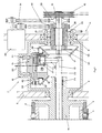
- La fig. 2 est une coupe longitudinale montrant à plus grande échelle l'agencement suivant l'invention.
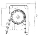
- La fig. 3 est une coupe transversale suivant le plan indiqué par la ligne II-II de fig. 1.
- Fig. 1 is a schematic longitudinal section of the machine.
- Fig. 2 is a longitudinal section showing on a larger scale the arrangement according to the invention.
- Fig. 3 is a cross section along the plane indicated by line II-II of FIG. 1.
La machine de mise en boules visible en fig. 1 à 3 est essentiellement constituée, à la façon en soi connue, par un poste de transfert 1 qui amène les morceaux de pâtes ou pâtons à travailler, par un tambour 2 dont la paroi latérale comporte des cavités 3 à l'intérieur desquelles viennent s'engager les pâtons présentant un poids déterminé, par un cylindre 4 disposé à l'intérieur dudit tambour 2, et enfin par un tapis sans fin 5 qui s'enroule partiellement sur le tambour 1 et qui fait fonction de transporteur final d'évacuation.The balling machine visible in fig. 1 to 3 is essentially constituted, in the manner known per se, by a transfer station 1 which brings the pieces of pasta or dough to work, by a
Comme on peut le voir en fig. 1 et 2, à l'intérieur du bâti général 6 de la machine est disposé le groupe 7 qui est destiné à l'entraînement du tambour 2 et du cylindre 4 et qui est monté fou sur des paliers 8 prévus à l'intérieur du bâti précité. La mise en mouvement de la chaîne cinématique renfermée par le groupe 7, ainsi que la rotation de celui-ci, sont obtenues au moyen de deux moteurs électriques 9 et 10 portés par le bâti 6. Le moteur 9 entraîne en rotation par la chaîne 11 le carter extérieur 12 du groupe 7, suivant l'axe longitudinal 13 de la machine. La partie latérale en saillie 14 du carter extérieur 12 est reliée au tambour 2 qui est ainsi mis en rotation autour de l'axe 13.As can be seen in fig. 1 and 2, inside the
A travers une transmission par courroie 15, le moteur 10 est propre à mettre en rotation l'arbre de commande 16, lui-même orienté suivant l'axe 13 de la machine ; à l'extrémité de cet arbre 16 est calée une roue dentée conique 17 qui à son tour coopère avec une roue dentée conique 18 ménagée sur la partie inférieure d'un bloc 19, lequel est ainsi entraîné en rotation autour d'un axe 20 perpendiculaire à l'axe longitudinal 13.Through a
Le palier 21 sert d'élément de guidage et de support pour le bloc 19 prévu à l'intérieur du carter 12.The
Le cylindre 4 est calé sur l'arbre central 23, lequel se déplace à l'intérieur de la partie en saillie 14 en étant supporté par des paliers 24.The cylinder 4 is wedged on the
A l'extrémité de l'arbre 23 est fixée une tige 25 pourvue en bout d'une rotule 26. La rotule 26 pénètre à l'intérieur d'un logement 28 ménagé dans le bloc 19, et elle coopère avec un siège 27.At the end of the
Des explications qui précèdent, on peut voir que le bloc 19 est obligé de tourner aussi bien autour de l'axe 13 qu'autour de l'axe 20. De manière plus précise, la rotation du bloc précité autour de l'axe 20 met en mouvement l'arbre 23, si bien que tous les points de la face extérieure du cylindre 4 accomplissent une trajectoire elliptique, laquelle permet d'exercer une opération efficace sur les pâtons disposés dans les cavités 3.From the foregoing explanations, it can be seen that the
Toute la construction qui vient d'être décrite correspond à l'état actuel de la technique.The whole construction which has just been described corresponds to the current state of the art.
L'originalité de l'invention consiste dans un agencement propre à déterminer le déplacement du siège 27 et, dans ces conditions, à faire varier le rayon de rotation de la rotule 26 autour de l'axe 20, et cela même lorsque la machine est en fonctionnement.The originality of the invention consists in an arrangement suitable for determining the displacement of the
A cet effet, on prévoit que sur l'arbre de commande 16 est calé un pignon 29 propre à transmettre le mouvement à un variateur de vitesse 30 (du type communément appelé différentiel) porté par le bâti de la machine. Le pignon de sortie 31 de ce différentiel 30 met en rotation, par une roue dentée 32, une roue dentée conique 33 qui est montée folle, par l'intermédiaire de paliers 34 sur l'arbre de commande 16. Les paliers 35 permettent de rendre réciproquement indépendantes la rotation du bloc 12 et la rotation du moyeu 36 de la roue dentée 33.To this end, provision is made for a
Cette dernière coopère avec une autre roue dentée conique 37 qui est montée folle autour du bloc 19 et qui porte extérieurement une autre couronne dentée 38, laquelle engrène avec un pignon 39. Ce dernier commande la rotation d'une tige fileté 40 qui est vissée dans un bossage du siège 27 qui reçoit la rotule 26.The latter cooperates with another conical
Lorsque la machine est en fonctionnement, le différentiel 30 met en mouvement la chaîne cinématique de sortie constituée par les roues dentées 31, 32, 33 et 37, de sorte que cette dernière tourne à la même vitesse angulaire que celle qui anime le bloc 19 autour de l'axe 20. Dans ces conditions, le pignon 39 reste donc immobile.When the machine is in operation, the differential 30 sets in motion the output kinematic chain constituted by the
Par contre, lorsqu'il est nécessaire de modifier le rayon de rotation de la rotule 26 autour de l'axe 20, on intervient sur le différentiel 30, qui grâce aux éléments de la chaîne cinématique ci-dessus décrite détermine la rotation du pignon 39 et ainsi le vissage ou dévissage de la tige 10, engendrant le déplacement du siège 27, de la rotule 26, dans un sens ou dans l'autre.On the other hand, when it is necessary to modify the radius of rotation of the
En conséquence on peut finalement constater que la variation de l'entraxe dont il a été question ci-dessus peut être sans autre difficulté effectuée même lorsque la machine est en fonctionnement. Au surplus, ce type de réglage a l'avantage de permettre une variation continue du paramètre envisagé, avec évidemment tous les avantages qui s'ensuivent pour l'utilisateur.Consequently, it can finally be seen that the variation in the center distance mentioned above can be carried out without other difficulty even when the machine is in operation. In addition, this type of adjustment has the advantage of allowing a continuous variation of the envisaged parameter, with obviously all the advantages which follow for the user.
Claims (5)
Applications Claiming Priority (2)
| Application Number | Priority Date | Filing Date | Title |
|---|---|---|---|
| ITVI920109 | 1992-07-01 | ||
| ITVI920109A IT1258598B (en) | 1992-07-01 | 1992-07-01 | ROUNDING MACHINE FOR WORKING FOOD PASTA |
Publications (3)
| Publication Number | Publication Date |
|---|---|
| EP0580197A2 true EP0580197A2 (en) | 1994-01-26 |
| EP0580197A3 EP0580197A3 (en) | 1994-09-07 |
| EP0580197B1 EP0580197B1 (en) | 1998-08-26 |
Family
ID=11424976
Family Applications (1)
| Application Number | Title | Priority Date | Filing Date |
|---|---|---|---|
| EP93201833A Expired - Lifetime EP0580197B1 (en) | 1992-07-01 | 1993-06-24 | Device for making balls of dough or similar material |
Country Status (4)
| Country | Link |
|---|---|
| EP (1) | EP0580197B1 (en) |
| AT (1) | ATE170043T1 (en) |
| DE (1) | DE69320562T2 (en) |
| IT (1) | IT1258598B (en) |
Cited By (2)
| Publication number | Priority date | Publication date | Assignee | Title |
|---|---|---|---|---|
| EP1449438A3 (en) * | 2003-02-15 | 2007-06-13 | Werner & Pfleiderer Lebensmitteltechnik GmbH | Dough processing installation |
| CN104605216A (en) * | 2015-01-26 | 2015-05-13 | 上海贸燊机电科技有限公司 | Food pasting and baking device |
Families Citing this family (2)
| Publication number | Priority date | Publication date | Assignee | Title |
|---|---|---|---|---|
| DE102012216201A1 (en) * | 2012-09-12 | 2014-03-13 | Neuenkirchener Maschinenfabrik Emil Kemper Gmbh | Three-engine operating drum arrangement |
| AT519197B1 (en) * | 2016-10-07 | 2018-08-15 | Koenig Maschinen Gmbh | Adjustable operating eccentric |
Citations (1)
| Publication number | Priority date | Publication date | Assignee | Title |
|---|---|---|---|---|
| EP0347553A1 (en) * | 1988-06-22 | 1989-12-27 | Werner & Pfleiderer GmbH | Device for rolling balls of dough |
-
1992
- 1992-07-01 IT ITVI920109A patent/IT1258598B/en active IP Right Grant
-
1993
- 1993-06-24 EP EP93201833A patent/EP0580197B1/en not_active Expired - Lifetime
- 1993-06-24 DE DE69320562T patent/DE69320562T2/en not_active Expired - Fee Related
- 1993-06-24 AT AT93201833T patent/ATE170043T1/en not_active IP Right Cessation
Patent Citations (1)
| Publication number | Priority date | Publication date | Assignee | Title |
|---|---|---|---|---|
| EP0347553A1 (en) * | 1988-06-22 | 1989-12-27 | Werner & Pfleiderer GmbH | Device for rolling balls of dough |
Cited By (3)
| Publication number | Priority date | Publication date | Assignee | Title |
|---|---|---|---|---|
| EP1449438A3 (en) * | 2003-02-15 | 2007-06-13 | Werner & Pfleiderer Lebensmitteltechnik GmbH | Dough processing installation |
| CN104605216A (en) * | 2015-01-26 | 2015-05-13 | 上海贸燊机电科技有限公司 | Food pasting and baking device |
| CN104605216B (en) * | 2015-01-26 | 2023-08-08 | 上海贸燊机电科技有限公司 | Food pasting and baking device |
Also Published As
| Publication number | Publication date |
|---|---|
| EP0580197A3 (en) | 1994-09-07 |
| DE69320562D1 (en) | 1998-10-01 |
| IT1258598B (en) | 1996-02-27 |
| ITVI920109A1 (en) | 1994-01-01 |
| DE69320562T2 (en) | 1999-04-22 |
| ATE170043T1 (en) | 1998-09-15 |
| EP0580197B1 (en) | 1998-08-26 |
| ITVI920109A0 (en) | 1992-07-01 |
Similar Documents
| Publication | Publication Date | Title |
|---|---|---|
| EP0371896B1 (en) | Device for marking by micro-percussion | |
| EP0141745B1 (en) | Automatic machine for bending thin and rectilinear elements, especially metal wire, into a spatial configuration | |
| FR2641722A1 (en) | DEVICE FOR DRIVING A TOOL HOLDER PIN | |
| FR2495898A1 (en) | DEVICE FOR SIMULTANEOUSLY CUTTING TWO CONTINUOUS CIGARETTE RODS PRODUCED BY A CIGARETTE MANUFACTURING MACHINE | |
| EP0090744B1 (en) | Machine comprising an annnular saw for cutting-off tubes | |
| EP0580197B1 (en) | Device for making balls of dough or similar material | |
| EP0258136B1 (en) | Method and apparatus for cutting objects of hard material without cutting objects of softer material | |
| CH679636A5 (en) | ||
| FR2556567A1 (en) | METHOD FOR SPACING AND RETURNING TWO COAXIAL CIGARETTE LENGTHS ON A FILTER MOUNTING MACHINE | |
| FR2501546A1 (en) | APPARATUS FOR FORMING A LARGE EDGE HOLE IN THE WALL OF A PIPE | |
| CH618660A5 (en) | ||
| FR2817251A1 (en) | APPARATUS FOR APPLYING A CABLE TO A ROTATING SURFACE | |
| EP0869858B1 (en) | Machining unit with rotating head | |
| FR2469965A2 (en) | METHOD AND DEVICE FOR MANUFACTURING HELICOIDAL SPRINGS | |
| FR2610858A1 (en) | ASSEMBLY OF MOTORIZING ELEMENTS OF THE WORKPIECE TABLE OF AN AUTOMATIC GEAR SIZING MACHINE | |
| EP3837074B1 (en) | Orbital drilling device | |
| EP0473739B1 (en) | Device for straightening a wire | |
| FR2633863A1 (en) | Handling robot with circular horizontal movement | |
| FR2467028A1 (en) | SPRING WINDING MACHINE PROVIDED WITH IMPROVED MEANS FOR DRIVING FEED ROLLERS | |
| FR2486120A1 (en) | HANDLE CONTROL DEVICE FOR SOIL COMPACTION APPARATUS | |
| EP0224419A1 (en) | In situ machining or measuring method and apparatus for a rotating work piece | |
| EP0302922B1 (en) | Device for the continuous manufacture by extrusion of a tube provided with spiral threads | |
| EP0086499A1 (en) | Apparatus for decorating pastry and bakery products | |
| FR2584689A1 (en) | FLAP DEVICE FOR BANDS OF MATERIALS TO BE WOUNDED. | |
| FR2478517A1 (en) | METHOD AND DEVICE FOR CONTROLLING MOVEMENTS IN ADVANCE AND CLEARANCE, ESPECIALLY IN WOOD SLICERS |
Legal Events
| Date | Code | Title | Description |
|---|---|---|---|
| PUAI | Public reference made under article 153(3) epc to a published international application that has entered the european phase |
Free format text: ORIGINAL CODE: 0009012 |
|
| AK | Designated contracting states |
Kind code of ref document: A2 Designated state(s): AT BE CH DE DK ES FR GB GR IE IT LI LU MC NL PT SE |
|
| PUAL | Search report despatched |
Free format text: ORIGINAL CODE: 0009013 |
|
| AK | Designated contracting states |
Kind code of ref document: A3 Designated state(s): AT BE CH DE DK ES FR GB GR IE IT LI LU MC NL PT SE |
|
| 17P | Request for examination filed |
Effective date: 19950216 |
|
| 17Q | First examination report despatched |
Effective date: 19961216 |
|
| GRAG | Despatch of communication of intention to grant |
Free format text: ORIGINAL CODE: EPIDOS AGRA |
|
| GRAG | Despatch of communication of intention to grant |
Free format text: ORIGINAL CODE: EPIDOS AGRA |
|
| GRAH | Despatch of communication of intention to grant a patent |
Free format text: ORIGINAL CODE: EPIDOS IGRA |
|
| GRAH | Despatch of communication of intention to grant a patent |
Free format text: ORIGINAL CODE: EPIDOS IGRA |
|
| GRAA | (expected) grant |
Free format text: ORIGINAL CODE: 0009210 |
|
| AK | Designated contracting states |
Kind code of ref document: B1 Designated state(s): AT BE CH DE DK ES FR GB GR IE IT LI LU MC NL PT SE |
|
| PG25 | Lapsed in a contracting state [announced via postgrant information from national office to epo] |
Ref country code: GR Free format text: LAPSE BECAUSE OF NON-PAYMENT OF DUE FEES Effective date: 19980826 Ref country code: GB Free format text: LAPSE BECAUSE OF FAILURE TO SUBMIT A TRANSLATION OF THE DESCRIPTION OR TO PAY THE FEE WITHIN THE PRESCRIBED TIME-LIMIT Effective date: 19980826 Ref country code: FR Free format text: THE PATENT HAS BEEN ANNULLED BY A DECISION OF A NATIONAL AUTHORITY Effective date: 19980826 Ref country code: ES Free format text: THE PATENT HAS BEEN ANNULLED BY A DECISION OF A NATIONAL AUTHORITY Effective date: 19980826 |
|
| REF | Corresponds to: |
Ref document number: 170043 Country of ref document: AT Date of ref document: 19980915 Kind code of ref document: T |
|
| REG | Reference to a national code |
Ref country code: CH Ref legal event code: EP |
|
| REF | Corresponds to: |
Ref document number: 69320562 Country of ref document: DE Date of ref document: 19981001 |
|
| REG | Reference to a national code |
Ref country code: IE Ref legal event code: FG4D Free format text: FRENCH |
|
| PG25 | Lapsed in a contracting state [announced via postgrant information from national office to epo] |
Ref country code: SE Free format text: LAPSE BECAUSE OF FAILURE TO SUBMIT A TRANSLATION OF THE DESCRIPTION OR TO PAY THE FEE WITHIN THE PRESCRIBED TIME-LIMIT Effective date: 19981126 Ref country code: PT Free format text: LAPSE BECAUSE OF FAILURE TO SUBMIT A TRANSLATION OF THE DESCRIPTION OR TO PAY THE FEE WITHIN THE PRESCRIBED TIME-LIMIT Effective date: 19981126 Ref country code: DK Free format text: LAPSE BECAUSE OF FAILURE TO SUBMIT A TRANSLATION OF THE DESCRIPTION OR TO PAY THE FEE WITHIN THE PRESCRIBED TIME-LIMIT Effective date: 19981126 |
|
| GBV | Gb: ep patent (uk) treated as always having been void in accordance with gb section 77(7)/1977 [no translation filed] |
Effective date: 19980826 |
|
| PG25 | Lapsed in a contracting state [announced via postgrant information from national office to epo] |
Ref country code: IE Free format text: LAPSE BECAUSE OF NON-PAYMENT OF DUE FEES Effective date: 19990504 |
|
| PG25 | Lapsed in a contracting state [announced via postgrant information from national office to epo] |
Ref country code: LU Free format text: LAPSE BECAUSE OF NON-PAYMENT OF DUE FEES Effective date: 19990624 |
|
| PG25 | Lapsed in a contracting state [announced via postgrant information from national office to epo] |
Ref country code: LI Free format text: LAPSE BECAUSE OF NON-PAYMENT OF DUE FEES Effective date: 19990630 Ref country code: CH Free format text: LAPSE BECAUSE OF NON-PAYMENT OF DUE FEES Effective date: 19990630 Ref country code: BE Free format text: LAPSE BECAUSE OF NON-PAYMENT OF DUE FEES Effective date: 19990630 |
|
| PGFP | Annual fee paid to national office [announced via postgrant information from national office to epo] |
Ref country code: NL Payment date: 19990630 Year of fee payment: 7 |
|
| REG | Reference to a national code |
Ref country code: IE Ref legal event code: FD4D |
|
| PLBE | No opposition filed within time limit |
Free format text: ORIGINAL CODE: 0009261 |
|
| STAA | Information on the status of an ep patent application or granted ep patent |
Free format text: STATUS: NO OPPOSITION FILED WITHIN TIME LIMIT |
|
| 26N | No opposition filed | ||
| BERE | Be: lapsed |
Owner name: COSTRUZIONI MECCHANICHE SOTTORIVA S.P.A. Effective date: 19990630 |
|
| PG25 | Lapsed in a contracting state [announced via postgrant information from national office to epo] |
Ref country code: MC Free format text: LAPSE BECAUSE OF NON-PAYMENT OF DUE FEES Effective date: 19991231 |
|
| REG | Reference to a national code |
Ref country code: CH Ref legal event code: PL |
|
| REG | Reference to a national code |
Ref country code: FR Ref legal event code: ST |
|
| PG25 | Lapsed in a contracting state [announced via postgrant information from national office to epo] |
Ref country code: NL Free format text: LAPSE BECAUSE OF NON-PAYMENT OF DUE FEES Effective date: 20010101 |
|
| NLV4 | Nl: lapsed or anulled due to non-payment of the annual fee |
Effective date: 20010101 |
|
| PGFP | Annual fee paid to national office [announced via postgrant information from national office to epo] |
Ref country code: AT Payment date: 20010613 Year of fee payment: 9 |
|
| PGFP | Annual fee paid to national office [announced via postgrant information from national office to epo] |
Ref country code: DE Payment date: 20010828 Year of fee payment: 9 |
|
| PG25 | Lapsed in a contracting state [announced via postgrant information from national office to epo] |
Ref country code: AT Free format text: LAPSE BECAUSE OF NON-PAYMENT OF DUE FEES Effective date: 20020624 |
|
| PG25 | Lapsed in a contracting state [announced via postgrant information from national office to epo] |
Ref country code: DE Free format text: LAPSE BECAUSE OF NON-PAYMENT OF DUE FEES Effective date: 20030101 |
|
| PG25 | Lapsed in a contracting state [announced via postgrant information from national office to epo] |
Ref country code: IT Free format text: LAPSE BECAUSE OF NON-PAYMENT OF DUE FEES;WARNING: LAPSES OF ITALIAN PATENTS WITH EFFECTIVE DATE BEFORE 2007 MAY HAVE OCCURRED AT ANY TIME BEFORE 2007. THE CORRECT EFFECTIVE DATE MAY BE DIFFERENT FROM THE ONE RECORDED. Effective date: 20050624 |