EP0580116A2 - Information managing apparatus - Google Patents
Information managing apparatus Download PDFInfo
- Publication number
- EP0580116A2 EP0580116A2 EP93111582A EP93111582A EP0580116A2 EP 0580116 A2 EP0580116 A2 EP 0580116A2 EP 93111582 A EP93111582 A EP 93111582A EP 93111582 A EP93111582 A EP 93111582A EP 0580116 A2 EP0580116 A2 EP 0580116A2
- Authority
- EP
- European Patent Office
- Prior art keywords
- information
- data
- key
- mode
- address
- Prior art date
- Legal status (The legal status is an assumption and is not a legal conclusion. Google has not performed a legal analysis and makes no representation as to the accuracy of the status listed.)
- Granted
Links
Images


Classifications
-
- G—PHYSICS
- G06—COMPUTING; CALCULATING OR COUNTING
- G06F—ELECTRIC DIGITAL DATA PROCESSING
- G06F15/00—Digital computers in general; Data processing equipment in general
- G06F15/02—Digital computers in general; Data processing equipment in general manually operated with input through keyboard and computation using a built-in program, e.g. pocket calculators
- G06F15/0225—User interface arrangements, e.g. keyboard, display; Interfaces to other computer systems
-
- G—PHYSICS
- G06—COMPUTING; CALCULATING OR COUNTING
- G06F—ELECTRIC DIGITAL DATA PROCESSING
- G06F15/00—Digital computers in general; Data processing equipment in general
- G06F15/02—Digital computers in general; Data processing equipment in general manually operated with input through keyboard and computation using a built-in program, e.g. pocket calculators
- G06F15/025—Digital computers in general; Data processing equipment in general manually operated with input through keyboard and computation using a built-in program, e.g. pocket calculators adapted to a specific application
- G06F15/0266—Digital computers in general; Data processing equipment in general manually operated with input through keyboard and computation using a built-in program, e.g. pocket calculators adapted to a specific application for time management, e.g. calendars, diaries
-
- G—PHYSICS
- G06—COMPUTING; CALCULATING OR COUNTING
- G06Q—INFORMATION AND COMMUNICATION TECHNOLOGY [ICT] SPECIALLY ADAPTED FOR ADMINISTRATIVE, COMMERCIAL, FINANCIAL, MANAGERIAL OR SUPERVISORY PURPOSES; SYSTEMS OR METHODS SPECIALLY ADAPTED FOR ADMINISTRATIVE, COMMERCIAL, FINANCIAL, MANAGERIAL OR SUPERVISORY PURPOSES, NOT OTHERWISE PROVIDED FOR
- G06Q10/00—Administration; Management
- G06Q10/10—Office automation; Time management
- G06Q10/109—Time management, e.g. calendars, reminders, meetings or time accounting
Definitions
- the present invention relates to an information managing apparatus for managing various types of information placed in different categories in accordance with their categories and, more particularly, to an information managing apparatus which can store and display various types of information input by operating keys and the like in units of types of information.
- An electronic notebook is used widely as a personal apparatus for managing data items, for example.
- the electronic notebook has address note (telephone directory) function for registering and retrieving address information, schedule function for registering and retrieving schedule information, calendar function for registering and retrieving calendar information, and memo function for registering and retrieving memo information, and has also function as a calculator.
- the electronic notebook has a keyboard comprising many keys, some of which are assigned to the address (telephone number) registering and retrieving function, schedule registering and retrieving function, the calendar registering and retrieving function, memo registering and retrieving function, the calculator function, and the like.
- Some types of the electronic notebook and portable computers can be connected by a communication cable to an office computer or a home-use computer such as a personal computer, so that they may access to the information stored in a large-capacity memory incorporated in the office computer or home-use computer.
- Other types can be connected to a paging receiver, so that information radio-transmitted from an information source may be input to them through the paging receiver.
- U.S. Patent 5,043,721 discloses a portable computer with a plug-in type accessory port and a portable computer with a communication interface port such as an RS232 port.
- the conventional information managing apparatuses described above can store and display addresses, schedules, memos, and the like.
- any type of data cannot be registered or displayed unless the corresponding function is being selected. More specifically, addresses can be neither registered nor retrieved unless the address registering and retrieving function is selected. Schedule data can be neither registered nor retrieved unless the schedule registering and retrieving function is selected. Memo information can be neither registered nor retrieved unless the memo registering and retrieving function is selected. Therefore, to retrieve and check an data item related to another which is being retrieved, the user needs to change the function. This is rather cumbersome for the user to do so.
- such a related data item can be stored in not only the proper storage area of the memory, but also the same storage area as the data item being retrieved from the memory. Then, both data items may be simultaneously retrieved and displayed. In this case, however, the same data item is stored in a plurality of storage areas, inevitably reducing the memory-use efficiency.
- a data item such as a person's name needs to be stored along with not only address information, but also schedule information and memos information.
- the data item must be stored in two or more storage areas of the memory.
- the user must repeat almost the same input operation as many times as the independent storage areas into which the data item is stored. This is also a troublesome work for the user to do so.
- the object of the present invention is to provide an information managing apparatus which can register and retrieve related information in plural and different function modes, and has storage areas assigned to various categories of data, and which can simultaneously register and retrieve an data item into and from different storage areas of the memory.
- an information managing apparatus comprising: means for inputting various types of information, each consisting of a plurality of data items; a plurality of storing means, each having storage areas in which said plurality of data items of one type of information are stored and for independently storing said data items of one type of information which is input from said inputting means; first designating means for designating one of said storing means so as to display selectively information stored in the designated one of said storing means; means for displaying said information stored in that one of said storing means designated by said first designating means; second designating means for designating a mode in which information is to be registered into and retrieved from another of said storing means while said displaying means is displaying said information designated by said first designating means; and means for executing registration of a specified data item of information which is being displayed into said another of said storing means and retrieval of said specified data item of information from said another of said storing means in accordance with said mode designated by said second designated means.
- an information managing apparatus comprising: means for inputting function mode information of serious formats used for a plurality of function modes, each function mode information consisting of a plurality of data items; a plurality of storing means, each being provided independently and correspondingly to one of said function modes and having storage areas in which said plurality of data items of information of one format are stored, and for storing information input from said inputting means; means for displaying selectively said function mode information of various formats; display mode selecting means for selecting one of said function modes to selectively display information stored in one of said storing means which corresponds to selected one function mode on said displaying means; process mode selecting means for selecting another of said function modes to process information stored in another of said storing means which corresponds to selected another function mode; and means for enabling said display mode selecting means and said process mode selecting means to independently operate and for processing information of said another of said function modes while information of said one of said function modes is being displayed.
- Fig. 1 is a view illustrating the external appearance of the information managing apparatus according to the present invention.
- the information managing apparatus according to the present invention is designed to allow various types of information to be input by an external devices via a communication cable or radio communication as well as data input keys provided on this apparatus.
- This apparatus is also provided with means for storing various types of input information, such as address information, schedule information and memo information, independently for each information type, and means for displaying them.
- reference numeral 1 denotes a main body of the apparatus; 2, a cover of the main body; and 3, a hinge portion which rotatably supports the cover 2 on the main body 1.
- the information managing apparatus of this embodiment is designed so that the main body 1 and the cover 2 are foldable with respect to each other at the hinge portion 3.
- a connector 5 for a communication cable is provided at one side of the main body 1.
- an antenna for receiving radio signals, essential electronic parts constituting an electronic circuit to be described later, a battery and so forth are incorporated in the main body 1.
- a display 6 Provided at the front of the cover 2 are a display 6, a telephone key 7, a schedule key 8, a memo key 9, a message key 10, an original key 11, a display change key 12, time/date key 13, a reset key 14, an off key 15, a menu (MENU/ON) key 16, and cursor moving keys 17.
- An LED cover 18 is provided at one side edge portion of the cover 2.
- the display 6 displays various types of information consisting of characters, numerals, symbols and so forth, and is constituted of, for example, a dot matrix type of liquid crystal display unit.
- the telephone key 7 designates an address mode in which address data consisting of a person's name, a telephone number, etc. can be registered and retrieved.
- the schedule key 8 designates a schedule mode in which schedule data can be registered and retrieved.
- the memo key 9 designates a memo mode in which memo data can be registered and retrieved.
- the message key 10 designates a normal message mode in which message data can be retrieved.
- the original key 11 designates an original data mode in which original data can be registered and retrieved.
- a display change key 12 serves to change display data while a process in each mode is being executed.
- the time/date key 13 designates a mode to display the current date and time.
- the reset key 14 stops reception indication or resets a sub mode in such a mode as the address mode.
- the off key 15 instructs the deactivation of the display function.
- the menu/on key 16 instructs the activation of the display function or instructs menu display while the display function is enabled.
- the cursor move keys 17 instruct the moving direction of the cursor displayed on the display 6 or instruct a screen scroll.
- the LED cover 18 serves to extract light of a reception indicating LED (light Emitting Diode) from the front, side and back of the cover 2.
- Fig. 2 is a block diagram illustrating the circuit structure of the information managing apparatus shown in Fig. 1.
- the information managing apparatus of the present invention has, as information input means, paging signal reception means which includes an antenna 21, a radio frequency receiving section 22, a decoder 23 and an ID-ROM (Identification Read Only Memory) 24; communication means which includes a connector 25 and a communication interface 26; and a key input section 27 having a plurality of keys shown in Fig. 1.
- a RAM (Random Access Memory) 29 for storing information from those components, a character generator (CG) 30 having stored a plurality of character patterns, a display buffer 31 for temporarily storing a plurality of character patterns corresponding to information to be displayed on a display section 32, an amplifier 33 for driving a loudspeaker 34 for informing reception, an amplifier 35 for driving an LED 36 for informing reception, and a time counting circuit 37 for counting the current time are provided.
- the decoder 23, the communication interface 26, the key input section 27, the RAM 29, the CG 30, the display buffer 31, the amplifiers 33 and 35, and the time counting circuit 37 are connected to the CPU (Central Processing Unit) 28.
- the antenna 21 receives a call signal radio-transmitted from a radio base station such as a paging service company, and outputs the call signal to the radio receiver section 22.
- the radio frequency receiving section 22 intermittently receives the call signal input from the antenna 21, demodulates the received signal and supplies the demodulated signal to the decoder 23 under the control of the decoder 23.
- the decoder 23 determines if the call number specified by the input call signal from the radio frequency receiving section 22 matches with its own identification number registered in advance in the ID-ROM 24. If matching occurs, the decoder 23 permits the radio frequency receiving section 22 to continue the signal reception, and sends out a call detection signal to a CPU 28.
- the decoder 23 also outputs information, received following the call signal due to the resumed signal reception, to the CPU 28 in response to a request from the CPU 28.
- the connector 25 is the connector 5 for a communication cable, and is connected to an external device via the communication cable. This connector 25 is also connected via the communication interface 26 to the CPU 28.
- the communication interface 26 outputs the information, input via the communication cable and connector 25 from an external device, to the CPU 28, and outputs the information from the CPU 28 to the external device via the communication cable and connector 25.
- the key input section 27 outputs a key signal corresponding to the operated key to the CPU 28.
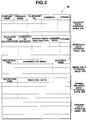
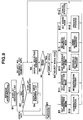
- Fig. 3 is a diagram showing a memory map of the RAM 29 of Fig. 2.
- the RAM 29 has an address data storage area 29a, a schedule data storage area 29b, a memo data storage area 29c, a normal message data storage area 29d, and an original data storage area 29e, so that it can store information input from the decoder 23, etc. for each information type, as shown in Fig. 3.
- the individual data storage areas are divided as follows.
- the address data storage area 29a is divided into areas for storing company name, person's name, telephone number, address or belonging department, and other arbitrary data.
- the schedule data storage area 29b is also divided into areas for storing schedule time information, contents of the schedule, appointment destination, sender's (transmitter's) name, and other arbitrary data.
- the memo data storage area 29c is also divided into areas for storing reception time, contents of a memo, and sender's name.
- the normal message data storage area 29d is also divided into areas for storing reception time, and received data.
- the original data storage area 29e is not divided into fixed areas, but can be divided into arbitrary areas by a user in accordance with data to be stored.
- the display section 32 is the display 6 constituted of a dot matrix type liquid crystal display unit or the like.
- the CPU 28 incorporates a ROM where various control programs are stored, a timer, input registers, etc. Based on the control programs stored in the ROM, the CPU 28 controls the individual circuit sections and execute various processes, such as a reception process, address mode process, and a schedule mode process, which will be described later. Beside the control programs, character data which are to be displayed on a menu display to be described later are also stored in the ROM.
- the information managing apparatus of this embodiment has the connector for a communication cable and the antenna for receiving radio-transmitted signals as well as a plurality of data entry keys as information input means, so that this apparatus can receive information from an external device via the communication cable or a radio communication system, e.g., radio paging system.
- a radio communication system e.g., radio paging system.
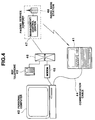
- Fig. 4 is a view showing a system arrangement in the case where information is input from an external device via the communication cable and radio paging system to the information managing apparatus of the present invention.
- reference numeral 41 denotes the information managing apparatus of the present invention
- 42 a personal computer which can be used as an external device for inputting information
- 43 a key telephone which also can be used as an external device for inputting information. Since the information managing apparatus 41 has the connector 5 (25) for a communication cable, the apparatus 41 can be connected via a communication cable 44 to the personal computer 42. Accordingly, various types of data prepared and stored in the personal computer 42, such as address data, schedule data and document data, can be stored directly in the RAM 29 of the information managing apparatus 41.
- the personal computer 42 when connected via a modem 45 to a PSTN (Public Switched Telephone Network) 46, can input information to the RAM 29 of the information managing apparatus 41 via a radio base station 48 of a paging service company. More specifically, when a call number assigned to the information managing apparatus 41 and information to be transmitted are transmitted via the PSTN 46 to a management control center 47 in the paging service company, the radio base station 48 transmits out an ID (Identification) code assigned to the information managing apparatus 41 and transmitted information, which will be received by the information managing apparatus 41. In the case of the key telephone 43, likewise, when the call number assigned to the information managing apparatus 41 and information to be transmitted are sent via the PSTN 46 to the management control center 47, this information can be input to the information managing apparatus 41.
- PSTN Public Switched Telephone Network
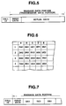
- Fig. 5 is a diagram showing a data structure of a transmission signal to be transmitted from the radio base station 48 of Fig. 4.
- the transmission signal has the ID code of a paging receiver to be called, followed by a message data portion, i.e., transmission data portion to be transmitted to the paging receiver.
- the message data portion is the data which a sender has sent to the management control center 47 in the paging service company.
- data to be transmitted is address data, schedule data or memo data
- the sender adds index data indicating the type of information, before the actual data to be transmitted, and transmits the actual data with an item name or item separator inserted for each item data so that data for each item, described earlier with reference to Fig. 3, can be properly recognized by the receiver.
- Fig. 6 is a diagram showing an example of an original data format.
- the information managing apparatus 41 can use a combination of information input via the communication cable and information input via the radio paging system. For instance, when data to be registered in the information managing apparatus 41 is a document type data as shown in Fig. 6, document format data, or document format data and each item data may be transmitted in advance via the communication cable to the information managing apparatus 41 from the personal computer 42 to be registered in this apparatus 41. As a result, only newly registered data or altered data can be transmitted via the radio paging system to the apparatus 41.
- Fig. 7 is a diagram showing a data structure of a transmission signal in the case where only altered data portions in the table in Fig. 6 are transmitted.
- the index data portion in the message data portion following the call ID includes a code which indicates that the information to be sent is original data.
- the actual data portion in the message data portion contains only the altered data (DA1, DC2, DE4) in the table together with data which indicates the altered sections.
- Fig. 8 is a flowchart for explaining a reception process performed in the apparatus 41.
- the reception process which will be performed when this apparatus 41 receives a call signal destined to own apparatus 41 from the radio base station 48 of the paging service company will be described below referring to the flowchart shown in Fig. 8.
- the decoder 23 of Fig. 2 detects that the call signal received by the antenna 21 and demodulated by the radio frequency receiving section 22 is destined to own apparatus 41, the decoder 23 outputs a call detection signal to the CPU 28. Upon reception of the call detection signal, the CPU 28 starts the reception process.
- step A1 Data which has been received and decoded by the decoder 23 is fetched by the CPU 28 (step A1), and then the type of the received data is discriminated (step A2).
- the data type is determined as one of address data, schedule data, memo data, normal message data and original data, based on the index data following the call ID in the transmitted data shown in Fig. 5. If the determined type of the data is address data (step A3), data of individual items are stored in the address data storage area 29a in the RAM 29 in Fig. 3 (step A8). If the determined data type is schedule data (step A4), data of individual items are likewise stored in the schedule data storage area 29b in the RAM 29 (step A9).
- the data type is memo data (step A5)
- the received data of the individual items and the reception time i.e., the current time counted by the time counting circuit 37 are stored in the memo data storage area 29c in the RAM 29 (step A10).
- the data type is normal data with a non-fixed type data format or data that has no filed data added (step A6)
- the received data and the reception time are stored in the normal message data storage area 29d in the RAM 2-9 (step A11).
- the data type is original data (step A7), the original data in the original data storage area 29e in the RAM 29 is rewritten in accordance with the instruction of that original data before terminating this process (step A12).
- a reception informing process will be started (step A13). More specifically, the reception informing process consists of processes of reading the character pattern of each of characters constituting the received data from the CG 30 of Fig. 2; setting the character patterns in the display buffer 31 to thereby display the received data on the display section 32 (the liquid crystal display 6 in Fig. 1); outputting an informing signal via the amplifier 33 to the loudspeaker 34 to be sounded; and/or outputting a lighting signal via the amplifier 35 to the LED 36 to light it. Then, it is determined if a key input from any of the various keys of Fig. 1 has been entered within a predetermined period of time (steps A14 and A15).
- step A16 If no key input has been entered, the reception informing process such as data display is stopped before terminating this process (step A16). On the other hand, if a key input has been entered, it is then determined if that key input is an input by the reset key 14 (step A17). If it is the reset key 14 operated, the reception informing process such as data display will be stopped immediately before terminating this process (step A16). If the key input is not the reset key input in the step 17, a process according to other key input will be initiated (step A18). As the information managing apparatus of the present invention has the telephone key 7, schedule key 8, memo key 9, message key 10 and original key 11 as mode designating keys, as shown in Fig. 1, it is possible to select a processing mode by operating any of those mode keys. As a result, various types of processes, such as registering and retrieving for the received data (management information) stored in the RAM 29 is specified. The operations in the individual modes will be described below.
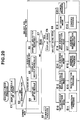
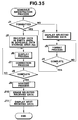
- the address mode process will be described referring to the flowchart given in Fig. 9.
- a telephone key input signal is input to the CPU 28 from the key input section 27 and the address mode process will be initiated.
- main item data company name and person's name
- address data is read out from the address data storage area 29a in the RAM 29.
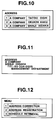
- a list of addresses shown in Fig. 10 is displayed on the display section 32 (step B1). It is then discriminated whether the subsequent input key is an input by the display change key 12, the select number designate key (numeric key) or some other key (step B2). If the key input is that of some other key, a process designated by that input key will be initiated (step B3).
- step B4 If the key input is an input by the display change key 12, the next list of addresses will be displayed (step B4). The process then returns to the input key discrimination in step B2. If the input key is a select number designate key, i.e., a numeric key corresponding to the selection number displayed on the left end of the address list display on the screen of Fig. 10, the address data of the selected number will be displayed on the display section 32, as shown in Fig. 11 (step B5). Fig. 11 shows an example of display when the address data of the select number designate key "3" is selected. Then, it is determined whether or not the menu key 16 is depressed (step B6).
- a select number designate key i.e., a numeric key corresponding to the selection number displayed on the left end of the address list display on the screen of Fig. 10
- the address data of the selected number will be displayed on the display section 32, as shown in Fig. 11 (step B5).
- Fig. 11 shows an example of display when the address
- step B3 If a key other than the menu key 16 is depressed, a process designated by that key input will be initiated (step B3).
- a menu key 16 when the menu key 16 is depressed, a menu will be displayed on the display section 32, as shown in Fig. 12, to request a menu selection (step B7).
- the menu selection in step B8 is executed by designating the desired selection number displayed on the left end on the menu display screen in Fig. 12, as done in the selection of the address data.
- this address correction mode is set (step B9) to permit correction of the address data selected in step B5.
- the process returns to the display of the selected address in step B5 (step B10).
- the address registration mode is set in the menu selection in step B8 (step B11)
- a menu for individual items of Fig. 13 used for address registration process will be displayed on the display section 32 to request the registration of the address data.
- the address data are company name, person's name, telephone number, address and other data.
- the address data input by the operation of the data entry keys 4 is stored in an empty area in the address data storage area 29a in the RAM 29.
- step B12 The process then returns to the display of the selected address in step B5 (step B12). If the schedule retrieval mode is set in the menu selection in step B8 (step B13), a process for the schedule retrieval mode which will be described in detail later is executed. Thereafter the process returns to the display of the selected address in step B5 (step B14). If the memo retrieval mode is set in the menu selection in step B8 (step B15), a process for the memo retrieval mode which will be described in detail later is executed. The process then returns to the display of the selected address in step B5 (step B16).
- step B17 If the erase mode is set by the menu selection in step B8 (step B17), erasure of the address data of the selected number in the address data storage area 29a in the RAM 29 is executed before the process returns to the display of the selected address in step B5 (step B18). If the cancel process is specified in the menu selection in step B8 (step B18), the menu display is cancelled. The process returns to the display of the selected address in step B5 (step B19).
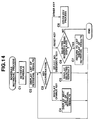
- step C1 a schedule in which the appointment destination (appointed person's name) in the schedule data stored in the schedule data storage area 29b in the RAM 29 in Fig. 3 coincides with a person's name in the currently selected address data, i.e., the address data selected in step B5 in the address mode process in Fig. 9 is retrieved (step C1).
- a list of the retrieval results will be displayed on the display section 32 as shown in Fig. 15 (step C2). It is then discriminated whether the input key is the display change key 12, the select number designate key (numeric key), or the reset key 14 (step C3).
- step C4 the next list of the retrieval results will be displayed (step C4).
- step C3 If it is the display change key 12, the next list of the retrieval results will be displayed (step C4).
- the process then returns to the input key discrimination in step C3.
- step C5 If the select number designate key is used as the input key, a schedule for that selected number as shown in Fig. 16 will be displayed on the display section 32 (step C5).
- step C5 If the input key is the reset key 14, it is then determined whether or not the selected schedule is being displayed on the screen (step C6). Unless this schedule is being displayed on the screen, the process will be terminated without returning to step B5 in the address mode process of in Fig. 9. If this schedule is being displayed, the process returns to the display of a list of the retrieval results (step C7).
- step C8 If some other key is used as the input key, a process designated by that key input will be initiated (step C8).
- step D1 a memo in which the sender's name in the memo data stored in the memo data storage area 29c in the RAM 29 matches with a person's name in the currently selected address data, i.e., the address data selected in step B5 in the address mode process in Fig. 9 is retrieved (step D1).
- a list of retrieval results as shown in Fig. 18 will be displayed on the display section 32 (step D2). It is then discriminated whether the input key is the display change key 12, the select number designate key (numeric key), or the reset key 14 (step D3).
- step D4 the next list of retrieval results will be displayed (step D4) before the process returns to the input key discrimination in step D3.
- the input key is the select number designate key, a schedule for that selected number, as shown in Fig. 19, will be displayed on the display section 32 (step D5). The process then returns to the input key discrimination in step D3.
- the input key is the reset key 14, it is then determined whether or not the selected schedule is being displayed on the screen (step D6). Unless this schedule is displayed, this process will be terminated without returning to step B5 in the address mode process of Fig. 9.
- step D7 the process returns to the display of a list of the retrieval results (step D7) and then returns to the input key discrimination in step D3. If some other key is used as the input key, a process designated by that input key will be initiated (step D8).
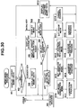
- schedule mode process will be described next referring to the flowchart given in Fig. 20.
- a schedule key input signal is input to the CPU 28 from the key input section 27 and the schedule mode process will be initiated.
- schedule data is read out from the schedule data storage area 29b in the RAM 29.
- a schedule of today, as shown in Fig. 21, is displayed on the display section 32 (step E1). It is then discriminated whether the subsequent input key is the cursor keys 17, the display change key 12, the select number designate key (numeric key) or some other key (step E2). If the input key is some other key, a process designated by that input key will be initiated (step E3).
- step E4 If the input key is one of the cursor keys 17, the next schedule is displayed (step E4). The process then returns to the input key discrimination in step E2. If the input key is the display change key 12, a weekly schedule, as shown in Fig. 22, will be displayed before the process returns to the input key discrimination in step E2 (step E5). If the input key is the select number designate key, the schedule data of the selected number will be displayed on the display section 32 (step E6). The display of the schedule data may be such as shown in Fig. 16. Then, it is determined whether or not the menu key 16 is depressed (step E7). If a key other than the menu key 16 is depressed, a process designated by that key input will be initiated (step E3).
- a menu will be displayed on the display section 32, as shown in Fig. 23, to be selected by the user (steps E8 and E9).
- Schedule correction mode, schedule registration mode, address retrieval mode, address registration mode and erase mode can be selected by the user in the step E9 of Fig. 20.
- step E10 If the schedule correction mode is set in the menu selection step in step E9 (step E10), the schedule data of the selected number stored in the RAM 29 is rewritten by the operation of the data entry keys 4 (step E11) and the process returns to the display of the selected schedule in step E6.
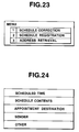
- step E12 If the schedule registration mode is set in the menu selection step in step E9 (step E12), a menu for individual items of Fig. 24 used for schedule registration process will be displayed on the display section 32 to request the registration of the schedule data for the user.
- the schedule data are scheduled time, schedule contents, appointment destination, sender and other.
- the schedule data input by the operation of the data entry keys 4 is stored in an empty area in the schedule data storage area 29b in the RAM 29 (step E13).
- step E15 a process for the address retrieval mode, which will be described in detail later, is executed (step E15). The process then returns to the display of the selected address in step E6.
- step E16 a process for the address registration mode, which will also be described in detail later, is executed (step E17) before the process returns to the display of the selected schedule in step E6.
- step E18 erasure of the address data of the selected number in the schedule data storage area 29b in the RAM 29 is executed (step E19). The process then returns to the display of the selected schedule in step E6. If the cancel process is designated in the menu selection in step E9, the menu display is cancelled. Then the process returns to the display of the selected schedule in step E6 (step E20).
- step F1 an address data in which the company name and/or a person's name in the address data stored in the address data storage area 29a in the RAM 29 matches with the appointment destination in the currently selected schedule data is retrieved (step F1).
- a list of retrieval results will be displayed on the display section 32, as shown in Fig. 27, when there are a few associated items (step F2).
- step F3 it is determined whether the input key is the display change key 12, the select number designate key (numeric key), or the reset key 14 (step F3). If it is the display change key 12, the next list of retrieval results will be displayed (step F4).
- step F5 If the input key is the select number designate key, the address designated by the selected number will be displayed on the display section 32 (step F5) before the process returns to the input key discrimination in step F3.
- the display of the address in step F5 may be as shown in Fig. 11.
- step F6 If the input key is the reset key 14, it is then determined whether or not the selected address is being displayed on the screen (step F6). Unless the selected address is being displayed on the screen, the process will be terminated without returning to the step E6 in the schedule mode process of Fig. 20. If the selected address is being displayed on the screen, the process proceeds to the display of a list of retrieval results (step F7). The process then returns to the input key discrimination in step F3. If the input key is some other key, a process designated by the input key will be initiated (step F8).
- step G1 the appointment destination data in the selected schedule data is read out and is registered in an empty area in the address data storage area 29a in the RAM 29 (step G1).
- step G2 A displaying process of the registered address data or the appointment destination data is performed (step G2).
- step G3 Addition and correction operations of each item data in the address data is then performed (step G3). It is then determined if the correction has been completed (step G4). If the correction has not been completed yet, the process returns to the step G2 to repeat the correction operation. While, if the correction has been completed, the address data stored in the address data storage area 29a is sorted in alphabetical order before terminating this process (step G5).
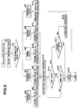
- Fig. 29 shows the relationship between the selected schedule data targeted for the address registration and the registered address data on the display screen.
- the display screen on the left side in Fig. 29 shows the selected schedule data in step E6 in Fig. 20.
- the center display screen shows the registered address data when the process advances to step G2 from step G1 in Fig. 28.
- the display screen on the right side in Fig. 29 shows the registered address data in step G2 after addition of item data has been performed in step G3 in Fig. 28.
- a memo key input signal is input to the CPU 28 from the key input section 27 and the memo mode process will be initiated.
- the latest memo data is read out from the memo data storage area 29c in the RAM 29.
- the latest memo data is displayed on the display section 32 (step H1). This display of the latest memo data may be as shown in Fig. 19. It is then discriminated whether the subsequent input key is the cursor keys 17, the display change key 12, the menu key 16 or some other key (step H2). If the input key is some other key, a process designated by the input key will be initiated (step H3).
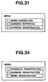
- step H4 the next memo data is displayed (step H4). If the input key is the display change key 12, a batch display of the memo data of today is executed (step H5). It is determined if the subsequent input key is the select number designate key (numeric key) (step H6). If it is not the select number designate key, a process according to that input key is initiated (step H3). If the input key is the select number designate key, the memo data of the selected number will be displayed (step H7) before the process returns to the input key discrimination in step H2. If the input key is discriminated as the menu key 16 in the input key discrimination in step H2, a menu will be displayed, as shown in Fig. 31, to be selected by the user (steps H8 and H9). In the step H9 of Fig. 30, memo correction mode, address retrieval mode, address registration mode and erase mode can be selected by the user.
- step H10 If the memo correction mode is set in the menu selection in step H9 (step H10), the memo data of the selected number in the RAM 29 is rewritten by the operation of the data entry keys 4 (step H11). Previously selected memo data is displayed on the display screen of the display section 32 (step H12) before the process returns to the input key discrimination in step H2.
- step H13 When the address retrieval mode process is set in the memo selection in step H9 (step H13), the address data which contains a name that matches with the transmitter of the memory data is retrieved (step H14). A list of retrieval results becomes the same as the one shown in Fig. 27. If the address registration mode is set in the menu selection in step H9 (step H15), a process which is nearly the same as the address registration mode process shown in Fig.
- Previously selected memo data is also displayed on the display screen of the display section 32 (step H12) before the process returns to the input key discrimination in step H2.
- sender's name data in the memo data is registered as name data in an empty area in the address data storage area 29a in the RAM 29.
- erase mode is set in the menu selection in step H9 (step H17)
- erasure of the memo data of the selected number in the memo data storage area 29c in the RAM 29 is performed (step H18).
- Previously selected memo data is also displayed on the display screen of the display section 32 (step H12) and then the process returns to the input key discrimination in step H2.
- the cancel process is designated in the menu selection in step H9, the menu display is cancelled (step H19).
- Previously selected memo data is also displayed on the display screen of the display section 32 (step H12). The process then returns to the input key discrimination in step H2.
- Fig. 32 shows the relationship between the selected memo data targeted for the address registration and the registered address data on a display screen.
- the display screen on the left side in Fig. 32 is a screen of the selected memo data which has been displayed on the display section 32 before the depression of the menu key 16 in the memo mode process in Fig. 30.
- the center display screen shows the registered address data when the process enters the address registration mode.
- the display screen on the right side shows the registered address data after addition of item data has been performed.
- step I1 the latest received data is read out from the normal message data storage area 29d in the RAM 29 and is displayed on the display section 32. It is then discrimination whether the subsequent input key is the display change key 12, the menu key 16 or some other key (step I2). If the input key is some other key, a process designated by that other key input will initiated (step I3). If the input key is display change key 12, the next received data will be displayed on the display screen of the display section 32 (step I4). Thus the process returns to the input key discrimination in step I2. If the input key is the menu key 16, a menu will be displayed, as shown in Fig. 34, to be selected by the user (steps I5 and I6).
- step I7 If the schedule registration mode is set in the menu selection in step I6 (step I7), the process advances to the schedule registration process to execute the process of the flowchart which is described later (step I8). The process then returns to the input key discrimination in step I2.
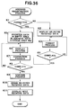
- step I9 the address registration mode process is initiated.
- step I10 The process of the flowchart in Fig. 36 is executed (step I10) before returning to the input key discrimination in step I2.
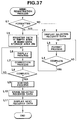
- the memo registration mode is set by the menu selection in step I6 (step I11)
- the memo registration mode process is initiated and the process of the flowchart in Fig. 37 is executed (step I12). The process returns to the input key discrimination in step I2.
- step I13 If the erase mode in set by the menu selection in step I6 (step I13), the selected received data stored in the normal message data storage area 29d is erased (step I14). The process returns to the input key discrimination in step I2.
- the cancel process is selected in the menu selection in step I6, the menu display is cancelled (step I5) before the process returns to the input key discrimination in step I2 of Fig. 33.
- step J1 it is determined if the received data is formatted as schedule data (step J1). That is, if the item data such as the scheduled time information, schedule contents and appointment destination, are separated by item separating codes or the like. It is determined if the received data is schedule data where the transmitter has forgotten to add the information identification codes in the index data portion of the transmission data format shown in Fig. 5 when the data is transmitted. If the selected received data has formatted as schedule data, the process advances to step J5. Otherwise, the process goes to step J2 to display the selected received data on the display section 32, requesting formatting process of the schedule data (step J3).
- step J3 In the formatting process in step J3, addition or correction of necessary item data, insertion of item separation codes or the like is performed by the operation of the data entry keys 4.
- step J4 the process also advances to step J5.
- the received data which is determined to be already formatted as schedule data or the received data formatted to be schedule data in step J3 is stored in an empty area in the schedule data storage area 29b in the RAM 29 (step J5).
- the registered schedule data is displayed on the display section 32 to request for further correction (step J6).
- step J7 and J8 the schedule data in the schedule data storage area 29b is sorted in the order of the date and time (step J9).
- step J9 the selected received data in the normal message data storage area 29d is erased (step J10).
- the next received data is displayed (step J11) before the process is ended.
- the process then returns to the normal message mode process in Fig. 33.
- step K1 it is determined if the selected received data is formatted as address data (step K1). That is if the received data is address data where the information identification codes has not been added in the index data portion of the transmission data format shown in Fig. 5 by the sender when the data is transmitted. If the selected received data is data having formatted as address data, the process advances to step K5. Otherwise, the process goes to step K2 to display the selected received data on the display section 32, requesting formatting process of the address data.
- step K3 In the formatting process in step K3, addition or correction of necessary item data, insertion of item separation codes or the like is performed by the operation of the data entry keys 4, and when the formatting is complete (step K4), the process also proceeds to step K5.
- the received data which has been determined to be already formatted as address data or the received data formatted to be address data in step K3 is stored in an empty area in the address data storage area 29a in the RAM 29 (step K5).
- the registered address data is displayed on the display section 32 to request for further correction (step K6).
- step K7 and K8 When the correction of the registered address data is completed (steps K7 and K8), the address data stored in the address data storage area 29a is sorted in alphabetical order of the names (step K9).
- the selected received data in the normal message data storage area 29d is erased (step K10).
- the next received data is displayed (step K11) before terminating this process.
- the process returns to the normal message mode process in Fig. 33.
- step L1 it is determined if the selected received data has been formatted as memo data (step L1). If the received data is memo data where the information identification codes has not been added in the index data portion of the transmission data format shown in Fig. 5 by the sender when the data is transmitted. If the selected received data is data having formatted as memo data, the process advances to step L5. Otherwise, the process goes to step L2 to display the selected received data on the display section 32, requesting formatting process of the memo data (step L3). In the formatting process in step L3, addition or correction of necessary item data, insertion of item separation codes or the like is performed by the operation of the data entry keys 4.
- step L4 When the formatting process is complete (step L4), the process also advances to step L5.
- the received data which has been determined to be already formatted as memo data or the received data formatted to be memo data in step L3 is stored in an empty area in the memo data storage area 29c in the RAM 29 (step L5).
- the registered memo data is displayed on the display section 32 to request for further correction (step L6).
- the memo data stored in the memo data storage area 29c is sorted in the order of the reception date and time (step L9).
- step L10 the selected received data in the normal message data storage area 29d is erased (step L10).
- the next received data is displayed (step L11) before terminating this process.
- the process returns to the normal message mode process in Fig. 33.
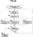
- the original data mode process will be described referring to the flowchart in Fig. 38.
- an original key input signal is input to the CPU 28 from the key input section 27 and the original data mode process is initiated.
- a list of original data formats set by the user is displayed on the display section 32, requesting selection of a file to be processed (step M1).
- the data of the selected file is read out from the original data storage area 29e in the RAM 29 and is displayed on the display section 32 (steps M3(1) to M3(N)).
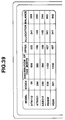
- An example of the display of the file data is shown in Fig. 39.
- step M4 it is determined whether or not the operated key is the display change key 12 (step M4). If the operated key is the display change key 12, the process returns to the display of the file list in step M1. On the other hand, if it is some other key, a process designated by that other key will be executed (step M5).
Abstract
Description
- The present invention relates to an information managing apparatus for managing various types of information placed in different categories in accordance with their categories and, more particularly, to an information managing apparatus which can store and display various types of information input by operating keys and the like in units of types of information.
- Various information managing apparatuses are known, among which are electronic notebook and portable computers. An electronic notebook is used widely as a personal apparatus for managing data items, for example. The electronic notebook has address note (telephone directory) function for registering and retrieving address information, schedule function for registering and retrieving schedule information, calendar function for registering and retrieving calendar information, and memo function for registering and retrieving memo information, and has also function as a calculator. The electronic notebook has a keyboard comprising many keys, some of which are assigned to the address (telephone number) registering and retrieving function, schedule registering and retrieving function, the calendar registering and retrieving function, memo registering and retrieving function, the calculator function, and the like. To register or retrieve an data item of any type into and from the memory, an user operates the key assigned to the corresponding function, thereby selecting that function, and then operates some other keys.
- Some types of the electronic notebook and portable computers can be connected by a communication cable to an office computer or a home-use computer such as a personal computer, so that they may access to the information stored in a large-capacity memory incorporated in the office computer or home-use computer. Other types can be connected to a paging receiver, so that information radio-transmitted from an information source may be input to them through the paging receiver. U.S. Patent 5,043,721, for example, discloses a portable computer with a plug-in type accessory port and a portable computer with a communication interface port such as an RS232 port. The conventional information managing apparatuses described above can store and display addresses, schedules, memos, and the like.
- However, in the conventional information managing apparatuses, any type of data cannot be registered or displayed unless the corresponding function is being selected. More specifically, addresses can be neither registered nor retrieved unless the address registering and retrieving function is selected. Schedule data can be neither registered nor retrieved unless the schedule registering and retrieving function is selected. Memo information can be neither registered nor retrieved unless the memo registering and retrieving function is selected. Therefore, to retrieve and check an data item related to another which is being retrieved, the user needs to change the function. This is rather cumbersome for the user to do so.
- Of course, such a related data item can be stored in not only the proper storage area of the memory, but also the same storage area as the data item being retrieved from the memory. Then, both data items may be simultaneously retrieved and displayed. In this case, however, the same data item is stored in a plurality of storage areas, inevitably reducing the memory-use efficiency.
- A data item such as a person's name needs to be stored along with not only address information, but also schedule information and memos information. Hence, the data item must be stored in two or more storage areas of the memory. Here lies a problem. Since any data item cannot be registered unless the corresponding function is selected, the user must repeat almost the same input operation as many times as the independent storage areas into which the data item is stored. This is also a troublesome work for the user to do so.
- Accordingly, the object of the present invention is to provide an information managing apparatus which can register and retrieve related information in plural and different function modes, and has storage areas assigned to various categories of data, and which can simultaneously register and retrieve an data item into and from different storage areas of the memory.
- According to an aspect of the present invention, there is provided an information managing apparatus comprising: means for inputting various types of information, each consisting of a plurality of data items; a plurality of storing means, each having storage areas in which said plurality of data items of one type of information are stored and for independently storing said data items of one type of information which is input from said inputting means; first designating means for designating one of said storing means so as to display selectively information stored in the designated one of said storing means; means for displaying said information stored in that one of said storing means designated by said first designating means; second designating means for designating a mode in which information is to be registered into and retrieved from another of said storing means while said displaying means is displaying said information designated by said first designating means; and means for executing registration of a specified data item of information which is being displayed into said another of said storing means and retrieval of said specified data item of information from said another of said storing means in accordance with said mode designated by said second designated means.
- According to another aspect of the present invention, there is provided an information managing apparatus comprising: means for inputting function mode information of serious formats used for a plurality of function modes, each function mode information consisting of a plurality of data items; a plurality of storing means, each being provided independently and correspondingly to one of said function modes and having storage areas in which said plurality of data items of information of one format are stored, and for storing information input from said inputting means; means for displaying selectively said function mode information of various formats; display mode selecting means for selecting one of said function modes to selectively display information stored in one of said storing means which corresponds to selected one function mode on said displaying means; process mode selecting means for selecting another of said function modes to process information stored in another of said storing means which corresponds to selected another function mode; and means for enabling said display mode selecting means and said process mode selecting means to independently operate and for processing information of said another of said function modes while information of said one of said function modes is being displayed.
- This invention can be more fully understood from the following detailed description when taken in conjunction with the accompanying drawings, in which:
- Fig. 1 is a view illustrating an external appearance of an information managing apparatus according to the present invention;
- Fig. 2 is a block diagram illustrating the circuit structure of the information managing apparatus shown in Fig. 1;
- Fig. 3 is a diagram showing a memory map of the RAM shown in Fig. 2;
- Fig. 4 is a view showing a system arrangement in which information is input from an external device to the information managing apparatus of the present invention;
- Fig. 5 is a diagram showing a data structure of a signal transmitted to the information managing apparatus from a radio base station of Fig. 4;
- Fig. 6 is a diagram showing an example of an original data format;
- Fig. 7 is a diagram showing a data structure of a signal transmitted from a radio base station when transmitted data is the original data;
- Fig. 8 is a flowchart for explaining a reception process performed in the apparatus in response to a call signal transmitted from the radio base station;
- Fig. 9 is a flowchart for explaining an address mode process;
- Fig. 10 is a diagram showing an example of address list displayed in the address mode process of Fig. 9;
- Fig. 11 is a diagram showing an example of address data displayed in the address mode process of Fig. 9;
- Fig. 12 is a diagram illustrating an example of selection menu displayed in the address mode process of Fig. 9;
- Fig. 13 is a diagram showing an example of a guidance display displayed in an address registration process used in the address mode process of Fig. 9;
- Fig. 14 is a flowchart for explaining schedule retrieval mode process performed in the address mode process of Fig. 9;
- Fig. 15 is a diagram showing an example of displayed results of schedule retrieval;
- Fig. 16 is a diagram showing an example of displayed schedule data;
- Fig. 17 is a flowchart for explaining a memo retrieval mode process performed in the address mode process of Fig. 9;
- Fig. 18 is a diagram showing an example of displayed results of memo retrieval;
- Fig. 19 is a diagram showing an example of displayed memo data;
- Fig. 20 is a flowchart for explaining a schedule mode process;
- Fig. 21 is a diagram illustrating an example of a today schedule displayed in the schedule mode process of Fig. 20;
- Fig. 22 is a diagram showing an example of a weekly schedule displayed in the schedule mode process of Fig. 20;
- Fig. 23 is a diagram showing an example of a selection menu displayed in the schedule mode process of Fig. 20;
- Fig. 24 is a diagram illustrating an example of a guidance display displayed in a schedule registration process used in the schedule mode process of Fig. 20;
- Fig. 25 is a flowchart for explaining an address retrieval mode process performed in the schedule mode process of Fig. 20;
- Fig. 26 is a diagram showing an example of displayed results of an address retrieval of Fig. 25;
- Fig. 27 is a diagram showing another example of displayed results of address retrieval of Fig. 25;
- Fig. 28 is a flowchart for explaining an address registration mode process performed in the schedule mode process of Fig. 20;
- Fig. 29 is a view illustrating display screens which show a relationship between schedule data targeted for address registration and the address registration data;
- Fig. 30 is a flowchart for explaining a memo mode process;
- Fig. 31 is a diagram illustrating an example of a selection menu displayed in the memo mode process of Fig. 30;
- Fig. 32 is a view illustrating display screens which show a relationship between memo data targeted for address registration and the address registration data;
- Fig. 33 is a flowchart for explaining a normal message mode process;
- Fig. 34 is a diagram showing an example of a selection menu displayed in the normal message mode process of Fig. 33;
- Fig. 35 is a flowchart for explaining a schedule registration mode process performed in the normal message mode process of Fig. 33;
- Fig. 36 is a flowchart for explaining an address registration mode process performed in the normal message mode process of Fig. 33;
- Fig. 37 is a flowchart for explaining a memo registration mode process performed in the normal message mode process of Fig. 33;
- Fig. 38 is a flowchart for explaining an original data mode process; and
- Fig. 39 is a view showing an example of file data displayed in the original data mode process of Fig. 38.
- An embodiment of the present invention will now be described referring to the accompanying drawings.
- Fig. 1 is a view illustrating the external appearance of the information managing apparatus according to the present invention. The information managing apparatus according to the present invention is designed to allow various types of information to be input by an external devices via a communication cable or radio communication as well as data input keys provided on this apparatus. This apparatus is also provided with means for storing various types of input information, such as address information, schedule information and memo information, independently for each information type, and means for displaying them. In Fig. 1,
reference numeral 1 denotes a main body of the apparatus; 2, a cover of the main body; and 3, a hinge portion which rotatably supports thecover 2 on themain body 1. In other words, the information managing apparatus of this embodiment is designed so that themain body 1 and thecover 2 are foldable with respect to each other at thehinge portion 3. A plurality ofdata input keys 4, which include alphabetic keys, numeric keys and control keys, are provided on the top of themain body 1. Aconnector 5 for a communication cable is provided at one side of themain body 1. Although not shown, an antenna for receiving radio signals, essential electronic parts constituting an electronic circuit to be described later, a battery and so forth are incorporated in themain body 1. Provided at the front of thecover 2 are adisplay 6, atelephone key 7, aschedule key 8, amemo key 9, a message key 10, anoriginal key 11, adisplay change key 12, time/date key 13, areset key 14, an offkey 15, a menu (MENU/ON)key 16, andcursor moving keys 17. AnLED cover 18 is provided at one side edge portion of thecover 2. Thedisplay 6 displays various types of information consisting of characters, numerals, symbols and so forth, and is constituted of, for example, a dot matrix type of liquid crystal display unit. Thetelephone key 7 designates an address mode in which address data consisting of a person's name, a telephone number, etc. can be registered and retrieved. Theschedule key 8 designates a schedule mode in which schedule data can be registered and retrieved. Thememo key 9 designates a memo mode in which memo data can be registered and retrieved. The message key 10 designates a normal message mode in which message data can be retrieved. Theoriginal key 11 designates an original data mode in which original data can be registered and retrieved. Adisplay change key 12 serves to change display data while a process in each mode is being executed. The time/date key 13 designates a mode to display the current date and time. The reset key 14 stops reception indication or resets a sub mode in such a mode as the address mode. The off key 15 instructs the deactivation of the display function. The menu/onkey 16 instructs the activation of the display function or instructs menu display while the display function is enabled. Thecursor move keys 17 instruct the moving direction of the cursor displayed on thedisplay 6 or instruct a screen scroll. TheLED cover 18 serves to extract light of a reception indicating LED (light Emitting Diode) from the front, side and back of thecover 2. - Fig. 2 is a block diagram illustrating the circuit structure of the information managing apparatus shown in Fig. 1. The information managing apparatus of the present invention has, as information input means, paging signal reception means which includes an
antenna 21, a radiofrequency receiving section 22, adecoder 23 and an ID-ROM (Identification Read Only Memory) 24; communication means which includes aconnector 25 and acommunication interface 26; and akey input section 27 having a plurality of keys shown in Fig. 1. In addition, a RAM (Random Access Memory) 29 for storing information from those components, a character generator (CG) 30 having stored a plurality of character patterns, adisplay buffer 31 for temporarily storing a plurality of character patterns corresponding to information to be displayed on adisplay section 32, anamplifier 33 for driving aloudspeaker 34 for informing reception, anamplifier 35 for driving anLED 36 for informing reception, and atime counting circuit 37 for counting the current time are provided. Thedecoder 23, thecommunication interface 26, thekey input section 27, theRAM 29, theCG 30, thedisplay buffer 31, theamplifiers time counting circuit 37 are connected to the CPU (Central Processing Unit) 28. Theantenna 21 receives a call signal radio-transmitted from a radio base station such as a paging service company, and outputs the call signal to theradio receiver section 22. The radiofrequency receiving section 22 intermittently receives the call signal input from theantenna 21, demodulates the received signal and supplies the demodulated signal to thedecoder 23 under the control of thedecoder 23. Thedecoder 23 determines if the call number specified by the input call signal from the radiofrequency receiving section 22 matches with its own identification number registered in advance in the ID-ROM 24. If matching occurs, thedecoder 23 permits the radiofrequency receiving section 22 to continue the signal reception, and sends out a call detection signal to aCPU 28. Thedecoder 23 also outputs information, received following the call signal due to the resumed signal reception, to theCPU 28 in response to a request from theCPU 28. Theconnector 25 is theconnector 5 for a communication cable, and is connected to an external device via the communication cable. Thisconnector 25 is also connected via thecommunication interface 26 to theCPU 28. Thecommunication interface 26 outputs the information, input via the communication cable andconnector 25 from an external device, to theCPU 28, and outputs the information from theCPU 28 to the external device via the communication cable andconnector 25. When any of the keys shown in Fig. 1 is operated, thekey input section 27 outputs a key signal corresponding to the operated key to theCPU 28. - Fig. 3 is a diagram showing a memory map of the
RAM 29 of Fig. 2. TheRAM 29 has an addressdata storage area 29a, a scheduledata storage area 29b, a memodata storage area 29c, a normal messagedata storage area 29d, and an originaldata storage area 29e, so that it can store information input from thedecoder 23, etc. for each information type, as shown in Fig. 3. The individual data storage areas are divided as follows. The addressdata storage area 29a is divided into areas for storing company name, person's name, telephone number, address or belonging department, and other arbitrary data. The scheduledata storage area 29b is also divided into areas for storing schedule time information, contents of the schedule, appointment destination, sender's (transmitter's) name, and other arbitrary data. The memodata storage area 29c is also divided into areas for storing reception time, contents of a memo, and sender's name. The normal messagedata storage area 29d is also divided into areas for storing reception time, and received data. The originaldata storage area 29e is not divided into fixed areas, but can be divided into arbitrary areas by a user in accordance with data to be stored. Thedisplay section 32 is thedisplay 6 constituted of a dot matrix type liquid crystal display unit or the like. TheCPU 28 incorporates a ROM where various control programs are stored, a timer, input registers, etc. Based on the control programs stored in the ROM, theCPU 28 controls the individual circuit sections and execute various processes, such as a reception process, address mode process, and a schedule mode process, which will be described later. Beside the control programs, character data which are to be displayed on a menu display to be described later are also stored in the ROM. - A description will now be given of the operation of the information managing apparatus of the present invention. As described earlier, the information managing apparatus of this embodiment has the connector for a communication cable and the antenna for receiving radio-transmitted signals as well as a plurality of data entry keys as information input means, so that this apparatus can receive information from an external device via the communication cable or a radio communication system, e.g., radio paging system.
- Fig. 4 is a view showing a system arrangement in the case where information is input from an external device via the communication cable and radio paging system to the information managing apparatus of the present invention. In Fig. 4,
reference numeral 41 denotes the information managing apparatus of the present invention; 42, a personal computer which can be used as an external device for inputting information; and 43, a key telephone which also can be used as an external device for inputting information. Since theinformation managing apparatus 41 has the connector 5 (25) for a communication cable, theapparatus 41 can be connected via acommunication cable 44 to thepersonal computer 42. Accordingly, various types of data prepared and stored in thepersonal computer 42, such as address data, schedule data and document data, can be stored directly in theRAM 29 of theinformation managing apparatus 41. Thepersonal computer 42, when connected via amodem 45 to a PSTN (Public Switched Telephone Network) 46, can input information to theRAM 29 of theinformation managing apparatus 41 via aradio base station 48 of a paging service company. More specifically, when a call number assigned to theinformation managing apparatus 41 and information to be transmitted are transmitted via thePSTN 46 to amanagement control center 47 in the paging service company, theradio base station 48 transmits out an ID (Identification) code assigned to theinformation managing apparatus 41 and transmitted information, which will be received by theinformation managing apparatus 41. In the case of thekey telephone 43, likewise, when the call number assigned to theinformation managing apparatus 41 and information to be transmitted are sent via thePSTN 46 to themanagement control center 47, this information can be input to theinformation managing apparatus 41. - Fig. 5 is a diagram showing a data structure of a transmission signal to be transmitted from the
radio base station 48 of Fig. 4. The transmission signal has the ID code of a paging receiver to be called, followed by a message data portion, i.e., transmission data portion to be transmitted to the paging receiver. The message data portion is the data which a sender has sent to themanagement control center 47 in the paging service company. When data to be transmitted is address data, schedule data or memo data, the sender adds index data indicating the type of information, before the actual data to be transmitted, and transmits the actual data with an item name or item separator inserted for each item data so that data for each item, described earlier with reference to Fig. 3, can be properly recognized by the receiver. - Fig. 6 is a diagram showing an example of an original data format. The
information managing apparatus 41 can use a combination of information input via the communication cable and information input via the radio paging system. For instance, when data to be registered in theinformation managing apparatus 41 is a document type data as shown in Fig. 6, document format data, or document format data and each item data may be transmitted in advance via the communication cable to theinformation managing apparatus 41 from thepersonal computer 42 to be registered in thisapparatus 41. As a result, only newly registered data or altered data can be transmitted via the radio paging system to theapparatus 41. - Fig. 7 is a diagram showing a data structure of a transmission signal in the case where only altered data portions in the table in Fig. 6 are transmitted. In this case, the index data portion in the message data portion following the call ID includes a code which indicates that the information to be sent is original data. The actual data portion in the message data portion contains only the altered data (DA1, DC2, DE4) in the table together with data which indicates the altered sections.
- Fig. 8 is a flowchart for explaining a reception process performed in the
apparatus 41. The reception process which will be performed when thisapparatus 41 receives a call signal destined to ownapparatus 41 from theradio base station 48 of the paging service company will be described below referring to the flowchart shown in Fig. 8. When thedecoder 23 of Fig. 2 detects that the call signal received by theantenna 21 and demodulated by the radiofrequency receiving section 22 is destined to ownapparatus 41, thedecoder 23 outputs a call detection signal to theCPU 28. Upon reception of the call detection signal, theCPU 28 starts the reception process. Data which has been received and decoded by thedecoder 23 is fetched by the CPU 28 (step A1), and then the type of the received data is discriminated (step A2). In other words, the data type is determined as one of address data, schedule data, memo data, normal message data and original data, based on the index data following the call ID in the transmitted data shown in Fig. 5. If the determined type of the data is address data (step A3), data of individual items are stored in the addressdata storage area 29a in theRAM 29 in Fig. 3 (step A8). If the determined data type is schedule data (step A4), data of individual items are likewise stored in the scheduledata storage area 29b in the RAM 29 (step A9). If the data type is memo data (step A5), the received data of the individual items and the reception time, i.e., the current time counted by thetime counting circuit 37 are stored in the memodata storage area 29c in the RAM 29 (step A10). If the data type is normal data with a non-fixed type data format or data that has no filed data added (step A6), the received data and the reception time are stored in the normal messagedata storage area 29d in the RAM 2-9 (step A11). If the data type is original data (step A7), the original data in the originaldata storage area 29e in theRAM 29 is rewritten in accordance with the instruction of that original data before terminating this process (step A12). - After completing data storage in any of steps A8 to A11 in Fig. 8, a reception informing process will be started (step A13). More specifically, the reception informing process consists of processes of reading the character pattern of each of characters constituting the received data from the
CG 30 of Fig. 2; setting the character patterns in thedisplay buffer 31 to thereby display the received data on the display section 32 (theliquid crystal display 6 in Fig. 1); outputting an informing signal via theamplifier 33 to theloudspeaker 34 to be sounded; and/or outputting a lighting signal via theamplifier 35 to theLED 36 to light it. Then, it is determined if a key input from any of the various keys of Fig. 1 has been entered within a predetermined period of time (steps A14 and A15). If no key input has been entered, the reception informing process such as data display is stopped before terminating this process (step A16). On the other hand, if a key input has been entered, it is then determined if that key input is an input by the reset key 14 (step A17). If it is the reset key 14 operated, the reception informing process such as data display will be stopped immediately before terminating this process (step A16). If the key input is not the reset key input in thestep 17, a process according to other key input will be initiated (step A18). As the information managing apparatus of the present invention has thetelephone key 7,schedule key 8,memo key 9, message key 10 and original key 11 as mode designating keys, as shown in Fig. 1, it is possible to select a processing mode by operating any of those mode keys. As a result, various types of processes, such as registering and retrieving for the received data (management information) stored in theRAM 29 is specified. The operations in the individual modes will be described below. - The address mode process will be described referring to the flowchart given in Fig. 9. When the
telephone key 7 of Fig. 1 is depressed, a telephone key input signal is input to theCPU 28 from thekey input section 27 and the address mode process will be initiated. First, main item data (company name and person's name) in address data is read out from the addressdata storage area 29a in theRAM 29. A list of addresses shown in Fig. 10 is displayed on the display section 32 (step B1). It is then discriminated whether the subsequent input key is an input by thedisplay change key 12, the select number designate key (numeric key) or some other key (step B2). If the key input is that of some other key, a process designated by that input key will be initiated (step B3). If the key input is an input by thedisplay change key 12, the next list of addresses will be displayed (step B4). The process then returns to the input key discrimination in step B2. If the input key is a select number designate key, i.e., a numeric key corresponding to the selection number displayed on the left end of the address list display on the screen of Fig. 10, the address data of the selected number will be displayed on thedisplay section 32, as shown in Fig. 11 (step B5). Fig. 11 shows an example of display when the address data of the select number designate key "3" is selected. Then, it is determined whether or not themenu key 16 is depressed (step B6). If a key other than themenu key 16 is depressed, a process designated by that key input will be initiated (step B3). On the other hand, when themenu key 16 is depressed, a menu will be displayed on thedisplay section 32, as shown in Fig. 12, to request a menu selection (step B7). The menu selection in step B8 is executed by designating the desired selection number displayed on the left end on the menu display screen in Fig. 12, as done in the selection of the address data. There are a plurality of menus, i.e., address connection mode, address registration mode, schedule retrieval mode, memo retrieval mode and erase mode which can be selected by the user in the step B7. When they cannot be displayed on a single screen, the menu display is changed to the next menu display by operating thedisplay change key 12. - If the address correction mode is selected in the menu selection step in step B8 of Fig. 9, this address correction mode is set (step B9) to permit correction of the address data selected in step B5. When rewriting of the address data stored in the
RAM 29 by thedata entry keys 4 is completed, the process returns to the display of the selected address in step B5 (step B10). If the address registration mode is set in the menu selection in step B8 (step B11), a menu for individual items of Fig. 13 used for address registration process will be displayed on thedisplay section 32 to request the registration of the address data. The address data are company name, person's name, telephone number, address and other data. The address data input by the operation of thedata entry keys 4 is stored in an empty area in the addressdata storage area 29a in theRAM 29. The process then returns to the display of the selected address in step B5 (step B12). If the schedule retrieval mode is set in the menu selection in step B8 (step B13), a process for the schedule retrieval mode which will be described in detail later is executed. Thereafter the process returns to the display of the selected address in step B5 (step B14). If the memo retrieval mode is set in the menu selection in step B8 (step B15), a process for the memo retrieval mode which will be described in detail later is executed. The process then returns to the display of the selected address in step B5 (step B16). If the erase mode is set by the menu selection in step B8 (step B17), erasure of the address data of the selected number in the addressdata storage area 29a in theRAM 29 is executed before the process returns to the display of the selected address in step B5 (step B18). If the cancel process is specified in the menu selection in step B8 (step B18), the menu display is cancelled. The process returns to the display of the selected address in step B5 (step B19). - Referring to Fig. 14, the process for the schedule retrieval mode in step B14 in the address mode process of Fig. 9 will now be described. First, a schedule in which the appointment destination (appointed person's name) in the schedule data stored in the schedule
data storage area 29b in theRAM 29 in Fig. 3 coincides with a person's name in the currently selected address data, i.e., the address data selected in step B5 in the address mode process in Fig. 9 is retrieved (step C1). A list of the retrieval results will be displayed on thedisplay section 32 as shown in Fig. 15 (step C2). It is then discriminated whether the input key is thedisplay change key 12, the select number designate key (numeric key), or the reset key 14 (step C3). If it is thedisplay change key 12, the next list of the retrieval results will be displayed (step C4). The process then returns to the input key discrimination in step C3. If the select number designate key is used as the input key, a schedule for that selected number as shown in Fig. 16 will be displayed on the display section 32 (step C5). The process then returns to the input key discrimination in step C3. If the input key is thereset key 14, it is then determined whether or not the selected schedule is being displayed on the screen (step C6). Unless this schedule is being displayed on the screen, the process will be terminated without returning to step B5 in the address mode process of in Fig. 9. If this schedule is being displayed, the process returns to the display of a list of the retrieval results (step C7). The process then returns to the input key discrimination in step C3. If some other key is used as the input key, a process designated by that key input will be initiated (step C8). - Referring to Fig. 17, the process for the memo retrieval mode in step B16 in the address mode process of Fig. 9 will be described. First, a memo in which the sender's name in the memo data stored in the memo
data storage area 29c in theRAM 29 matches with a person's name in the currently selected address data, i.e., the address data selected in step B5 in the address mode process in Fig. 9 is retrieved (step D1). A list of retrieval results as shown in Fig. 18 will be displayed on the display section 32 (step D2). It is then discriminated whether the input key is thedisplay change key 12, the select number designate key (numeric key), or the reset key 14 (step D3). If thedisplay change key 12 is used as the input key, the next list of retrieval results will be displayed (step D4) before the process returns to the input key discrimination in step D3. If the input key is the select number designate key, a schedule for that selected number, as shown in Fig. 19, will be displayed on the display section 32 (step D5). The process then returns to the input key discrimination in step D3. If the input key is thereset key 14, it is then determined whether or not the selected schedule is being displayed on the screen (step D6). Unless this schedule is displayed, this process will be terminated without returning to step B5 in the address mode process of Fig. 9. If the schedule is being displayed on the screen, the process returns to the display of a list of the retrieval results (step D7) and then returns to the input key discrimination in step D3. If some other key is used as the input key, a process designated by that input key will be initiated (step D8). - The schedule mode process will be described next referring to the flowchart given in Fig. 20. When the
schedule key 8 of Fig. 1 is pushed down, a schedule key input signal is input to theCPU 28 from thekey input section 27 and the schedule mode process will be initiated. First, schedule data is read out from the scheduledata storage area 29b in theRAM 29. A schedule of today, as shown in Fig. 21, is displayed on the display section 32 (step E1). It is then discriminated whether the subsequent input key is thecursor keys 17, thedisplay change key 12, the select number designate key (numeric key) or some other key (step E2). If the input key is some other key, a process designated by that input key will be initiated (step E3). If the input key is one of thecursor keys 17, the next schedule is displayed (step E4). The process then returns to the input key discrimination in step E2. If the input key is thedisplay change key 12, a weekly schedule, as shown in Fig. 22, will be displayed before the process returns to the input key discrimination in step E2 (step E5). If the input key is the select number designate key, the schedule data of the selected number will be displayed on the display section 32 (step E6). The display of the schedule data may be such as shown in Fig. 16. Then, it is determined whether or not themenu key 16 is depressed (step E7). If a key other than themenu key 16 is depressed, a process designated by that key input will be initiated (step E3). On the other hand, when themenu key 16 is depressed, a menu will be displayed on thedisplay section 32, as shown in Fig. 23, to be selected by the user (steps E8 and E9). Schedule correction mode, schedule registration mode, address retrieval mode, address registration mode and erase mode can be selected by the user in the step E9 of Fig. 20. - If the schedule correction mode is set in the menu selection step in step E9 (step E10), the schedule data of the selected number stored in the
RAM 29 is rewritten by the operation of the data entry keys 4 (step E11) and the process returns to the display of the selected schedule in step E6. If the schedule registration mode is set in the menu selection step in step E9 (step E12), a menu for individual items of Fig. 24 used for schedule registration process will be displayed on thedisplay section 32 to request the registration of the schedule data for the user. The schedule data are scheduled time, schedule contents, appointment destination, sender and other. The schedule data input by the operation of thedata entry keys 4 is stored in an empty area in the scheduledata storage area 29b in the RAM 29 (step E13). Thereafter, the process returns to the display of the selected schedule in step E6. If the address retrieval mode is set in the menu selection in step E9 (step E14), a process for the address retrieval mode, which will be described in detail later, is executed (step E15). The process then returns to the display of the selected address in step E6. If the address registration mode is set in the menu selection in step E9 (step E16), a process for the address registration mode, which will also be described in detail later, is executed (step E17) before the process returns to the display of the selected schedule in step E6. If the erase mode is set by the menu selection in step E9 (step E18), erasure of the address data of the selected number in the scheduledata storage area 29b in theRAM 29 is executed (step E19). The process then returns to the display of the selected schedule in step E6. If the cancel process is designated in the menu selection in step E9, the menu display is cancelled. Then the process returns to the display of the selected schedule in step E6 (step E20). - With reference to Fig. 25, the address retrieval process in step E15 in the schedule mode process of Fig. 20 will now be described. First, an address data in which the company name and/or a person's name in the address data stored in the address
data storage area 29a in theRAM 29 matches with the appointment destination in the currently selected schedule data is retrieved (step F1). A list of retrieval results will be displayed on thedisplay section 32, as shown in Fig. 27, when there are a few associated items (step F2). Then, it is determined whether the input key is thedisplay change key 12, the select number designate key (numeric key), or the reset key 14 (step F3). If it is thedisplay change key 12, the next list of retrieval results will be displayed (step F4). The process then returns to the input key discrimination in step F3. If the input key is the select number designate key, the address designated by the selected number will be displayed on the display section 32 (step F5) before the process returns to the input key discrimination in step F3. The display of the address in step F5 may be as shown in Fig. 11. If the input key is thereset key 14, it is then determined whether or not the selected address is being displayed on the screen (step F6). Unless the selected address is being displayed on the screen, the process will be terminated without returning to the step E6 in the schedule mode process of Fig. 20. If the selected address is being displayed on the screen, the process proceeds to the display of a list of retrieval results (step F7). The process then returns to the input key discrimination in step F3. If the input key is some other key, a process designated by the input key will be initiated (step F8). - With reference to Fig. 28, the address registration process in step E17 in the schedule mode process of Fig. 20 will now be described. First, the appointment destination data in the selected schedule data is read out and is registered in an empty area in the address
data storage area 29a in the RAM 29 (step G1). A displaying process of the registered address data or the appointment destination data is performed (step G2). Addition and correction operations of each item data in the address data is then performed (step G3). It is then determined if the correction has been completed (step G4). If the correction has not been completed yet, the process returns to the step G2 to repeat the correction operation. While, if the correction has been completed, the address data stored in the addressdata storage area 29a is sorted in alphabetical order before terminating this process (step G5). - Fig. 29 shows the relationship between the selected schedule data targeted for the address registration and the registered address data on the display screen. The display screen on the left side in Fig. 29 shows the selected schedule data in step E6 in Fig. 20. The center display screen shows the registered address data when the process advances to step G2 from step G1 in Fig. 28. The display screen on the right side in Fig. 29 shows the registered address data in step G2 after addition of item data has been performed in step G3 in Fig. 28.
- The memo mode process will be described next referring to the flowchart given in Fig. 30. When the
memo key 9 of Fig. 1 is depressed, a memo key input signal is input to theCPU 28 from thekey input section 27 and the memo mode process will be initiated. First, the latest memo data is read out from the memodata storage area 29c in theRAM 29. The latest memo data is displayed on the display section 32 (step H1). This display of the latest memo data may be as shown in Fig. 19. It is then discriminated whether the subsequent input key is thecursor keys 17, thedisplay change key 12, themenu key 16 or some other key (step H2). If the input key is some other key, a process designated by the input key will be initiated (step H3). If the input key is one of thecursor keys 17, the next memo data is displayed (step H4). If the input key is thedisplay change key 12, a batch display of the memo data of today is executed (step H5). It is determined if the subsequent input key is the select number designate key (numeric key) (step H6). If it is not the select number designate key, a process according to that input key is initiated (step H3). If the input key is the select number designate key, the memo data of the selected number will be displayed (step H7) before the process returns to the input key discrimination in step H2. If the input key is discriminated as themenu key 16 in the input key discrimination in step H2, a menu will be displayed, as shown in Fig. 31, to be selected by the user (steps H8 and H9). In the step H9 of Fig. 30, memo correction mode, address retrieval mode, address registration mode and erase mode can be selected by the user. - If the memo correction mode is set in the menu selection in step H9 (step H10), the memo data of the selected number in the
RAM 29 is rewritten by the operation of the data entry keys 4 (step H11). Previously selected memo data is displayed on the display screen of the display section 32 (step H12) before the process returns to the input key discrimination in step H2. When the address retrieval mode process is set in the memo selection in step H9 (step H13), the address data which contains a name that matches with the transmitter of the memory data is retrieved (step H14). A list of retrieval results becomes the same as the one shown in Fig. 27. If the address registration mode is set in the menu selection in step H9 (step H15), a process which is nearly the same as the address registration mode process shown in Fig. 28 will be executed (step H16). Previously selected memo data is also displayed on the display screen of the display section 32 (step H12) before the process returns to the input key discrimination in step H2. When the address registration mode process is set in the step H9 of this memo mode, sender's name data in the memo data is registered as name data in an empty area in the addressdata storage area 29a in theRAM 29. If the erase mode is set in the menu selection in step H9 (step H17), erasure of the memo data of the selected number in the memodata storage area 29c in theRAM 29 is performed (step H18). Previously selected memo data is also displayed on the display screen of the display section 32 (step H12) and then the process returns to the input key discrimination in step H2. If the cancel process is designated in the menu selection in step H9, the menu display is cancelled (step H19). Previously selected memo data is also displayed on the display screen of the display section 32 (step H12). The process then returns to the input key discrimination in step H2. - Fig. 32 shows the relationship between the selected memo data targeted for the address registration and the registered address data on a display screen. The display screen on the left side in Fig. 32 is a screen of the selected memo data which has been displayed on the
display section 32 before the depression of themenu key 16 in the memo mode process in Fig. 30. The center display screen shows the registered address data when the process enters the address registration mode. The display screen on the right side shows the registered address data after addition of item data has been performed. - Now the normal message mode process will be described referring to the flowchart shown in Fig. 33. When the
message key 10 of Fig. 1 is pushed, a message key input signal is input to theCPU 28 from thekey input section 27 and the normal message mode process will be initiated. First, the latest received data is read out from the normal messagedata storage area 29d in theRAM 29 and is displayed on the display section 32 (step I1). It is then discrimination whether the subsequent input key is thedisplay change key 12, themenu key 16 or some other key (step I2). If the input key is some other key, a process designated by that other key input will initiated (step I3). If the input key isdisplay change key 12, the next received data will be displayed on the display screen of the display section 32 (step I4). Thus the process returns to the input key discrimination in step I2. If the input key is themenu key 16, a menu will be displayed, as shown in Fig. 34, to be selected by the user (steps I5 and I6). - If the schedule registration mode is set in the menu selection in step I6 (step I7), the process advances to the schedule registration process to execute the process of the flowchart which is described later (step I8). The process then returns to the input key discrimination in step I2. When the address registration mode is set by the menu selection in step i6 (step I9), the address registration mode process is initiated. The process of the flowchart in Fig. 36 is executed (step I10) before returning to the input key discrimination in step I2. When the memo registration mode is set by the menu selection in step I6 (step I11), the memo registration mode process is initiated and the process of the flowchart in Fig. 37 is executed (step I12). The process returns to the input key discrimination in step I2. If the erase mode in set by the menu selection in step I6 (step I13), the selected received data stored in the normal message
data storage area 29d is erased (step I14). The process returns to the input key discrimination in step I2. When the cancel process is selected in the menu selection in step I6, the menu display is cancelled (step I5) before the process returns to the input key discrimination in step I2 of Fig. 33. - Referring to Fig. 35, the schedule registration process in the step I8 of Fig. 33 will now be described. First, it is determined if the received data is formatted as schedule data (step J1). That is, if the item data such as the scheduled time information, schedule contents and appointment destination, are separated by item separating codes or the like. It is determined if the received data is schedule data where the transmitter has forgotten to add the information identification codes in the index data portion of the transmission data format shown in Fig. 5 when the data is transmitted. If the selected received data has formatted as schedule data, the process advances to step J5. Otherwise, the process goes to step J2 to display the selected received data on the
display section 32, requesting formatting process of the schedule data (step J3). In the formatting process in step J3, addition or correction of necessary item data, insertion of item separation codes or the like is performed by the operation of thedata entry keys 4. When the formatting process is complete (step J4), the process also advances to step J5. The received data which is determined to be already formatted as schedule data or the received data formatted to be schedule data in step J3 is stored in an empty area in the scheduledata storage area 29b in the RAM 29 (step J5). Then, the registered schedule data is displayed on thedisplay section 32 to request for further correction (step J6). When the correction of the registered schedule data is completed (steps J7 and J8), the schedule data in the scheduledata storage area 29b is sorted in the order of the date and time (step J9). Then, the selected received data in the normal messagedata storage area 29d is erased (step J10). The next received data is displayed (step J11) before the process is ended. The process then returns to the normal message mode process in Fig. 33. - Referring to Fig. 36, the address registration mode process in the step I10 of Fig. 33 will now be explained. First, it is determined if the selected received data is formatted as address data (step K1). That is if the received data is address data where the information identification codes has not been added in the index data portion of the transmission data format shown in Fig. 5 by the sender when the data is transmitted. If the selected received data is data having formatted as address data, the process advances to step K5. Otherwise, the process goes to step K2 to display the selected received data on the
display section 32, requesting formatting process of the address data. In the formatting process in step K3, addition or correction of necessary item data, insertion of item separation codes or the like is performed by the operation of thedata entry keys 4, and when the formatting is complete (step K4), the process also proceeds to step K5. The received data which has been determined to be already formatted as address data or the received data formatted to be address data in step K3 is stored in an empty area in the addressdata storage area 29a in the RAM 29 (step K5). Then, the registered address data is displayed on thedisplay section 32 to request for further correction (step K6). When the correction of the registered address data is completed (steps K7 and K8), the address data stored in the addressdata storage area 29a is sorted in alphabetical order of the names (step K9). Then, the selected received data in the normal messagedata storage area 29d is erased (step K10). The next received data is displayed (step K11) before terminating this process. The process returns to the normal message mode process in Fig. 33. - Referring to Fig. 37, the memo registration process in the step I12 of Fig. 33 will now be explained. First, it is determined if the selected received data has been formatted as memo data (step L1). If the received data is memo data where the information identification codes has not been added in the index data portion of the transmission data format shown in Fig. 5 by the sender when the data is transmitted. If the selected received data is data having formatted as memo data, the process advances to step L5. Otherwise, the process goes to step L2 to display the selected received data on the
display section 32, requesting formatting process of the memo data (step L3). In the formatting process in step L3, addition or correction of necessary item data, insertion of item separation codes or the like is performed by the operation of thedata entry keys 4. When the formatting process is complete (step L4), the process also advances to step L5. The received data which has been determined to be already formatted as memo data or the received data formatted to be memo data in step L3 is stored in an empty area in the memodata storage area 29c in the RAM 29 (step L5). Then, the registered memo data is displayed on thedisplay section 32 to request for further correction (step L6). When the correction of the registered memo data is completed (steps L7 and L8), the memo data stored in the memodata storage area 29c is sorted in the order of the reception date and time (step L9). Then, the selected received data in the normal messagedata storage area 29d is erased (step L10). The next received data is displayed (step L11) before terminating this process. The process returns to the normal message mode process in Fig. 33. - The original data mode process will be described referring to the flowchart in Fig. 38. When the
original key 11 of Fig. 1 is depressed, an original key input signal is input to theCPU 28 from thekey input section 27 and the original data mode process is initiated. First, a list of original data formats set by the user is displayed on thedisplay section 32, requesting selection of a file to be processed (step M1). When the user performs a key operation to select the desired file (step M2), the data of the selected file is read out from the originaldata storage area 29e in theRAM 29 and is displayed on the display section 32 (steps M3(1) to M3(N)). An example of the display of the file data is shown in Fig. 39. Then, it is determined whether or not the operated key is the display change key 12 (step M4). If the operated key is thedisplay change key 12, the process returns to the display of the file list in step M1. On the other hand, if it is some other key, a process designated by that other key will be executed (step M5).
Claims (16)
- An information managing apparatus characterized by comprising:
means (4, 5, 21) for inputting various types of information, each consisting of a plurality of data items;
a plurality of storing means (29a-29e), each having storage areas in which said plurality of data items of one type of information are stored and for independently storing said data items of one type of information which is input from said inputting means (4, 5, 21);
first designating means (7-11, 12) for designating one of said storing means so as to display selectively information stored in the designated one of said storing means (29a-29e);
means (32) for displaying said information stored in that one of said storing means (29a-29e) designated by said first designating means (7-11, 12);
second designating means (16, 4) for designating a mode in which information is to be registered into and retrieved from another of said storing means (29a-29e) while said displaying means (32) is displaying said information designated by said first designating means (7-11, 12); and
means (CPU) for executing registration of a specified data item of information which is being displayed into said another of said storing means (29a-29e) and retrieval of said specified data item of information from said another of said storing means (29a-29e) in accordance with said mode designated by said second designated means (16, 4). - The apparatus according to claim 1, characterized in that said information inputting means (4, 5, 21) is a radio receiver comprising an antenna (21), a radio frequency receiving section (23), a decoder section (23) and an ID-ROM (24).
- The apparatus according to claim 1, characterized in that said information inputting means (4, 5, 21) comprises a connector (5, 25) to be connected to an external apparatus through a communication cable.
- The apparatus according to claim 1, characterized in that said information inputting means (4, 5, 21) comprises a radio receiver (21, 22, 23, 24) and a connector (5, 25) to be connected to an external apparatus through a communication cable.
- The apparatus according to claim 1, characterized in that two of said plurality of storing means (29a-29e) are an address data storing means (29a) and a schedule data storing means (29b), and said specified data item of information is a data item relating to a personal name.
- The apparatus according to claim 1, characterized in that two of said plurality of storing means (29a-29e) are an address data storing means (29a) and a memo data storing means (29c), and said specified data item of information is a data item relating to a personal name.
- The apparatus according to claim 1, characterized in that said executing means consists of a CPU.
- An information managing apparatus characterized by comprising:
means (4, 5, 21) for inputting function mode information of various formats used for a plurality of function modes, each function mode information consisting of a plurality of data items;
a plurality of storing means (29a-29e), each being provided independently and correspondingly to one of said function modes and having storage areas in which said plurality of data items of information of one format are stored, and for storing information input from said inputting means (4, 5, 21);
means (32) for displaying selectively said function mode information of various formats;
display mode selecting means (7-11, 12) for selecting one of said function modes to selectively display information stored in one of said storing means (29a-29e) which corresponds to selected one function mode on said displaying means (32);
process mode selecting means (16, 4) for selecting another of said function modes to process information stored in another of said storing means (29a-29e) which corresponds to selected another function mode; and
means (CPU) for enabling said display mode selecting means (7-11, 12) and said process mode selecting means (16, 4) to independently operate and for processing information of said another of said function modes while information of said one of said function modes is being displayed. - The apparatus according to claim 8, characterized in that said enabling means (CPU) executes registration/retrieval of information of said another of said function modes to/from corresponding one of said storing means (29a-29e) during when information of said one of said function modes is being displayed, without changing of mode selection by said display mode selecting means (7-11, 12).
- The apparatus according to claim 9, characterized in that said displaying means (32) displays registered/retrieved information.
- The apparatus according to claim 8, characterized in that said enabling means (CPU) executes registration/retrieval of information of said another of said function modes into/from said another of said storing means (29a-29e), using one of said data items included in said information of said one of said function modes.
- The apparatus according to claim 11, characterized in that said displaying means (32) displays registered/retrieved information.
- The apparatus according to claim 8, characterized in that said plurality of function modes includes address note function, schedule function and memo function.
- The apparatus according to claim 8, characterized in that said information inputting means (4, 5, 21) is a radio receiver comprising an antenna (21), a radio frequency receiving section (23), a decoder section (23) and an ID-ROM (24).
- The apparatus according to claim 8, characterized in that said information inputting means (4, 5, 21) comprises a connector (5, 25) to be connected to an external apparatus through a communication cable.
- The apparatus according to claim 8, characterized in that said information inputting means (4, 5, 21) comprises a radio receiver (21, 22, 23, 24) and a connector (5, 25) to be connected to an external apparatus through a communication cable.
Applications Claiming Priority (3)
| Application Number | Priority Date | Filing Date | Title |
|---|---|---|---|
| JP21554192A JP3376604B2 (en) | 1992-07-20 | 1992-07-20 | Information management device |
| JP21554192 | 1992-07-20 | ||
| JP215541/92 | 1992-07-20 |
Publications (3)
| Publication Number | Publication Date |
|---|---|
| EP0580116A2 true EP0580116A2 (en) | 1994-01-26 |
| EP0580116A3 EP0580116A3 (en) | 1994-05-11 |
| EP0580116B1 EP0580116B1 (en) | 2002-03-20 |
Family
ID=16674143
Family Applications (1)
| Application Number | Title | Priority Date | Filing Date |
|---|---|---|---|
| EP93111582A Expired - Lifetime EP0580116B1 (en) | 1992-07-20 | 1993-07-20 | Information managing apparatus |
Country Status (7)
| Country | Link |
|---|---|
| US (1) | US5606712A (en) |
| EP (1) | EP0580116B1 (en) |
| JP (1) | JP3376604B2 (en) |
| KR (1) | KR0132658B1 (en) |
| CN (1) | CN1037034C (en) |
| AU (1) | AU665429B2 (en) |
| DE (1) | DE69331720T2 (en) |
Cited By (7)
| Publication number | Priority date | Publication date | Assignee | Title |
|---|---|---|---|---|
| EP0740255A1 (en) * | 1995-04-25 | 1996-10-30 | Sharp Kabushiki Kaisha | Electronic scheduler |
| FR2742290A1 (en) * | 1995-12-07 | 1997-06-13 | Wavecom Sa | Portable personal information storage device e.g. electronic organiser |
| EP0696152A3 (en) * | 1994-08-01 | 1998-01-28 | AT&T Corp. | Personal mobile communication system |
| EP0704808A3 (en) * | 1994-09-28 | 1998-09-16 | Casio Computer Co., Ltd. | Data storage for sticking memorandum data freely to recorded data |
| GB2328533A (en) * | 1997-08-18 | 1999-02-24 | Samsung Electronics Co Ltd | Method for managing personal information |
| EP1035489A2 (en) * | 1999-03-12 | 2000-09-13 | Fujitsu Limited | Personal information management |
| WO2001079976A2 (en) * | 2000-04-19 | 2001-10-25 | Enfora, Inc. | Wireless portfolio system and device |
Families Citing this family (62)
| Publication number | Priority date | Publication date | Assignee | Title |
|---|---|---|---|---|
| US5822720A (en) | 1994-02-16 | 1998-10-13 | Sentius Corporation | System amd method for linking streams of multimedia data for reference material for display |
| JPH07312563A (en) * | 1994-05-19 | 1995-11-28 | Pioneer Electron Corp | Rds data reception display method and its device |
| JP3549035B2 (en) * | 1995-11-24 | 2004-08-04 | シャープ株式会社 | Information management device |
| US7088990B1 (en) * | 1996-02-26 | 2006-08-08 | Nokia Mobile Phones, Ltd. | Communication network terminal supporting a plurality of applications |
| FI102869B (en) * | 1996-02-26 | 1999-02-26 | Nokia Mobile Phones Ltd | A device, method, and system for transmitting and receiving information relating to various applications |
| US6374304B1 (en) | 1996-03-01 | 2002-04-16 | Casio Computer Co., Ltd. | Data communication system and information management apparatus having communication function adaptable to the system |
| US6370546B1 (en) * | 1996-04-08 | 2002-04-09 | Sony Corporation | First information processing device directly accessing, updating second information process device and vice versa via transmission bus management authority |
| US5805164A (en) * | 1996-04-29 | 1998-09-08 | Microsoft Corporation | Data display and entry using a limited-area display panel |
| US6209011B1 (en) * | 1997-05-08 | 2001-03-27 | Microsoft Corporation | Handheld computing device with external notification system |
| US6604090B1 (en) * | 1997-06-04 | 2003-08-05 | Nativeminds, Inc. | System and method for selecting responses to user input in an automated interface program |
| US6314410B1 (en) | 1997-06-04 | 2001-11-06 | Nativeminds, Inc. | System and method for identifying the context of a statement made to a virtual robot |
| US6137677A (en) * | 1997-06-13 | 2000-10-24 | Compaq Computer Corporation | Ergonomic controls for a personal computer CPU |
| JP3238104B2 (en) | 1997-07-08 | 2001-12-10 | シャープ株式会社 | Information processing device with bookmark function |
| JP2984631B2 (en) * | 1997-08-05 | 1999-11-29 | 静岡日本電気株式会社 | Radio selective call receiver and radio receiver |
| JPH11149481A (en) | 1997-11-19 | 1999-06-02 | Sharp Corp | Information processor |
| JP4126473B2 (en) * | 1998-01-23 | 2008-07-30 | カシオ計算機株式会社 | Electronic device, storage medium, and data display method |
| US6396482B1 (en) * | 1998-06-26 | 2002-05-28 | Research In Motion Limited | Hand-held electronic device with a keyboard optimized for use with the thumbs |
| US7705828B2 (en) * | 1998-06-26 | 2010-04-27 | Research In Motion Limited | Dual-mode mobile communication device |
| US6489950B1 (en) | 1998-06-26 | 2002-12-03 | Research In Motion Limited | Hand-held electronic device with auxiliary input device |
| US6919879B2 (en) | 1998-06-26 | 2005-07-19 | Research In Motion Limited | Hand-held electronic device with a keyboard optimized for use with the thumbs |
| US6278442B1 (en) | 1998-06-26 | 2001-08-21 | Research In Motion Limited | Hand-held electronic device with a keyboard optimized for use with the thumbs |
| US7272604B1 (en) * | 1999-09-03 | 2007-09-18 | Atle Hedloy | Method, system and computer readable medium for addressing handling from an operating system |
| NO984066L (en) | 1998-09-03 | 2000-03-06 | Arendi As | Computer function button |
| US7496854B2 (en) * | 1998-11-10 | 2009-02-24 | Arendi Holding Limited | Method, system and computer readable medium for addressing handling from a computer program |
| US6434552B1 (en) * | 1999-01-29 | 2002-08-13 | Hewlett-Packard Company | Method for data retrieval |
| US6629087B1 (en) | 1999-03-18 | 2003-09-30 | Nativeminds, Inc. | Methods for creating and editing topics for virtual robots conversing in natural language |
| CA2363244C (en) * | 2000-11-07 | 2006-06-13 | Research In Motion Limited | Multifunctional keyboard for a mobile communication device and method of operating the same |
| US7324949B2 (en) * | 2001-03-26 | 2008-01-29 | Medtronic, Inc. | Implantable medical device management system |
| GB2377149A (en) * | 2001-06-30 | 2002-12-31 | Hewlett Packard Co | Electronic reminders |
| CA2392851C (en) * | 2001-07-09 | 2009-05-05 | Research In Motion Limited | Method of operating a handheld device for directional input |
| US7130861B2 (en) * | 2001-08-16 | 2006-10-31 | Sentius International Corporation | Automated creation and delivery of database content |
| CN101187836B (en) * | 2001-09-20 | 2012-09-05 | 蒂莫西·B·希金斯 | Universal keyboard |
| CA2408331C (en) * | 2001-10-16 | 2008-11-18 | Research In Motion Limited | Handheld mobile communication device with repositionable display and inputs |
| US6842169B2 (en) * | 2001-10-19 | 2005-01-11 | Research In Motion Limited | Hand-held electronic device with multiple input mode thumbwheel |
| ES2374285T3 (en) * | 2001-12-21 | 2012-02-15 | Research In Motion Limited | PORTABLE ELECTRONIC DEVICE WITH KEYBOARD. |
| US7083342B2 (en) * | 2001-12-21 | 2006-08-01 | Griffin Jason T | Keyboard arrangement |
| USD479233S1 (en) | 2002-01-08 | 2003-09-02 | Research In Motion Limited | Handheld electronic device |
| JP2004246603A (en) * | 2003-02-13 | 2004-09-02 | Sony Corp | Information processing apparatus |
| US7109973B2 (en) | 2003-05-14 | 2006-09-19 | Research In Motion Limited | Mobile device with rotatable keyboard |
| US20040242279A1 (en) * | 2003-05-28 | 2004-12-02 | Costanzo Rito Natale | Implementing direct telephone access on a multi-purpose wireless mobile electronic device |
| GB2402650B (en) * | 2003-12-31 | 2006-05-10 | Research In Motion Ltd | Keyboard arrangement |
| US20070259697A1 (en) * | 2004-06-21 | 2007-11-08 | Griffin Jason T | Handheld wireless communication device |
| US20070192711A1 (en) * | 2006-02-13 | 2007-08-16 | Research In Motion Limited | Method and arrangement for providing a primary actions menu on a handheld communication device |
| US8064946B2 (en) | 2004-06-21 | 2011-11-22 | Research In Motion Limited | Handheld wireless communication device |
| US8463315B2 (en) | 2004-06-21 | 2013-06-11 | Research In Motion Limited | Handheld wireless communication device |
| US7439959B2 (en) | 2004-07-30 | 2008-10-21 | Research In Motion Limited | Key arrangement for a keyboard |
| US7511700B2 (en) | 2005-03-14 | 2009-03-31 | Palm, Inc. | Device and technique for assigning different inputs to keys on a keypad |
| US9142369B2 (en) * | 2005-03-14 | 2015-09-22 | Qualcomm Incorporated | Stack assembly for implementing keypads on mobile computing devices |
| US7623118B2 (en) * | 2005-03-14 | 2009-11-24 | Palm, Inc. | Actuation mechanism for use with keyboards on mobile computing devices |
| US7525534B2 (en) | 2005-03-14 | 2009-04-28 | Palm, Inc. | Small form-factor keypad for mobile computing devices |
| US20070035522A1 (en) * | 2005-08-13 | 2007-02-15 | Michael Yurochko | Lighting and usability features for key structures and keypads on computing devices |
| US7294802B2 (en) | 2005-08-13 | 2007-11-13 | Palm, Inc. | Lighting and usability features for key structures and keypads on computing devices |
| US7275836B2 (en) | 2005-08-13 | 2007-10-02 | Palm, Inc. | Lighting and usability features for key structures and keypads on computing devices |
| US8537117B2 (en) * | 2006-02-13 | 2013-09-17 | Blackberry Limited | Handheld wireless communication device that selectively generates a menu in response to received commands |
| US20070200828A1 (en) * | 2006-02-27 | 2007-08-30 | Peter Skillman | Small form-factor key design for keypads of mobile computing devices |
| US7259339B1 (en) * | 2006-09-08 | 2007-08-21 | Palm, Inc. | Enhanced key structure with combined keycap for a mobile computing device |
| US8989822B2 (en) * | 2006-09-08 | 2015-03-24 | Qualcomm Incorporated | Keypad assembly for use on a contoured surface of a mobile computing device |
| KR101031482B1 (en) * | 2009-12-23 | 2011-04-26 | 주식회사 하이닉스반도체 | Rfid system |
| US8350728B2 (en) | 2010-04-23 | 2013-01-08 | Hewlett-Packard Development Company, L.P. | Keyboard with integrated and numeric keypad |
| EP2487584A3 (en) * | 2011-02-11 | 2013-03-06 | Samsung Electronics Co., Ltd. | Operation method for memo function and portable terminal supporting the same |
| TW201319811A (en) * | 2011-11-10 | 2013-05-16 | Echowell Electronic Co Ltd | A control apparatus for electronic watch |
| USD766224S1 (en) * | 2014-12-08 | 2016-09-13 | Michael L. Townsend | Interface for a keypad, keyboard, or user activated components thereof |
Citations (3)
| Publication number | Priority date | Publication date | Assignee | Title |
|---|---|---|---|---|
| WO1990013213A1 (en) * | 1989-04-14 | 1990-11-01 | Blick Communications Limited | Radio pagers |
| US5043721A (en) * | 1989-12-18 | 1991-08-27 | Hewlett-Packard Company | Paging accessory for portable information/computing devices |
| EP0519838A1 (en) * | 1991-06-21 | 1992-12-23 | Jacques Lewiner | Device for remotely updating electronic notebooks |
Family Cites Families (10)
| Publication number | Priority date | Publication date | Assignee | Title |
|---|---|---|---|---|
| US4459036A (en) * | 1978-10-30 | 1984-07-10 | Canon Kabushiki Kaisha | Electronic instrument for scheduled data handling |
| JPS6227853A (en) * | 1985-07-29 | 1987-02-05 | Seiko Instr & Electronics Ltd | Portable information device |
| DE3750944T2 (en) * | 1986-10-14 | 1995-05-11 | Sharp Kk | Input system for a portable data processing system. |
| JP2739939B2 (en) * | 1987-07-01 | 1998-04-15 | 株式会社東芝 | Electronic information processing device |
| US5220540A (en) * | 1988-05-17 | 1993-06-15 | Sharp Kabushiki Kaisha | Data processing apparatus with schedule creation, prioritization, display and control functions |
| US5018060A (en) * | 1989-01-26 | 1991-05-21 | Ibm Corporation | Allocating data storage space of peripheral data storage devices using implied allocation based on user parameters |
| US5128981A (en) * | 1989-05-24 | 1992-07-07 | Hitachi, Ltd. | Radio communication system and a portable wireless terminal |
| USRE34476E (en) * | 1990-05-14 | 1993-12-14 | Norwood Donald D | Hybrid information management system for handwriting and text |
| SE9002558D0 (en) * | 1990-08-02 | 1990-08-02 | Carlstedt Elektronik Ab | PROCESSOR |
| US5221838A (en) * | 1990-12-24 | 1993-06-22 | Motorola, Inc. | Electronic wallet |
-
1992
- 1992-07-20 JP JP21554192A patent/JP3376604B2/en not_active Expired - Lifetime
-
1993
- 1993-07-19 AU AU42007/93A patent/AU665429B2/en not_active Expired
- 1993-07-20 CN CN93108947A patent/CN1037034C/en not_active Expired - Lifetime
- 1993-07-20 KR KR1019930013728A patent/KR0132658B1/en not_active IP Right Cessation
- 1993-07-20 EP EP93111582A patent/EP0580116B1/en not_active Expired - Lifetime
- 1993-07-20 DE DE69331720T patent/DE69331720T2/en not_active Expired - Lifetime
-
1995
- 1995-03-17 US US08/407,403 patent/US5606712A/en not_active Expired - Lifetime
Patent Citations (3)
| Publication number | Priority date | Publication date | Assignee | Title |
|---|---|---|---|---|
| WO1990013213A1 (en) * | 1989-04-14 | 1990-11-01 | Blick Communications Limited | Radio pagers |
| US5043721A (en) * | 1989-12-18 | 1991-08-27 | Hewlett-Packard Company | Paging accessory for portable information/computing devices |
| EP0519838A1 (en) * | 1991-06-21 | 1992-12-23 | Jacques Lewiner | Device for remotely updating electronic notebooks |
Non-Patent Citations (1)
| Title |
|---|
| POUNTAIN: "PSION SERIES 3: THE WHOLE STORY" BYTE, vol. 17, no. 3, March 1992 (1992-03), pages 92IS-7-92IS-16, ST PETERBOROUGH US * |
Cited By (15)
| Publication number | Priority date | Publication date | Assignee | Title |
|---|---|---|---|---|
| US5894595A (en) * | 1994-08-01 | 1999-04-13 | At&T Corp | Personal mobile communication system |
| EP0696152A3 (en) * | 1994-08-01 | 1998-01-28 | AT&T Corp. | Personal mobile communication system |
| EP0704808A3 (en) * | 1994-09-28 | 1998-09-16 | Casio Computer Co., Ltd. | Data storage for sticking memorandum data freely to recorded data |
| EP0740255A1 (en) * | 1995-04-25 | 1996-10-30 | Sharp Kabushiki Kaisha | Electronic scheduler |
| US5689687A (en) * | 1995-04-25 | 1997-11-18 | Sharp Kabushiki Kaisha | Electronic device |
| FR2742290A1 (en) * | 1995-12-07 | 1997-06-13 | Wavecom Sa | Portable personal information storage device e.g. electronic organiser |
| GB2328533A (en) * | 1997-08-18 | 1999-02-24 | Samsung Electronics Co Ltd | Method for managing personal information |
| GB2328533B (en) * | 1997-08-18 | 2000-03-22 | Samsung Electronics Co Ltd | Method for managing personal information |
| EP1035489A2 (en) * | 1999-03-12 | 2000-09-13 | Fujitsu Limited | Personal information management |
| EP1035489A3 (en) * | 1999-03-12 | 2001-08-08 | Fujitsu Limited | Personal information management |
| WO2001079976A2 (en) * | 2000-04-19 | 2001-10-25 | Enfora, Inc. | Wireless portfolio system and device |
| WO2001079975A2 (en) * | 2000-04-19 | 2001-10-25 | Enfora, Inc. | Wireless portfolio system and device |
| WO2001079976A3 (en) * | 2000-04-19 | 2003-01-23 | Enfora Inc | Wireless portfolio system and device |
| WO2001079975A3 (en) * | 2000-04-19 | 2003-01-30 | Enfora Inc | Wireless portfolio system and device |
| US7107370B2 (en) | 2000-04-19 | 2006-09-12 | Enfora, L.P. | Wireless communication portfolio system and device |
Also Published As
| Publication number | Publication date |
|---|---|
| EP0580116A3 (en) | 1994-05-11 |
| AU665429B2 (en) | 1996-01-04 |
| KR0132658B1 (en) | 1998-04-24 |
| EP0580116B1 (en) | 2002-03-20 |
| AU4200793A (en) | 1994-02-03 |
| JP3376604B2 (en) | 2003-02-10 |
| DE69331720T2 (en) | 2002-08-08 |
| JPH0635773A (en) | 1994-02-10 |
| CN1037034C (en) | 1998-01-14 |
| KR940006043A (en) | 1994-03-23 |
| US5606712A (en) | 1997-02-25 |
| CN1081526A (en) | 1994-02-02 |
| DE69331720D1 (en) | 2002-04-25 |
Similar Documents
| Publication | Publication Date | Title |
|---|---|---|
| EP0580116B1 (en) | Information managing apparatus | |
| US5884186A (en) | Portable radio apparatus equipped with function to display received message information and information process system used for portable radio apparatus | |
| EP0829057B1 (en) | Method and system for preparing an electronic record for shipping a parcel | |
| EP0933738B1 (en) | Paging | |
| EP0798621B1 (en) | Data communication system and information management apparatus | |
| EP1387241B1 (en) | Information processing terminal | |
| EP0787334B1 (en) | Multi-stage parcel tracking system | |
| EP0378775B1 (en) | Radiotelephone | |
| EP0825516B1 (en) | Mobile client computer programmed to copy lists of predicted input | |
| EP0962870B1 (en) | Display apparatus and display control method of displaying data together with icon representing contents of data. | |
| JPH10243080A (en) | Telephone number database for telephone system | |
| JPH11317819A (en) | Portable terminal, data display system, storage medium and data display method | |
| GB2266797A (en) | Data storage apparatus | |
| WO2000025501A1 (en) | Graphical user interface for a wireless communication device | |
| US7047038B1 (en) | Computer and mobile communication system | |
| US6985562B1 (en) | Portable electronic apparatus having a telephoning function | |
| GB2344727A (en) | Managing information in a portable communication device where indices are attributed to displayed information retrieved in response to a first user input | |
| WO1999063732A1 (en) | Communication equipment | |
| JP2972632B2 (en) | Radio selective call receiver | |
| US20140149930A1 (en) | User interface | |
| KR100483949B1 (en) | Portable information terminal and control method | |
| JPH0612378A (en) | Schedule display device | |
| US6392532B2 (en) | Wireless apparatus with data converting function | |
| JPH0827788B2 (en) | Information management device | |
| JPH0637904A (en) | Management information communication system |
Legal Events
| Date | Code | Title | Description |
|---|---|---|---|
| PUAI | Public reference made under article 153(3) epc to a published international application that has entered the european phase |
Free format text: ORIGINAL CODE: 0009012 |
|
| 17P | Request for examination filed |
Effective date: 19930720 |
|
| AK | Designated contracting states |
Kind code of ref document: A2 Designated state(s): DE FR GB NL SE |
|
| PUAL | Search report despatched |
Free format text: ORIGINAL CODE: 0009013 |
|
| AK | Designated contracting states |
Kind code of ref document: A3 Designated state(s): DE FR GB NL SE |
|
| RAP1 | Party data changed (applicant data changed or rights of an application transferred) |
Owner name: CASIO COMPUTER CO., LTD. |
|
| 17Q | First examination report despatched |
Effective date: 20000217 |
|
| RIC1 | Information provided on ipc code assigned before grant |
Free format text: 7G 06F 15/02 A, 7G 06F 17/60 B |
|
| GRAG | Despatch of communication of intention to grant |
Free format text: ORIGINAL CODE: EPIDOS AGRA |
|
| GRAG | Despatch of communication of intention to grant |
Free format text: ORIGINAL CODE: EPIDOS AGRA |
|
| GRAH | Despatch of communication of intention to grant a patent |
Free format text: ORIGINAL CODE: EPIDOS IGRA |
|
| GRAH | Despatch of communication of intention to grant a patent |
Free format text: ORIGINAL CODE: EPIDOS IGRA |
|
| REG | Reference to a national code |
Ref country code: GB Ref legal event code: IF02 |
|
| GRAA | (expected) grant |
Free format text: ORIGINAL CODE: 0009210 |
|
| RIC1 | Information provided on ipc code assigned before grant |
Free format text: 7G 06F 15/02 A, 7G 06F 15/21 B |
|
| AK | Designated contracting states |
Kind code of ref document: B1 Designated state(s): DE FR GB NL SE |
|
| RIC1 | Information provided on ipc code assigned before grant |
Free format text: 7G 06F 15/02 A, 7G 06F 17/60 B |
|
| REF | Corresponds to: |
Ref document number: 69331720 Country of ref document: DE Date of ref document: 20020425 |
|
| ET | Fr: translation filed | ||
| PLBE | No opposition filed within time limit |
Free format text: ORIGINAL CODE: 0009261 |
|
| STAA | Information on the status of an ep patent application or granted ep patent |
Free format text: STATUS: NO OPPOSITION FILED WITHIN TIME LIMIT |
|
| 26N | No opposition filed |
Effective date: 20021223 |
|
| PGFP | Annual fee paid to national office [announced via postgrant information from national office to epo] |
Ref country code: SE Payment date: 20120711 Year of fee payment: 20 Ref country code: GB Payment date: 20120718 Year of fee payment: 20 |
|
| PGFP | Annual fee paid to national office [announced via postgrant information from national office to epo] |
Ref country code: FR Payment date: 20120719 Year of fee payment: 20 Ref country code: DE Payment date: 20120718 Year of fee payment: 20 |
|
| PGFP | Annual fee paid to national office [announced via postgrant information from national office to epo] |
Ref country code: NL Payment date: 20120710 Year of fee payment: 20 |
|
| REG | Reference to a national code |
Ref country code: DE Ref legal event code: R071 Ref document number: 69331720 Country of ref document: DE |
|
| REG | Reference to a national code |
Ref country code: NL Ref legal event code: V4 Effective date: 20130720 |
|
| REG | Reference to a national code |
Ref country code: GB Ref legal event code: PE20 Expiry date: 20130719 |
|
| REG | Reference to a national code |
Ref country code: SE Ref legal event code: EUG |
|
| PG25 | Lapsed in a contracting state [announced via postgrant information from national office to epo] |
Ref country code: DE Free format text: LAPSE BECAUSE OF EXPIRATION OF PROTECTION Effective date: 20130723 |
|
| PG25 | Lapsed in a contracting state [announced via postgrant information from national office to epo] |
Ref country code: GB Free format text: LAPSE BECAUSE OF EXPIRATION OF PROTECTION Effective date: 20130719 |