EP0580064B1 - Slide fastener coupling element forming apparatus and cutting punch - Google Patents
Slide fastener coupling element forming apparatus and cutting punch Download PDFInfo
- Publication number
- EP0580064B1 EP0580064B1 EP93111196A EP93111196A EP0580064B1 EP 0580064 B1 EP0580064 B1 EP 0580064B1 EP 93111196 A EP93111196 A EP 93111196A EP 93111196 A EP93111196 A EP 93111196A EP 0580064 B1 EP0580064 B1 EP 0580064B1
- Authority
- EP
- European Patent Office
- Prior art keywords
- coupling element
- cutting
- blade
- forming
- punch
- Prior art date
- Legal status (The legal status is an assumption and is not a legal conclusion. Google has not performed a legal analysis and makes no representation as to the accuracy of the status listed.)
- Expired - Lifetime
Links
- 230000008878 coupling Effects 0.000 title claims description 98
- 238000010168 coupling process Methods 0.000 title claims description 98
- 238000005859 coupling reaction Methods 0.000 title claims description 98
- 238000005520 cutting process Methods 0.000 title claims description 57
- 230000009191 jumping Effects 0.000 claims description 7
- 238000003780 insertion Methods 0.000 claims description 4
- 230000037431 insertion Effects 0.000 claims description 4
- 230000006835 compression Effects 0.000 description 8
- 238000007906 compression Methods 0.000 description 8
- 230000007246 mechanism Effects 0.000 description 6
- 238000007796 conventional method Methods 0.000 description 5
- 230000000284 resting effect Effects 0.000 description 5
- 238000004519 manufacturing process Methods 0.000 description 3
- 238000000034 method Methods 0.000 description 3
- 230000002093 peripheral effect Effects 0.000 description 3
- 230000005540 biological transmission Effects 0.000 description 1
- 239000012141 concentrate Substances 0.000 description 1
- 238000010276 construction Methods 0.000 description 1
- 239000000463 material Substances 0.000 description 1
- 239000002184 metal Substances 0.000 description 1
- 238000012986 modification Methods 0.000 description 1
- 230000004048 modification Effects 0.000 description 1
- 238000007747 plating Methods 0.000 description 1
- 238000003825 pressing Methods 0.000 description 1
- 238000004080 punching Methods 0.000 description 1
- 238000005096 rolling process Methods 0.000 description 1
Images

Classifications
-
- A—HUMAN NECESSITIES
- A44—HABERDASHERY; JEWELLERY
- A44B—BUTTONS, PINS, BUCKLES, SLIDE FASTENERS, OR THE LIKE
- A44B19/00—Slide fasteners
- A44B19/42—Making by processes not fully provided for in one other class, e.g. B21D53/50, B21F45/18, B22D17/16, B29D5/00
- A44B19/44—Securing metal interlocking members to ready-made stringer tapes
- A44B19/46—Securing separate interlocking members
-
- A—HUMAN NECESSITIES
- A44—HABERDASHERY; JEWELLERY
- A44B—BUTTONS, PINS, BUCKLES, SLIDE FASTENERS, OR THE LIKE
- A44B19/00—Slide fasteners
- A44B19/42—Making by processes not fully provided for in one other class, e.g. B21D53/50, B21F45/18, B22D17/16, B29D5/00
-
- B—PERFORMING OPERATIONS; TRANSPORTING
- B21—MECHANICAL METAL-WORKING WITHOUT ESSENTIALLY REMOVING MATERIAL; PUNCHING METAL
- B21D—WORKING OR PROCESSING OF SHEET METAL OR METAL TUBES, RODS OR PROFILES WITHOUT ESSENTIALLY REMOVING MATERIAL; PUNCHING METAL
- B21D53/00—Making other particular articles
- B21D53/46—Making other particular articles haberdashery, e.g. buckles, combs; pronged fasteners, e.g. staples
- B21D53/50—Making other particular articles haberdashery, e.g. buckles, combs; pronged fasteners, e.g. staples metal slide-fastener parts
- B21D53/52—Making other particular articles haberdashery, e.g. buckles, combs; pronged fasteners, e.g. staples metal slide-fastener parts fastener elements; Attaching such elements so far as this procedure is combined with the process for making the elements
-
- Y—GENERAL TAGGING OF NEW TECHNOLOGICAL DEVELOPMENTS; GENERAL TAGGING OF CROSS-SECTIONAL TECHNOLOGIES SPANNING OVER SEVERAL SECTIONS OF THE IPC; TECHNICAL SUBJECTS COVERED BY FORMER USPC CROSS-REFERENCE ART COLLECTIONS [XRACs] AND DIGESTS
- Y10—TECHNICAL SUBJECTS COVERED BY FORMER USPC
- Y10T—TECHNICAL SUBJECTS COVERED BY FORMER US CLASSIFICATION
- Y10T29/00—Metal working
- Y10T29/49—Method of mechanical manufacture
- Y10T29/49782—Method of mechanical manufacture of a slide fastener
- Y10T29/49785—Method of mechanical manufacture of a slide fastener of interlocking element
-
- Y—GENERAL TAGGING OF NEW TECHNOLOGICAL DEVELOPMENTS; GENERAL TAGGING OF CROSS-SECTIONAL TECHNOLOGIES SPANNING OVER SEVERAL SECTIONS OF THE IPC; TECHNICAL SUBJECTS COVERED BY FORMER USPC CROSS-REFERENCE ART COLLECTIONS [XRACs] AND DIGESTS
- Y10—TECHNICAL SUBJECTS COVERED BY FORMER USPC
- Y10T—TECHNICAL SUBJECTS COVERED BY FORMER US CLASSIFICATION
- Y10T29/00—Metal working
- Y10T29/51—Plural diverse manufacturing apparatus including means for metal shaping or assembling
- Y10T29/5101—Slide fastener or slide fastener element
-
- Y—GENERAL TAGGING OF NEW TECHNOLOGICAL DEVELOPMENTS; GENERAL TAGGING OF CROSS-SECTIONAL TECHNOLOGIES SPANNING OVER SEVERAL SECTIONS OF THE IPC; TECHNICAL SUBJECTS COVERED BY FORMER USPC CROSS-REFERENCE ART COLLECTIONS [XRACs] AND DIGESTS
- Y10—TECHNICAL SUBJECTS COVERED BY FORMER USPC
- Y10T—TECHNICAL SUBJECTS COVERED BY FORMER US CLASSIFICATION
- Y10T29/00—Metal working
- Y10T29/51—Plural diverse manufacturing apparatus including means for metal shaping or assembling
- Y10T29/5116—Plural diverse manufacturing apparatus including means for metal shaping or assembling forging and bending, cutting or punching
- Y10T29/5117—Fastener [zipper]
-
- Y—GENERAL TAGGING OF NEW TECHNOLOGICAL DEVELOPMENTS; GENERAL TAGGING OF CROSS-SECTIONAL TECHNOLOGIES SPANNING OVER SEVERAL SECTIONS OF THE IPC; TECHNICAL SUBJECTS COVERED BY FORMER USPC CROSS-REFERENCE ART COLLECTIONS [XRACs] AND DIGESTS
- Y10—TECHNICAL SUBJECTS COVERED BY FORMER USPC
- Y10T—TECHNICAL SUBJECTS COVERED BY FORMER US CLASSIFICATION
- Y10T29/00—Metal working
- Y10T29/53—Means to assemble or disassemble
- Y10T29/53291—Slide fastener
- Y10T29/53304—Means to assemble teeth onto stringer
-
- Y—GENERAL TAGGING OF NEW TECHNOLOGICAL DEVELOPMENTS; GENERAL TAGGING OF CROSS-SECTIONAL TECHNOLOGIES SPANNING OVER SEVERAL SECTIONS OF THE IPC; TECHNICAL SUBJECTS COVERED BY FORMER USPC CROSS-REFERENCE ART COLLECTIONS [XRACs] AND DIGESTS
- Y10—TECHNICAL SUBJECTS COVERED BY FORMER USPC
- Y10T—TECHNICAL SUBJECTS COVERED BY FORMER US CLASSIFICATION
- Y10T83/00—Cutting
- Y10T83/202—With product handling means
-
- Y—GENERAL TAGGING OF NEW TECHNOLOGICAL DEVELOPMENTS; GENERAL TAGGING OF CROSS-SECTIONAL TECHNOLOGIES SPANNING OVER SEVERAL SECTIONS OF THE IPC; TECHNICAL SUBJECTS COVERED BY FORMER USPC CROSS-REFERENCE ART COLLECTIONS [XRACs] AND DIGESTS
- Y10—TECHNICAL SUBJECTS COVERED BY FORMER USPC
- Y10T—TECHNICAL SUBJECTS COVERED BY FORMER US CLASSIFICATION
- Y10T83/00—Cutting
- Y10T83/929—Tool or tool with support
- Y10T83/9411—Cutting couple type
Definitions
- This invention relates to an apparatus for successively forming slide fastener coupling elements by transversely cutting a blank wire of a generally Y-shape cross section with repeated rolling, and more particularly to a slide fastener coupling element forming apparatus equipped with a preventing means for preventing with reliability a freshly formed coupling element from jumping up obliquely from a cutting punch during cutting.
- Conventional slide fastener coupling element forming methods of the described type are chiefly divided into two groups: one in which generally Y-shape coupling elements are formed by successively punching a continuous length of flat belt-shape metal plate and, at the same time, bulges for successive coupling heads are formed one at a time (the resulting coupling elements will be hereinafter called “metal-plate coupling elements”); and the other in which individual coupling element blanks are obtained by threading a continuous length of blank wire through a plurality of rollers to shape it into a generally Y shape in cross section and then by successively cutting it into slices of a predetermined thickness using a coacting cutting punch and die, whereupon a bulge is formed at the individual coupling head of the coupling element using by a coacting bulge forming punch and die (the resulting coupling elements will be hereinafter called “wire coupling elements”).
- the coupling elements formed in a generally Y-shape cross section is successively cut into slices of a predetermined thickness perpendicularly to the blank wire, the freshly formed coupling elements are smooth at their entire surfaces giving an excellent appearance, and it is possible to achieve a very high rate of production with no loss of material. This method is therefore most suitable for forming coupling elements.
- the cutting die starts moving backwardly so that the projected length of blank wire is cut by a bifurcated blade of the cutting punch fixed to, for example, a frame, holding from opposite side surfaces at the root of cutting length. Then the cut coupling element is moved to the forming die where a bulge is formed on a head portion of the coupling element.
- the resulting coupling elements are individually collected from the forming die or are attached successively to the fastener tape continuously supplied at a predetermined pitch.
- a cutting punch device to be applied to a slide fastener coupling element forming apparatus for successively cutting a blank wire of a generally Y-shape cross section transversely into slices of a predetermined thickness comprises a blade having a bifurcate shape such as to hold the blank wire on its side surface.
- said cutting punch is equipped with preventing means on the upper end portion of said blade for preventing the freshly formed coupling element from jumping up obliquely from said blade during the cutting.
- the cutting punch device is suitable to be mounted in an apparatus for successively forming slide fastener coupling elements, comprising supplying means for supplying a blank wire of a generally Y-shape cross section intermittently at a predetermined pitch, a cutting die having an insertion hole for the passage of the blank wire W and movable back and forth in a direction of cutting the blank wire, a bulge forming die connected with a forward end in the stroke direction of the cutting die for forming a bulge for a coupling head portion of the coupling element, and a bulge forming punch situated upwardly of the bulge forming die and vertically movable toward and away from the bulge forming die, the cutting punch being fixedly mounted on a frame and slidable on an upper surface of the cutting die.
- a lower surface of the preventing means is spaced from a lower surface of the blade by a distance corresponding to the thickness of at least one coupling element.
- the preventing means may be a bridge member spanning between the end portions of the bifurcated blade or a pair of confronting projections slightly extending inwardly from the end portions of the bifurcated blade.
- a blank wire is conveyed longitudinally.
- the blank wire is stopped projecting from the cutting die by a predetermined length, i.e., a predetermined thickness of the coupling element.
- the first ram makes a backward stroke, the projected portion of the blank wire is cut off by the cutting punch.
- the preventing means prevents the cut coupling element blank from jumping up from the blade of the cutting punch.
- this predetermined length of the blank wire is moved reliably from the cutting die to the forming die.
- the forming punch together with the pressure pad is lowered to form a bulge on a head portion of the coupling element.
- the individual formed coupling element is blown up away by, for example, air pressure and is then discharged out of the forming apparatus via a coupling-element catching pipe situated upwardly of the forming die.
- the discharged coupling elements are collected by a collecting unit outside the forming apparatus, and are then provided with a finishing treatment such as plating. Then the finished coupling elements are conveyed to a mounting station where they are mounted on and along one longitudinal edge of the fastener tape at a predetermined pitch by clenching in the usual manner.
- the formed coupling elements may be attached successively to the fastener tape directly without collecting.
- a coupling element forming apparatus for forming coupling elements by cutting a blank wire of a generally Y-shape cross section and forming a bulge on a head portion of the individual coupling element is employs a preventing means for preventing the cut coupling element from jumping up from a cutting punch.
- This preventing means serves to hold the coupling element from opposite side surfaces by a bifurcated blade of the cutting punch while it is being cut, and also serves to move the cut coupling element to a forming die in a subsequent station where a bulge is formed on a head portion of the coupling element. Accordingly the following concentrates on the cutting punch having the preventing means.
- the construction of this invention except the preventing means may be of the ordinary type disclosed in, for example, Japanese Patent Publications Nos. Sho 59-42903, Sho 59-51812 (EP-A-0 048 807) and 59-51813 (EP-A-0 048 969).
- the preventing means is employed in the slide fastener coupling element forming and mounting apparatus disclosed in Japanese Patent Publication No. Sho 59-51813 (EP-A-0 048 969).
- This invention should by no means be limited to this forming and mounting apparatus; for example, it may be applied to another type of coupling element forming apparatus in which the individual formed coupling elements are collected before being attached to the fastener tape.
- FIG. 1 is an enlarged perspective view of a coupling element forming station equipped with a coupling element jumping-up preventing means, which is a feature of this invention
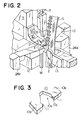
- FIG. 2 is a perspective view of the main structure of the slide fastener coupling element forming apparatus.
- a first ram 1 is horizontally reciprocatingly movably mounted on a frame via a non-illustrated ram guide.
- a cutting die 2 is mounted on the forward end of the first ram 1, having a wire insertion hole for the passage of a blank wire W having a Y-shape cross section.
- a blank wire feed roller 3 and a guide roller 4 supply the blank wire W upwards intermittently at a predetermined pitch corresponding to the thickness of a coupling element E.
- a ram guide 5 Upwardly of the front part of the first ram 1, in which a head portion of the coupling element is to be formed, a ram guide 5 is attached to a non-illustrated set plate supported by the frame.
- the ram guide 5 has a guide groove in which a second ram 6 is vertically movably received in timed relation with the horizontal reciprocating movement of the first ram 1.
- Attached to the front surface of the second ram 6 via a punch holder 7 are a forming punch 8 for forming a bulge on the head portion of the coupling element E and a pressure pad 9 for pressing the opposite leg portions L, L of the coupling element E while the bulge is being formed.
- a cutting punch 10 which is a feature of this invention, is fixed to the lower end of the ram guide 5 so as to frictionally contact the upper surface of the first ram 1.
- the cutting punch 10 has a generally L shape as shown in FIG. 2 and has at its end a bifurcated blade 10a.
- FIG. 3 is a more enlarged perspective view of the blade 10a.
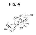
- the bifurcated blade 10a has a pair of confronting arms 10b, 10b with a pair of right and left open ends for holding the blank wire W from opposite side surfaces.
- Each projection 11 defines on its lower side a hollow 10c contiguous to the inside surface of the blade 10a and having a thickness equal to the thickness of a coupling element.
- Each projection 11 may have a suitable length; but assuming that the thickness of the individual coupling element to be cut off the blank wire W is 0.75 mm, the length of the projection 11 should be preferably 0.15 mm in order not to interfere with peripheral parts. These values are only an illustrative example and may be changed, depending on the shape and size of the coupling element.
- the preventing means may be in the form of a bridge member 11a connecting the opposite projections 11, 11 with each other as shown In FIG. 4.
- a pair of side punches 12, 12 are situated at opposite sides of the forming punch 8 for clenching the opposite leg portions L, L of the coupling element E, on the head portion of which a bulge is formed, to attach the coupling element E to a fastener tape T.
- the coupling elements E are successively attached to the fastener tape T.
- the resulting slide fastener stringer S is then intermittently pulled upwardly by a stringer feed roller 14 and a pressure roller 15.
- the foregoing moving parts are actuated by various cams, such as a first-ram drive cam 17, a forming-punch actuation cam 18, a side-punch actuation cam 19, a stringer feed cam 20 and a blank wire feed cam 21, and by various cam follower mechanisms 22 - 26 connected to the respective cams. All of the cams are mounted on a drive output shaft 16 situated on the back side of the first ram 1.
- a roller 22a resting on the first-ram drive cam 17 pivotally mounted on the back part of the first ram 1 is urged forwardly by a compression spring 22b.
- the first ram 1 stops for a predetermined time at each of predetermined forward and backward ends of the stroke.
- the cam follower mechanism 23 for the forming punch 8 includes a roller 23a resting on the forming-punch actuation cam 18, a lever 23b pivotally connected at one end to the roller 23a and at its central portion to the frame body, a pin 23c attached to the other end of the lever 23b and contacting the head of the second ram 6, a non-illustrated compression spring for returning the lever 23b to its original position.
- a non-illustrated compression spring urging the second ram 6 upwardly; as the lever 23b is pivotally moved by the cam 18, the second ram 6 is lowered to return to its original position under the resilience of the non-illustrated compression spring.
- the cam follower mechanism 24 for the side punches 12, 12 includes a roller 24a resting on the side-punch actuation cam 19, a downwardly extending lever 24b pivotally connected at one end to the roller 24a and at its central portion to the frame, a link 24c pivotally connected at its central portion to the other end of the lever 24b, a third ram 24d pivotally connected at its back portion to the front end portion of the link 24c, a pair of actuator levers 24e supporting on their upper portions the side punches 12, 12 and pivotally connected at their central portions to the frame, and a compression spring 24h mounted on the back end of the link 24c. As shown in FIG.
- both sides of the front end portion of the third ram 24d have a pair of outwardly divergent cam surfaces 24f, whom a pair of cam receivers 24g formed on the lower ends of the actuator levers 24e are in contact with.
- the cam receivers 24g cause the actuator levers 24e to pivotally move to actuate the side punches 12, 12.
- the returning of the third ram 24d to its original position takes place by the compression spring 24h.
- the cam follower mechanism 25 for the stringer feed includes, a roller 25a resting on the stringer feed cam 20 as shown in FIG. 1, a first lever 25b pivotally connected at one end to the roller 25a and at the other end to the roller 25c and at its central portion to the frame, and a second lever 25d angularly movable downwardly by the action of the roller 25c and urged upwardly by a compression spring 25f.
- the stringer feed roller 14, in which a one-way clutch (not shown) is mounted, is supported on the base end of the second lever 25d for intermittently feeding the stringer S by its rotation in only one direction.
- the cam follower mechanism 26 for the blank wire feed includes a roller 26a resting on the blank wire feed cam 21, a slider 26b pivotally connected at one end to the roller 26a, a ratchet 26c attached to the other end of the slider 26b, and a ratchet wheel 26d to be turned intermittently at a predetermined angular pitch in only one direction by the ratchet 26c.
- the ratchet wheel 26d and the blank wire feed roller 3 are connected to each other by a transmission shaft 27 so that the blank wire feed roller 3 supplies the blank wire W intermittently.
- the returning of the slider 26b to its original position takes place by a compression spring 26e.
- the coupling element E is formed and attached to the fastener tape in the following manner.
- the supplying of the blank wire W is terminated and a predetermined length of the blank wire W is projected from the cutting die 2.
- the preceding coupling element E has already been attached to the fastener tape T.
- the pulling up of the slide fastener stringer S will be started soon and, at the same time, the first ram 1 will start moving backwardly at the time when the head portion of the coupling element E is released from the non-illustrated forming die connected with the forward end of the cutting die 2. Therefore the attached coupling element E would be free from being caught by the forming die being moved backwardly by the first ram 1.
- the blank wire W is cut by the cutting punch 10.
- the pulling up of the slide fastener stringer S is completed when the first ram 1 is moved backwardly.
- the blank wire W is held by the inside surfaces of the confronting arms 10b, 10b of the blade 10a, and the projections 11, 11 extending from the upper surface of the blade 10a prevents the coupling element E from jumping up obliquely from the blade 10a at the end of cutting.
- the coupling element E is kept reliably inside the confronting arms 10b, 10b until it is moved to the non-illustrated bulge forming die.
- the forming punch 8 with the pressure pad 9 is lowered to form a bulge on the head portion of the coupling element.
- the side punches 12, 12 also are kept stopped and supporting the leg portions L, L of the coupling element E from opposite sides.
- the side punches 12, 12 starts mounting the coupling element E on the fastener tape T, whereupon at the end of the forward stroke of the first ram 1, the first step will start for the next cycle.
- this invention is applied to a coupling element forming and mounting apparatus in which coupling elements are formed and then attached successively to a fastener tape.
- this invention may be applied to a dedicated forming apparatus for forming coupling elements which are to be individually collected outside the apparatus. Also various modifications may be suggested to the foregoing moving parts.
- the preventing means because of the preventing means, it is unnecessary to receive the cut coupling element in intimate contact with the bifurcated blade of the cutting punch like the conventional art, so that a clearance can be created between the coupling element and the inside surface of the bifurcated blade, thus assisting in setting the coupling element exactly in a predetermined posture on the forming die where a bulge is formed on the head portion of the coupling element.
Landscapes
- Engineering & Computer Science (AREA)
- Mechanical Engineering (AREA)
- Slide Fasteners (AREA)
- Forging (AREA)
Description
Claims (5)
- A cutting punch device (10) to be applied to a slide fastener coupling element forming apparatus for successively cutting a blank wire (W) of a generally Y-shape cross section transversely into slices of a predetermined thickness, comprising a blade (10a) having a bifurcate shape such as to hold the blank wire (W) on its side surface, characterized in that said cutting punch (10) is equipped with preventing means (11) on the upper end portion of said blade (10a) for preventing the freshly formed coupling element (E) from jumping up obliquely from said blade (10a) during the cutting.
- A device according to claim 1, wherein a lower surface of said preventing means (11) is spaced from a lower surface of said blade (10a) by a distance corresponding to the thickness of at least one coupling element (E).
- A device according to claim 1 or 2, wherein said preventing means (11) is a pair of confronting projections (11, 11) slightly extending inwardly from the upper end portion of said bifurcated blade (10a).
- A device according to claim 1 or 2, wherein said preventing means (11) is a bridge member (11a) spanning between the end portions of said bifurcated blade (10a).
- An apparatus for successively forming slide fastener coupling elements (E), comprising supplying means (3, 4) for supplying a blank wire (W) of a generally Y-shape cross section intermittently at a predetermined pitch, a cutting die (2) having an insertion hole for the passage of the blank wire W and movable back and forth in a direction of cutting the blank wire (W), a bulge forming die connected with a forward end in the stroke direction of said cutting die (2) for forming a bulge for a coupling head portion of the coupling element (E), a cutting punch (10) fixedly mounted on a frame and slidable on an upper surface of said cutting die (2), and a bulge forming punch (8) situated upwardly of said bulge forming die and vertically movable toward and away from said bulge forming die characterised in that the cutting punch is a device according to one of the preceding claims.
Applications Claiming Priority (2)
| Application Number | Priority Date | Filing Date | Title |
|---|---|---|---|
| JP4195432A JP2744383B2 (en) | 1992-07-22 | 1992-07-22 | Tooth forming apparatus and cutting punch for slide fastener |
| JP195432/92 | 1992-07-22 |
Publications (3)
| Publication Number | Publication Date |
|---|---|
| EP0580064A2 EP0580064A2 (en) | 1994-01-26 |
| EP0580064A3 EP0580064A3 (en) | 1994-08-03 |
| EP0580064B1 true EP0580064B1 (en) | 1998-04-15 |
Family
ID=16340968
Family Applications (1)
| Application Number | Title | Priority Date | Filing Date |
|---|---|---|---|
| EP93111196A Expired - Lifetime EP0580064B1 (en) | 1992-07-22 | 1993-07-13 | Slide fastener coupling element forming apparatus and cutting punch |
Country Status (8)
| Country | Link |
|---|---|
| US (1) | US5361471A (en) |
| EP (1) | EP0580064B1 (en) |
| JP (1) | JP2744383B2 (en) |
| KR (1) | KR970006483B1 (en) |
| CN (1) | CN1084608C (en) |
| BR (1) | BR9302525A (en) |
| CA (1) | CA2100024A1 (en) |
| DE (1) | DE69317948T2 (en) |
Families Citing this family (18)
| Publication number | Priority date | Publication date | Assignee | Title |
|---|---|---|---|---|
| JP3355041B2 (en) * | 1994-08-24 | 2002-12-09 | ワイケイケイ株式会社 | Service teeth for slide fasteners and method and apparatus for forming the same |
| KR100441772B1 (en) * | 1999-01-12 | 2004-07-27 | 주식회사 유니지퍼 | Structure for united cam of apparatus for manufacturing zipper |
| JP4587840B2 (en) * | 2005-02-25 | 2010-11-24 | Ykk株式会社 | Fastener stringer continuous manufacturing equipment |
| JP4641828B2 (en) * | 2005-03-02 | 2011-03-02 | Ykk株式会社 | Feeder for dental metal wire in continuous fastener stringer manufacturing machine |
| JP4602120B2 (en) * | 2005-03-02 | 2010-12-22 | Ykk株式会社 | Fastener tape feeder for continuous fastener stringer |
| KR100666750B1 (en) * | 2005-11-21 | 2007-01-09 | 이방교 | Structured apparatus of united cam for manufacturing zipper |
| CN100488657C (en) * | 2007-07-30 | 2009-05-20 | 王富石 | Water-sealed zip fastener external chain tooth composite punching die |
| CN101497141B (en) * | 2008-01-28 | 2011-06-15 | 福建浔兴拉链科技股份有限公司 | Zipper chamfering mechanism and slide fastener tooth planting machine using the chamfering mechanism |
| CN101731800B (en) * | 2008-11-27 | 2011-12-21 | Ykk株式会社 | Engaged element forming device in zipper teeth chain continuous making machine |
| CN101731797B (en) * | 2008-11-27 | 2012-05-23 | Ykk株式会社 | Zipper teeth chain continuous making machine |
| CN102672465B (en) * | 2011-03-17 | 2016-01-20 | 福建浔兴拉链科技股份有限公司 | The pulling-on piece kludge of slider of zipper fastener |
| CN103386448B (en) * | 2012-05-10 | 2016-01-06 | Ykk株式会社 | The engaged element forming device of slide fastener and the engaged element of slide fastener |
| CN105188458B (en) * | 2013-10-08 | 2018-05-01 | Ykk株式会社 | The transmission device of the sprocket metal wire rod of fastener stringer continuous making machine |
| CN104594009A (en) * | 2015-01-09 | 2015-05-06 | 安徽凯恩特科技有限公司 | Zipper production equipment with material guide function |
| CN106560259B (en) * | 2015-12-01 | 2018-12-14 | 福建晋江浔兴拉链科技有限公司 | Metal tooth, chain tooth molding die and chain tooth processing method |
| WO2017191688A1 (en) * | 2016-05-06 | 2017-11-09 | Ykk株式会社 | Fastener element, manufacturing device for fastener element, and manufacturing method for fastener element |
| WO2019021413A1 (en) * | 2017-07-27 | 2019-01-31 | Ykk株式会社 | Fastener stringer production device |
| CN113399571B (en) * | 2021-06-21 | 2023-04-18 | 东莞大威机械有限公司 | Semi-automatic zipper head dotting device |
Family Cites Families (8)
| Publication number | Priority date | Publication date | Assignee | Title |
|---|---|---|---|---|
| US1947956A (en) * | 1928-12-19 | 1934-02-20 | Hookless Fastener Co | Fastener forming and assembling machine and method of securing fastener elements to tape |
| US2141200A (en) * | 1935-09-03 | 1938-12-27 | Talon Inc | Machine for making fastener stringers |
| US2763051A (en) * | 1949-05-11 | 1956-09-18 | Scovill Manufacturing Co | Machine for making fastener stringers |
| US2804677A (en) * | 1950-11-17 | 1957-09-03 | Talon Inc | Machine for making slide fastener stringers |
| JPS5927667B2 (en) * | 1979-10-29 | 1984-07-07 | ワイケイケイ株式会社 | Method and device for forming elements for slide fasteners |
| JPS5951813B2 (en) * | 1980-09-25 | 1984-12-15 | ワイケイケイ株式会社 | Slide fastener - molding and planting device for janitorial teeth |
| JPS5951812B2 (en) * | 1980-09-25 | 1984-12-15 | ワイケイケイ株式会社 | Method and device for introducing conductor wire for anodizing processing of slide fastener chain |
| JPH0753124B2 (en) * | 1988-12-27 | 1995-06-07 | ワイケイケイ株式会社 | Mounting device for metal working teeth for slide fasteners |
-
1992
- 1992-07-22 JP JP4195432A patent/JP2744383B2/en not_active Expired - Lifetime
-
1993
- 1993-07-07 CA CA002100024A patent/CA2100024A1/en not_active Abandoned
- 1993-07-13 EP EP93111196A patent/EP0580064B1/en not_active Expired - Lifetime
- 1993-07-13 DE DE69317948T patent/DE69317948T2/en not_active Expired - Lifetime
- 1993-07-17 CN CN93108778A patent/CN1084608C/en not_active Expired - Lifetime
- 1993-07-20 US US08/094,341 patent/US5361471A/en not_active Expired - Lifetime
- 1993-07-21 KR KR1019930013802A patent/KR970006483B1/en not_active IP Right Cessation
- 1993-07-22 BR BR9302525A patent/BR9302525A/en not_active IP Right Cessation
Also Published As
| Publication number | Publication date |
|---|---|
| DE69317948T2 (en) | 1998-10-22 |
| US5361471A (en) | 1994-11-08 |
| EP0580064A2 (en) | 1994-01-26 |
| CA2100024A1 (en) | 1994-01-23 |
| EP0580064A3 (en) | 1994-08-03 |
| JP2744383B2 (en) | 1998-04-28 |
| DE69317948D1 (en) | 1998-05-20 |
| CN1084608C (en) | 2002-05-15 |
| CN1081599A (en) | 1994-02-09 |
| BR9302525A (en) | 1994-02-01 |
| JPH0638812A (en) | 1994-02-15 |
| KR940005250A (en) | 1994-03-21 |
| KR970006483B1 (en) | 1997-04-28 |
Similar Documents
| Publication | Publication Date | Title |
|---|---|---|
| EP0580064B1 (en) | Slide fastener coupling element forming apparatus and cutting punch | |
| EP0578178B1 (en) | Method and apparatus for manufacturing slide fastener coupling elements | |
| EP0578171B1 (en) | Slide fastener coupling element forming apparatus | |
| EP0698354B1 (en) | Slide fastener elements and method and apparatus for forming the same | |
| US7757387B2 (en) | Apparatus for continuously manufacturing fastener stringer | |
| TWI511811B (en) | A manufacturing apparatus and a manufacturing method of a zipper chain belt, and a zipper belt | |
| EP0630706B1 (en) | A method and apparatus for forming slide-fastener coupling element | |
| JPS5951813B2 (en) | Slide fastener - molding and planting device for janitorial teeth | |
| KR100668566B1 (en) | Continuous manufacturing apparatus for fastener stringer | |
| JPWO2017191688A1 (en) | Fastener element, fastener element manufacturing apparatus, and fastener element manufacturing method | |
| JP3423479B2 (en) | Method and apparatus for removing fastener element in space of slide fastener chain | |
| EP0030706B1 (en) | Method of and apparatus for interengaging a pair of slide fastener stringers | |
| US4236293A (en) | Method and apparatus for forming space sections in a slide fastener | |
| EP0292110B1 (en) | Method of and apparatus for feeding slide fastener chain with fly strips |
Legal Events
| Date | Code | Title | Description |
|---|---|---|---|
| PUAI | Public reference made under article 153(3) epc to a published international application that has entered the european phase |
Free format text: ORIGINAL CODE: 0009012 |
|
| AK | Designated contracting states |
Kind code of ref document: A2 Designated state(s): CH DE ES FR GB IT LI NL |
|
| PUAL | Search report despatched |
Free format text: ORIGINAL CODE: 0009013 |
|
| AK | Designated contracting states |
Kind code of ref document: A3 Designated state(s): CH DE ES FR GB IT LI NL |
|
| RAP1 | Party data changed (applicant data changed or rights of an application transferred) |
Owner name: YKK CORPORATION |
|
| 17P | Request for examination filed |
Effective date: 19941103 |
|
| 17Q | First examination report despatched |
Effective date: 19960719 |
|
| GRAG | Despatch of communication of intention to grant |
Free format text: ORIGINAL CODE: EPIDOS AGRA |
|
| GRAG | Despatch of communication of intention to grant |
Free format text: ORIGINAL CODE: EPIDOS AGRA |
|
| GRAG | Despatch of communication of intention to grant |
Free format text: ORIGINAL CODE: EPIDOS AGRA |
|
| GRAH | Despatch of communication of intention to grant a patent |
Free format text: ORIGINAL CODE: EPIDOS IGRA |
|
| GRAH | Despatch of communication of intention to grant a patent |
Free format text: ORIGINAL CODE: EPIDOS IGRA |
|
| GRAA | (expected) grant |
Free format text: ORIGINAL CODE: 0009210 |
|
| AK | Designated contracting states |
Kind code of ref document: B1 Designated state(s): CH DE ES FR GB IT LI NL |
|
| PG25 | Lapsed in a contracting state [announced via postgrant information from national office to epo] |
Ref country code: NL Free format text: LAPSE BECAUSE OF FAILURE TO SUBMIT A TRANSLATION OF THE DESCRIPTION OR TO PAY THE FEE WITHIN THE PRESCRIBED TIME-LIMIT Effective date: 19980415 Ref country code: LI Free format text: LAPSE BECAUSE OF FAILURE TO SUBMIT A TRANSLATION OF THE DESCRIPTION OR TO PAY THE FEE WITHIN THE PRESCRIBED TIME-LIMIT Effective date: 19980415 Ref country code: ES Free format text: THE PATENT HAS BEEN ANNULLED BY A DECISION OF A NATIONAL AUTHORITY Effective date: 19980415 Ref country code: CH Free format text: LAPSE BECAUSE OF FAILURE TO SUBMIT A TRANSLATION OF THE DESCRIPTION OR TO PAY THE FEE WITHIN THE PRESCRIBED TIME-LIMIT Effective date: 19980415 |
|
| REG | Reference to a national code |
Ref country code: CH Ref legal event code: EP |
|
| ITF | It: translation for a ep patent filed |
Owner name: JACOBACCI & PERANI S.P.A. |
|
| ET | Fr: translation filed | ||
| REF | Corresponds to: |
Ref document number: 69317948 Country of ref document: DE Date of ref document: 19980520 |
|
| PG25 | Lapsed in a contracting state [announced via postgrant information from national office to epo] |
Ref country code: GB Free format text: LAPSE BECAUSE OF NON-PAYMENT OF DUE FEES Effective date: 19980715 |
|
| NLV1 | Nl: lapsed or annulled due to failure to fulfill the requirements of art. 29p and 29m of the patents act | ||
| REG | Reference to a national code |
Ref country code: CH Ref legal event code: PL |
|
| PLBE | No opposition filed within time limit |
Free format text: ORIGINAL CODE: 0009261 |
|
| STAA | Information on the status of an ep patent application or granted ep patent |
Free format text: STATUS: NO OPPOSITION FILED WITHIN TIME LIMIT |
|
| GBPC | Gb: european patent ceased through non-payment of renewal fee |
Effective date: 19980715 |
|
| 26N | No opposition filed | ||
| PGFP | Annual fee paid to national office [announced via postgrant information from national office to epo] |
Ref country code: FR Payment date: 20100805 Year of fee payment: 18 |
|
| REG | Reference to a national code |
Ref country code: FR Ref legal event code: ST Effective date: 20120330 |
|
| PG25 | Lapsed in a contracting state [announced via postgrant information from national office to epo] |
Ref country code: FR Free format text: LAPSE BECAUSE OF NON-PAYMENT OF DUE FEES Effective date: 20110801 |
|
| PGFP | Annual fee paid to national office [announced via postgrant information from national office to epo] |
Ref country code: IT Payment date: 20120714 Year of fee payment: 20 Ref country code: DE Payment date: 20120711 Year of fee payment: 20 |
|
| REG | Reference to a national code |
Ref country code: DE Ref legal event code: R071 Ref document number: 69317948 Country of ref document: DE |
|
| PG25 | Lapsed in a contracting state [announced via postgrant information from national office to epo] |
Ref country code: DE Free format text: LAPSE BECAUSE OF EXPIRATION OF PROTECTION Effective date: 20130716 |