EP0579948A1 - Control system for an asynchronous motor - Google Patents
Control system for an asynchronous motor Download PDFInfo
- Publication number
- EP0579948A1 EP0579948A1 EP93109442A EP93109442A EP0579948A1 EP 0579948 A1 EP0579948 A1 EP 0579948A1 EP 93109442 A EP93109442 A EP 93109442A EP 93109442 A EP93109442 A EP 93109442A EP 0579948 A1 EP0579948 A1 EP 0579948A1
- Authority
- EP
- European Patent Office
- Prior art keywords
- frequency
- signal
- value
- unit
- amplitude
- Prior art date
- Legal status (The legal status is an assumption and is not a legal conclusion. Google has not performed a legal analysis and makes no representation as to the accuracy of the status listed.)
- Granted
Links
Images

Classifications
-
- B—PERFORMING OPERATIONS; TRANSPORTING
- B60—VEHICLES IN GENERAL
- B60L—PROPULSION OF ELECTRICALLY-PROPELLED VEHICLES; SUPPLYING ELECTRIC POWER FOR AUXILIARY EQUIPMENT OF ELECTRICALLY-PROPELLED VEHICLES; ELECTRODYNAMIC BRAKE SYSTEMS FOR VEHICLES IN GENERAL; MAGNETIC SUSPENSION OR LEVITATION FOR VEHICLES; MONITORING OPERATING VARIABLES OF ELECTRICALLY-PROPELLED VEHICLES; ELECTRIC SAFETY DEVICES FOR ELECTRICALLY-PROPELLED VEHICLES
- B60L50/00—Electric propulsion with power supplied within the vehicle
- B60L50/50—Electric propulsion with power supplied within the vehicle using propulsion power supplied by batteries or fuel cells
- B60L50/51—Electric propulsion with power supplied within the vehicle using propulsion power supplied by batteries or fuel cells characterised by AC-motors
-
- Y—GENERAL TAGGING OF NEW TECHNOLOGICAL DEVELOPMENTS; GENERAL TAGGING OF CROSS-SECTIONAL TECHNOLOGIES SPANNING OVER SEVERAL SECTIONS OF THE IPC; TECHNICAL SUBJECTS COVERED BY FORMER USPC CROSS-REFERENCE ART COLLECTIONS [XRACs] AND DIGESTS
- Y02—TECHNOLOGIES OR APPLICATIONS FOR MITIGATION OR ADAPTATION AGAINST CLIMATE CHANGE
- Y02T—CLIMATE CHANGE MITIGATION TECHNOLOGIES RELATED TO TRANSPORTATION
- Y02T10/00—Road transport of goods or passengers
- Y02T10/60—Other road transportation technologies with climate change mitigation effect
- Y02T10/70—Energy storage systems for electromobility, e.g. batteries
-
- Y—GENERAL TAGGING OF NEW TECHNOLOGICAL DEVELOPMENTS; GENERAL TAGGING OF CROSS-SECTIONAL TECHNOLOGIES SPANNING OVER SEVERAL SECTIONS OF THE IPC; TECHNICAL SUBJECTS COVERED BY FORMER USPC CROSS-REFERENCE ART COLLECTIONS [XRACs] AND DIGESTS
- Y02—TECHNOLOGIES OR APPLICATIONS FOR MITIGATION OR ADAPTATION AGAINST CLIMATE CHANGE
- Y02T—CLIMATE CHANGE MITIGATION TECHNOLOGIES RELATED TO TRANSPORTATION
- Y02T10/00—Road transport of goods or passengers
- Y02T10/60—Other road transportation technologies with climate change mitigation effect
- Y02T10/72—Electric energy management in electromobility
Definitions
- the present invention relates to a device for controlling an asynchronous motor, in particular intended for the traction system of a vehicle of the electric type.
- a type of asynchronous motor known to those skilled in the art comprises a stator comprising a first winding and a rotor comprising a second winding electrically closed on itself.
- the first coil When connected to a polyphase electrical power source producing an alternating supply current, the first coil generates a rotating magnetic field in the region of the rotor.
- the flow of the rotating magnetic field which crosses the second winding of the rotor induces in this second winding an induced voltage generating an electric current induced in the latter.
- the rotor is subjected to an electromagnetic force, resulting from the coupling between the rotating magnetic field and the electric current induced in the second winding, which generates a moment of force on the motor output shaft.
- the saturation value of the magnetic flux passing through the winding of said rotor defines, for a value of the stator frequency FST, a saturation value for the amplitude of the supply voltage, this saturation value being determined by the nature and the dimensions of the engine.
- the nominal operating curve of such an asynchronous motor is generally characterized, on a graph giving the amplitude of the supply voltage as a function of the frequency of this supply voltage, by a substantially affine curve, corresponding to a substantially constant force moment for constant sliding, on a first frequency range, the maximum value of which corresponds to the maximum nominal amplitude of the supply voltage, this substantially refined curve being extended over a second frequency range succeeding said first frequency range by a substantially constant curve located at the level of the maximum nominal amplitude of the supply voltage.
- the nominal supply curve fixes for each frequency of the supply voltage, respectively stator frequency FST a fixed and predetermined amplitude for the supply voltage.
- stator frequency FST a fixed and predetermined amplitude for the supply voltage.
- the control of an asynchronous motor by means of an electronic device is arranged so that the operating point remains on the predetermined nominal supply curve.
- Such control of an asynchronous motor has several drawbacks. Firstly, given that for a given supply frequency one always works with a nominal amplitude of the voltage, the losses generated are relatively large whatever the moment of force requested, in particular as regards the iron losses. Secondly, varying the slip S to vary the force moment leads to non-optimal use of the motor. Indeed, the efficiency of an asynchronous motor depends on the slip value and therefore on the frequency difference between the stator frequency FST and the rotor frequency FRT.
- the nominal amplitude of the voltage is too high for the moment of force requested and the resulting slip is relatively low, which leads to a non-optimal engine speed.
- the nominal amplitude of the supply voltage relatively far from the amplitude of saturation, leads to a relatively large increase in slip, which again places the engine in a non-optimal speed, the losses this time being relatively large because of the high supply current required.
- the object of the present invention is to overcome the drawbacks of the control device described above.
- the first and second means for adjusting the supply voltage are arranged so that said frequency difference is capable of being increased as a function of a second adjustment signal when, for a given value of the stator frequency, the amplitude of the supply voltage has a value equal to said maximum value defined for this value of the stator frequency.
- the electronic control described above therefore has great flexibility in using the possibilities of the motor.
- it makes it possible to limit losses since it allows operation below the nominal amplitude of the supply voltage when the requested force moment can be provided with an optimal fixed frequency difference for an amplitude of the supply voltage lower than this nominal amplitude.
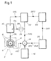
- the asynchronous motor 2 comprises a stator 4 and a rotor 6, the stator 4 comprising a coil 8 connected to electrical supply means 10.
- the electrical supply means 10 are arranged so as to provide an alternating supply voltage, independently variable in amplitude and in frequency, capable of generating a supply current IAL in the winding 8 of the stator 4.
- the supply current IAL supplied by the electric supply 10 is also alternating and for example three-phase.
- Power supplies for producing an alternating voltage whose frequency and amplitude can be varied independently of one another at the terminals of a coil are known to those skilled in the art.
- power supplies include a pulse width modulator ("PWM: Pulse-Width-Modulator” in English) actuating a power switch, the latter being connected to a source of electrical energy whose value of voltage it provides is substantially constant.
- PWM Pulse-Width-Modulator
- Such a source of electrical energy is for example formed by a battery which can be installed in an electric vehicle.
- the stator winding 8 is arranged in such a way that said alternating supply current flowing in this stator winding generates a magnetic field rotating at a stator frequency FST in the region of the rotor 6, the latter having a rotor frequency FRT of rotation in response to the rotating magnetic flux.
- the frequency of rotation FRT of the rotor is measured using a detector 12 which produces a signal representative of this rotor frequency FRT and transmits it to an adder 14 to which the detector 12 is connected.
- the adder 14 is also connected to a unit 16 arranged so that it provides a signal representative of a fixed frequency difference DFI, as well as to a unit 20 for adjusting the difference in frequency of rotation between said frequency stator frequency FST and said rotor frequency FRT.
- This unit 20 is arranged so as to produce a signal representative of a variable frequency difference DVA as a function of an adjustment signal SR1 coming from a reference unit 30, this signal being supplied to said adder 14.
- the adder 14 is finally connected to the electrical supply 10 and to a unit 22 for adjusting the amplitude UAL of the supply voltage to which it supplies a signal representative of a resulting frequency FRS.
- This last signal transmitted to an input 10b of the electrical supply 10 defines for this electrical supply a signal for controlling the frequency FAL of the supply voltage under which it must supply the alternating supply current IAL to the motor 2.
- an amplifier 26 is provided on the electrical path 28 connecting the adder 14 to the electrical supply 10. This amplifier 26 generates a signal which defines in this case the control signal of the frequency FAL of the supply voltage under which the supply electric must supply the alternating supply current IAL to the motor 2.
- the unit 22 determines a value for the amplitude UAL of the supply voltage and transmits this value in the form of d 'A signal at an input 10a of the power supply 10, this signal defining a signal for controlling the amplitude UAL of the supply voltage.
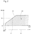
- FIG. 2 defines a supply domain 38 on a graph giving the amplitude UAL of the supply voltage as a function of the stator frequency FST, the value of the latter being an integer multiple of the value of the frequency FAL of the supply voltage.
- the set of values that the stator frequency FST is capable of taking defines a range 40 of frequency values accessible at this stator frequency FST.
- the amplitude UAL of the supply voltage is liable to vary between a minimum value U1 and a maximum value U2, these values being defined specifically for each frequency value 41 of said range 40.
- the set of maximum values U2 defines a voltage limit curve 42.
- the control device is arranged so that firstly, the stator frequency FST, the value of which is defined by the resulting frequency FRS, is equal to the sum of the rotor frequency FRT and the fixed frequency difference DFI both that the amplitude UAL of the supply voltage, defined by the unit 22, has a value less than the maximum value U2 for this stator frequency FST, which corresponds to a zero value for the variable frequency difference DVA, and that secondly, the variable frequency difference DVA is likely to have a non-zero value when the amplitude UAL of the supply voltage is equal to a maximum value U2 belonging to the voltage limit curve 42.
- the unit 22 is firstly arranged so that, for any value of the resulting frequency FRS, the signal of the amplitude UAL of the supply voltage which it supplies to the power supply 10, response to the signal setting SR2, takes a value lower than the maximum value U2 corresponding to this value of the resulting frequency FRS for a non-empty set E1 of values accessible to the setting signal SR2.
- the units 20 and 30 are arranged so that the adjustment signal SR1 takes a value in a non-empty set E2 of values accessible to this adjustment signal SR1 when the value of the adjustment signal SR2 belongs to the set E1, and that in this case the unit 20 produces at its output a signal representative of a variable frequency difference DVA whose value is zero.
- the unit 22 is arranged so that, for any value of the resulting frequency FRS, said signal of the amplitude UAL has a value equal to the maximum value U2 corresponding to this value of the resulting frequency FRS for a set E3 non-empty values accessible to the adjustment signal SR2.
- the units 20 and 30 are arranged so that the adjustment signal SR1 takes a value in a non-empty set E4 of values accessible to this adjustment signal SR1 when the value of the adjustment signal SR2 belongs to the set E3 , and that in this case the unit 20 produces at its output, for at least one setting value SR1 belonging to the set E4, a signal representative of a variable frequency difference DVA whose value is non-zero .
- the control device of an asynchronous motor according to the invention thus makes it possible to operate the motor at an optimal speed over substantially the entire power range 38 and also to make maximum use of the possibilities of the asynchronous motor used when requested .
- FIGS. 3 to 7 Using FIGS. 3 to 7, a first embodiment of a device for controlling an asynchronous motor according to the invention will be described below.
- the asynchronous motor 2 comprises a stator 4 and a rotor 6, the stator 4 comprising a winding 8 connected to an electrical supply 10.
- a detector 12 of the frequency of rotation FRT of the rotor is connected to the input 50c of an adder 50, as well as to a setpoint unit 52.
- the setpoint unit 52 is also connected to the input 54a of a unit 54 for determining an amplification coefficient and at the input 56a for a unit 56 for adjusting the difference in rotation frequency between the stator frequency and the rotor frequency.
- the output 56b of the unit 56 is connected to the input 50a of the adder 50.
- a unit 58 producing a signal representative of a fixed and predetermined frequency difference DFI is also connected to an input 50b of the adder 50
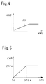
- the output 50d of the latter is connected to the input 10b of the power supply 10, as well as to the input 60a of a unit 60 in which is stored a normalized voltage-frequency curve 55 shown diagrammatically in the figure. 4.
- the output 60b of the unit 60 is connected to the input 62b of a multiplier 62 which still has an input 62a connected to an output 54b of the unit 54 used to determine the amplification coefficient CAP. Finally, the output 62c of the multiplier 62 is connected to the input 10a of the power supply 10.
- the setpoint unit 52 is arranged so as to produce an adjustment signal SRG, the values capable of being taken by this adjustment signal depending on the rotation frequency FRT of the rotor whose value is communicated to the setpoint unit 52 by means of the detector 12.
- SRG an adjustment signal
- FIG. 7 is shown diagrammatically the domain 65 of the values that the adjustment signal is capable of taking as a function of the frequency of rotation FRT of the rotor and in particular the maximum adjustment value SR1 for each FR1 value of this rotor rotation frequency, the limit curve 66 of this domain 65 being defined by the characteristics of the motor 2 used.
- the SRG adjustment signal produced by the setpoint unit 52 is transmitted to the unit 54 and to the unit 56.
- the unit 54 in response to the SRG adjustment signal produces a signal representative of an amplification coefficient CAP.
- the unit 56 produces, in response to the adjustment signal SRG, a signal representative of a variable frequency difference DVA transmitted to the adder 50.
- the adder 50 adds the DVA signal with the DFI signal and the FRT signal.
- the adder 50 produces a signal resulting from this addition which is representative of a resulting frequency FRS.
- This resulting signal is transmitted to the power supply 10 via an amplifier 70, the latter being necessary only if the number of pairs of poles of the stator winding 8 is different from 1.
- the amplifier 70 multiplies the signal by an integer P corresponding to the number of pairs of poles of the stator winding 8.
- Said resulting signal defines a signal for controlling the frequency FAL of the supply voltage for the power supply 10.
- the signal representative of the resulting frequency FRS is also transmitted to the unit 60 which supplies in response to this signal a signal representative of a normalized amplitude UNO of voltage.
- the curve 55 which determines the normalized amplitude UNO of voltage as a function of the resulting frequency FRS, is proportional to the limit voltage curve 42 shown diagrammatically in FIG. 2.
- the normalized voltage UNO is multiplied in the multiplier 62 by the amplification coefficient CAP supplied by the unit 54.
- the multiplier 62 then supplies the power supply 10 with a signal for controlling the amplitude UAL of the supply voltage , this power supply 10 supplying voltage to the stator winding 8 of the motor 2 with this amplitude UAL in response to this signal supplied.
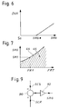
- control device according to the invention described with the aid of FIGS. 1 and 2 is achieved in particular by virtue of the characteristic of the unit 54 represented in FIG. 5, the latter being used to determine the amplification coefficient CAP , and to the characteristic of the unit 56 shown in FIG. 6, the latter being used for adjusting the frequency difference between the stator frequency FST and the rotor frequency FRT.
- the value of the variable frequency difference DVA is fixed at zero as long as the adjustment signal SRG is below a given value SRG *.
- the amplification coefficient CAP increases substantially linearly as a function of the adjustment signal SRG between the initial value S0 and the value SRG *. Note, however, that it is possible to predict that the variable frequency difference DVA will increase slightly and progressively between the value 50 and the value SRG * of the adjustment signal SRG to optimize the efficiency of the asynchronous motor.
- the CAP amplification coefficient reaches its maximum CAP * value.
- the amplification coefficient is maintained at the maximum value CAP *.
- This CAP * coefficient is determined so that the normalized voltage-frequency curve 55 in FIG. 4 multiplied by this CAP * coefficient gives the voltage limit curve 42 shown diagrammatically in FIG. 2, this voltage limit curve 42 being predetermined as a function characteristics and dimensions of the engine.
- the resulting frequency FRS equivalent to the stator frequency FST, corresponds to the rotor frequency to which an optimal fixed frequency difference DFI has been added.
- the signal representative of the amplitude UAL of the supply voltage transmitted by the multiplier 62 to the power supply 10 is likely to vary, for each value of the resulting frequency FRS equivalent to the stator frequency FST represented in FIG. 2, between the minimum value U1 and the maximum value U2 belonging to the limit voltage curve 42, as shown diagrammatically on this figure 2.
- the adjustment signal SRG * therefore corresponds to a transient adjustment between two supply regimes.
- the amplification coefficient CAP keeps a constant value CAP *, which has the effect that the signal controlling the amplitude UAL of the voltage power supply is representative of a value of the limit voltage curve 42, whatever the value of the resulting frequency FRS.
- the adjustment signal SRG is equal to SRG *, the maximum moment of force supplied by the motor 2 has been reached for a given rotor frequency FRT for a fixed frequency difference DFI between the stator frequency and the rotor frequency.
- the force moment supplied by the motor is increased, for a given rotor frequency FRT, by increasing the difference in frequency of rotation between the stator frequency FST and this rotor frequency FRT, as shown in FIG. 6.
- the signal representative of the variable frequency difference DVA produced by the unit 56 and supplied to the adder 50, is greater than zero when the adjustment signal SRG has a value greater than SRG *.
- This increase in the difference in frequency of rotation between the stator frequency and the rotor frequency is increased as a function of the frequency of rotation FRT of the rotor by the limit curve 66 shown in FIG. 7.
- the difference Variable frequency DVA is kept constant when it has reached a predetermined maximum value; that is to say that from a certain value of the adjustment signal, an increase in this adjustment signal no longer generates an increase in the variable frequency difference DVA.
- the amplitude UAL of the supply voltage increases, for a given rotation frequency FRT of the rotor, between the minimum value U1 and the maximum value U2, predetermined for the stator frequency FST equal to this rotor frequency FRT at which an optimal fixed frequency difference DFI has been added, when the adjustment signal increases between the initial value S0 and the value SRG *.
- the difference in frequency between the stator frequency FST and the rotor frequency FRT increases, which corresponds to an increase in slip, and the amplitude of the supply voltage under which the energy source electric supplies the motor 2 takes the maximum possible value for the value of the resulting frequency FRS, respectively the stator frequency FST resulting from the increase in the frequency difference.
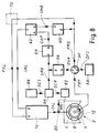
- FIG. 8 shows a second embodiment of a control device according to the invention, this control device according to the invention used to adjust the supply current IAL.
- an instrument 80 for measuring the supply current IAL flowing between the power supply 10 and the stator winding 8 is provided.
- the supply current IAL is three-phase, only the measurement of the current over two phases is necessary, as shown diagrammatically in FIG. 8
- the device 80 for measuring the supply current produces an MRC signal representative of the measurement of the current which is transmitted to a unit 82 for processing this signal.
- This unit 82 produces in response to the signal MCR a processed signal SCR which is transmitted to a unit 84 responsible for producing the adjustment signal SRG.
- the unit 84 is also connected to a unit 86 serving as a set point, for example an accelerator pedal of an electric vehicle.
- This unit 86 produces a reference signal SCS transmitted to the unit 84.
- the unit 84 produces an adjustment signal SRG in response to the two signals SCR and SCS.
- FIG. 9 An embodiment of the electronics of the unit 84 producing the adjustment signal SRG is represented in FIG. 9.
- the reference signal SCS and the processed signal SCR of the measurement of the current of IAL power supply are subtracted from each other using a differentiator 90.
- the result of this differentiation is then transmitted to a regulator 92 proportional to the integral.
- the outgoing signal from regulator 92 (in particular a voltage signal) in this case constitutes the adjustment signal SRG.
- the rest of the command according to the second embodiment shown in FIG. 8 is similar to the first embodiment shown in FIG. 3 except for the limitation of the value of the adjustment signal SRG as a function of the value of the rotor frequency FRT as shown in FIG. 7.
- a maximum value is provided for the setpoint signal which imposes a maximum value on the supply current IAL and ensures for any rotor frequency an operation below the saturation point of the motor.
- the value of the adjustment signal SRG varies as long as the value SCR of the signal processed from the measurement of current MCR is different from the set value SCS.
- the value of the adjustment signal SRG remains constant.
- the maximum value of the setpoint signal SCS that the unit 86 is capable of transmitting to the unit 84 for producing the adjustment signal SRG thus determines the maximum value for the supply current IAL of the asynchronous motor 2, this maximum value being predetermined according to the characteristics of this asynchronous motor 2.
Abstract
Description
La présente invention concerne un dispositif de commande d'un moteur asynchrone, notamment destiné au système de traction d'un véhicule du type électrique.The present invention relates to a device for controlling an asynchronous motor, in particular intended for the traction system of a vehicle of the electric type.
Un type de moteur asynchrone connu de l'homme de métier comporte un stator comprenant un premier bobinage et un rotor comprenant un second bobinage fermé électriquement sur lui-même.A type of asynchronous motor known to those skilled in the art comprises a stator comprising a first winding and a rotor comprising a second winding electrically closed on itself.
Lorsqu'il est relié à une source d'énergie électrique polyphasée produisant un courant d'alimentation alternatif, le premier bobinage engendre un champ magnétique tournant dans la région du rotor. Lorsque le rotor a une fréquence de rotation différente de la fréquence de rotation du champ magnétique tournant, le flux du champ magnétique tournant qui traverse le second bobinage du rotor induit dans ce second bobinage une tension induite engendrant un courant électrique induit dans celui-ci. Dans ce dernier cas, le rotor est soumis à une force électromagnétique, résultante du couplage entre le champ magnétique tournant et le courant électrique induit dans le second bobinage, qui engendre sur l'arbre de sortie du moteur un moment de force.When connected to a polyphase electrical power source producing an alternating supply current, the first coil generates a rotating magnetic field in the region of the rotor. When the rotor has a rotation frequency different from the rotation frequency of the rotating magnetic field, the flow of the rotating magnetic field which crosses the second winding of the rotor induces in this second winding an induced voltage generating an electric current induced in the latter. In the latter case, the rotor is subjected to an electromagnetic force, resulting from the coupling between the rotating magnetic field and the electric current induced in the second winding, which generates a moment of force on the motor output shaft.
Pour un moteur asynchrone, on peut définir un glissement S par la formule suivante :
![]()
ou :
- FST
- = Fréquence de rotation du champ magnétique tournant engendré par le courant d'alimentation,
- FRT
- = Fréquence de rotation du rotor.
or :
- FST
- = Frequency of rotation of the rotating magnetic field generated by the supply current,
- FRT
- = Rotation frequency of the rotor.
Pour une fréquence statorique FST et une amplitude de la tension d'alimentation données, on observe une augmentation du courant d'alimentation lorsque le glissement S augmente, ainsi qu'une augmentation du moment de force lorsque le glissement varie entre une valeur nulle et une valeur de bascule pour laquelle le moment de force maximum est atteint. La plage de valeurs du glissement comprise entre la valeur nulle et la valeur de bascule définit une plage de travail du moteur pour une fréquence statorique FST et une amplitude de la tension d'alimentation données.For a stator frequency FST and an amplitude of the given supply voltage, an increase in the supply current is observed when the slip S increases, as well as an increase in the moment of force when the slip varies between a zero value and a rocker value for which the maximum moment of force is reached. The range of slip values between the zero value and the rocker value defines a working range of the motor for a stator frequency FST and an amplitude of the given supply voltage.
D'un autre côté, pour une fréquence statorique FST et un glissement S donnés, on observe une augmentation du moment de force lorsque l'amplitude de la tension d'alimentation augmente et tant que le moteur n'a pas atteint la saturation magnétique.On the other hand, for a given stator frequency FST and a slip S, there is an increase in the moment of force when the amplitude of the supply voltage increases and as long as the motor has not reached magnetic saturation.
On remarquera que la valeur de saturation du flux magnétique traversant le bobinage dudit rotor définit, pour une valeur de la fréquence statorique FST, une valeur de saturation pour l'amplitude de la tension d'alimentation, cette valeur de saturation étant déterminée par la nature et les dimensions du moteur.It will be noted that the saturation value of the magnetic flux passing through the winding of said rotor defines, for a value of the stator frequency FST, a saturation value for the amplitude of the supply voltage, this saturation value being determined by the nature and the dimensions of the engine.
Comme le flux magnétique est sensiblement proportionnel à l'amplitude de la tension d'alimentation et inversement proportionnel à la fréquence de cette tension d'alimentation (multiple entier de la fréquence statorique), la courbe de fonctionnement nominale d'un tel moteur asynchrone est généralement caractérisée, sur un graphe donnant l'amplitude de la tension d'alimentation en fonction de la fréquence de cette tension d'alimentation, par une courbe sensiblement affine, correspondant à un moment de force sensiblement constant pour un glissement constant, sur une première plage de fréquence dont la valeur maximale correspond à l'amplitude nominale maximale de la tension d'alimentation, cette courbe sensiblement affine étant prolongée sur une deuxième plage de fréquence succédant à ladite première plage de fréquence par une courbe sensiblement constante située au niveau de l'amplitude nominale maximale de la tension d'alimentation.As the magnetic flux is substantially proportional to the amplitude of the supply voltage and inversely proportional to the frequency of this supply voltage (integer multiple of the stator frequency), the nominal operating curve of such an asynchronous motor is generally characterized, on a graph giving the amplitude of the supply voltage as a function of the frequency of this supply voltage, by a substantially affine curve, corresponding to a substantially constant force moment for constant sliding, on a first frequency range, the maximum value of which corresponds to the maximum nominal amplitude of the supply voltage, this substantially refined curve being extended over a second frequency range succeeding said first frequency range by a substantially constant curve located at the level of the maximum nominal amplitude of the supply voltage.
La courbe d'alimentation nominale fixe pour chaque fréquence de la tension d'alimentation, respectivement fréquence statorique FST une amplitude fixe et prédéterminée pour la tension d'alimentation. Ainsi, pour une fréquence statorique donnée, la variation du moment de force sur l'arbre du moteur est obtenue par une variation du glissement S lorsque le point de fonctionnement du moteur est situé sur la courbe d'alimentation nominale.The nominal supply curve fixes for each frequency of the supply voltage, respectively stator frequency FST a fixed and predetermined amplitude for the supply voltage. Thus, for a given stator frequency, the variation of the force moment on the motor shaft is obtained by a variation of the slip S when the motor operating point is located on the nominal supply curve.
Généralement, la commande d'un moteur asynchrone au moyen d'un dispositif électronique est agencée de manière que le point de fonctionnement reste sur la courbe d'alimentation nominale prédéterminée. Une telle commande d'un moteur asynchrone présente plusieurs inconvénients. Premièrement, étant donné que pour une fréquence d'alimentation donnée on travaille toujours avec une amplitude nominale de la tension, les pertes engendrées sont relativement importantes quel que soit le moment de force demandé, en particulier pour ce qui concerne les pertes fer. Deuxièmement, le fait de varier le glissement S pour varier le moment de force conduit à une utilisation non-optimale du moteur. En effet, le rendement d'un moteur asynchrone dépend de la valeur du glissement et donc de la différence de fréquence entre la fréquence statorique FST et la fréquence rotorique FRT.Generally, the control of an asynchronous motor by means of an electronic device is arranged so that the operating point remains on the predetermined nominal supply curve. Such control of an asynchronous motor has several drawbacks. Firstly, given that for a given supply frequency one always works with a nominal amplitude of the voltage, the losses generated are relatively large whatever the moment of force requested, in particular as regards the iron losses. Secondly, varying the slip S to vary the force moment leads to non-optimal use of the motor. Indeed, the efficiency of an asynchronous motor depends on the slip value and therefore on the frequency difference between the stator frequency FST and the rotor frequency FRT.
Ainsi, dans la plupart des cas, l'amplitude nominale de la tension est trop élevée pour le moment de force demandé et le glissement résultant est relativement faible, ce qui conduit à un régime non-optimal du moteur. Dans d'autres cas, lorsque le moment de force demandé est relativement grand, l'amplitude nominale de la tension d'alimentation, relativement éloignée de l'amplitude de saturation, conduit à une augmentation relativement importante du glissement, ce qui place à nouveau le moteur dans un régime non-optimal, les pertes étant cette fois-ci relativement importantes à cause du fort courant d'alimentation nécessaire.Thus, in most cases, the nominal amplitude of the voltage is too high for the moment of force requested and the resulting slip is relatively low, which leads to a non-optimal engine speed. In other cases, when the moment of force requested is relatively large, the nominal amplitude of the supply voltage, relatively far from the amplitude of saturation, leads to a relatively large increase in slip, which again places the engine in a non-optimal speed, the losses this time being relatively large because of the high supply current required.
Le but de la présente invention est de pallier les inconvénients du dispositif de commande décrit ci-dessus.The object of the present invention is to overcome the drawbacks of the control device described above.
L'invention a donc pour objet un dispositif de commande d'un moteur asynchrone, ce dernier comprenant :
- un bobinage statorique agencé de manière à produire un champ magnétique tournant à une fréquence statorique en réponse à une tension d'alimentation alternative appliquée audit bobinage statorique et produisant un courant d'alimentation;
- un rotor comportant un bobinage rotorique couplé magnétiquement audit bobinage statorique, ce rotor ayant une fréquence rotorique de rotation en réponse audit champ magnétique tournant;
- a stator winding arranged to produce a magnetic field rotating at a stator frequency in response to an alternating supply voltage applied to said stator winding and producing a supply current;
- a rotor comprising a rotor winding magnetically coupled to said stator winding, this rotor having a rotor frequency of rotation in response to said rotating magnetic field;
Il résulte de ces caractéristiques une utilisation relativement optimale du moteur sur tout un domaine de fonctionnement. En effet, on observe que le rendement optimal est obtenu pour une différence de fréquence sensiblement constante entre la fréquence statorique et la fréquence rotorique, quelle que soit la fréquence statorique et l'amplitude de la tension d'alimentation et tant que cette dernière engendre un flux magnétique traversant le bobinage du rotor suffisamment éloigné du flux de saturation. La valeur de ladite différence de fréquence conduisant au rendement optimal est déterminée en fonction des caractéristiques du moteur asynchrone utilisé.The result of these characteristics is a relatively optimal use of the engine over an entire operating range. Indeed, it is observed that the optimal efficiency is obtained for a substantially constant frequency difference between the stator frequency and the rotor frequency, whatever the stator frequency and the amplitude of the supply voltage and as long as the latter generates a magnetic flux passing through the rotor winding sufficiently distant from the saturation flux. The value of said frequency difference leading to optimal efficiency is determined according to the characteristics of the asynchronous motor used.
Selon une autre caractéristique du dispositif de commande selon l'invention, les premiers et deuxièmes moyens de réglage de la tension d'alimentation sont agencés de manière que ladite différence de fréquence est susceptible d'être augmentée en fonction d'un deuxième signal de réglage lorsque, pour une valeur donnée de la fréquence statorique, l'amplitude de la tension d'alimentation a une valeur égale à ladite valeur maximale définie pour cette valeur de la fréquence statorique.According to another characteristic of the control device according to the invention, the first and second means for adjusting the supply voltage are arranged so that said frequency difference is capable of being increased as a function of a second adjustment signal when, for a given value of the stator frequency, the amplitude of the supply voltage has a value equal to said maximum value defined for this value of the stator frequency.
Il résulte de cette caractéristique la possibilité d'augmenter la valeur de la puissance fournie par le moteur jusqu'à une valeur limite pour laquelle on exploite au maximum le potentiel du moteur. En effet, la courbe limite de tension peut être située relativement près de la saturation magnétique du moteur et en augmentant le glissement, le moment de force est augmenté tant que la valeur de ce glissement est située dans le domaine de travail.This characteristic results in the possibility of increasing the value of the power supplied by the motor to a limit value for which the potential of the motor is exploited to the maximum. Indeed, the voltage limit curve can be located relatively close to the magnetic saturation of the motor and by increasing the slip, the moment of force is increased as long as the value of this slip is located in the working area.
La commande électronique décrite ci-dessus présente donc une grande souplesse dans l'utilisation des possibilités du moteur. De plus, elle permet de limiter les pertes puisqu'elle permet un fonctionnement en-dessous de l'amplitude nominale de la tension d'alimentation lorsque le moment de force demandé peut être fournit avec une différence de fréquence fixe optimale pour une amplitude de la tension d'alimentation inférieure à cette amplitude nominale.The electronic control described above therefore has great flexibility in using the possibilities of the motor. In addition, it makes it possible to limit losses since it allows operation below the nominal amplitude of the supply voltage when the requested force moment can be provided with an optimal fixed frequency difference for an amplitude of the supply voltage lower than this nominal amplitude.
La présente invention sera mieux comprise à l'aide de la description qui suit, faite en référence aux dessins annexés qui sont donnés uniquement à titre d'exemple et dans lesquels :
- la figure 1 montre un schéma de principe du dispositif de commande d'un moteur asynchrone selon l'invention ;
- la figure 2 représente schématiquement un domaine d'alimentation d'un moteur asynchrone commandé par un dispositif de commande selon l'invention ;
- la figure 3 est un premier mode de réalisation d'un dispositif de commande d'un moteur asynchrone selon l'invention ;
- la figure 4 représente schématiquement une caractéristique définissant une amplitude normalisée de la tension en fonction de la fréquence statorique ;
- la figure 5 représente schématiquement une caractéristique définissant un coefficient d'amplification d'une amplitude normalisée de tension en fonction d'un signal de réglage ;
- la figure 6 représente schématiquement une caractéristique définissant une différence de fréquence de rotation variable entre le champ magnétique statorique tournant et le rotor en fonction d'un signal de réglage ;
- la figure 7 représente schématiquement une caractéristique définissant un domaine de valeurs prédéterminées pour le signal de réglage en fonction de la fréquence de rotation du rotor dans le cas du premier mode de réalisation ;
- la figure 8 est un deuxième mode de réalisation d'un dispositif de commande d'un moteur asynchrone selon l'invention ;
- la figure 9 est un mode de réalisation d'un dispositif électronique produisant le signal de réglage dans le cas du deuxième mode de réalisation.
- Figure 1 shows a block diagram of the control device of an asynchronous motor according to the invention;
- FIG. 2 schematically represents a supply area of an asynchronous motor controlled by a control device according to the invention;
- FIG. 3 is a first embodiment of a device for controlling an asynchronous motor according to the invention;
- FIG. 4 schematically represents a characteristic defining a normalized amplitude of the voltage as a function of the stator frequency;
- FIG. 5 schematically represents a characteristic defining an amplification coefficient of a normalized amplitude of voltage as a function of an adjustment signal;
- FIG. 6 schematically represents a characteristic defining a variable frequency of rotation difference between the rotating stator magnetic field and the rotor as a function of an adjustment signal;
- FIG. 7 schematically represents a characteristic defining a domain of values predetermined for the adjustment signal as a function of the frequency of rotation of the rotor in the case of the first embodiment;
- FIG. 8 is a second embodiment of a device for controlling an asynchronous motor according to the invention;
- FIG. 9 is an embodiment of an electronic device producing the adjustment signal in the case of the second embodiment.
En se référant aux figures 1 et 2, on décrira ci-après de manière schématique le dispositif de commande d'un moteur asynchrone selon l'invention et le fonctionnement de cette commande.Referring to Figures 1 and 2, there will be described schematically below the control device of an asynchronous motor according to the invention and the operation of this control.
Sur la figure 1, le moteur asynchrone 2 comprend un stator 4 et un rotor 6, le stator 4 comprenant un bobinage 8 relié à des moyens d'alimentation électrique 10.In FIG. 1, the
Les moyens d'alimentation électrique 10, nommées par la suite l'alimentation électrique, sont agencés de manière à fournir une tension d'alimentation alternative, variable indépendamment en amplitude et en fréquence, susceptible d'engendrer un courant d'alimentation IAL dans le bobinage 8 du stator 4. Le courant d'alimentation IAL fournit par l'alimentation électrique 10 est également alternatif et par exemple triphasé.The electrical supply means 10, hereinafter called the electrical supply, are arranged so as to provide an alternating supply voltage, independently variable in amplitude and in frequency, capable of generating a supply current IAL in the winding 8 of the
Des alimentations électriques permettant de produire une tension alternative dont la fréquence et l'amplitude peuvent être variées indépendamment l'une de l'autre aux bornes d'un bobinage sont connues de l'homme de métier. Par exemple, de telles alimentations électriques comportent un modulateur de largeur d'impulsions ("PWM : Pulse-Width-Modulator" en anglais) actionnant un commutateur de puissance, ce dernier étant relié à une source d'énergie électrique dont la valeur de la tension qu'elle fournit est sensiblement constante. Une telle source d'énergie électrique est par exemple formée par une batterie pouvant être installée dans un véhicule électrique.Power supplies for producing an alternating voltage whose frequency and amplitude can be varied independently of one another at the terminals of a coil are known to those skilled in the art. For example, such power supplies include a pulse width modulator ("PWM: Pulse-Width-Modulator" in English) actuating a power switch, the latter being connected to a source of electrical energy whose value of voltage it provides is substantially constant. Such a source of electrical energy is for example formed by a battery which can be installed in an electric vehicle.
Le bobinage statorique 8 est agencé de telle manière que ledit courant d'alimentation alternatif circulant dans ce bobinage statorique engendre un champ magnétique tournant à une fréquence statorique FST dans la région du rotor 6, ce dernier ayant une fréquence rotorique FRT de rotation en réponse au flux magnétique tournant. La fréquence de rotation FRT du rotor est mesurée à l'aide d'un détecteur 12 qui produit un signal représentatif de cette fréquence rotorique FRT et le transmet à un additionneur 14 auquel le détecteur 12 est relié.The stator winding 8 is arranged in such a way that said alternating supply current flowing in this stator winding generates a magnetic field rotating at a stator frequency FST in the region of the
L'additionneur 14 est également relié à une unité 16 agencée de manière à ce qu'elle fournisse un signal représentatif d'une différence de fréquence fixe DFI, ainsi qu'à une unité 20 de réglage de la différence de fréquence de rotation entre ladite fréquence statorique FST et ladite fréquence rotorique FRT. Cette unité 20 est agencée de manière à produire un signal représentatif d'une différence de fréquence variable DVA en fonction d'un signal de réglage SR1 provenant d'une unité de consigne 30, ce signal étant fourni audit additionneur 14.The
L'additionneur 14 est finalement relié à l'alimentation électrique 10 et à une unité 22 de réglage de l'amplitude UAL de la tension d'alimentation auxquels il fournit un signal représentatif d'une fréquence résultante FRS. Ce dernier signal transmis à une entrée 10b de l'alimentation électrique 10 définit pour cette alimentation électrique un signal de commande de la fréquence FAL de la tension d'alimentation sous laquelle elle doit fournir le courant d'alimentation alternatif IAL au moteur 2.The
On remarquera que, si le nombre de paires de pôles du bobinage statorique 8 est différent de 1, il est prévu un amplificateur 26 sur le chemin électrique 28 reliant l'additionneur 14 à l'alimentation électrique 10. Cet amplificateur 26 engendre un signal qui définit dans ce cas-ci le signal de commande de la fréquence FAL de la tension d'alimentation sous laquelle l'alimentation électrique doit fournir le courant d'alimentation alternatif IAL au moteur 2.It will be noted that, if the number of pairs of poles of the stator winding 8 is different from 1, an
Si le nombre de paires de pôles du bobinage statorique 8 est P, la fréquence statorique FST du champ magnétique tournant dans la région du rotor 6 est donnée par la relation mathématique suivante : ![]()
![]()
Sur la base de la fréquence résultante FRS et d'un signal de réglage SR2 fourni par l'unité de consigne 30, l'unité 22 détermine une valeur pour l'amplitude UAL de la tension d'alimentation et transmet cette valeur sous forme d'un signal à une entrée 10a de l'alimentation électrique 10, ce signal définissant un signal de commande de l'amplitude UAL de la tension d'alimentation.On the basis of the resulting frequency FRS and of an adjustment signal SR2 supplied by the
Le fonctionnement général de la commande de la figure 1 est décrit ci-après à l'aide de la figure 2.The general operation of the control in FIG. 1 is described below with the aid of FIG. 2.
La figure 2 définit un domaine d'alimentation 38 sur un graphe donnant l'amplitude UAL de la tension d'alimentation en fonction de la fréquence statorique FST, la valeur de cette dernière étant un multiple entier de la valeur de la fréquence FAL de la tension d'alimentation. L'ensemble des valeurs que la fréquence statorique FST est susceptible de prendre définit une plage 40 de valeurs de fréquence accessibles à cette fréquence statorique FST.FIG. 2 defines a
Pour chaque valeur de fréquence 41 comprise dans la plage de valeurs de fréquence 40, l'amplitude UAL de la tension d'alimentation est susceptible de varier entre une valeur minimale U1 et une valeur maximale U2, ces valeurs étant définies de manière spécifique pour chaque valeur de fréquence 41 de ladite plage 40. L'ensemble des valeurs maximales U2 définit une courbe limite de tension 42.For each
Le dispositif de commande selon l'invention est agencé de manière que premièrement, la fréquence statorique FST, dont la valeur est définie par la fréquence résultante FRS, est égale à la somme de la fréquence rotorique FRT et de la différence de fréquence fixe DFI tant que l'amplitude UAL de la tension d'alimentation, définie par l'unité 22, a une valeur inférieure à la valeur maximale U2 pour cette fréquence statorique FST, ce qui correspond à une valeur nulle pour la différence de fréquence variable DVA, et que deuxièmement, la différence de fréquence variable DVA est susceptible d'avoir une valeur non-nulle lorsque l'amplitude UAL de la tension d'alimentation est égale à une valeur maximale U2 appartenant à la courbe limite de tension 42.The control device according to the invention is arranged so that firstly, the stator frequency FST, the value of which is defined by the resulting frequency FRS, is equal to the sum of the rotor frequency FRT and the fixed frequency difference DFI both that the amplitude UAL of the supply voltage, defined by the
Pour ce faire, l'unité 22 est premièrement agencée de manière que, pour une valeur quelconque de la fréquence résultante FRS, le signal de l'amplitude UAL de la tension d'alimentation qu'elle fournit à l'alimentation électrique 10, en réponse au signal le réglage SR2, prend une valeur inférieure à la valeur maximale U2 correspondant à cette valeur de la fréquence résultante FRS pour un ensemble E1 non-vide de valeurs accessibles au signal de réglage SR2. Conjointement les unités 20 et 30 sont agencées de manière que le signal de réglage SR1 prend une valeur dans un ensemble E2 non-vide de valeurs accessibles à ce signal de réglage SR1 lorsque la valeur du signal de réglage SR2 appartient à l'ensemble E1, et que dans ce cas-ci l'unité 20 produit à sa sortie un signal représentatif d'une différence de fréquence variable DVA dont la valeur est nulle.To do this, the
Deuxièmement, l'unité 22 est agencée de manière que, pour une valeur quelconque de la fréquence résultante FRS, ledit signal de l'amplitude UAL a une valeur égale à la valeur maximale U2 correspondant à cette valeur de la fréquence résultante FRS pour un ensemble E3 non-vide de valeurs accessibles au signal de réglage SR2. Conjointement, les unités 20 et 30 sont agencées de manière que le signal de réglage SR1 prend une valeur dans un ensemble E4 non-vide de valeurs accessibles à ce signal de réglage SR1 lorsque la valeur du signal de réglage SR2 appartient à l'ensemble E3, et que dans ce cas-ci l'unité 20 produit à sa sortie, pour au moins une valeur de réglage SR1 appartenant à l'ensemble E4, un signal représentatif d'une différence de fréquence variable DVA dont la valeur est non-nulle.Secondly, the
Le dispositif de commande d'un moteur asynchrone selon l'invention permet ainsi de faire fonctionner le moteur à un régime optimal sur sensiblement tout le domaine d'alimentation 38 et aussi d'exploiter au maximum les possibilités du moteur asynchrone utilisé lorsque cela est demandé.The control device of an asynchronous motor according to the invention thus makes it possible to operate the motor at an optimal speed over substantially the
A l'aide des figures 3 à 7, on décrira ci-après un premier mode de réalisation d'un dispositif de commande d'un moteur asynchrone selon l'invention.Using FIGS. 3 to 7, a first embodiment of a device for controlling an asynchronous motor according to the invention will be described below.
Sur la figure 3, le moteur asynchrone 2 comprend un stator 4 et un rotor 6, le stator 4 comportant un bobinage 8 relié à une alimentation électrique 10.In FIG. 3, the
Un détecteur 12 de la fréquence de rotation FRT du rotor est relié à l'entrée 50c d'un additionneur 50, ainsi qu'à une unité de consigne 52. L'unité de consigne 52 est encore reliée à l'entrée 54a d'une unité 54 de détermination d'un coefficient d'amplification et à l'entrée 56a d'une unité 56 de réglage de la différence de fréquence de rotation entre la fréquence statorique et la fréquence rotorique. La sortie 56b de l'unité 56 est reliée à l'entrée 50a de l'additionneur 50. Une unité 58 produisant un signal représentatif d'une différence de fréquence fixe et prédéterminée DFI est également reliée à une entrée 50b de l'additionneur 50. La sortie 50d de ce dernier est reliée à l'entrée 10b de l'alimentation électrique 10, ainsi qu'à l'entrée 60a d'une unité 60 dans laquelle est mémorisée une courbe tension-fréquence normalisée 55 représentée schématiquement à la figure 4.A
La sortie 60b de l'unité 60 est reliée à l'entrée 62b d'un multiplicateur 62 qui a encore une entrée 62a reliée à une sortie 54b de l'unité 54 servant à déterminer le coefficient d'amplification CAP. Finalement, la sortie 62c du multiplicateur 62 est reliée à l'entrée 10a de l'alimentation électrique 10.The output 60b of the
Le fonctionnement de ce dispositif de commande selon l'invention est décrit ci-après. L'unité de consigne 52 est agencée de manière à produire un signal de réglage SRG, les valeurs susceptibles d'être prises par ce signal de réglage dépendant de la fréquence de rotation FRT du rotor dont la valeur est communiquée à l'unité de consigne 52 par le moyen du détecteur 12. Sur la figure 7 est représenté schématiquement le domaine 65 des valeurs que le signal de réglage est susceptible de prendre en fonction de la fréquence de rotation FRT du rotor et en particulier la valeur de réglage maximale SR1 pour chaque valeur FR1 de cette fréquence de rotation du rotor, la courbe limite 66 de ce domaine 65 étant définie par les caractéristiques du moteur 2 utilisé.The operation of this control device according to the invention is described below. The
Le signal de réglage SRG produit par l'unité de consigne 52 est transmis à l'unité 54 et à l'unité 56. L'unité 54, en réponse au signal de réglage SRG produit un signal représentatif d'un coefficient d'amplification CAP. L'unité 56 produit, en réponse au signal de réglage SRG, un signal représentatif d'une différence de fréquence variable DVA transmis à l'additionneur 50.The SRG adjustment signal produced by the
L'additionneur 50 additionne le signal DVA avec le signal DFI et le signal FRT. L'additionneur 50 produit un signal résultant de cette addition qui est représentatif d'une fréquence résultante FRS. Ce signal résultant est transmis à l'alimentation électrique 10 par l'intermédiaire d'un amplificateur 70, ce dernier étant nécessaire seulement si le nombre de paires de pôles du bobinage statorique 8 est différent de 1. Dans ce dernier cas, l'amplificateur 70 multiplie le signal par un nombre entier P correspondant au nombre de paires de pôles du bobinage statorique 8. Ledit signal résultant définit un signal de commande de la fréquence FAL de la tension d'alimentation pour l'alimentation électrique 10.The
Le signal représentatif de la fréquence résultante FRS est également transmis à l'unité 60 qui fournit en réponse à ce signal un signal représentatif d'une amplitude normalisée UNO de tension. On notera que la courbe 55, qui détermine l'amplitude normalisée UNO de tension en fonction de la fréquence résultante FRS, est proportionnelle à la courbe limite de tension 42 représentée schématiquement à la figure 2.The signal representative of the resulting frequency FRS is also transmitted to the
La tension normalisée UNO est multipliée dans le multiplicateur 62 par le coefficient d'amplification CAP fournit par l'unité 54. Le multiplicateur 62 fournit alors à l'alimentation électrique 10 un signal de commande de l'amplitude UAL de la tension d'alimentation, cette alimentation électrique 10 alimentant en tension le bobinage statorique 8 du moteur 2 avec cette amplitude UAL en réponse à ce signal fourni.The normalized voltage UNO is multiplied in the
Le fonctionnement du dispositif de commande selon l'invention décrit à l'aide des figures 1 et 2 est atteint en particulier grâce à la caractéristique de l'unité 54 représentée à la figure 5, cette dernière servant à déterminer le coefficient d'amplification CAP, et à la caractéristique de l'unité 56 représentée à la figure 6, cette dernière servant au réglage de la différence de fréquence entre la fréquence statorique FST et la fréquence rotorique FRT.The operation of the control device according to the invention described with the aid of FIGS. 1 and 2 is achieved in particular by virtue of the characteristic of the
Sur les figures 5 et 6, on observe que la valeur de la différence de fréquence variable DVA est fixée à zéro tant que le signal de réglage SRG est en-dessous d'une valeur donnée SRG*. D'un autre côté, le coefficient d'amplification CAP augmente de manière sensiblement linéaire en fonction du signal de réglage SRG entre la valeur initiale S0 et la valeur SRG*. On notera toutefois qu'il est possible de prévoir que la différence de fréquence variable DVA augmente légèrement et progressivement entre la valeur 50 et la valeur SRG* du signal de réglage SRG pour optimaliser au mieux le rendement du moteur asynchrone.In FIGS. 5 and 6, it can be seen that the value of the variable frequency difference DVA is fixed at zero as long as the adjustment signal SRG is below a given value SRG *. On the other hand, the amplification coefficient CAP increases substantially linearly as a function of the adjustment signal SRG between the initial value S0 and the value SRG *. Note, however, that it is possible to predict that the variable frequency difference DVA will increase slightly and progressively between the
Pour la valeur SRG*, le coefficient d'amplification CAP atteint sa valeur maximale CAP*. Quand le signal de réglage SRG est supérieur à SRG*, le coefficient d'amplification est maintenu à la valeur maximale CAP*. Ce coefficient CAP* est déterminé de manière que la courbe tension-fréquence normalisée 55 de la figure 4 multipliée par ce coefficient CAP* donne la courbe limite de tension 42 représentée schématiquement à la figure 2, cette courbe limite de tension 42 étant prédéterminée en fonction des caractéristiques et des dimensions du moteur.For the SRG * value, the CAP amplification coefficient reaches its maximum CAP * value. When the adjustment signal SRG is greater than SRG *, the amplification coefficient is maintained at the maximum value CAP *. This CAP * coefficient is determined so that the normalized voltage-
Ainsi, tant que le signal de réglage SRG est en-dessous de la valeur SRG*, la fréquence résultante FRS, équivalente à la fréquence statorique FST, correspond à la fréquence rotorique à laquelle on a ajouté une différence de fréquence fixe DFI optimale. D'un autre côté, selon la valeur donnée au signal de réglage SRG entre la valeur initiale S0 et la valeur SRG*, le signal représentatif de l'amplitude UAL de la tension d'alimentation transmise par le multiplicateur 62 à l'alimentation électrique 10 est susceptible de varier, pour chaque valeur de la fréquence résultante FRS équivalente à la fréquence statorique FST représentée à la figure 2, entre la valeur minimale U1 et la valeur maximale U2 appartenant à la courbe de tension limite 42, comme représenté schématiquement sur cette figure 2.Thus, as long as the adjustment signal SRG is below the value SRG *, the resulting frequency FRS, equivalent to the stator frequency FST, corresponds to the rotor frequency to which an optimal fixed frequency difference DFI has been added. On the other hand, depending on the value given to the adjustment signal SRG between the initial value S0 and the value SRG *, the signal representative of the amplitude UAL of the supply voltage transmitted by the
Le signal de réglage SRG* correspond donc à un réglage transitoire entre deux régimes d'alimentation. En effet, lorsque la valeur du signal de réglage SRG est supérieure à la valeur SRG*, le coefficient d'amplification CAP garde une valeur constante CAP*, ce qui a pour effet que le signal de commande de l'amplitude UAL de la tension d'alimentation est représentatif d'une valeur de la courbe de tension limite 42, quelle que soit la valeur de la fréquence résultante FRS. Lorsque le signal de réglage SRG est égal à SRG*, on a atteint, pour une fréquence rotorique FRT donnée, le moment de force maximal fourni par le moteur 2 pour une différence de fréquence fixe DFI entre la fréquence statorique et la fréquence rotorique.The adjustment signal SRG * therefore corresponds to a transient adjustment between two supply regimes. In fact, when the value of the adjustment signal SRG is greater than the value SRG *, the amplification coefficient CAP keeps a constant value CAP *, which has the effect that the signal controlling the amplitude UAL of the voltage power supply is representative of a value of the
Au delà de la valeur SRG*, le moment de force fourni par le moteur est augmenté, pour une fréquence rotorique FRT donnée, en augmentant la différence de fréquence de rotation entre la fréquence statorique FST et cette fréquence rotorique FRT, comme cela est représenté sur la figure 6. Ainsi, le signal représentatif de la différence de fréquence variable DVA, produit par l'unité 56 et fourni à l'additionneur 50, est supérieur à zéro lorsque le signal de réglage SRG a une valeur supérieure à SRG*. Cette augmentation de la différence de fréquence de rotation entre la fréquence statorique et la fréquence rotorique est majorée en fonction de la fréquence de rotation FRT du rotor par la courbe limite 66 représentée sur la figure 7. On notera que, de manière avantageuse, la différence de fréquence variable DVA est maintenue constante lorsqu'elle a atteint une valeur maximale prédéterminée; c'est-à-dire qu'à partir d'une certaine valeur du signal de réglage, une augmentation de ce signal de réglage n'engendre plus d'augmentation de la différence de fréquence variable DVA.Beyond the value SRG *, the force moment supplied by the motor is increased, for a given rotor frequency FRT, by increasing the difference in frequency of rotation between the stator frequency FST and this rotor frequency FRT, as shown in FIG. 6. Thus, the signal representative of the variable frequency difference DVA, produced by the
En résumé, l'amplitude UAL de la tension d'alimentation augmente, pour une fréquence de rotation FRT du rotor donnée, entre la valeur minimale U1 et la valeur maximale U2, prédéterminées pour la fréquence statorique FST égale à cette fréquence rotorique FRT à laquelle on a ajouté une différence de fréquence fixe DFI optimale, lorsque le signal de réglage augmente entre la valeur initiale S0 et la valeur SRG*. Ensuite, en admettant que la fréquence rotorique reste constante et que la valeur du signal de réglage continue d'augmenter au-dessus de la valeur SRG*, la différence de fréquence entre la fréquence statorique FST et la fréquence rotorique FRT augmente, ce qui correspond à une augmentation du glissement, et l'amplitude de la tension d'alimentation sous laquelle la source d'énergie électrique alimente le moteur 2 prend la valeur maximale possible pour la valeur de la fréquence résultante FRS, respectivement fréquence statorique FST résultant de l'augmentation de la différence de fréquence.In summary, the amplitude UAL of the supply voltage increases, for a given rotation frequency FRT of the rotor, between the minimum value U1 and the maximum value U2, predetermined for the stator frequency FST equal to this rotor frequency FRT at which an optimal fixed frequency difference DFI has been added, when the adjustment signal increases between the initial value S0 and the value SRG *. Then, assuming that the rotor frequency remains constant and that the value of the adjustment signal continues to increase above the value SRG *, the difference in frequency between the stator frequency FST and the rotor frequency FRT increases, which corresponds to an increase in slip, and the amplitude of the supply voltage under which the energy source electric supplies the
Sur la figure 8 est représenté un deuxième mode de réalisation d'un dispositif de commande selon l'invention, ce dispositif de commande selon l'invention servant à régler le courant d'alimentation IAL.FIG. 8 shows a second embodiment of a control device according to the invention, this control device according to the invention used to adjust the supply current IAL.
Pour ce faire, un instrument 80 de mesure du courant d'alimentation IAL circulant entre l'alimentation électrique 10 et le bobinage statorique 8 est prévu. Dans le cas où le courant d'alimentation IAL est triphasé, seule la mesure du courant sur deux phases est nécessaire, comme cela est représenté schématiquement sur la figure 8To do this, an
Le dispositif 80 de mesure du courant d'alimentation produit un signal MRC représentatif de la mesure du courant qui est transmis à une unité 82 de traitement de ce signal. Cette unité 82 produit en réponse au signal MCR un signal traité SCR qui est transmis à une unité 84 chargée de produire le signal de réglage SRG. L'unité 84 est encore reliée à une unité 86 servant d'organe de consigne, par exemple une pédale d'accélération d'un véhicule électrique. Cette unité 86 produit un signal de consigne SCS transmis à l'unité 84. Ainsi, l'unité 84 produit un signal de réglage SRG en réponse aux deux signaux SCR et SCS.The
Un mode de réalisation de l'électronique de l'unité 84 produisant le signal de réglage SRG est représenté à la figure 9. Sur cette figure, on observe que le signal de consigne SCS et le signal traité SCR de la mesure du courant d'alimentation IAL sont soustraits l'un de l'autre à l'aide d'un différentiateur 90. Le résultat de cette différentiation est alors transmis à un régulateur 92 proportionnel à l'intégral. Le signal sortant du régulateur 92 (notamment un signal de tension) constitue dans ce cas-ci le signal de réglage SRG.An embodiment of the electronics of the
Le reste de la commande selon le deuxième mode de réalisation représenté sur la figure 8 est semblable au premier mode de réalisation représenté sur la figure 3 à l'exception de la limitation de la valeur du signal de réglage SRG en fonction de la valeur de la fréquence rotorique FRT comme représenté sur la figure 7. En effet, il est prévu une valeur maximale pour le signal de consigne qui impose une valeur maximale au courant d'alimentation IAL et assure pour toute fréquence rotorique un fonctionnement en-dessous du point de saturation du moteur.The rest of the command according to the second embodiment shown in FIG. 8 is similar to the first embodiment shown in FIG. 3 except for the limitation of the value of the adjustment signal SRG as a function of the value of the rotor frequency FRT as shown in FIG. 7. In fact, a maximum value is provided for the setpoint signal which imposes a maximum value on the supply current IAL and ensures for any rotor frequency an operation below the saturation point of the motor.
Grâce à l'électronique de régulation représentée à la figure 9, la valeur du signal de réglage SRG varie tant que la valeur SCR du signal traité de la mesure du courant MCR est différent de la valeur de consigne SCS. Par contre, lorsque SCR et SCS sont égaux, la valeur du signal de réglage SRG reste constante. La valeur maximale du signal de consigne SCS que l'unité 86 est susceptible de transmettre à l'unité 84 de production du signal de réglage SRG détermine ainsi la valeur maximale pour le courant d'alimentation IAL du moteur asynchrone 2, cette valeur maximale étant prédéterminée en fonction des caractéristiques de ce moteur asynchrone 2.Thanks to the control electronics shown in FIG. 9, the value of the adjustment signal SRG varies as long as the value SCR of the signal processed from the measurement of current MCR is different from the set value SCS. On the other hand, when SCR and SCS are equal, the value of the adjustment signal SRG remains constant. The maximum value of the setpoint signal SCS that the
Claims (10)
Applications Claiming Priority (2)
| Application Number | Priority Date | Filing Date | Title |
|---|---|---|---|
| FR9207771 | 1992-06-23 | ||
| FR9207771A FR2692693A1 (en) | 1992-06-23 | 1992-06-23 | Control device of an asynchronous motor |
Publications (2)
| Publication Number | Publication Date |
|---|---|
| EP0579948A1 true EP0579948A1 (en) | 1994-01-26 |
| EP0579948B1 EP0579948B1 (en) | 1997-04-16 |
Family
ID=9431154
Family Applications (1)
| Application Number | Title | Priority Date | Filing Date |
|---|---|---|---|
| EP93109442A Expired - Lifetime EP0579948B1 (en) | 1992-06-23 | 1993-06-14 | Control system for an asynchronous motor |
Country Status (11)
| Country | Link |
|---|---|
| US (1) | US5408169A (en) |
| EP (1) | EP0579948B1 (en) |
| JP (1) | JPH06269190A (en) |
| KR (1) | KR100286496B1 (en) |
| AT (1) | ATE151929T1 (en) |
| AU (1) | AU664901B2 (en) |
| CA (1) | CA2098469C (en) |
| DE (1) | DE69309800T2 (en) |
| ES (1) | ES2102552T3 (en) |
| FR (1) | FR2692693A1 (en) |
| TW (1) | TW226500B (en) |
Families Citing this family (24)
| Publication number | Priority date | Publication date | Assignee | Title |
|---|---|---|---|---|
| EP0576947B1 (en) * | 1992-07-01 | 1997-01-15 | SMH Management Services AG | Motor system of an electric vehicle |
| BR9709371A (en) | 1996-05-29 | 2000-01-11 | Asea Brow Boveri Ab | Insulated conductor for high voltage coils and methods for making the same. |
| KR20000016122A (en) | 1996-05-29 | 2000-03-25 | 에이비비 에이비 | Transformer/reactor |
| EE03408B1 (en) * | 1996-05-29 | 2001-04-16 | Asea Brown Boveri Ab | Electric high voltage AC machine |
| EP1016187B1 (en) | 1996-05-29 | 2003-09-24 | Abb Ab | Conductor for high-voltage windings and a rotating electric machine comprising a winding including the conductor |
| SE9602079D0 (en) * | 1996-05-29 | 1996-05-29 | Asea Brown Boveri | Rotating electric machines with magnetic circuit for high voltage and a method for manufacturing the same |
| SE509072C2 (en) | 1996-11-04 | 1998-11-30 | Asea Brown Boveri | Anode, anodizing process, anodized wire and use of such wire in an electrical device |
| SE515843C2 (en) | 1996-11-04 | 2001-10-15 | Abb Ab | Axial cooling of rotor |
| SE512917C2 (en) | 1996-11-04 | 2000-06-05 | Abb Ab | Method, apparatus and cable guide for winding an electric machine |
| SE510422C2 (en) | 1996-11-04 | 1999-05-25 | Asea Brown Boveri | Magnetic sheet metal core for electric machines |
| SE508543C2 (en) | 1997-02-03 | 1998-10-12 | Asea Brown Boveri | Coiling |
| SE508544C2 (en) | 1997-02-03 | 1998-10-12 | Asea Brown Boveri | Method and apparatus for mounting a stator winding consisting of a cable. |
| SE9704413D0 (en) * | 1997-02-03 | 1997-11-28 | Asea Brown Boveri | A power transformer / reactor |
| SE9704427D0 (en) | 1997-02-03 | 1997-11-28 | Asea Brown Boveri | Fastening device for electric rotary machines |
| SE9704421D0 (en) | 1997-02-03 | 1997-11-28 | Asea Brown Boveri | Series compensation of electric alternator |
| SE9704423D0 (en) | 1997-02-03 | 1997-11-28 | Asea Brown Boveri | Rotary electric machine with flushing support |
| SE9704422D0 (en) | 1997-02-03 | 1997-11-28 | Asea Brown Boveri | End plate |
| BR9815420A (en) | 1997-11-28 | 2001-07-17 | Abb Ab | Method and device for controlling the magnetic flux with an auxiliary winding on a rotating high voltage alternating current machine |
| AT405924B (en) * | 1998-01-16 | 1999-12-27 | Oskar Wachauer | DRIVE FOR A VEHICLE, ESPECIALLY FOR A MULTI-TRACK ELECTRIC MOBILE |
| US6801421B1 (en) | 1998-09-29 | 2004-10-05 | Abb Ab | Switchable flux control for high power static electromagnetic devices |
| WO2006005774A1 (en) * | 2004-06-14 | 2006-01-19 | Juan Jose Azurmendi Inchausti | Traction system for lifts, escalators, moving walkways and aerogenerators, which is equipped with an asynchronous motor, and asynchronous motor for said traction system |
| JP5835269B2 (en) * | 2013-05-21 | 2015-12-24 | トヨタ自動車株式会社 | Control device for rotating electrical machine |
| DE102016220132A1 (en) * | 2016-10-14 | 2018-04-19 | Fachhochschule Stralsund | Method and device for speed control of an asynchronous machine |
| TWI754965B (en) * | 2020-06-17 | 2022-02-11 | 台達電子工業股份有限公司 | Estimating method for estimating rotor frequency of motor |
Citations (4)
| Publication number | Priority date | Publication date | Assignee | Title |
|---|---|---|---|---|
| EP0031117A2 (en) * | 1979-12-24 | 1981-07-01 | BROWN, BOVERI & CIE Aktiengesellschaft Mannheim | Method and device for controlling the torque and/or the number of revolutions of a converter-controlled asynchronous machine |
| US4465961A (en) * | 1981-06-15 | 1984-08-14 | Zycron Systems, Inc. | Motor control system |
| EP0214301A1 (en) * | 1985-02-25 | 1987-03-18 | Fanuc Ltd. | System for controlling torque of induction motor |
| EP0254310A2 (en) * | 1986-07-25 | 1988-01-27 | Nec Corporation | Induction motor control apparatus |
Family Cites Families (2)
| Publication number | Priority date | Publication date | Assignee | Title |
|---|---|---|---|---|
| US4047083A (en) * | 1976-03-08 | 1977-09-06 | General Electric Company | Adjustable speed A-C motor drive with smooth transition between operational modes and with reduced harmonic distortion |
| US4320331A (en) * | 1979-10-01 | 1982-03-16 | General Electric Company | Transistorized current controlled pulse width modulated inverter machine drive system |
-
1992
- 1992-06-23 FR FR9207771A patent/FR2692693A1/en not_active Withdrawn
-
1993
- 1993-06-14 DE DE69309800T patent/DE69309800T2/en not_active Expired - Lifetime
- 1993-06-14 AT AT93109442T patent/ATE151929T1/en active
- 1993-06-14 ES ES93109442T patent/ES2102552T3/en not_active Expired - Lifetime
- 1993-06-14 EP EP93109442A patent/EP0579948B1/en not_active Expired - Lifetime
- 1993-06-15 CA CA002098469A patent/CA2098469C/en not_active Expired - Fee Related
- 1993-06-22 AU AU41411/93A patent/AU664901B2/en not_active Ceased
- 1993-06-22 US US08/079,603 patent/US5408169A/en not_active Expired - Lifetime
- 1993-06-22 KR KR1019930011359A patent/KR100286496B1/en not_active IP Right Cessation
- 1993-06-23 JP JP5174697A patent/JPH06269190A/en active Pending
- 1993-07-12 TW TW082105595A patent/TW226500B/zh active
Patent Citations (4)
| Publication number | Priority date | Publication date | Assignee | Title |
|---|---|---|---|---|
| EP0031117A2 (en) * | 1979-12-24 | 1981-07-01 | BROWN, BOVERI & CIE Aktiengesellschaft Mannheim | Method and device for controlling the torque and/or the number of revolutions of a converter-controlled asynchronous machine |
| US4465961A (en) * | 1981-06-15 | 1984-08-14 | Zycron Systems, Inc. | Motor control system |
| EP0214301A1 (en) * | 1985-02-25 | 1987-03-18 | Fanuc Ltd. | System for controlling torque of induction motor |
| EP0254310A2 (en) * | 1986-07-25 | 1988-01-27 | Nec Corporation | Induction motor control apparatus |
Non-Patent Citations (1)
| Title |
|---|
| F.BORDRY B.DEFORNEL AND B. TRANNOY: "FLUX AND SPEED NUMERICAL CONTROL OF A VOLTAGE-FED ASYNCHRONOUS INDUCTION MACHINE", IEE PROCEEDINGS B. ELECTRICAL POWER APPLICATIONS, vol. 127, no. 2, March 1980 (1980-03-01), STEVENAGE GB, pages 91 - 95 * |
Also Published As
| Publication number | Publication date |
|---|---|
| AU4141193A (en) | 1994-01-06 |
| EP0579948B1 (en) | 1997-04-16 |
| KR100286496B1 (en) | 2001-05-02 |
| ATE151929T1 (en) | 1997-05-15 |
| AU664901B2 (en) | 1995-12-07 |
| JPH06269190A (en) | 1994-09-22 |
| CA2098469C (en) | 2002-08-13 |
| US5408169A (en) | 1995-04-18 |
| CA2098469A1 (en) | 1993-12-24 |
| FR2692693A1 (en) | 1993-12-24 |
| ES2102552T3 (en) | 1997-08-01 |
| DE69309800T2 (en) | 1997-11-13 |
| DE69309800D1 (en) | 1997-05-22 |
| TW226500B (en) | 1994-07-11 |
Similar Documents
| Publication | Publication Date | Title |
|---|---|---|
| EP0579948B1 (en) | Control system for an asynchronous motor | |
| EP1020019B1 (en) | Method and device for controlling a synchronous motor with permanent magnet | |
| FR2532490A1 (en) | DEVICE FOR CONTROLLING A BRUSHLESS CONTINUOUS CURRENT MOTOR | |
| EP0576947B1 (en) | Motor system of an electric vehicle | |
| EP1974455B1 (en) | Device for controlling a polyphase rotating machine | |
| FR2930087A1 (en) | SYNCHRONOUS MOTOR AND METHOD OF CONTROLLING SYNCHRONOUS MOTOR | |
| EP0783201B1 (en) | Synchronous type electric motor and vehicle equipped with such a motor | |
| FR2486328A1 (en) | IMPROVED ENERGY SAVING DEVICE FOR INDUCTION MOTORS | |
| FR2729256A1 (en) | METHOD AND DEVICE FOR CONTROLLING A SINGLE-PHASE PERMANENT MAGNET SYNCHRONOUS MOTOR CAPABLE OF OPTIMIZING OPERATING PARAMETERS EVEN IN THE PRESENCE OF VOLTAGE OR LOAD FLUCTUATIONS | |
| EP1233506B1 (en) | Control method and device for a rotating electric ac machine, especially synchronous machine | |
| EP0407253B1 (en) | Dynamic measuring device for the torque of an ac motor and ac-motor-control apparatus utilising this device | |
| EP0504010B1 (en) | Process and apparatus for the protection against overloads of electric conversion circuits | |
| FR2481857A1 (en) | AUTONOMOUS POWER GENERATOR | |
| EP0469509B1 (en) | Method and device for controlling an asynchronous motor by regulating the magnetic induction flux | |
| CH687308A5 (en) | Motor drive system for electrically powered vehicle | |
| FR3112043A1 (en) | Method and control system of a synchronous electric machine | |
| FR2839398A1 (en) | METHOD FOR CONTROLLING AN INDUCTION MOTOR | |
| EP0702451A1 (en) | Synchronous motor control device | |
| EP0128796B1 (en) | Method of controlling the supply of electric motors, and apparatus for carrying out the method | |
| EP0545222A1 (en) | Torque control device for electrical asynchronous motor | |
| FR3128598A1 (en) | Method for automatic setting of an angular position sensor | |
| WO2023062167A1 (en) | Method for estimating the position and speed of the rotor of a permanent-magnet synchronous electric motor | |
| WO2022214761A1 (en) | Device for controlling a least one electric motor for an aircraft-propelling assembly | |
| EP4113823A1 (en) | Voltage converter for a rotating electrical machine | |
| FR3128837A1 (en) | System and method for calculating the torque difference between at least two asynchronous induction motors |
Legal Events
| Date | Code | Title | Description |
|---|---|---|---|
| PUAI | Public reference made under article 153(3) epc to a published international application that has entered the european phase |
Free format text: ORIGINAL CODE: 0009012 |
|
| AK | Designated contracting states |
Kind code of ref document: A1 Designated state(s): AT BE CH DE DK ES FR GB GR IE IT LI LU NL PT SE |
|
| 17P | Request for examination filed |
Effective date: 19940207 |
|
| 17Q | First examination report despatched |
Effective date: 19950531 |
|
| GRAG | Despatch of communication of intention to grant |
Free format text: ORIGINAL CODE: EPIDOS AGRA |
|
| GRAH | Despatch of communication of intention to grant a patent |
Free format text: ORIGINAL CODE: EPIDOS IGRA |
|
| GRAH | Despatch of communication of intention to grant a patent |
Free format text: ORIGINAL CODE: EPIDOS IGRA |
|
| GRAA | (expected) grant |
Free format text: ORIGINAL CODE: 0009210 |
|
| AK | Designated contracting states |
Kind code of ref document: B1 Designated state(s): AT BE CH DE DK ES FR GB GR IE IT LI LU NL PT SE |
|
| PG25 | Lapsed in a contracting state [announced via postgrant information from national office to epo] |
Ref country code: GR Free format text: LAPSE BECAUSE OF FAILURE TO SUBMIT A TRANSLATION OF THE DESCRIPTION OR TO PAY THE FEE WITHIN THE PRESCRIBED TIME-LIMIT Effective date: 19970416 Ref country code: DK Effective date: 19970416 |
|
| REF | Corresponds to: |
Ref document number: 151929 Country of ref document: AT Date of ref document: 19970515 Kind code of ref document: T |
|
| REG | Reference to a national code |
Ref country code: CH Ref legal event code: EP |
|
| REF | Corresponds to: |
Ref document number: 69309800 Country of ref document: DE Date of ref document: 19970522 |
|
| PG25 | Lapsed in a contracting state [announced via postgrant information from national office to epo] |
Ref country code: BE Effective date: 19970630 |
|
| REG | Reference to a national code |
Ref country code: CH Ref legal event code: NV Representative=s name: ICB INGENIEURS CONSEILS EN BREVETS SA |
|
| GBT | Gb: translation of ep patent filed (gb section 77(6)(a)/1977) |
Effective date: 19970624 |
|
| PG25 | Lapsed in a contracting state [announced via postgrant information from national office to epo] |
Ref country code: SE Effective date: 19970716 Ref country code: PT Effective date: 19970716 |
|
| REG | Reference to a national code |
Ref country code: IE Ref legal event code: FG4D Free format text: 73316 |
|
| REG | Reference to a national code |
Ref country code: ES Ref legal event code: FG2A Ref document number: 2102552 Country of ref document: ES Kind code of ref document: T3 |
|
| BERE | Be: lapsed |
Owner name: SMH MANAGEMENT SERVICES A.G. Effective date: 19970630 |
|
| PLBE | No opposition filed within time limit |
Free format text: ORIGINAL CODE: 0009261 |
|
| STAA | Information on the status of an ep patent application or granted ep patent |
Free format text: STATUS: NO OPPOSITION FILED WITHIN TIME LIMIT |
|
| 26N | No opposition filed | ||
| PGFP | Annual fee paid to national office [announced via postgrant information from national office to epo] |
Ref country code: IE Payment date: 20010530 Year of fee payment: 9 Ref country code: LU Payment date: 20010530 Year of fee payment: 9 |
|
| PGFP | Annual fee paid to national office [announced via postgrant information from national office to epo] |
Ref country code: NL Payment date: 20010611 Year of fee payment: 9 |
|
| REG | Reference to a national code |
Ref country code: GB Ref legal event code: IF02 |
|
| PG25 | Lapsed in a contracting state [announced via postgrant information from national office to epo] |
Ref country code: LU Free format text: LAPSE BECAUSE OF NON-PAYMENT OF DUE FEES Effective date: 20020614 Ref country code: IE Free format text: LAPSE BECAUSE OF NON-PAYMENT OF DUE FEES Effective date: 20020614 |
|
| PG25 | Lapsed in a contracting state [announced via postgrant information from national office to epo] |
Ref country code: NL Free format text: LAPSE BECAUSE OF NON-PAYMENT OF DUE FEES Effective date: 20030101 |
|
| NLV4 | Nl: lapsed or anulled due to non-payment of the annual fee |
Effective date: 20030101 |
|
| REG | Reference to a national code |
Ref country code: IE Ref legal event code: MM4A |
|
| PGFP | Annual fee paid to national office [announced via postgrant information from national office to epo] |
Ref country code: GB Payment date: 20080729 Year of fee payment: 16 |
|
| GBPC | Gb: european patent ceased through non-payment of renewal fee |
Effective date: 20090614 |
|
| PG25 | Lapsed in a contracting state [announced via postgrant information from national office to epo] |
Ref country code: GB Free format text: LAPSE BECAUSE OF NON-PAYMENT OF DUE FEES Effective date: 20090614 |
|
| PGFP | Annual fee paid to national office [announced via postgrant information from national office to epo] |
Ref country code: CH Payment date: 20120525 Year of fee payment: 20 Ref country code: DE Payment date: 20120524 Year of fee payment: 20 |
|
| PGFP | Annual fee paid to national office [announced via postgrant information from national office to epo] |
Ref country code: FR Payment date: 20120705 Year of fee payment: 20 |
|
| PGFP | Annual fee paid to national office [announced via postgrant information from national office to epo] |
Ref country code: IT Payment date: 20120526 Year of fee payment: 20 |
|
| PGFP | Annual fee paid to national office [announced via postgrant information from national office to epo] |
Ref country code: ES Payment date: 20120614 Year of fee payment: 20 |
|
| PGFP | Annual fee paid to national office [announced via postgrant information from national office to epo] |
Ref country code: AT Payment date: 20120524 Year of fee payment: 20 |
|
| REG | Reference to a national code |
Ref country code: DE Ref legal event code: R071 Ref document number: 69309800 Country of ref document: DE |
|
| REG | Reference to a national code |
Ref country code: CH Ref legal event code: PL |
|
| PG25 | Lapsed in a contracting state [announced via postgrant information from national office to epo] |
Ref country code: DE Free format text: LAPSE BECAUSE OF EXPIRATION OF PROTECTION Effective date: 20130615 |
|
| REG | Reference to a national code |
Ref country code: AT Ref legal event code: MK07 Ref document number: 151929 Country of ref document: AT Kind code of ref document: T Effective date: 20130614 |
|
| REG | Reference to a national code |
Ref country code: ES Ref legal event code: FD2A Effective date: 20140828 |
|
| PG25 | Lapsed in a contracting state [announced via postgrant information from national office to epo] |
Ref country code: ES Free format text: LAPSE BECAUSE OF EXPIRATION OF PROTECTION Effective date: 20130615 |