EP0579868A2 - Femoral rod for a complete hip prosthesis - Google Patents
Femoral rod for a complete hip prosthesis Download PDFInfo
- Publication number
- EP0579868A2 EP0579868A2 EP92120122A EP92120122A EP0579868A2 EP 0579868 A2 EP0579868 A2 EP 0579868A2 EP 92120122 A EP92120122 A EP 92120122A EP 92120122 A EP92120122 A EP 92120122A EP 0579868 A2 EP0579868 A2 EP 0579868A2
- Authority
- EP
- European Patent Office
- Prior art keywords
- rod
- fact
- shank
- femur
- distal portion
- Prior art date
- Legal status (The legal status is an assumption and is not a legal conclusion. Google has not performed a legal analysis and makes no representation as to the accuracy of the status listed.)
- Withdrawn
Links
- 210000000689 upper leg Anatomy 0.000 claims abstract description 46
- 210000002436 femur neck Anatomy 0.000 claims abstract description 13
- 210000000988 bone and bone Anatomy 0.000 claims description 57
- 238000002271 resection Methods 0.000 claims description 9
- 239000000463 material Substances 0.000 claims description 5
- 230000004323 axial length Effects 0.000 claims description 4
- 238000002156 mixing Methods 0.000 claims description 4
- 230000010355 oscillation Effects 0.000 claims description 4
- 239000011248 coating agent Substances 0.000 claims description 3
- 238000000576 coating method Methods 0.000 claims description 3
- 229910052588 hydroxylapatite Inorganic materials 0.000 claims description 3
- XYJRXVWERLGGKC-UHFFFAOYSA-D pentacalcium;hydroxide;triphosphate Chemical compound [OH-].[Ca+2].[Ca+2].[Ca+2].[Ca+2].[Ca+2].[O-]P([O-])([O-])=O.[O-]P([O-])([O-])=O.[O-]P([O-])([O-])=O XYJRXVWERLGGKC-UHFFFAOYSA-D 0.000 claims description 3
- 239000002131 composite material Substances 0.000 claims description 2
- 229920002994 synthetic fiber Polymers 0.000 claims description 2
- 238000003780 insertion Methods 0.000 description 11
- 230000037431 insertion Effects 0.000 description 11
- 230000001054 cortical effect Effects 0.000 description 10
- 230000010354 integration Effects 0.000 description 3
- 230000000284 resting effect Effects 0.000 description 3
- 230000005540 biological transmission Effects 0.000 description 2
- 206010020880 Hypertrophy Diseases 0.000 description 1
- 238000010521 absorption reaction Methods 0.000 description 1
- 230000015572 biosynthetic process Effects 0.000 description 1
- 230000036770 blood supply Effects 0.000 description 1
- 230000015556 catabolic process Effects 0.000 description 1
- 210000003275 diaphysis Anatomy 0.000 description 1
- 238000006073 displacement reaction Methods 0.000 description 1
- 230000000694 effects Effects 0.000 description 1
- 238000007373 indentation Methods 0.000 description 1
- 230000001939 inductive effect Effects 0.000 description 1
- 230000007794 irritation Effects 0.000 description 1
- 238000009940 knitting Methods 0.000 description 1
- 230000013011 mating Effects 0.000 description 1
- 238000000034 method Methods 0.000 description 1
- 230000017074 necrotic cell death Effects 0.000 description 1
- 230000001575 pathological effect Effects 0.000 description 1
- 230000004962 physiological condition Effects 0.000 description 1
- 230000008707 rearrangement Effects 0.000 description 1
- 230000000717 retained effect Effects 0.000 description 1
- 238000010008 shearing Methods 0.000 description 1
Images

Classifications
-
- A—HUMAN NECESSITIES
- A61—MEDICAL OR VETERINARY SCIENCE; HYGIENE
- A61F—FILTERS IMPLANTABLE INTO BLOOD VESSELS; PROSTHESES; DEVICES PROVIDING PATENCY TO, OR PREVENTING COLLAPSING OF, TUBULAR STRUCTURES OF THE BODY, e.g. STENTS; ORTHOPAEDIC, NURSING OR CONTRACEPTIVE DEVICES; FOMENTATION; TREATMENT OR PROTECTION OF EYES OR EARS; BANDAGES, DRESSINGS OR ABSORBENT PADS; FIRST-AID KITS
- A61F2/00—Filters implantable into blood vessels; Prostheses, i.e. artificial substitutes or replacements for parts of the body; Appliances for connecting them with the body; Devices providing patency to, or preventing collapsing of, tubular structures of the body, e.g. stents
- A61F2/02—Prostheses implantable into the body
- A61F2/30—Joints
- A61F2/32—Joints for the hip
- A61F2/36—Femoral heads ; Femoral endoprostheses
- A61F2/3662—Femoral shafts
-
- A—HUMAN NECESSITIES
- A61—MEDICAL OR VETERINARY SCIENCE; HYGIENE
- A61F—FILTERS IMPLANTABLE INTO BLOOD VESSELS; PROSTHESES; DEVICES PROVIDING PATENCY TO, OR PREVENTING COLLAPSING OF, TUBULAR STRUCTURES OF THE BODY, e.g. STENTS; ORTHOPAEDIC, NURSING OR CONTRACEPTIVE DEVICES; FOMENTATION; TREATMENT OR PROTECTION OF EYES OR EARS; BANDAGES, DRESSINGS OR ABSORBENT PADS; FIRST-AID KITS
- A61F2/00—Filters implantable into blood vessels; Prostheses, i.e. artificial substitutes or replacements for parts of the body; Appliances for connecting them with the body; Devices providing patency to, or preventing collapsing of, tubular structures of the body, e.g. stents
- A61F2/02—Prostheses implantable into the body
- A61F2/30—Joints
- A61F2/30767—Special external or bone-contacting surface, e.g. coating for improving bone ingrowth
- A61F2/30771—Special external or bone-contacting surface, e.g. coating for improving bone ingrowth applied in original prostheses, e.g. holes or grooves
-
- A—HUMAN NECESSITIES
- A61—MEDICAL OR VETERINARY SCIENCE; HYGIENE
- A61F—FILTERS IMPLANTABLE INTO BLOOD VESSELS; PROSTHESES; DEVICES PROVIDING PATENCY TO, OR PREVENTING COLLAPSING OF, TUBULAR STRUCTURES OF THE BODY, e.g. STENTS; ORTHOPAEDIC, NURSING OR CONTRACEPTIVE DEVICES; FOMENTATION; TREATMENT OR PROTECTION OF EYES OR EARS; BANDAGES, DRESSINGS OR ABSORBENT PADS; FIRST-AID KITS
- A61F2/00—Filters implantable into blood vessels; Prostheses, i.e. artificial substitutes or replacements for parts of the body; Appliances for connecting them with the body; Devices providing patency to, or preventing collapsing of, tubular structures of the body, e.g. stents
- A61F2/02—Prostheses implantable into the body
- A61F2/30—Joints
- A61F2/30767—Special external or bone-contacting surface, e.g. coating for improving bone ingrowth
- A61F2/30907—Nets or sleeves applied to surface of prostheses or in cement
-
- A—HUMAN NECESSITIES
- A61—MEDICAL OR VETERINARY SCIENCE; HYGIENE
- A61F—FILTERS IMPLANTABLE INTO BLOOD VESSELS; PROSTHESES; DEVICES PROVIDING PATENCY TO, OR PREVENTING COLLAPSING OF, TUBULAR STRUCTURES OF THE BODY, e.g. STENTS; ORTHOPAEDIC, NURSING OR CONTRACEPTIVE DEVICES; FOMENTATION; TREATMENT OR PROTECTION OF EYES OR EARS; BANDAGES, DRESSINGS OR ABSORBENT PADS; FIRST-AID KITS
- A61F2/00—Filters implantable into blood vessels; Prostheses, i.e. artificial substitutes or replacements for parts of the body; Appliances for connecting them with the body; Devices providing patency to, or preventing collapsing of, tubular structures of the body, e.g. stents
- A61F2/02—Prostheses implantable into the body
- A61F2/30—Joints
- A61F2/32—Joints for the hip
- A61F2/36—Femoral heads ; Femoral endoprostheses
- A61F2/3609—Femoral heads or necks; Connections of endoprosthetic heads or necks to endoprosthetic femoral shafts
-
- A—HUMAN NECESSITIES
- A61—MEDICAL OR VETERINARY SCIENCE; HYGIENE
- A61F—FILTERS IMPLANTABLE INTO BLOOD VESSELS; PROSTHESES; DEVICES PROVIDING PATENCY TO, OR PREVENTING COLLAPSING OF, TUBULAR STRUCTURES OF THE BODY, e.g. STENTS; ORTHOPAEDIC, NURSING OR CONTRACEPTIVE DEVICES; FOMENTATION; TREATMENT OR PROTECTION OF EYES OR EARS; BANDAGES, DRESSINGS OR ABSORBENT PADS; FIRST-AID KITS
- A61F2/00—Filters implantable into blood vessels; Prostheses, i.e. artificial substitutes or replacements for parts of the body; Appliances for connecting them with the body; Devices providing patency to, or preventing collapsing of, tubular structures of the body, e.g. stents
- A61F2/02—Prostheses implantable into the body
- A61F2/30—Joints
- A61F2/32—Joints for the hip
- A61F2/36—Femoral heads ; Femoral endoprostheses
- A61F2/3662—Femoral shafts
- A61F2/3676—Distal or diaphyseal parts of shafts
-
- A—HUMAN NECESSITIES
- A61—MEDICAL OR VETERINARY SCIENCE; HYGIENE
- A61F—FILTERS IMPLANTABLE INTO BLOOD VESSELS; PROSTHESES; DEVICES PROVIDING PATENCY TO, OR PREVENTING COLLAPSING OF, TUBULAR STRUCTURES OF THE BODY, e.g. STENTS; ORTHOPAEDIC, NURSING OR CONTRACEPTIVE DEVICES; FOMENTATION; TREATMENT OR PROTECTION OF EYES OR EARS; BANDAGES, DRESSINGS OR ABSORBENT PADS; FIRST-AID KITS
- A61F2/00—Filters implantable into blood vessels; Prostheses, i.e. artificial substitutes or replacements for parts of the body; Appliances for connecting them with the body; Devices providing patency to, or preventing collapsing of, tubular structures of the body, e.g. stents
- A61F2/02—Prostheses implantable into the body
- A61F2/30—Joints
- A61F2/30721—Accessories
- A61F2/30734—Modular inserts, sleeves or augments, e.g. placed on proximal part of stem for fixation purposes or wedges for bridging a bone defect
-
- A—HUMAN NECESSITIES
- A61—MEDICAL OR VETERINARY SCIENCE; HYGIENE
- A61F—FILTERS IMPLANTABLE INTO BLOOD VESSELS; PROSTHESES; DEVICES PROVIDING PATENCY TO, OR PREVENTING COLLAPSING OF, TUBULAR STRUCTURES OF THE BODY, e.g. STENTS; ORTHOPAEDIC, NURSING OR CONTRACEPTIVE DEVICES; FOMENTATION; TREATMENT OR PROTECTION OF EYES OR EARS; BANDAGES, DRESSINGS OR ABSORBENT PADS; FIRST-AID KITS
- A61F2/00—Filters implantable into blood vessels; Prostheses, i.e. artificial substitutes or replacements for parts of the body; Appliances for connecting them with the body; Devices providing patency to, or preventing collapsing of, tubular structures of the body, e.g. stents
- A61F2/02—Prostheses implantable into the body
- A61F2/30—Joints
- A61F2/30767—Special external or bone-contacting surface, e.g. coating for improving bone ingrowth
-
- A—HUMAN NECESSITIES
- A61—MEDICAL OR VETERINARY SCIENCE; HYGIENE
- A61F—FILTERS IMPLANTABLE INTO BLOOD VESSELS; PROSTHESES; DEVICES PROVIDING PATENCY TO, OR PREVENTING COLLAPSING OF, TUBULAR STRUCTURES OF THE BODY, e.g. STENTS; ORTHOPAEDIC, NURSING OR CONTRACEPTIVE DEVICES; FOMENTATION; TREATMENT OR PROTECTION OF EYES OR EARS; BANDAGES, DRESSINGS OR ABSORBENT PADS; FIRST-AID KITS
- A61F2/00—Filters implantable into blood vessels; Prostheses, i.e. artificial substitutes or replacements for parts of the body; Appliances for connecting them with the body; Devices providing patency to, or preventing collapsing of, tubular structures of the body, e.g. stents
- A61F2/02—Prostheses implantable into the body
- A61F2/30—Joints
- A61F2/3094—Designing or manufacturing processes
- A61F2/30965—Reinforcing the prosthesis by embedding particles or fibres during moulding or dipping
-
- A—HUMAN NECESSITIES
- A61—MEDICAL OR VETERINARY SCIENCE; HYGIENE
- A61F—FILTERS IMPLANTABLE INTO BLOOD VESSELS; PROSTHESES; DEVICES PROVIDING PATENCY TO, OR PREVENTING COLLAPSING OF, TUBULAR STRUCTURES OF THE BODY, e.g. STENTS; ORTHOPAEDIC, NURSING OR CONTRACEPTIVE DEVICES; FOMENTATION; TREATMENT OR PROTECTION OF EYES OR EARS; BANDAGES, DRESSINGS OR ABSORBENT PADS; FIRST-AID KITS
- A61F2/00—Filters implantable into blood vessels; Prostheses, i.e. artificial substitutes or replacements for parts of the body; Appliances for connecting them with the body; Devices providing patency to, or preventing collapsing of, tubular structures of the body, e.g. stents
- A61F2/02—Prostheses implantable into the body
- A61F2/30—Joints
- A61F2/32—Joints for the hip
- A61F2/34—Acetabular cups
-
- A—HUMAN NECESSITIES
- A61—MEDICAL OR VETERINARY SCIENCE; HYGIENE
- A61F—FILTERS IMPLANTABLE INTO BLOOD VESSELS; PROSTHESES; DEVICES PROVIDING PATENCY TO, OR PREVENTING COLLAPSING OF, TUBULAR STRUCTURES OF THE BODY, e.g. STENTS; ORTHOPAEDIC, NURSING OR CONTRACEPTIVE DEVICES; FOMENTATION; TREATMENT OR PROTECTION OF EYES OR EARS; BANDAGES, DRESSINGS OR ABSORBENT PADS; FIRST-AID KITS
- A61F2/00—Filters implantable into blood vessels; Prostheses, i.e. artificial substitutes or replacements for parts of the body; Appliances for connecting them with the body; Devices providing patency to, or preventing collapsing of, tubular structures of the body, e.g. stents
- A61F2/02—Prostheses implantable into the body
- A61F2/30—Joints
- A61F2/32—Joints for the hip
- A61F2/36—Femoral heads ; Femoral endoprostheses
- A61F2/3662—Femoral shafts
- A61F2/367—Proximal or metaphyseal parts of shafts
-
- A—HUMAN NECESSITIES
- A61—MEDICAL OR VETERINARY SCIENCE; HYGIENE
- A61F—FILTERS IMPLANTABLE INTO BLOOD VESSELS; PROSTHESES; DEVICES PROVIDING PATENCY TO, OR PREVENTING COLLAPSING OF, TUBULAR STRUCTURES OF THE BODY, e.g. STENTS; ORTHOPAEDIC, NURSING OR CONTRACEPTIVE DEVICES; FOMENTATION; TREATMENT OR PROTECTION OF EYES OR EARS; BANDAGES, DRESSINGS OR ABSORBENT PADS; FIRST-AID KITS
- A61F2/00—Filters implantable into blood vessels; Prostheses, i.e. artificial substitutes or replacements for parts of the body; Appliances for connecting them with the body; Devices providing patency to, or preventing collapsing of, tubular structures of the body, e.g. stents
- A61F2/02—Prostheses implantable into the body
- A61F2/30—Joints
- A61F2/32—Joints for the hip
- A61F2/36—Femoral heads ; Femoral endoprostheses
- A61F2/3662—Femoral shafts
- A61F2/3672—Intermediate parts of shafts
-
- A—HUMAN NECESSITIES
- A61—MEDICAL OR VETERINARY SCIENCE; HYGIENE
- A61F—FILTERS IMPLANTABLE INTO BLOOD VESSELS; PROSTHESES; DEVICES PROVIDING PATENCY TO, OR PREVENTING COLLAPSING OF, TUBULAR STRUCTURES OF THE BODY, e.g. STENTS; ORTHOPAEDIC, NURSING OR CONTRACEPTIVE DEVICES; FOMENTATION; TREATMENT OR PROTECTION OF EYES OR EARS; BANDAGES, DRESSINGS OR ABSORBENT PADS; FIRST-AID KITS
- A61F2/00—Filters implantable into blood vessels; Prostheses, i.e. artificial substitutes or replacements for parts of the body; Appliances for connecting them with the body; Devices providing patency to, or preventing collapsing of, tubular structures of the body, e.g. stents
- A61F2/02—Prostheses implantable into the body
- A61F2/30—Joints
- A61F2002/30001—Additional features of subject-matter classified in A61F2/28, A61F2/30 and subgroups thereof
- A61F2002/30003—Material related properties of the prosthesis or of a coating on the prosthesis
- A61F2002/3006—Properties of materials and coating materials
- A61F2002/30062—(bio)absorbable, biodegradable, bioerodable, (bio)resorbable, resorptive
- A61F2002/30064—Coating or prosthesis-covering structure made of biodegradable material
-
- A—HUMAN NECESSITIES
- A61—MEDICAL OR VETERINARY SCIENCE; HYGIENE
- A61F—FILTERS IMPLANTABLE INTO BLOOD VESSELS; PROSTHESES; DEVICES PROVIDING PATENCY TO, OR PREVENTING COLLAPSING OF, TUBULAR STRUCTURES OF THE BODY, e.g. STENTS; ORTHOPAEDIC, NURSING OR CONTRACEPTIVE DEVICES; FOMENTATION; TREATMENT OR PROTECTION OF EYES OR EARS; BANDAGES, DRESSINGS OR ABSORBENT PADS; FIRST-AID KITS
- A61F2/00—Filters implantable into blood vessels; Prostheses, i.e. artificial substitutes or replacements for parts of the body; Appliances for connecting them with the body; Devices providing patency to, or preventing collapsing of, tubular structures of the body, e.g. stents
- A61F2/02—Prostheses implantable into the body
- A61F2/30—Joints
- A61F2002/30001—Additional features of subject-matter classified in A61F2/28, A61F2/30 and subgroups thereof
- A61F2002/30316—The prosthesis having different structural features at different locations within the same prosthesis; Connections between prosthetic parts; Special structural features of bone or joint prostheses not otherwise provided for
- A61F2002/30329—Connections or couplings between prosthetic parts, e.g. between modular parts; Connecting elements
- A61F2002/30331—Connections or couplings between prosthetic parts, e.g. between modular parts; Connecting elements made by longitudinally pushing a protrusion into a complementarily-shaped recess, e.g. held by friction fit
- A61F2002/30332—Conically- or frustoconically-shaped protrusion and recess
-
- A—HUMAN NECESSITIES
- A61—MEDICAL OR VETERINARY SCIENCE; HYGIENE
- A61F—FILTERS IMPLANTABLE INTO BLOOD VESSELS; PROSTHESES; DEVICES PROVIDING PATENCY TO, OR PREVENTING COLLAPSING OF, TUBULAR STRUCTURES OF THE BODY, e.g. STENTS; ORTHOPAEDIC, NURSING OR CONTRACEPTIVE DEVICES; FOMENTATION; TREATMENT OR PROTECTION OF EYES OR EARS; BANDAGES, DRESSINGS OR ABSORBENT PADS; FIRST-AID KITS
- A61F2/00—Filters implantable into blood vessels; Prostheses, i.e. artificial substitutes or replacements for parts of the body; Appliances for connecting them with the body; Devices providing patency to, or preventing collapsing of, tubular structures of the body, e.g. stents
- A61F2/02—Prostheses implantable into the body
- A61F2/30—Joints
- A61F2002/30001—Additional features of subject-matter classified in A61F2/28, A61F2/30 and subgroups thereof
- A61F2002/30316—The prosthesis having different structural features at different locations within the same prosthesis; Connections between prosthetic parts; Special structural features of bone or joint prostheses not otherwise provided for
- A61F2002/30535—Special structural features of bone or joint prostheses not otherwise provided for
- A61F2002/30604—Special structural features of bone or joint prostheses not otherwise provided for modular
-
- A—HUMAN NECESSITIES
- A61—MEDICAL OR VETERINARY SCIENCE; HYGIENE
- A61F—FILTERS IMPLANTABLE INTO BLOOD VESSELS; PROSTHESES; DEVICES PROVIDING PATENCY TO, OR PREVENTING COLLAPSING OF, TUBULAR STRUCTURES OF THE BODY, e.g. STENTS; ORTHOPAEDIC, NURSING OR CONTRACEPTIVE DEVICES; FOMENTATION; TREATMENT OR PROTECTION OF EYES OR EARS; BANDAGES, DRESSINGS OR ABSORBENT PADS; FIRST-AID KITS
- A61F2/00—Filters implantable into blood vessels; Prostheses, i.e. artificial substitutes or replacements for parts of the body; Appliances for connecting them with the body; Devices providing patency to, or preventing collapsing of, tubular structures of the body, e.g. stents
- A61F2/02—Prostheses implantable into the body
- A61F2/30—Joints
- A61F2/30767—Special external or bone-contacting surface, e.g. coating for improving bone ingrowth
- A61F2/30771—Special external or bone-contacting surface, e.g. coating for improving bone ingrowth applied in original prostheses, e.g. holes or grooves
- A61F2002/3082—Grooves
-
- A—HUMAN NECESSITIES
- A61—MEDICAL OR VETERINARY SCIENCE; HYGIENE
- A61F—FILTERS IMPLANTABLE INTO BLOOD VESSELS; PROSTHESES; DEVICES PROVIDING PATENCY TO, OR PREVENTING COLLAPSING OF, TUBULAR STRUCTURES OF THE BODY, e.g. STENTS; ORTHOPAEDIC, NURSING OR CONTRACEPTIVE DEVICES; FOMENTATION; TREATMENT OR PROTECTION OF EYES OR EARS; BANDAGES, DRESSINGS OR ABSORBENT PADS; FIRST-AID KITS
- A61F2/00—Filters implantable into blood vessels; Prostheses, i.e. artificial substitutes or replacements for parts of the body; Appliances for connecting them with the body; Devices providing patency to, or preventing collapsing of, tubular structures of the body, e.g. stents
- A61F2/02—Prostheses implantable into the body
- A61F2/30—Joints
- A61F2/30767—Special external or bone-contacting surface, e.g. coating for improving bone ingrowth
- A61F2/30907—Nets or sleeves applied to surface of prostheses or in cement
- A61F2002/30909—Nets
-
- A—HUMAN NECESSITIES
- A61—MEDICAL OR VETERINARY SCIENCE; HYGIENE
- A61F—FILTERS IMPLANTABLE INTO BLOOD VESSELS; PROSTHESES; DEVICES PROVIDING PATENCY TO, OR PREVENTING COLLAPSING OF, TUBULAR STRUCTURES OF THE BODY, e.g. STENTS; ORTHOPAEDIC, NURSING OR CONTRACEPTIVE DEVICES; FOMENTATION; TREATMENT OR PROTECTION OF EYES OR EARS; BANDAGES, DRESSINGS OR ABSORBENT PADS; FIRST-AID KITS
- A61F2/00—Filters implantable into blood vessels; Prostheses, i.e. artificial substitutes or replacements for parts of the body; Appliances for connecting them with the body; Devices providing patency to, or preventing collapsing of, tubular structures of the body, e.g. stents
- A61F2/02—Prostheses implantable into the body
- A61F2/30—Joints
- A61F2/30767—Special external or bone-contacting surface, e.g. coating for improving bone ingrowth
- A61F2/30907—Nets or sleeves applied to surface of prostheses or in cement
- A61F2002/30919—Sleeves
-
- A—HUMAN NECESSITIES
- A61—MEDICAL OR VETERINARY SCIENCE; HYGIENE
- A61F—FILTERS IMPLANTABLE INTO BLOOD VESSELS; PROSTHESES; DEVICES PROVIDING PATENCY TO, OR PREVENTING COLLAPSING OF, TUBULAR STRUCTURES OF THE BODY, e.g. STENTS; ORTHOPAEDIC, NURSING OR CONTRACEPTIVE DEVICES; FOMENTATION; TREATMENT OR PROTECTION OF EYES OR EARS; BANDAGES, DRESSINGS OR ABSORBENT PADS; FIRST-AID KITS
- A61F2/00—Filters implantable into blood vessels; Prostheses, i.e. artificial substitutes or replacements for parts of the body; Appliances for connecting them with the body; Devices providing patency to, or preventing collapsing of, tubular structures of the body, e.g. stents
- A61F2/02—Prostheses implantable into the body
- A61F2/30—Joints
- A61F2/32—Joints for the hip
- A61F2/36—Femoral heads ; Femoral endoprostheses
- A61F2/3609—Femoral heads or necks; Connections of endoprosthetic heads or necks to endoprosthetic femoral shafts
- A61F2002/3625—Necks
- A61F2002/3631—Necks with an integral complete or partial peripheral collar or bearing shoulder at its base
-
- A—HUMAN NECESSITIES
- A61—MEDICAL OR VETERINARY SCIENCE; HYGIENE
- A61F—FILTERS IMPLANTABLE INTO BLOOD VESSELS; PROSTHESES; DEVICES PROVIDING PATENCY TO, OR PREVENTING COLLAPSING OF, TUBULAR STRUCTURES OF THE BODY, e.g. STENTS; ORTHOPAEDIC, NURSING OR CONTRACEPTIVE DEVICES; FOMENTATION; TREATMENT OR PROTECTION OF EYES OR EARS; BANDAGES, DRESSINGS OR ABSORBENT PADS; FIRST-AID KITS
- A61F2/00—Filters implantable into blood vessels; Prostheses, i.e. artificial substitutes or replacements for parts of the body; Appliances for connecting them with the body; Devices providing patency to, or preventing collapsing of, tubular structures of the body, e.g. stents
- A61F2/02—Prostheses implantable into the body
- A61F2/30—Joints
- A61F2/32—Joints for the hip
- A61F2/36—Femoral heads ; Femoral endoprostheses
- A61F2/3662—Femoral shafts
- A61F2002/3678—Geometrical features
- A61F2002/3686—Geometrical features bent
-
- A—HUMAN NECESSITIES
- A61—MEDICAL OR VETERINARY SCIENCE; HYGIENE
- A61F—FILTERS IMPLANTABLE INTO BLOOD VESSELS; PROSTHESES; DEVICES PROVIDING PATENCY TO, OR PREVENTING COLLAPSING OF, TUBULAR STRUCTURES OF THE BODY, e.g. STENTS; ORTHOPAEDIC, NURSING OR CONTRACEPTIVE DEVICES; FOMENTATION; TREATMENT OR PROTECTION OF EYES OR EARS; BANDAGES, DRESSINGS OR ABSORBENT PADS; FIRST-AID KITS
- A61F2210/00—Particular material properties of prostheses classified in groups A61F2/00 - A61F2/26 or A61F2/82 or A61F9/00 or A61F11/00 or subgroups thereof
- A61F2210/0004—Particular material properties of prostheses classified in groups A61F2/00 - A61F2/26 or A61F2/82 or A61F9/00 or A61F11/00 or subgroups thereof bioabsorbable
-
- A—HUMAN NECESSITIES
- A61—MEDICAL OR VETERINARY SCIENCE; HYGIENE
- A61F—FILTERS IMPLANTABLE INTO BLOOD VESSELS; PROSTHESES; DEVICES PROVIDING PATENCY TO, OR PREVENTING COLLAPSING OF, TUBULAR STRUCTURES OF THE BODY, e.g. STENTS; ORTHOPAEDIC, NURSING OR CONTRACEPTIVE DEVICES; FOMENTATION; TREATMENT OR PROTECTION OF EYES OR EARS; BANDAGES, DRESSINGS OR ABSORBENT PADS; FIRST-AID KITS
- A61F2220/00—Fixations or connections for prostheses classified in groups A61F2/00 - A61F2/26 or A61F2/82 or A61F9/00 or A61F11/00 or subgroups thereof
- A61F2220/0025—Connections or couplings between prosthetic parts, e.g. between modular parts; Connecting elements
- A61F2220/0033—Connections or couplings between prosthetic parts, e.g. between modular parts; Connecting elements made by longitudinally pushing a protrusion into a complementary-shaped recess, e.g. held by friction fit
-
- A—HUMAN NECESSITIES
- A61—MEDICAL OR VETERINARY SCIENCE; HYGIENE
- A61F—FILTERS IMPLANTABLE INTO BLOOD VESSELS; PROSTHESES; DEVICES PROVIDING PATENCY TO, OR PREVENTING COLLAPSING OF, TUBULAR STRUCTURES OF THE BODY, e.g. STENTS; ORTHOPAEDIC, NURSING OR CONTRACEPTIVE DEVICES; FOMENTATION; TREATMENT OR PROTECTION OF EYES OR EARS; BANDAGES, DRESSINGS OR ABSORBENT PADS; FIRST-AID KITS
- A61F2310/00—Prostheses classified in A61F2/28 or A61F2/30 - A61F2/44 being constructed from or coated with a particular material
- A61F2310/00389—The prosthesis being coated or covered with a particular material
- A61F2310/00592—Coating or prosthesis-covering structure made of ceramics or of ceramic-like compounds
- A61F2310/00796—Coating or prosthesis-covering structure made of a phosphorus-containing compound, e.g. hydroxy(l)apatite
Definitions
- the present invention relates to a femoral rod for a complete hip prosthesis.
- Complete hip prostheses currently feature a rod consisting of a shank inserted inside the femur, and a spherical head projecting from the bone and cooperating with an acetabular cup in turn fitted to the periacetabular bone.
- a resection is effected at the base of the neck to remove the head and neck of the femur, and the shank of the rod is actually forced or cemented in place inside the medullary canal.
- the proximal or top end facing the head sometimes presents a small flange for preventing the rod from subsiding inside the femur.
- Femoral rods of the aforementioned type are normally designed to be press fitted inside the medullary canal, so as to provide for a tight fit between the rod and the cortical bone, for which purpose the spongy bone inside the medullary canal is normally removed.
- the shank being press fitted tightly inside the medullary canal, the elasticity of the resulting structure varies sharply and, hence, discontinuously at the prosthesis-bone interface, thus further affecting normal load transmission, and preventing the bone from adapting to a more physiological condition wherein elasticity varies transversely in relation to the bone.
- the shape and size of the distal or end portion of the shank may result in what is commonly referred to as the "tip effect" or undesired embedding of the distal portion, thus resulting in hypertrophy of the cortical bone or at any rate painful irritation of the bone, and possibly also in detachment of the rod from the bone as of the proximal or top portion of the rod.
- a femoral rod for a complete hip prosthesis comprising a shank inserted inside the femur, and a head for the articulation of the femur; characterized by the fact that it comprises means for transferring the physiological loads normally supported by the femur on to a section of the neck immediately below the head of the femur.
- said means consist of a transversely projecting collar at the proximal or top end of the shank, and of substantially the same external shape and size as the neck below the head of the femur.
- a system enabling articulated connection of the periacetabular bone and the femur characterized by the fact that it comprises: a femoral rod substantially comprising a shank inserted inside the femur; a head extending axially from said shank; and a collar projecting transversely from and located at the proximal end of said shank; an acetabular cup fitted to the periacetabular bone, for housing and enabling angular oscillation of the rod in relation to the periacetabular bone; a femoral neck projecting integrally from the femur, surrounding a portion of said shank adjacent to said proximal end, and designed to support said collar of said rod; the axial length of the femoral neck being substantially equal to that produced by a resection effected below the head of the femur; the size of said collar of said rod, measured in directions lying in the plane defined by said resection, being substantially equal to the thickness of the
- insertion of the shank of the rod according to the present invention requires that the neck of the femur be retained, thus enabling the spongy bone inside the neck and the proximal metaphysis to be employed for cushioning load and so producing a variably elastic structure.
- the collar of the rod provides for transmitting load physiologically on to the neck of the femur, and for arresting potential longitudinal movement of the shank as described in detail later on.
- the rod according to the present invention provides for transmitting load along the lines of force in the physiological direction, while the extremely short length of the rod provides for reliable, troublefree insertion, and perfect centering of the bottom end or distal portion of the rod inside the femoral cavity.
- the head may be resected for inserting a conventional rod, in which case, removal and replacement of the rod according to the present invention are greatly facilitated.
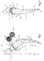
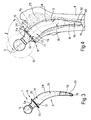
- number 1 indicates a femoral rod substantially comprising a shank 2 inserted inside the medullary cavity 3 (Fig.4) of femur 4; and a head 5 inserted inside the cavity 6 (Fig.12) of a cup 7 inserted inside the acetabular cavity 8 of the hip, as shown in Fig.12, and which may be a biequatorial cup as described in Italian utility patent n.1095649.
- rod 1 substantially comprises means 9 for transferring the physiological loads normally supported by femur 4 on to section 11 of femoral neck 10 (Fig. 4) just below the head 12 of the femur (shown by the dotted line in Fig.4).
- Means 9 consist substantially of a transversely projecting collar 13 at the top end of shank 2, of substantially the same external shape and size as neck 10 beneath head 12 (Fig. 4), and connected to head 5 by a connecting portion 5a.
- shank 2 substantially comprises a proximal or top portion 14 just below collar 13 and having a substantially straight axis a p (Fig.1); a mid portion 15 adjacent to portion 14 and having a curved axis a m blending with axis a p ; and a distal or bottom portion 16.
- proximal portion 14 tapers slightly towards the bottom end of shank 2.
- axis a p of proximal portion 14 forms an angle ⁇ of 125-130° with a line tangent to curved axis a m of mid portion 15 at end point M; and the distance "l" between point M and point P, at which axis a p intersects the bottom surface 17 of collar 13, ranges from 80 to 120 mm.
- proximal portion 14 conveniently ranges from 10 to 20 mm.
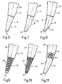
- Distal portion 16 presents a smooth surface 18; a length l d ranging from 0.33 to 0.50 of the total length of shank 2; a rounded tip 19; and may be formed as shown in any of Fig.s 6 to 11: with a straight or curved axis (Fig.s 6 and 7); with a bevel 20 on the convex side of surface 18 (Fig.8); with a number of circumferential grooves 21 (Fig. 9) or axial grooves 22 (Fig. 10) for increasing flexibility as compared with the rest of shank 2, for the reasons described later on; or from different material as compared with the rest of shank 2, e.g. composite synthetic material, in which case, it conveniently presents a projection 23 for insertion inside a cavity on mid portion 15 (Fig. 11).
- the rod according to the present invention also presents the curves shown in the Fig.2 sagittal plane perpendicular to the front plane in Fig.1.
- axis a p of proximal portion 14 forms an angle ⁇ of 10-30° with the axis of the rest of shank 2, said axes blending as shown in Fig.2; and mid portion 15 may conveniently be slightly buckled.
- Bottom surface 17 of collar 13 (Fig.1) forms an angle ⁇ of 75-90° (90° in the embodiment shown) with axis a p of proximal portion 14.
- proximal portion 14 and mid portion 15 presents means for assisting osteointegration with spongy bone 25 (Fig.4), for which purpose, surface 28 presents projections 29 (enlarged detail in Fig.1) ranging in average size from 0.5 to 1.5 mm, and conveniently also provided on bottom surface 17 of collar 13.
- surface 28 presents a 1-2.5 mm mesh net sheath 29a (enlarged detail in Fig.1).
- Proximal portion 14 conveniently presents a hydroxylapatite coating 30 (Fig.3) for assisting osteointegration of the shank surface and the spongy bone of the neck and femoral cavity; and distal portion 16 presents a sheath 31 of highly elastic, absorbable, biodegradable material for centering the tip of rod 1 during and immediately following insertion, and subsequently forming an annular gap 32 (Fig.4) between distal portion 16 and the medullary canal following absorption and breakdown of sheath 31.
- a hydroxylapatite coating 30 Fig.3
- distal portion 16 presents a sheath 31 of highly elastic, absorbable, biodegradable material for centering the tip of rod 1 during and immediately following insertion, and subsequently forming an annular gap 32 (Fig.4) between distal portion 16 and the medullary canal following absorption and breakdown of sheath 31.
- Head 5 of rod 1 is preferably not integral with shank 2, connecting portion 5a presenting a conical projection (not shown) designed to fit inside a cavity in shank 2 for enabling the formation of rods 1 featuring heads and shanks of different sizes and materials.
- Rod 1 according to the present invention is inserted as follows.
- the first stage consists in resecting head 12 of femur 4 (Fig.4) at section 11 just below head 12, which section is so selected as to preserve a portion of neck 10 with an annular portion of cortical bone 34 and the corresponding spongy bone 35.
- the axial length of said neck portion is so selected as to maintain a substantially efficient blood supply and so prevent possible necrosis of neck 10.
- the second stage consists in inserting rod 1 inside femoral cavity 3 so that collar 13 rests on section 11. Being substantially the same size as neck 10, collar 13 rests on neck 10 in such a manner as to cover the whole of section 11.
- the portions of spongy bone 35 and 25 inside neck 10 and cavity 3 are conveniently adjusted and compacted so that the inner surface of the spongy bone substantially matches the surface of shank 2, and so that, when rod 1 is inserted inside cavity 3, projections 29 (Fig.1) or net 29a penetrate gently inside the spongy bone without inducing stress in cortical bone portion 34 of neck 10.
- resection surface 11 Prior to inserting rod 1, resection surface 11 is also conveniently smoothed.
- shank 2 provide for troublefree insertion of rod 1 inside cavity 3, distal portion 16 in fact acting as a guide during insertion, and the particular configuration of the axes in the front and sagittal planes enabling rod 1 to be adapted to the shape and size of cavity 3.
- the size of shank 2 is such that only a small portion of distal portion 16, ranging between 20 and 30 mm in length, is inserted inside diaphyseal portion 36 (Fig.4). Consequently, surface 28 of the mid and proximal portions is arranged firmly contacting spongy bone 25, thus enabling effective integration of surface 28 and spongy bone 25 by virtue of projections 29 or net 29a on surface 28.
- annular gap 32 between distal portion 16 and the inner surface of femoral cavity 3 prevents any possibility of portion 16 contacting and knitting with the cortical bone and so resulting in an excessively stable, rigid connection of distal portion 16, in turn resulting in oscillation of rod 1 about said connecting portion.
- the three-dimensional design of rod 1 in particular the configuration of the axes in the front and sagittal planes, provides for strictly defining the insertion position of the rod inside the femoral cavity, and in particular the angular position of head 5 in relation to the femur.
- Fig.5 which shows a top view of the femur subsequent to insertion of rod 1
- the center of head 5 lies along a half line forming a specific angle ⁇ with a theoretical reference axis X integral with the femur, which angle matches the natural angle between the femur and hip, and, following insertion of rod 1 inside the hip, is strictly defined by virtue of the above geometric parameters.
- the rod provides for an integrated mechanical assembly involving minimum bone removal, the bone structure being preserved and closed about the rod; the shape and size of the rod are such as to preserve the metaphyseal spongy bone, and to condition the continual rearrangement occurring naturally in the spongy bone and which provides for maintaining an optimum relationship between the rod and bone; and enhanced mechanical performance of the rod and bone is achieved by providing for a system of gradually varying elasticity between the rod and the spongy and cortical bones.
- the rod according to the present invention provides for minimizing remodelling of the top portion of the femur following insertion.
- the rod according to the present invention minimizes three-dimensional relative movement between the rod and bone, and ensures maximum primary or initial stability by providing for a high degree of torsional, inward-outward rotational and vertical stability.
- torsional stability the particular configuration and inclination of the shank axes in the front and sagittal planes prevent pathological microrotation of the rod inside the femur, as occurs at times inside the diaphysis in the case of conventional prostheses, all of which in fact are subject to rotational instability by virtue of requiring removal of neck 10.
- the curvature of the rod axes and the contact surface between the rod and spongy bone and between collar 13 and surface 11 prevent the rod from rotating inwards or outwards in the front plane; which stability is also greatly enhanced by reducing the torque on head 5 in relation to cortical bone 34 of neck 10 supporting collar 13, by reducing the distance (lever arm) between head 5 and the cortical bone-rod interface (collar 13) as compared with known prostheses.
- the short length of the rod and the fact that shank 2 is inserted inside spongy bone 25, 35 provide for a system of gradually variable elasticity which, in addition to a closer physiological resemblance, provides for absorbing stress between the prosthesis and femur, in particular, shearing stress which, in the case of discontinuously variable elasticity, could result in detachment of the rod from the bone.
- the rod according to the present invention also provides for load distribution along the physiological lines of the bone, and thus for more natural performance of the bone-prosthesis system.
- the design of the rod and in particular the rough finish of rod surface 28 and collar surface 17 enable purely metaphyseal fitment of the rod, with distal portion 16 freely suspended inside medullary canal 3. This is important for preventing undesired embedding of the distal portion, which is also prevented by so designing the distal portion, as shown in any one of the embodiments in Fig.s 6 to 11, that, even in the event of minor displacement of the rod in relation to the femur, no contact occurs between the distal portion and medullary canal 3, or, at most, the distal portion rests only lightly on the canal by virtue of the high degree of elasticity of distal portion 16.
- neck 10 and the short length of the rod provide for troublefree removal, by simply removing neck 10 to expose the underlying rod portion, which is sufficient for easily extracting the remainder of the rod. This may then be replaced by a conventional rod requiring removal of neck 10.
- collar 13 may present a number of portions projecting radially from shank 2, or any other design featuring means for transferring the physiological loads normally supported by the femur on to a section of neck 10 located immediately below head 12.
- hydroxylapatite coating 30 and/or biodegradable, absorbable sheath 31 may be dispensed with, and changes made to the manner in which a stable connection is achieved between the rod and bone.
- surface 28 of proximal portion 14 and mid portion 15 may present a smooth surface finish, with a number of holes or indentations for assisting attachment and fitment of the rod to the metaphyseal spongy bone.
- the surface of proximal portion 14 may be grooved, scored or otherwise roughened for assisting integration and so achieving a stable connection of the rod and bone.
- the present invention also relates to a system enabling articulated connection of the periacetabular bone and the femur, characterized by the fact that it comprises: a femoral rod 1 substantially comprising a shank 2 inserted inside the femur; a head 5 extending axially from shank 2; and a collar 13 projecting transversely from and located at the top end of shank 2; an acetabular cup 6 fitted to the periacetabular bone, for housing head 5 of rod 1 and enabling angular oscillation of the rod in relation to the periacetabular bone; a femoral neck 10 projecting integrally from the femur, surrounding a portion of shank 2 adjacent to said top end, and designed to support said collar.
- the axial length of neck 10 is selected substantially equal to that produced by a resection effected below head 12 of the femur; and the size of collar 13, measured in directions lying in the plane defined by said resection, is substantially equal to the thickness of neck 10 measured in the same directions.
Landscapes
- Health & Medical Sciences (AREA)
- Orthopedic Medicine & Surgery (AREA)
- Cardiology (AREA)
- Oral & Maxillofacial Surgery (AREA)
- Transplantation (AREA)
- Engineering & Computer Science (AREA)
- Biomedical Technology (AREA)
- Heart & Thoracic Surgery (AREA)
- Vascular Medicine (AREA)
- Life Sciences & Earth Sciences (AREA)
- Animal Behavior & Ethology (AREA)
- General Health & Medical Sciences (AREA)
- Public Health (AREA)
- Veterinary Medicine (AREA)
- Prostheses (AREA)
Abstract
Description
- The present invention relates to a femoral rod for a complete hip prosthesis.
- Complete hip prostheses currently feature a rod consisting of a shank inserted inside the femur, and a spherical head projecting from the bone and cooperating with an acetabular cup in turn fitted to the periacetabular bone.
- To insert the rod, a resection is effected at the base of the neck to remove the head and neck of the femur, and the shank of the rod is actually forced or cemented in place inside the medullary canal. To ensure the vertical stability of the rod, the proximal or top end facing the head sometimes presents a small flange for preventing the rod from subsiding inside the femur.
- Femoral rods of the aforementioned type are normally designed to be press fitted inside the medullary canal, so as to provide for a tight fit between the rod and the cortical bone, for which purpose the spongy bone inside the medullary canal is normally removed.
- Known rods and the method whereby they are inserted present several drawbacks.
- Firstly, removal of the nondiseased neck of the femur, which is rich in spongy bone, seriously affects normal load transmission, which is extremely difficult to adapt to.
- Secondly, by virtue of the shank being press fitted tightly inside the medullary canal, the elasticity of the resulting structure varies sharply and, hence, discontinuously at the prosthesis-bone interface, thus further affecting normal load transmission, and preventing the bone from adapting to a more physiological condition wherein elasticity varies transversely in relation to the bone.
- Thirdly, in the event of failure, removal of the rod poses serious problems, due to the difficulty of separating it from the attached bone.
- Lastly, the shape and size of the distal or end portion of the shank may result in what is commonly referred to as the "tip effect" or undesired embedding of the distal portion, thus resulting in hypertrophy of the cortical bone or at any rate painful irritation of the bone, and possibly also in detachment of the rod from the bone as of the proximal or top portion of the rod.
- It is an object of the present invention to provide a rod designed to overcome the aforementioned drawbacks, while at the same time respecting normal biological and biomechanical conditions.
- According to the present invention, there is provided a femoral rod for a complete hip prosthesis, comprising a shank inserted inside the femur, and a head for the articulation of the femur; characterized by the fact that it comprises means for transferring the physiological loads normally supported by the femur on to a section of the neck immediately below the head of the femur.
- According to a preferred embodiment of the present invention, said means consist of a transversely projecting collar at the proximal or top end of the shank, and of substantially the same external shape and size as the neck below the head of the femur.
- According to the present invention, there is also provided a system enabling articulated connection of the periacetabular bone and the femur, characterized by the fact that it comprises:
a femoral rod substantially comprising a shank inserted inside the femur; a head extending axially from said shank; and a collar projecting transversely from and located at the proximal end of said shank;
an acetabular cup fitted to the periacetabular bone, for housing and enabling angular oscillation of the rod in relation to the periacetabular bone;
a femoral neck projecting integrally from the femur, surrounding a portion of said shank adjacent to said proximal end, and designed to support said collar of said rod;
the axial length of the femoral neck being substantially equal to that produced by a resection effected below the head of the femur;
the size of said collar of said rod, measured in directions lying in the plane defined by said resection, being substantially equal to the thickness of the femoral neck measured in the same directions. - In other words, insertion of the shank of the rod according to the present invention requires that the neck of the femur be retained, thus enabling the spongy bone inside the neck and the proximal metaphysis to be employed for cushioning load and so producing a variably elastic structure. The collar of the rod provides for transmitting load physiologically on to the neck of the femur, and for arresting potential longitudinal movement of the shank as described in detail later on.
- Moreover, by virtue of the shape and size of the rod as described later on, the rod according to the present invention provides for transmitting load along the lines of force in the physiological direction, while the extremely short length of the rod provides for reliable, troublefree insertion, and perfect centering of the bottom end or distal portion of the rod inside the femoral cavity. Finally, in the event of failure of the prosthesis according to the present invention, the head may be resected for inserting a conventional rod, in which case, removal and replacement of the rod according to the present invention are greatly facilitated.
- A preferred non-limiting embodiment of the present invention will be described by way of example with reference to the accompanying drawings, in which:
- Fig.1 shows a front view of the rod according to the present invention;
- Fig.2 shows a side view of the Fig.1 rod;
- Fig.3 shows a further schematic front view of the rod;
- Fig.4 shows a view of the rod as inserted inside the femur;
- Fig.5 shows a top view of the Fig.4 rod-femur assembly;
- Fig.s 6 to 11 show design variations of the end or distal portion of the rod;
- Fig.12 shows a schematic view of the rod-acetabular cup connection of a complete hip prosthesis.
- With reference to Fig.s 1 and 2, number 1 indicates a femoral rod substantially comprising a
shank 2 inserted inside the medullary cavity 3 (Fig.4) of femur 4; and ahead 5 inserted inside the cavity 6 (Fig.12) of a cup 7 inserted inside the acetabular cavity 8 of the hip, as shown in Fig.12, and which may be a biequatorial cup as described in Italian utility patent n.1095649. - According to the present invention, rod 1 substantially comprises means 9 for transferring the physiological loads normally supported by femur 4 on to
section 11 of femoral neck 10 (Fig. 4) just below thehead 12 of the femur (shown by the dotted line in Fig.4). -
Means 9 consist substantially of a transversely projectingcollar 13 at the top end ofshank 2, of substantially the same external shape and size asneck 10 beneath head 12 (Fig. 4), and connected tohead 5 by a connectingportion 5a. - According to the present invention,
shank 2 substantially comprises a proximal ortop portion 14 just belowcollar 13 and having a substantially straight axis ap (Fig.1); amid portion 15 adjacent toportion 14 and having a curved axis am blending with axis ap; and a distal orbottom portion 16. - Conveniently, though not necessarily,
proximal portion 14 tapers slightly towards the bottom end ofshank 2. - With reference to the front view shown in Fig.1, axis ap of
proximal portion 14 forms an angle α of 125-130° with a line tangent to curved axis am ofmid portion 15 at end point M; and the distance "l" between point M and point P, at which axis ap intersects thebottom surface 17 ofcollar 13, ranges from 80 to 120 mm. - The length of
proximal portion 14 conveniently ranges from 10 to 20 mm. -
Distal portion 16 presents asmooth surface 18; a length ld ranging from 0.33 to 0.50 of the total length ofshank 2; arounded tip 19; and may be formed as shown in any of Fig.s 6 to 11: with a straight or curved axis (Fig.s 6 and 7); with abevel 20 on the convex side of surface 18 (Fig.8); with a number of circumferential grooves 21 (Fig. 9) or axial grooves 22 (Fig. 10) for increasing flexibility as compared with the rest ofshank 2, for the reasons described later on; or from different material as compared with the rest ofshank 2, e.g. composite synthetic material, in which case, it conveniently presents aprojection 23 for insertion inside a cavity on mid portion 15 (Fig. 11). - The rod according to the present invention also presents the curves shown in the Fig.2 sagittal plane perpendicular to the front plane in Fig.1. In the Fig.2 plane, axis ap of
proximal portion 14 forms an angle β of 10-30° with the axis of the rest ofshank 2, said axes blending as shown in Fig.2; andmid portion 15 may conveniently be slightly buckled. -
Bottom surface 17 of collar 13 (Fig.1) forms an angle τ of 75-90° (90° in the embodiment shown) with axis ap ofproximal portion 14. -
Surface 28 externally definingproximal portion 14 and mid portion 15 (Fig.s 1 and 2) presents means for assisting osteointegration with spongy bone 25 (Fig.4), for which purpose,surface 28 presents projections 29 (enlarged detail in Fig.1) ranging in average size from 0.5 to 1.5 mm, and conveniently also provided onbottom surface 17 ofcollar 13. - Alternatively,
surface 28 presents a 1-2.5 mm mesh net sheath 29a (enlarged detail in Fig.1). -
Proximal portion 14 conveniently presents a hydroxylapatite coating 30 (Fig.3) for assisting osteointegration of the shank surface and the spongy bone of the neck and femoral cavity; anddistal portion 16 presents asheath 31 of highly elastic, absorbable, biodegradable material for centering the tip of rod 1 during and immediately following insertion, and subsequently forming an annular gap 32 (Fig.4) betweendistal portion 16 and the medullary canal following absorption and breakdown ofsheath 31. -
Head 5 of rod 1 is preferably not integral withshank 2, connectingportion 5a presenting a conical projection (not shown) designed to fit inside a cavity inshank 2 for enabling the formation of rods 1 featuring heads and shanks of different sizes and materials. - Rod 1 according to the present invention is inserted as follows.
- The first stage consists in resecting
head 12 of femur 4 (Fig.4) atsection 11 just belowhead 12, which section is so selected as to preserve a portion ofneck 10 with an annular portion ofcortical bone 34 and the correspondingspongy bone 35. The axial length of said neck portion is so selected as to maintain a substantially efficient blood supply and so prevent possible necrosis ofneck 10. - The second stage consists in inserting rod 1 inside
femoral cavity 3 so thatcollar 13 rests onsection 11. Being substantially the same size asneck 10,collar 13 rests onneck 10 in such a manner as to cover the whole ofsection 11. - Following resection of
head 12 in said first stage, the portions ofspongy bone neck 10 andcavity 3 are conveniently adjusted and compacted so that the inner surface of the spongy bone substantially matches the surface ofshank 2, and so that, when rod 1 is inserted insidecavity 3, projections 29 (Fig.1) or net 29a penetrate gently inside the spongy bone without inducing stress incortical bone portion 34 ofneck 10. - Prior to inserting rod 1,
resection surface 11 is also conveniently smoothed. - The shape and size of
shank 2 provide for troublefree insertion of rod 1 insidecavity 3,distal portion 16 in fact acting as a guide during insertion, and the particular configuration of the axes in the front and sagittal planes enabling rod 1 to be adapted to the shape and size ofcavity 3. Once rod 1 is inserted fully insidecavity 3, withcollar 13 resting onsurface 11, the size ofshank 2 is such that only a small portion ofdistal portion 16, ranging between 20 and 30 mm in length, is inserted inside diaphyseal portion 36 (Fig.4). Consequently,surface 28 of the mid and proximal portions is arranged firmly contactingspongy bone 25, thus enabling effective integration ofsurface 28 andspongy bone 25 by virtue ofprojections 29 or net 29a onsurface 28. - Moreover,
annular gap 32 betweendistal portion 16 and the inner surface offemoral cavity 3 prevents any possibility ofportion 16 contacting and knitting with the cortical bone and so resulting in an excessively stable, rigid connection ofdistal portion 16, in turn resulting in oscillation of rod 1 about said connecting portion. - The three-dimensional design of rod 1, in particular the configuration of the axes in the front and sagittal planes, provides for strictly defining the insertion position of the rod inside the femoral cavity, and in particular the angular position of
head 5 in relation to the femur. As shown in Fig.5, which shows a top view of the femur subsequent to insertion of rod 1, the center ofhead 5 lies along a half line forming a specific angle δ with a theoretical reference axis X integral with the femur, which angle matches the natural angle between the femur and hip, and, following insertion of rod 1 inside the hip, is strictly defined by virtue of the above geometric parameters. - The advantages of rod 1 according to the present invention will be clear from the foregoing description.
- In particular, it provides for an integrated mechanical assembly involving minimum bone removal, the bone structure being preserved and closed about the rod; the shape and size of the rod are such as to preserve the metaphyseal spongy bone, and to condition the continual rearrangement occurring naturally in the spongy bone and which provides for maintaining an optimum relationship between the rod and bone; and enhanced mechanical performance of the rod and bone is achieved by providing for a system of gradually varying elasticity between the rod and the spongy and cortical bones.
- Such advantages are achieved by virtue of
collar 13 resting on the entire surface ofsection 11 ofneck 10, and by virtue of the shape, size and surface finish ofcollar 13 and the rod, which are such as to occupy the whole of and mate with the inner surface ofneck 10. The resistance and rigidity ofneck 10, which is preserved entirely even after removal ofhead 12, enable unique proximal fitment of rod 1 as compared with known rods, which, being fitted to the metaphyseal portion of the femur as opposed to the neck, provide for transmitting load transversely along the rod at the metaphyseal spongy bone and diaphyseal cortical bone. - The rod according to the present invention provides for minimizing remodelling of the top portion of the femur following insertion.
- By virtue of mating perfectly with the bone, the rod according to the present invention minimizes three-dimensional relative movement between the rod and bone, and ensures maximum primary or initial stability by providing for a high degree of torsional, inward-outward rotational and vertical stability. As regards torsional stability, the particular configuration and inclination of the shank axes in the front and sagittal planes prevent pathological microrotation of the rod inside the femur, as occurs at times inside the diaphysis in the case of conventional prostheses, all of which in fact are subject to rotational instability by virtue of requiring removal of
neck 10. - As regards inward-outward rotational stability, the curvature of the rod axes and the contact surface between the rod and spongy bone and between
collar 13 andsurface 11 prevent the rod from rotating inwards or outwards in the front plane; which stability is also greatly enhanced by reducing the torque onhead 5 in relation tocortical bone 34 ofneck 10 supportingcollar 13, by reducing the distance (lever arm) betweenhead 5 and the cortical bone-rod interface (collar 13) as compared with known prostheses. - Vertical stability, on the other hand, is assured by
collar 13 resting oncortical bone 34, which acts in fact as a ring for preventing the rod from subsiding inside the bone; and by the shape and characteristic angles of the rod. - In view of the high degree of initial stability provided for by the rod according to the present invention, this need no longer be press-fitted but simply inserted inside
spongy bone - Moreover, the short length of the rod and the fact that
shank 2 is inserted insidespongy bone - The rod according to the present invention also provides for load distribution along the physiological lines of the bone, and thus for more natural performance of the bone-prosthesis system.
- The design of the rod and in particular the rough finish of
rod surface 28 andcollar surface 17 enable purely metaphyseal fitment of the rod, withdistal portion 16 freely suspended insidemedullary canal 3. This is important for preventing undesired embedding of the distal portion, which is also prevented by so designing the distal portion, as shown in any one of the embodiments in Fig.s 6 to 11, that, even in the event of minor displacement of the rod in relation to the femur, no contact occurs between the distal portion andmedullary canal 3, or, at most, the distal portion rests only lightly on the canal by virtue of the high degree of elasticity ofdistal portion 16. - As already stated, by virtue of the short length of the rod according to the present invention, only a short portion of
distal portion 16 is inserted insidediaphyseal portion 36, so that the boundary section between the femur-prosthesis structure and the femur itself is located much higher (40-80 mm) as compared with conventional prostheses, and, what is more, in a portion of the bone having a highly resistant and undoubtedly more elastic and extensive section, thus greatly reducing discomfort, as compared with known prostheses, following insertion of the rod. - In the event of failure of the prosthesis,
neck 10 and the short length of the rod provide for troublefree removal, by simply removingneck 10 to expose the underlying rod portion, which is sufficient for easily extracting the remainder of the rod. This may then be replaced by a conventional rod requiring removal ofneck 10. - To those skilled in the art it will be clear that changes may be made to the rod as described and illustrated herein without, however, departing from the scope of the present invention.
- In particular, instead of being formed whole as described herein,
collar 13 may present a number of portions projecting radially fromshank 2, or any other design featuring means for transferring the physiological loads normally supported by the femur on to a section ofneck 10 located immediately belowhead 12. - Also,
hydroxylapatite coating 30 and/or biodegradable,absorbable sheath 31 may be dispensed with, and changes made to the manner in which a stable connection is achieved between the rod and bone. For example, instead of a rough surface finish,surface 28 ofproximal portion 14 andmid portion 15 may present a smooth surface finish, with a number of holes or indentations for assisting attachment and fitment of the rod to the metaphyseal spongy bone. Alternatively, the surface ofproximal portion 14 may be grooved, scored or otherwise roughened for assisting integration and so achieving a stable connection of the rod and bone. - The present invention also relates to a system enabling articulated connection of the periacetabular bone and the femur, characterized by the fact that it comprises:
a femoral rod 1 substantially comprising ashank 2 inserted inside the femur; ahead 5 extending axially fromshank 2; and acollar 13 projecting transversely from and located at the top end ofshank 2;
anacetabular cup 6 fitted to the periacetabular bone, forhousing head 5 of rod 1 and enabling angular oscillation of the rod in relation to the periacetabular bone;
afemoral neck 10 projecting integrally from the femur, surrounding a portion ofshank 2 adjacent to said top end, and designed to support said collar. - In the above system, the axial length of
neck 10 is selected substantially equal to that produced by a resection effected belowhead 12 of the femur; and the size ofcollar 13, measured in directions lying in the plane defined by said resection, is substantially equal to the thickness ofneck 10 measured in the same directions.
Claims (25)
- A femoral rod (1) for a complete hip prosthesis, comprising a shank (2) inserted inside the femur (4), and a head (5) for the articulation of the femur (4); characterized by the fact that it comprises means (9) for transferring the physiological loads normally supported by the femur (4) on to a section (11) of the neck (10) immediately below the head of the femur.
- A rod as claimed in Claim 1, characterized by the fact that said means (9) consist of a transversely projecting collar (13) at the top end of said shank (2), of substantially the same external shape and size as the neck (10) below the head of the femur.
- A rod as claimed in Claim 1 or 2, characterized by the fact that said shank (2) comprises a proximal or top portion (14) immediately below said collar (13) and having a substantially straight axis ap; a mid portion (15) adjacent to said proximal portion (14) and having a curved axis am blending with said axis ap; and a distal or bottom portion (16).
- A rod as claimed in Claim 3, characterized by the fact that said proximal portion (14) tapers slightly towards the bottom end of said shank (2).
- A rod as claimed in one of the foregoing Claims, characterized by the fact that, in the front plane, said axis ap of said proximal portion (14) forms an angle of 125-130° with a line tangent to end point M of said curved axis am of said mid portion (15); and the distance between said point M and the point P at which said straight axis ap intersects the bottom surface (17) of said collar (13) ranges from 80 to 120 mm.
- A rod as claimed in one of the foregoing Claims, characterized by the fact that said proximal portion (14) of said shank (2) presents a length of 10 to 20 mm.
- A rod as claimed in one of the foregoing Claims, characterized by the fact that the surface (18) of said distal portion (16) is smooth; said distal portion (16) presenting a length ranging from 0.33 to 0.50 of the total length of said shank (2) and having a rounded tip (19).
- A rod as claimed in Claim 7, characterized by the fact that the axis of said distal portion (16) is straight.
- A rod as claimed in one of the foregoing Claims from 1 to 6, characterized by the fact that the axis of said distal portion (16) is curved.
- A rod as claimed in Claim 9, characterized by the fact that said distal portion (16) presents a bevel (20) on the portion of said surface (18) facing the convex side of said shank (2).
- A rod as claimed in one of the foregoing Claims, characterized by the fact that the flexibility of said distal portion (16) is greater than that of the rest of said shank (2).
- A rod as claimed in Claim 10, characterized by the fact that said distal portion (16) presents radial cavities (21).
- A rod as claimed in Claim 11, characterized by the fact that said distal portion (16) presents longitudinal grooves (22).
- A rod as claimed in Claim 11, characterized by the fact that said distal portion (16) is made of different material from the rest of said shank (2).
- A rod as claimed in one of the foregoing Claims from 7 to 14, characterized by the fact that said distal portion (16) is made of composite synthetic material.
- A rod as claimed in one of the foregoing Claims, characterized by the fact that, in the sagittal plane perpendicular to said front plane, the axis of said proximal portion (14) of said shank (2) forms an angle of 10-30° with the axis of the remaining portion of said shank (2); said two axes blending with each other.
- A rod as claimed in one of the foregoing Claims, characterized by the fact that the bottom surface (17) of said collar (13) forms an angle of 75-90° with said axis ap of said proximal portion (14) of said shank (2).
- A rod as claimed in one of the foregoing Claims, characterized by the fact that, with the exception of said surface (18) of said distal portion (16), said surface (28) of said shank (2) presents means for assisting osteointegration with the spongy bone (25, 35) of the femur (4).
- A rod as claimed in Claim 17, characterized by the fact that, with the exception of said surface (18) of said distal portion (16), said surface (28) of said shank (2) presents projections (29) ranging in average size from 0.5 to 1.5 mm.
- A rod as claimed in Claim 18, characterized by the fact that said projections (29) are also provided on said bottom surface (17) of said collar (13).
- A rod as claimed in Claim 18, characterized by the fact that, with the exception of said surface (18) of said distal portion (16), said surface (28) of said shank (2) presents a 1-2.5 mm mesh net sheath.
- A rod as claimed in any one of the foregoing Claims, characterized by the fact that said distal portion (16) of said shank (2) presents a sheath (31) of biodegradable, absorbable material.
- A rod as claimed in any one of the foregoing Claims, characterized by the fact that said proximal portion (14) presents a coating (30) of hydroxylapatite.
- A system enabling articulated connection of the periacetabular bone and the femur, characterized by the fact that it comprises:
a femoral rod (1) substantially comprising a shank (2) inserted inside the femur (4); a head (5) extending axially from said shank (2); and a collar (13) projecting transversely from and located at the top end of said shank (2);
an acetabular cup (6) fitted to the periacetabular bone, for housing said head (5) of said rod (1) and enabling angular oscillation of the rod (1) in relation to the periacetabular bone;
a femoral neck (10) projecting integrally from the femur (4), surrounding a portion of said shank (2) adjacent to said top end, and designed to support said collar (13) of said rod (1);
the axial length of the femoral neck (10) being substantially equal to that produced by a resection effected below the head of the femur;
the size of said collar (13) of said rod (1), measured in directions lying in the plane defined by said resection, being substantially equal to the thickness of the femoral neck (10) measured in the same directions. - A system as claimed in Claim 24, characterized by the fact that said rod (1) presents the characteristics claimed in Claims 1 to 23.
Applications Claiming Priority (2)
| Application Number | Priority Date | Filing Date | Title |
|---|---|---|---|
| ITTO920634A IT1256891B (en) | 1992-07-24 | 1992-07-24 | FEMORAL STEM FOR TOTAL HIP PROSTHESIS |
| ITTO920634 | 1992-07-24 |
Publications (2)
| Publication Number | Publication Date |
|---|---|
| EP0579868A2 true EP0579868A2 (en) | 1994-01-26 |
| EP0579868A3 EP0579868A3 (en) | 1995-11-02 |
Family
ID=11410632
Family Applications (1)
| Application Number | Title | Priority Date | Filing Date |
|---|---|---|---|
| EP92120122A Withdrawn EP0579868A3 (en) | 1992-07-24 | 1992-11-25 | Femoral rod for a complete hip prosthesis |
Country Status (2)
| Country | Link |
|---|---|
| EP (1) | EP0579868A3 (en) |
| IT (1) | IT1256891B (en) |
Cited By (88)
| Publication number | Priority date | Publication date | Assignee | Title |
|---|---|---|---|---|
| WO1998042279A1 (en) * | 1997-03-26 | 1998-10-01 | Waldemar Link (Gmbh & Co.) | Hip joint endoprosthesis |
| EP0878176A3 (en) * | 1997-05-16 | 1999-07-14 | ESKA Implants GmbH & Co. | Femoral neck endoprosthesis for an artificial hip joint |
| US6120544A (en) * | 1997-05-16 | 2000-09-19 | Eska Implants Gmbh & Co. | Femur endoprosthesis for articial hip joint |
| GB2388321A (en) * | 2002-03-26 | 2003-11-12 | Derek James Wallace Mcminn | Hip Joint Prosthesis |
| DE102004051431B3 (en) * | 2004-10-19 | 2006-06-01 | Eska Implants Gmbh & Co. | Meta-diaphysiar end prothesis for artificial hip joint has support whose outside edge is covered with a meshed net structure with smooth surface at distal end for laying on femur |
| WO2009053690A3 (en) * | 2007-10-22 | 2009-06-11 | Tj Smith & Nephew Ltd | Joint prosthesis |
| EP1996124A4 (en) * | 2006-03-21 | 2009-12-30 | Tornier Inc | FEMORAL AND HUMERAL ROD GEOMETRY AND IMPLANTATION TECHNIQUES FOR ORTHOPEDIC JOINT RECONSTRUCTION |
| US8070752B2 (en) | 2006-02-27 | 2011-12-06 | Biomet Manufacturing Corp. | Patient specific alignment guide and inter-operative adjustment |
| US8092465B2 (en) | 2006-06-09 | 2012-01-10 | Biomet Manufacturing Corp. | Patient specific knee alignment guide and associated method |
| US8133234B2 (en) | 2006-02-27 | 2012-03-13 | Biomet Manufacturing Corp. | Patient specific acetabular guide and method |
| US8170641B2 (en) | 2009-02-20 | 2012-05-01 | Biomet Manufacturing Corp. | Method of imaging an extremity of a patient |
| US8241293B2 (en) | 2006-02-27 | 2012-08-14 | Biomet Manufacturing Corp. | Patient specific high tibia osteotomy |
| US8265949B2 (en) | 2007-09-27 | 2012-09-11 | Depuy Products, Inc. | Customized patient surgical plan |
| US8282646B2 (en) | 2006-02-27 | 2012-10-09 | Biomet Manufacturing Corp. | Patient specific knee alignment guide and associated method |
| US8298237B2 (en) | 2006-06-09 | 2012-10-30 | Biomet Manufacturing Corp. | Patient-specific alignment guide for multiple incisions |
| US8343159B2 (en) | 2007-09-30 | 2013-01-01 | Depuy Products, Inc. | Orthopaedic bone saw and method of use thereof |
| US8357111B2 (en) | 2007-09-30 | 2013-01-22 | Depuy Products, Inc. | Method and system for designing patient-specific orthopaedic surgical instruments |
| US8377066B2 (en) | 2006-02-27 | 2013-02-19 | Biomet Manufacturing Corp. | Patient-specific elbow guides and associated methods |
| US8407067B2 (en) | 2007-04-17 | 2013-03-26 | Biomet Manufacturing Corp. | Method and apparatus for manufacturing an implant |
| US8473305B2 (en) | 2007-04-17 | 2013-06-25 | Biomet Manufacturing Corp. | Method and apparatus for manufacturing an implant |
| US8486150B2 (en) | 2007-04-17 | 2013-07-16 | Biomet Manufacturing Corp. | Patient-modified implant |
| US8532807B2 (en) | 2011-06-06 | 2013-09-10 | Biomet Manufacturing, Llc | Pre-operative planning and manufacturing method for orthopedic procedure |
| US8535387B2 (en) | 2006-02-27 | 2013-09-17 | Biomet Manufacturing, Llc | Patient-specific tools and implants |
| US8568487B2 (en) | 2006-02-27 | 2013-10-29 | Biomet Manufacturing, Llc | Patient-specific hip joint devices |
| US8591516B2 (en) | 2006-02-27 | 2013-11-26 | Biomet Manufacturing, Llc | Patient-specific orthopedic instruments |
| US8597365B2 (en) | 2011-08-04 | 2013-12-03 | Biomet Manufacturing, Llc | Patient-specific pelvic implants for acetabular reconstruction |
| US8603180B2 (en) | 2006-02-27 | 2013-12-10 | Biomet Manufacturing, Llc | Patient-specific acetabular alignment guides |
| US8608748B2 (en) | 2006-02-27 | 2013-12-17 | Biomet Manufacturing, Llc | Patient specific guides |
| US8608749B2 (en) | 2006-02-27 | 2013-12-17 | Biomet Manufacturing, Llc | Patient-specific acetabular guides and associated instruments |
| US8632547B2 (en) | 2010-02-26 | 2014-01-21 | Biomet Sports Medicine, Llc | Patient-specific osteotomy devices and methods |
| US8668700B2 (en) | 2011-04-29 | 2014-03-11 | Biomet Manufacturing, Llc | Patient-specific convertible guides |
| US8715289B2 (en) | 2011-04-15 | 2014-05-06 | Biomet Manufacturing, Llc | Patient-specific numerically controlled instrument |
| US8764760B2 (en) | 2011-07-01 | 2014-07-01 | Biomet Manufacturing, Llc | Patient-specific bone-cutting guidance instruments and methods |
| US8858561B2 (en) | 2006-06-09 | 2014-10-14 | Blomet Manufacturing, LLC | Patient-specific alignment guide |
| US8864769B2 (en) | 2006-02-27 | 2014-10-21 | Biomet Manufacturing, Llc | Alignment guides with patient-specific anchoring elements |
| US8956364B2 (en) | 2011-04-29 | 2015-02-17 | Biomet Manufacturing, Llc | Patient-specific partial knee guides and other instruments |
| US8992531B2 (en) | 2011-12-16 | 2015-03-31 | Chow Ip, Llc | Prosthetic femoral stem for use in high impact hip replacement |
| US9060788B2 (en) | 2012-12-11 | 2015-06-23 | Biomet Manufacturing, Llc | Patient-specific acetabular guide for anterior approach |
| US9066734B2 (en) | 2011-08-31 | 2015-06-30 | Biomet Manufacturing, Llc | Patient-specific sacroiliac guides and associated methods |
| US9066727B2 (en) | 2010-03-04 | 2015-06-30 | Materialise Nv | Patient-specific computed tomography guides |
| US9084618B2 (en) | 2011-06-13 | 2015-07-21 | Biomet Manufacturing, Llc | Drill guides for confirming alignment of patient-specific alignment guides |
| US9113971B2 (en) | 2006-02-27 | 2015-08-25 | Biomet Manufacturing, Llc | Femoral acetabular impingement guide |
| US9173661B2 (en) | 2006-02-27 | 2015-11-03 | Biomet Manufacturing, Llc | Patient specific alignment guide with cutting surface and laser indicator |
| US9204977B2 (en) | 2012-12-11 | 2015-12-08 | Biomet Manufacturing, Llc | Patient-specific acetabular guide for anterior approach |
| US9237950B2 (en) | 2012-02-02 | 2016-01-19 | Biomet Manufacturing, Llc | Implant with patient-specific porous structure |
| US9241745B2 (en) | 2011-03-07 | 2016-01-26 | Biomet Manufacturing, Llc | Patient-specific femoral version guide |
| US9271744B2 (en) | 2010-09-29 | 2016-03-01 | Biomet Manufacturing, Llc | Patient-specific guide for partial acetabular socket replacement |
| US9289253B2 (en) | 2006-02-27 | 2016-03-22 | Biomet Manufacturing, Llc | Patient-specific shoulder guide |
| US9295497B2 (en) | 2011-08-31 | 2016-03-29 | Biomet Manufacturing, Llc | Patient-specific sacroiliac and pedicle guides |
| US9301812B2 (en) | 2011-10-27 | 2016-04-05 | Biomet Manufacturing, Llc | Methods for patient-specific shoulder arthroplasty |
| US9301765B2 (en) | 2011-12-16 | 2016-04-05 | Chow Ip, Llc | Prosthetic femoral stem for use in high offset hip replacement |
| US9339278B2 (en) | 2006-02-27 | 2016-05-17 | Biomet Manufacturing, Llc | Patient-specific acetabular guides and associated instruments |
| US9345548B2 (en) | 2006-02-27 | 2016-05-24 | Biomet Manufacturing, Llc | Patient-specific pre-operative planning |
| US9351743B2 (en) | 2011-10-27 | 2016-05-31 | Biomet Manufacturing, Llc | Patient-specific glenoid guides |
| US9386993B2 (en) | 2011-09-29 | 2016-07-12 | Biomet Manufacturing, Llc | Patient-specific femoroacetabular impingement instruments and methods |
| US9393028B2 (en) | 2009-08-13 | 2016-07-19 | Biomet Manufacturing, Llc | Device for the resection of bones, method for producing such a device, endoprosthesis suited for this purpose and method for producing such an endoprosthesis |
| US9408616B2 (en) | 2014-05-12 | 2016-08-09 | Biomet Manufacturing, Llc | Humeral cut guide |
| US9451973B2 (en) | 2011-10-27 | 2016-09-27 | Biomet Manufacturing, Llc | Patient specific glenoid guide |
| US9498233B2 (en) | 2013-03-13 | 2016-11-22 | Biomet Manufacturing, Llc. | Universal acetabular guide and associated hardware |
| US9517145B2 (en) | 2013-03-15 | 2016-12-13 | Biomet Manufacturing, Llc | Guide alignment system and method |
| US9554910B2 (en) | 2011-10-27 | 2017-01-31 | Biomet Manufacturing, Llc | Patient-specific glenoid guide and implants |
| US9561040B2 (en) | 2014-06-03 | 2017-02-07 | Biomet Manufacturing, Llc | Patient-specific glenoid depth control |
| US9579107B2 (en) | 2013-03-12 | 2017-02-28 | Biomet Manufacturing, Llc | Multi-point fit for patient specific guide |
| WO2017054053A1 (en) * | 2015-09-30 | 2017-04-06 | Kirwan David Phillip | Hip prosthesis |
| US9675400B2 (en) | 2011-04-19 | 2017-06-13 | Biomet Manufacturing, Llc | Patient-specific fracture fixation instrumentation and method |
| US9795399B2 (en) | 2006-06-09 | 2017-10-24 | Biomet Manufacturing, Llc | Patient-specific knee alignment guide and associated method |
| US9820868B2 (en) | 2015-03-30 | 2017-11-21 | Biomet Manufacturing, Llc | Method and apparatus for a pin apparatus |
| US9826994B2 (en) | 2014-09-29 | 2017-11-28 | Biomet Manufacturing, Llc | Adjustable glenoid pin insertion guide |
| US9826981B2 (en) | 2013-03-13 | 2017-11-28 | Biomet Manufacturing, Llc | Tangential fit of patient-specific guides |
| US9833245B2 (en) | 2014-09-29 | 2017-12-05 | Biomet Sports Medicine, Llc | Tibial tubercule osteotomy |
| US9839438B2 (en) | 2013-03-11 | 2017-12-12 | Biomet Manufacturing, Llc | Patient-specific glenoid guide with a reusable guide holder |
| US9839436B2 (en) | 2014-06-03 | 2017-12-12 | Biomet Manufacturing, Llc | Patient-specific glenoid depth control |
| US9907659B2 (en) | 2007-04-17 | 2018-03-06 | Biomet Manufacturing, Llc | Method and apparatus for manufacturing an implant |
| US9918740B2 (en) | 2006-02-27 | 2018-03-20 | Biomet Manufacturing, Llc | Backup surgical instrument system and method |
| US9968376B2 (en) | 2010-11-29 | 2018-05-15 | Biomet Manufacturing, Llc | Patient-specific orthopedic instruments |
| US10226262B2 (en) | 2015-06-25 | 2019-03-12 | Biomet Manufacturing, Llc | Patient-specific humeral guide designs |
| US10278711B2 (en) | 2006-02-27 | 2019-05-07 | Biomet Manufacturing, Llc | Patient-specific femoral guide |
| US10282488B2 (en) | 2014-04-25 | 2019-05-07 | Biomet Manufacturing, Llc | HTO guide with optional guided ACL/PCL tunnels |
| US10492798B2 (en) | 2011-07-01 | 2019-12-03 | Biomet Manufacturing, Llc | Backup kit for a patient-specific arthroplasty kit assembly |
| US10568647B2 (en) | 2015-06-25 | 2020-02-25 | Biomet Manufacturing, Llc | Patient-specific humeral guide designs |
| US10603179B2 (en) | 2006-02-27 | 2020-03-31 | Biomet Manufacturing, Llc | Patient-specific augments |
| US10722310B2 (en) | 2017-03-13 | 2020-07-28 | Zimmer Biomet CMF and Thoracic, LLC | Virtual surgery planning system and method |
| US11051829B2 (en) | 2018-06-26 | 2021-07-06 | DePuy Synthes Products, Inc. | Customized patient-specific orthopaedic surgical instrument |
| US11179165B2 (en) | 2013-10-21 | 2021-11-23 | Biomet Manufacturing, Llc | Ligament guide registration |
| US20220117745A1 (en) * | 2020-10-16 | 2022-04-21 | Howmedica Osteonics Corp. | Self-Broaching Neck Preserving Hip Stem |
| US11419618B2 (en) | 2011-10-27 | 2022-08-23 | Biomet Manufacturing, Llc | Patient-specific glenoid guides |
| CN115040292A (en) * | 2021-05-21 | 2022-09-13 | 天津理工大学 | Bone-prosthesis interface relative displacement device |
| CN115531046A (en) * | 2020-10-12 | 2022-12-30 | 王建平 | A semi-custom combined prosthesis for hip femoral tumor |
Family Cites Families (1)
| Publication number | Priority date | Publication date | Assignee | Title |
|---|---|---|---|---|
| FR2021313A5 (en) * | 1969-09-18 | 1970-07-17 | Ficat Raymond |
-
1992
- 1992-07-24 IT ITTO920634A patent/IT1256891B/en active IP Right Grant
- 1992-11-25 EP EP92120122A patent/EP0579868A3/en not_active Withdrawn
Cited By (180)
| Publication number | Priority date | Publication date | Assignee | Title |
|---|---|---|---|---|
| US6224634B1 (en) | 1997-03-26 | 2001-05-01 | Waldemar Link (Gmbh & Co.) | Hip-joint endoprosthesis |
| WO1998042279A1 (en) * | 1997-03-26 | 1998-10-01 | Waldemar Link (Gmbh & Co.) | Hip joint endoprosthesis |
| EP0878176A3 (en) * | 1997-05-16 | 1999-07-14 | ESKA Implants GmbH & Co. | Femoral neck endoprosthesis for an artificial hip joint |
| US6120544A (en) * | 1997-05-16 | 2000-09-19 | Eska Implants Gmbh & Co. | Femur endoprosthesis for articial hip joint |
| US8177852B2 (en) | 2002-03-26 | 2012-05-15 | Smith & Nephew, Inc. | Hip joint prosthesis |
| GB2388321A (en) * | 2002-03-26 | 2003-11-12 | Derek James Wallace Mcminn | Hip Joint Prosthesis |
| GB2388321B (en) * | 2002-03-26 | 2006-04-12 | Derek James Wallace Mcminn | Hip joint prosthesis |
| US8808391B2 (en) | 2002-03-26 | 2014-08-19 | T.J. Smith & Nephew, Limited | Hip joint prosthesis |
| US7879106B2 (en) | 2002-03-26 | 2011-02-01 | Smith & Nephew, Inc. | Hip joint prosthesis |
| DE102004051431B3 (en) * | 2004-10-19 | 2006-06-01 | Eska Implants Gmbh & Co. | Meta-diaphysiar end prothesis for artificial hip joint has support whose outside edge is covered with a meshed net structure with smooth surface at distal end for laying on femur |
| US8377066B2 (en) | 2006-02-27 | 2013-02-19 | Biomet Manufacturing Corp. | Patient-specific elbow guides and associated methods |
| US9539013B2 (en) | 2006-02-27 | 2017-01-10 | Biomet Manufacturing, Llc | Patient-specific elbow guides and associated methods |
| US8133234B2 (en) | 2006-02-27 | 2012-03-13 | Biomet Manufacturing Corp. | Patient specific acetabular guide and method |
| US10743937B2 (en) | 2006-02-27 | 2020-08-18 | Biomet Manufacturing, Llc | Backup surgical instrument system and method |
| US8070752B2 (en) | 2006-02-27 | 2011-12-06 | Biomet Manufacturing Corp. | Patient specific alignment guide and inter-operative adjustment |
| US8241293B2 (en) | 2006-02-27 | 2012-08-14 | Biomet Manufacturing Corp. | Patient specific high tibia osteotomy |
| US10603179B2 (en) | 2006-02-27 | 2020-03-31 | Biomet Manufacturing, Llc | Patient-specific augments |
| US8282646B2 (en) | 2006-02-27 | 2012-10-09 | Biomet Manufacturing Corp. | Patient specific knee alignment guide and associated method |
| US10507029B2 (en) | 2006-02-27 | 2019-12-17 | Biomet Manufacturing, Llc | Patient-specific acetabular guides and associated instruments |
| US10426492B2 (en) | 2006-02-27 | 2019-10-01 | Biomet Manufacturing, Llc | Patient specific alignment guide with cutting surface and laser indicator |
| US10390845B2 (en) | 2006-02-27 | 2019-08-27 | Biomet Manufacturing, Llc | Patient-specific shoulder guide |
| US10278711B2 (en) | 2006-02-27 | 2019-05-07 | Biomet Manufacturing, Llc | Patient-specific femoral guide |
| US10206695B2 (en) | 2006-02-27 | 2019-02-19 | Biomet Manufacturing, Llc | Femoral acetabular impingement guide |
| US9918740B2 (en) | 2006-02-27 | 2018-03-20 | Biomet Manufacturing, Llc | Backup surgical instrument system and method |
| US9005297B2 (en) | 2006-02-27 | 2015-04-14 | Biomet Manufacturing, Llc | Patient-specific elbow guides and associated methods |
| US9913734B2 (en) | 2006-02-27 | 2018-03-13 | Biomet Manufacturing, Llc | Patient-specific acetabular alignment guides |
| US9700329B2 (en) | 2006-02-27 | 2017-07-11 | Biomet Manufacturing, Llc | Patient-specific orthopedic instruments |
| US9662127B2 (en) | 2006-02-27 | 2017-05-30 | Biomet Manufacturing, Llc | Patient-specific acetabular guides and associated instruments |
| US9662216B2 (en) | 2006-02-27 | 2017-05-30 | Biomet Manufacturing, Llc | Patient-specific hip joint devices |
| US8900244B2 (en) | 2006-02-27 | 2014-12-02 | Biomet Manufacturing, Llc | Patient-specific acetabular guide and method |
| US9522010B2 (en) | 2006-02-27 | 2016-12-20 | Biomet Manufacturing, Llc | Patient-specific orthopedic instruments |
| US8535387B2 (en) | 2006-02-27 | 2013-09-17 | Biomet Manufacturing, Llc | Patient-specific tools and implants |
| US8568487B2 (en) | 2006-02-27 | 2013-10-29 | Biomet Manufacturing, Llc | Patient-specific hip joint devices |
| US8591516B2 (en) | 2006-02-27 | 2013-11-26 | Biomet Manufacturing, Llc | Patient-specific orthopedic instruments |
| US9480490B2 (en) | 2006-02-27 | 2016-11-01 | Biomet Manufacturing, Llc | Patient-specific guides |
| US8603180B2 (en) | 2006-02-27 | 2013-12-10 | Biomet Manufacturing, Llc | Patient-specific acetabular alignment guides |
| US8608748B2 (en) | 2006-02-27 | 2013-12-17 | Biomet Manufacturing, Llc | Patient specific guides |
| US8608749B2 (en) | 2006-02-27 | 2013-12-17 | Biomet Manufacturing, Llc | Patient-specific acetabular guides and associated instruments |
| US9480580B2 (en) | 2006-02-27 | 2016-11-01 | Biomet Manufacturing, Llc | Patient-specific acetabular alignment guides |
| US9345548B2 (en) | 2006-02-27 | 2016-05-24 | Biomet Manufacturing, Llc | Patient-specific pre-operative planning |
| US9339278B2 (en) | 2006-02-27 | 2016-05-17 | Biomet Manufacturing, Llc | Patient-specific acetabular guides and associated instruments |
| US9289253B2 (en) | 2006-02-27 | 2016-03-22 | Biomet Manufacturing, Llc | Patient-specific shoulder guide |
| US9173661B2 (en) | 2006-02-27 | 2015-11-03 | Biomet Manufacturing, Llc | Patient specific alignment guide with cutting surface and laser indicator |
| US8864769B2 (en) | 2006-02-27 | 2014-10-21 | Biomet Manufacturing, Llc | Alignment guides with patient-specific anchoring elements |
| US8828087B2 (en) | 2006-02-27 | 2014-09-09 | Biomet Manufacturing, Llc | Patient-specific high tibia osteotomy |
| US9113971B2 (en) | 2006-02-27 | 2015-08-25 | Biomet Manufacturing, Llc | Femoral acetabular impingement guide |
| US11534313B2 (en) | 2006-02-27 | 2022-12-27 | Biomet Manufacturing, Llc | Patient-specific pre-operative planning |
| EP1996124A4 (en) * | 2006-03-21 | 2009-12-30 | Tornier Inc | FEMORAL AND HUMERAL ROD GEOMETRY AND IMPLANTATION TECHNIQUES FOR ORTHOPEDIC JOINT RECONSTRUCTION |
| US10898336B2 (en) | 2006-03-21 | 2021-01-26 | Tornier, Inc. | Femoral and humeral stem geometry and implantation method for orthopedic joint reconstruction |
| US8858561B2 (en) | 2006-06-09 | 2014-10-14 | Blomet Manufacturing, LLC | Patient-specific alignment guide |
| US8092465B2 (en) | 2006-06-09 | 2012-01-10 | Biomet Manufacturing Corp. | Patient specific knee alignment guide and associated method |
| US8979936B2 (en) | 2006-06-09 | 2015-03-17 | Biomet Manufacturing, Llc | Patient-modified implant |
| US9993344B2 (en) | 2006-06-09 | 2018-06-12 | Biomet Manufacturing, Llc | Patient-modified implant |
| US8298237B2 (en) | 2006-06-09 | 2012-10-30 | Biomet Manufacturing Corp. | Patient-specific alignment guide for multiple incisions |
| US10206697B2 (en) | 2006-06-09 | 2019-02-19 | Biomet Manufacturing, Llc | Patient-specific knee alignment guide and associated method |
| US11576689B2 (en) | 2006-06-09 | 2023-02-14 | Biomet Manufacturing, Llc | Patient-specific knee alignment guide and associated method |
| US10893879B2 (en) | 2006-06-09 | 2021-01-19 | Biomet Manufacturing, Llc | Patient-specific knee alignment guide and associated method |
| US8398646B2 (en) | 2006-06-09 | 2013-03-19 | Biomet Manufacturing Corp. | Patient-specific knee alignment guide and associated method |
| US9795399B2 (en) | 2006-06-09 | 2017-10-24 | Biomet Manufacturing, Llc | Patient-specific knee alignment guide and associated method |
| US9861387B2 (en) | 2006-06-09 | 2018-01-09 | Biomet Manufacturing, Llc | Patient-specific knee alignment guide and associated method |
| US8407067B2 (en) | 2007-04-17 | 2013-03-26 | Biomet Manufacturing Corp. | Method and apparatus for manufacturing an implant |
| US11554019B2 (en) | 2007-04-17 | 2023-01-17 | Biomet Manufacturing, Llc | Method and apparatus for manufacturing an implant |
| US9907659B2 (en) | 2007-04-17 | 2018-03-06 | Biomet Manufacturing, Llc | Method and apparatus for manufacturing an implant |
| US8486150B2 (en) | 2007-04-17 | 2013-07-16 | Biomet Manufacturing Corp. | Patient-modified implant |
| US8473305B2 (en) | 2007-04-17 | 2013-06-25 | Biomet Manufacturing Corp. | Method and apparatus for manufacturing an implant |
| US8265949B2 (en) | 2007-09-27 | 2012-09-11 | Depuy Products, Inc. | Customized patient surgical plan |
| US12070231B2 (en) | 2007-09-27 | 2024-08-27 | DePuy Synthes Products, Inc. | Customized patient surgical plan |
| US8377068B2 (en) | 2007-09-30 | 2013-02-19 | DePuy Synthes Products, LLC. | Customized patient-specific instrumentation for use in orthopaedic surgical procedures |
| US11696768B2 (en) | 2007-09-30 | 2023-07-11 | DePuy Synthes Products, Inc. | Apparatus and method for fabricating a customized patient-specific orthopaedic instrument |
| US8357111B2 (en) | 2007-09-30 | 2013-01-22 | Depuy Products, Inc. | Method and system for designing patient-specific orthopaedic surgical instruments |
| US8361076B2 (en) | 2007-09-30 | 2013-01-29 | Depuy Products, Inc. | Patient-customizable device and system for performing an orthopaedic surgical procedure |
| US8357166B2 (en) | 2007-09-30 | 2013-01-22 | Depuy Products, Inc. | Customized patient-specific instrumentation and method for performing a bone re-cut |
| US10028750B2 (en) | 2007-09-30 | 2018-07-24 | DePuy Synthes Products, Inc. | Apparatus and method for fabricating a customized patient-specific orthopaedic instrument |
| US8343159B2 (en) | 2007-09-30 | 2013-01-01 | Depuy Products, Inc. | Orthopaedic bone saw and method of use thereof |
| US11931049B2 (en) | 2007-09-30 | 2024-03-19 | DePuy Synthes Products, Inc. | Apparatus and method for fabricating a customized patient-specific orthopaedic instrument |
| US8398645B2 (en) | 2007-09-30 | 2013-03-19 | DePuy Synthes Products, LLC | Femoral tibial customized patient-specific orthopaedic surgical instrumentation |
| US10828046B2 (en) | 2007-09-30 | 2020-11-10 | DePuy Synthes Products, Inc. | Apparatus and method for fabricating a customized patient-specific orthopaedic instrument |
| US8764844B2 (en) | 2007-10-22 | 2014-07-01 | T.J. Smith & Nephew, Limited | Joint prosthesis |
| JP2014166580A (en) * | 2007-10-22 | 2014-09-11 | Tj Smith And Nephew Ltd | Joint prosthesis |
| WO2009053690A3 (en) * | 2007-10-22 | 2009-06-11 | Tj Smith & Nephew Ltd | Joint prosthesis |
| US10159498B2 (en) | 2008-04-16 | 2018-12-25 | Biomet Manufacturing, Llc | Method and apparatus for manufacturing an implant |
| US8170641B2 (en) | 2009-02-20 | 2012-05-01 | Biomet Manufacturing Corp. | Method of imaging an extremity of a patient |
| US9839433B2 (en) | 2009-08-13 | 2017-12-12 | Biomet Manufacturing, Llc | Device for the resection of bones, method for producing such a device, endoprosthesis suited for this purpose and method for producing such an endoprosthesis |
| US10052110B2 (en) | 2009-08-13 | 2018-08-21 | Biomet Manufacturing, Llc | Device for the resection of bones, method for producing such a device, endoprosthesis suited for this purpose and method for producing such an endoprosthesis |
| US9393028B2 (en) | 2009-08-13 | 2016-07-19 | Biomet Manufacturing, Llc | Device for the resection of bones, method for producing such a device, endoprosthesis suited for this purpose and method for producing such an endoprosthesis |
| US11324522B2 (en) | 2009-10-01 | 2022-05-10 | Biomet Manufacturing, Llc | Patient specific alignment guide with cutting surface and laser indicator |
| US8632547B2 (en) | 2010-02-26 | 2014-01-21 | Biomet Sports Medicine, Llc | Patient-specific osteotomy devices and methods |
| US9456833B2 (en) | 2010-02-26 | 2016-10-04 | Biomet Sports Medicine, Llc | Patient-specific osteotomy devices and methods |
| US9579112B2 (en) | 2010-03-04 | 2017-02-28 | Materialise N.V. | Patient-specific computed tomography guides |
| US9066727B2 (en) | 2010-03-04 | 2015-06-30 | Materialise Nv | Patient-specific computed tomography guides |
| US10893876B2 (en) | 2010-03-05 | 2021-01-19 | Biomet Manufacturing, Llc | Method and apparatus for manufacturing an implant |
| US10098648B2 (en) | 2010-09-29 | 2018-10-16 | Biomet Manufacturing, Llc | Patient-specific guide for partial acetabular socket replacement |
| US9271744B2 (en) | 2010-09-29 | 2016-03-01 | Biomet Manufacturing, Llc | Patient-specific guide for partial acetabular socket replacement |
| US11234719B2 (en) | 2010-11-03 | 2022-02-01 | Biomet Manufacturing, Llc | Patient-specific shoulder guide |
| US9968376B2 (en) | 2010-11-29 | 2018-05-15 | Biomet Manufacturing, Llc | Patient-specific orthopedic instruments |
| US9241745B2 (en) | 2011-03-07 | 2016-01-26 | Biomet Manufacturing, Llc | Patient-specific femoral version guide |
| US9445907B2 (en) | 2011-03-07 | 2016-09-20 | Biomet Manufacturing, Llc | Patient-specific tools and implants |
| US9743935B2 (en) | 2011-03-07 | 2017-08-29 | Biomet Manufacturing, Llc | Patient-specific femoral version guide |
| US8715289B2 (en) | 2011-04-15 | 2014-05-06 | Biomet Manufacturing, Llc | Patient-specific numerically controlled instrument |
| US9717510B2 (en) | 2011-04-15 | 2017-08-01 | Biomet Manufacturing, Llc | Patient-specific numerically controlled instrument |
| US10251690B2 (en) | 2011-04-19 | 2019-04-09 | Biomet Manufacturing, Llc | Patient-specific fracture fixation instrumentation and method |
| US9675400B2 (en) | 2011-04-19 | 2017-06-13 | Biomet Manufacturing, Llc | Patient-specific fracture fixation instrumentation and method |
| US9743940B2 (en) | 2011-04-29 | 2017-08-29 | Biomet Manufacturing, Llc | Patient-specific partial knee guides and other instruments |
| US8956364B2 (en) | 2011-04-29 | 2015-02-17 | Biomet Manufacturing, Llc | Patient-specific partial knee guides and other instruments |
| US8668700B2 (en) | 2011-04-29 | 2014-03-11 | Biomet Manufacturing, Llc | Patient-specific convertible guides |
| US9474539B2 (en) | 2011-04-29 | 2016-10-25 | Biomet Manufacturing, Llc | Patient-specific convertible guides |
| US8903530B2 (en) | 2011-06-06 | 2014-12-02 | Biomet Manufacturing, Llc | Pre-operative planning and manufacturing method for orthopedic procedure |
| US8532807B2 (en) | 2011-06-06 | 2013-09-10 | Biomet Manufacturing, Llc | Pre-operative planning and manufacturing method for orthopedic procedure |
| US9757238B2 (en) | 2011-06-06 | 2017-09-12 | Biomet Manufacturing, Llc | Pre-operative planning and manufacturing method for orthopedic procedure |
| US9084618B2 (en) | 2011-06-13 | 2015-07-21 | Biomet Manufacturing, Llc | Drill guides for confirming alignment of patient-specific alignment guides |
| US9687261B2 (en) | 2011-06-13 | 2017-06-27 | Biomet Manufacturing, Llc | Drill guides for confirming alignment of patient-specific alignment guides |
| US9173666B2 (en) | 2011-07-01 | 2015-11-03 | Biomet Manufacturing, Llc | Patient-specific-bone-cutting guidance instruments and methods |
| US8764760B2 (en) | 2011-07-01 | 2014-07-01 | Biomet Manufacturing, Llc | Patient-specific bone-cutting guidance instruments and methods |
| US10492798B2 (en) | 2011-07-01 | 2019-12-03 | Biomet Manufacturing, Llc | Backup kit for a patient-specific arthroplasty kit assembly |
| US11253269B2 (en) | 2011-07-01 | 2022-02-22 | Biomet Manufacturing, Llc | Backup kit for a patient-specific arthroplasty kit assembly |
| US9668747B2 (en) | 2011-07-01 | 2017-06-06 | Biomet Manufacturing, Llc | Patient-specific-bone-cutting guidance instruments and methods |
| US9427320B2 (en) | 2011-08-04 | 2016-08-30 | Biomet Manufacturing, Llc | Patient-specific pelvic implants for acetabular reconstruction |
| US8597365B2 (en) | 2011-08-04 | 2013-12-03 | Biomet Manufacturing, Llc | Patient-specific pelvic implants for acetabular reconstruction |
| US9295497B2 (en) | 2011-08-31 | 2016-03-29 | Biomet Manufacturing, Llc | Patient-specific sacroiliac and pedicle guides |
| US9439659B2 (en) | 2011-08-31 | 2016-09-13 | Biomet Manufacturing, Llc | Patient-specific sacroiliac guides and associated methods |
| US9066734B2 (en) | 2011-08-31 | 2015-06-30 | Biomet Manufacturing, Llc | Patient-specific sacroiliac guides and associated methods |
| US9603613B2 (en) | 2011-08-31 | 2017-03-28 | Biomet Manufacturing, Llc | Patient-specific sacroiliac guides and associated methods |
| US9386993B2 (en) | 2011-09-29 | 2016-07-12 | Biomet Manufacturing, Llc | Patient-specific femoroacetabular impingement instruments and methods |
| US10456205B2 (en) | 2011-09-29 | 2019-10-29 | Biomet Manufacturing, Llc | Patient-specific femoroacetabular impingement instruments and methods |
| US11406398B2 (en) | 2011-09-29 | 2022-08-09 | Biomet Manufacturing, Llc | Patient-specific femoroacetabular impingement instruments and methods |
| US9936962B2 (en) | 2011-10-27 | 2018-04-10 | Biomet Manufacturing, Llc | Patient specific glenoid guide |
| US9351743B2 (en) | 2011-10-27 | 2016-05-31 | Biomet Manufacturing, Llc | Patient-specific glenoid guides |
| US9451973B2 (en) | 2011-10-27 | 2016-09-27 | Biomet Manufacturing, Llc | Patient specific glenoid guide |
| US9554910B2 (en) | 2011-10-27 | 2017-01-31 | Biomet Manufacturing, Llc | Patient-specific glenoid guide and implants |
| US12089898B2 (en) | 2011-10-27 | 2024-09-17 | Biomet Manufacturing, Llc | Methods for patient-specific shoulder arthroplasty |
| US11602360B2 (en) | 2011-10-27 | 2023-03-14 | Biomet Manufacturing, Llc | Patient specific glenoid guide |
| US11419618B2 (en) | 2011-10-27 | 2022-08-23 | Biomet Manufacturing, Llc | Patient-specific glenoid guides |
| US10426549B2 (en) | 2011-10-27 | 2019-10-01 | Biomet Manufacturing, Llc | Methods for patient-specific shoulder arthroplasty |
| US11298188B2 (en) | 2011-10-27 | 2022-04-12 | Biomet Manufacturing, Llc | Methods for patient-specific shoulder arthroplasty |
| US10426493B2 (en) | 2011-10-27 | 2019-10-01 | Biomet Manufacturing, Llc | Patient-specific glenoid guides |
| US9301812B2 (en) | 2011-10-27 | 2016-04-05 | Biomet Manufacturing, Llc | Methods for patient-specific shoulder arthroplasty |
| US10842510B2 (en) | 2011-10-27 | 2020-11-24 | Biomet Manufacturing, Llc | Patient specific glenoid guide |
| US9427258B2 (en) | 2011-12-16 | 2016-08-30 | Chow Ip, Llc | Prosthetic femoral stem for use in high impact hip replacement |
| US9301765B2 (en) | 2011-12-16 | 2016-04-05 | Chow Ip, Llc | Prosthetic femoral stem for use in high offset hip replacement |
| US8992531B2 (en) | 2011-12-16 | 2015-03-31 | Chow Ip, Llc | Prosthetic femoral stem for use in high impact hip replacement |
| US10070963B2 (en) | 2011-12-16 | 2018-09-11 | Chow Ip, Llc | Prosthetic femoral stem for use in high impact hip replacement |
| US9827106B2 (en) | 2012-02-02 | 2017-11-28 | Biomet Manufacturing, Llc | Implant with patient-specific porous structure |
| US9237950B2 (en) | 2012-02-02 | 2016-01-19 | Biomet Manufacturing, Llc | Implant with patient-specific porous structure |
| US9204977B2 (en) | 2012-12-11 | 2015-12-08 | Biomet Manufacturing, Llc | Patient-specific acetabular guide for anterior approach |
| US9060788B2 (en) | 2012-12-11 | 2015-06-23 | Biomet Manufacturing, Llc | Patient-specific acetabular guide for anterior approach |
| US9597201B2 (en) | 2012-12-11 | 2017-03-21 | Biomet Manufacturing, Llc | Patient-specific acetabular guide for anterior approach |
| US11617591B2 (en) | 2013-03-11 | 2023-04-04 | Biomet Manufacturing, Llc | Patient-specific glenoid guide with a reusable guide holder |
| US10441298B2 (en) | 2013-03-11 | 2019-10-15 | Biomet Manufacturing, Llc | Patient-specific glenoid guide with a reusable guide holder |
| US9839438B2 (en) | 2013-03-11 | 2017-12-12 | Biomet Manufacturing, Llc | Patient-specific glenoid guide with a reusable guide holder |
| US9700325B2 (en) | 2013-03-12 | 2017-07-11 | Biomet Manufacturing, Llc | Multi-point fit for patient specific guide |
| US9579107B2 (en) | 2013-03-12 | 2017-02-28 | Biomet Manufacturing, Llc | Multi-point fit for patient specific guide |
| US10376270B2 (en) | 2013-03-13 | 2019-08-13 | Biomet Manufacturing, Llc | Universal acetabular guide and associated hardware |
| US11191549B2 (en) | 2013-03-13 | 2021-12-07 | Biomet Manufacturing, Llc | Tangential fit of patient-specific guides |
| US9498233B2 (en) | 2013-03-13 | 2016-11-22 | Biomet Manufacturing, Llc. | Universal acetabular guide and associated hardware |
| US9826981B2 (en) | 2013-03-13 | 2017-11-28 | Biomet Manufacturing, Llc | Tangential fit of patient-specific guides |
| US10426491B2 (en) | 2013-03-13 | 2019-10-01 | Biomet Manufacturing, Llc | Tangential fit of patient-specific guides |
| US9517145B2 (en) | 2013-03-15 | 2016-12-13 | Biomet Manufacturing, Llc | Guide alignment system and method |
| US11179165B2 (en) | 2013-10-21 | 2021-11-23 | Biomet Manufacturing, Llc | Ligament guide registration |
| US10282488B2 (en) | 2014-04-25 | 2019-05-07 | Biomet Manufacturing, Llc | HTO guide with optional guided ACL/PCL tunnels |
| US9408616B2 (en) | 2014-05-12 | 2016-08-09 | Biomet Manufacturing, Llc | Humeral cut guide |
| US9839436B2 (en) | 2014-06-03 | 2017-12-12 | Biomet Manufacturing, Llc | Patient-specific glenoid depth control |
| US9561040B2 (en) | 2014-06-03 | 2017-02-07 | Biomet Manufacturing, Llc | Patient-specific glenoid depth control |
| US9826994B2 (en) | 2014-09-29 | 2017-11-28 | Biomet Manufacturing, Llc | Adjustable glenoid pin insertion guide |
| US9833245B2 (en) | 2014-09-29 | 2017-12-05 | Biomet Sports Medicine, Llc | Tibial tubercule osteotomy |
| US10335162B2 (en) | 2014-09-29 | 2019-07-02 | Biomet Sports Medicine, Llc | Tibial tubercle osteotomy |
| US11026699B2 (en) | 2014-09-29 | 2021-06-08 | Biomet Manufacturing, Llc | Tibial tubercule osteotomy |
| US9820868B2 (en) | 2015-03-30 | 2017-11-21 | Biomet Manufacturing, Llc | Method and apparatus for a pin apparatus |
| US10925622B2 (en) | 2015-06-25 | 2021-02-23 | Biomet Manufacturing, Llc | Patient-specific humeral guide designs |
| US10568647B2 (en) | 2015-06-25 | 2020-02-25 | Biomet Manufacturing, Llc | Patient-specific humeral guide designs |
| US10226262B2 (en) | 2015-06-25 | 2019-03-12 | Biomet Manufacturing, Llc | Patient-specific humeral guide designs |
| US11801064B2 (en) | 2015-06-25 | 2023-10-31 | Biomet Manufacturing, Llc | Patient-specific humeral guide designs |
| US11045322B2 (en) | 2015-09-30 | 2021-06-29 | David Phillip KIRWAN | Hip prosthesis |
| US12336910B2 (en) | 2015-09-30 | 2025-06-24 | David Phillip KIRWAN | Hip prosthesis |
| WO2017054053A1 (en) * | 2015-09-30 | 2017-04-06 | Kirwan David Phillip | Hip prosthesis |
| US10722310B2 (en) | 2017-03-13 | 2020-07-28 | Zimmer Biomet CMF and Thoracic, LLC | Virtual surgery planning system and method |
| US11051829B2 (en) | 2018-06-26 | 2021-07-06 | DePuy Synthes Products, Inc. | Customized patient-specific orthopaedic surgical instrument |
| US11950786B2 (en) | 2018-06-26 | 2024-04-09 | DePuy Synthes Products, Inc. | Customized patient-specific orthopaedic surgical instrument |
| CN115531046A (en) * | 2020-10-12 | 2022-12-30 | 王建平 | A semi-custom combined prosthesis for hip femoral tumor |
| US20220117745A1 (en) * | 2020-10-16 | 2022-04-21 | Howmedica Osteonics Corp. | Self-Broaching Neck Preserving Hip Stem |
| CN115040292A (en) * | 2021-05-21 | 2022-09-13 | 天津理工大学 | Bone-prosthesis interface relative displacement device |
Also Published As
| Publication number | Publication date |
|---|---|
| ITTO920634A0 (en) | 1992-07-24 |
| EP0579868A3 (en) | 1995-11-02 |
| IT1256891B (en) | 1995-12-27 |
| ITTO920634A1 (en) | 1994-01-24 |
Similar Documents
| Publication | Publication Date | Title |
|---|---|---|
| EP0579868A2 (en) | Femoral rod for a complete hip prosthesis | |
| US5507833A (en) | Hip replacement system and method for implanting the same | |
| US5358532A (en) | Cementless acetabular cup | |
| EP0761183B1 (en) | Prosthetic implant with fins | |
| US5002580A (en) | Prosthetic device and method of implantation | |
| JP5512491B2 (en) | Grooved intramedullary stem | |
| AU2003235084B2 (en) | Prosthetic stem with bearing | |
| US3863273A (en) | Orthopedic prosthetic implant devices | |
| KR100446409B1 (en) | Hip-joint endoprosthesis | |
| EP1596766B1 (en) | Intrinsic stability in a total hip stem | |
| US5007931A (en) | Porous coated prosthesis | |
| EP2442754B1 (en) | Prosthesis | |
| US5062854A (en) | Prosthetic device and method of implantation | |
| US20180000598A1 (en) | Hip stem | |
| JPH06509010A (en) | Grooved wedge prosthetic component | |
| EP1013243A2 (en) | Femoral component for use in replacement hip joint | |
| JPH10502847A (en) | Proximal conical stem | |
| JPH01153154A (en) | Femoral part of hip joint prosthesis | |
| US5171323A (en) | Femoral head prosthesis | |
| EP0623321B1 (en) | Femoral part of a hip joint prosthesis | |
| Wagner et al. | Conical stem fixation for cementless hip protheses for primary implantation and revisions | |
| EP0700670A1 (en) | Femoral component for hip joint replacement | |
| EP0666069A1 (en) | A prosthesis for implantation in the femur | |
| EP1207820A1 (en) | Conservative hip | |
| EP0681816A2 (en) | Femoral part of a hip joint endoprosthesis |
Legal Events
| Date | Code | Title | Description |
|---|---|---|---|
| PUAI | Public reference made under article 153(3) epc to a published international application that has entered the european phase |
Free format text: ORIGINAL CODE: 0009012 |
|
| AK | Designated contracting states |
Kind code of ref document: A2 Designated state(s): AT BE CH DE DK ES FR GB GR IT LI NL PT SE |
|
| RBV | Designated contracting states (corrected) |
Designated state(s): AT BE CH DE DK ES FR GB GR IE LI NL PT SE |
|
| K1C1 | Correction of patent application (title page) published |
Effective date: 19940126 |
|
| PUAL | Search report despatched |
Free format text: ORIGINAL CODE: 0009013 |
|
| AK | Designated contracting states |
Kind code of ref document: A3 Designated state(s): AT BE CH DE DK ES FR GB GR IT LI NL PT SE |
|
| STAA | Information on the status of an ep patent application or granted ep patent |
Free format text: STATUS: THE APPLICATION IS DEEMED TO BE WITHDRAWN |
|
| 18D | Application deemed to be withdrawn |
Effective date: 19960503 |