EP0579300B1 - Phantom for simulating the electric loading in a magnetic resonance apparatus - Google Patents
Phantom for simulating the electric loading in a magnetic resonance apparatus Download PDFInfo
- Publication number
- EP0579300B1 EP0579300B1 EP19930201724 EP93201724A EP0579300B1 EP 0579300 B1 EP0579300 B1 EP 0579300B1 EP 19930201724 EP19930201724 EP 19930201724 EP 93201724 A EP93201724 A EP 93201724A EP 0579300 B1 EP0579300 B1 EP 0579300B1
- Authority
- EP
- European Patent Office
- Prior art keywords
- phantom
- coil
- resistance
- shaped
- layer
- Prior art date
- Legal status (The legal status is an assumption and is not a legal conclusion. Google has not performed a legal analysis and makes no representation as to the accuracy of the status listed.)
- Expired - Lifetime
Links
Images

Classifications
-
- G—PHYSICS
- G01—MEASURING; TESTING
- G01R—MEASURING ELECTRIC VARIABLES; MEASURING MAGNETIC VARIABLES
- G01R33/00—Arrangements or instruments for measuring magnetic variables
- G01R33/20—Arrangements or instruments for measuring magnetic variables involving magnetic resonance
- G01R33/44—Arrangements or instruments for measuring magnetic variables involving magnetic resonance using nuclear magnetic resonance [NMR]
- G01R33/48—NMR imaging systems
- G01R33/58—Calibration of imaging systems, e.g. using test probes, Phantoms; Calibration objects or fiducial markers such as active or passive RF coils surrounding an MR active material
Definitions
- the invention relates to a phantom for simulating the electric load constituted by an object to be examined for an RF coil of a magnetic resonance apparatus, comprising a loop which can be inductively coupled to the RF coil and in which a predetermined electric resistance is included.
- a phantom examples are described in The British Journal of Radiology, 59 , pages 1031-1034.
- One feasible embodiment of the phantom is a ringshaped vessel filled with, for example a saline solution. It is a drawback of such a container that it is bulky, heavy and vulnerable.
- Another solution disclosed in the cited article consists of a closed loop which can be inductively coupled to the RF coil and which comprises, for example, a coil, a resistor and a capacitor. This solution is comparatively expensive, the more so because the resistor and the capacitor should preferably be variable so as to enable adaptation of the phantom to various circumstances.
- the phantom in accordance with the invention is characterized in that the loop includes a member whose shape corresponds substantially to the shape of the RF coil and which is made of a solid material, the specific electric resistance and the thickness of the material being chosen so that the square resistance measured on the surface of the member is between predetermined limits, at least one strip-shaped additional element made of a solid material having a predetermined specific resistance being arranged on the surface of the member in order to achieve a local decrease of the effective square resistance.
- the square resistance is the electric resistance measured between two oppositely situated sides of a square part of a surface. This resistance is independent of the dimensions of the square.
- the member is formed so that the square resistance is initially too high, so that the loading of the RF coil is too small.
- the effective square resistance is adjusted to the desired value by application of one or more of the additional elements.
- the member may be formed as a self-supporting member of a material having a suitable specific resistance.
- the member is preferably formed as a layer of an electric resistive material provided on an electrically insulating support having a suitably shaped surface.
- the support may be made of a suitable synthetic material, for example, PVC, and the resistive layer may be formed, for example by application of a layer of electrically conductive lacquer. Lacquers having a given specific resistance are commercially available. When such a lacquer is provided in a given thickness on the support, a member having a predetermined square resistance is obtained. This resistance may be chosen so that the loading of the RF coil is too high. In that case the load can be reduced to the desired value by removing material from the wall of the support, for example by scratching off a part of the layer of lacquer or by dissolving it by means of a suitable solvent.
- the member is preferably shaped as a flat plate.
- a phantom which is particularly suitable for cylindrical RF coils is characterized in that the member is shaped as a hollow cylinder, the additional elements being shaped as a ring having a circumference which corresponds substantially to that of the cylinder and a height which is less than that of the cylinder.
- Each application of an additional element then reduces the effective square resistance of an annular part of the cylinder wall by an amount which is dependent on the resistance of the relevant additional element.
- a further embodiment is characterized in that each additional element is formed as a layer of an electric resistive material provided on a strip-shaped, flexible support of an electrically insulating material. The resistance of the additional element can then be readily changed by cutting the strip to a desired width prior to its application to the surface of the member.
- Fig. 1 shows an electric equivalent diagram of an RF coil 1 which is inductively coupled to a phantom 3.
- the RF coil 1 is equivalent to a loop consisting of a series connection of a coil 5, a capacitor 7 and a resistor 9 which represents the electric resistance of the conductors constituting the RF coil.
- the phantom 3 is equivalent to a loop comprising a coil 11 and a resistor 13.
- the phantom 3 is arranged in the vicinity of the RF coil 1 (in the case of a cylindrical RF coil, for example in a space enclosed by the RF coil), so that the coils 5 and 11 are inductively coupled to one another as denoted by an arrow 15.
- the resistance 9 in the RF coil 1 is increased by an amount which is dependent on the value of the resistance 13.
- the same effect occurs when the RF coil is moved to the vicinity of an object to be examined in which eddy currents can occur, for example a patient.
- the quality of the loop representing the RF coil is reduced.
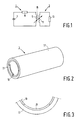
- Fig. 2 is a perspective view of the phantom 3. It is formed by a support 17 in the form of a hollow cylinder of a electrically insulating material, for example PVC, the inner surface of which is covered by a layer of an electric resistive material 19 which, evidently, is also shaped as a hollow cylinder, thus constituting a member having mainly the same shape as the RF coil.
- This layer can be provided, for example, by vapour deposition or silk screening.
- a very simple and effective method for applying a layer 19, however, is to cover the inner surface with a layer of lacquer which contains material of a predetermined specific electric resistance and which forms a layer of solid resistive material after drying. Lacquers of this kind are commercially available. An example in this respect is Electrodag 5513 marketed by Acheson.
- the electric square resistance measured on the cylinder surface depends not only on the composition of the layer 19 but also on the dimensions of the support and the thickness of the layer.
- An easy method of achieving exactly the desired resistance is to apply a layer 19 which is slightly too thick, and to remove a part of the layer at a later stage. This part is denoted by the reference 21 in Fig. 2. Removal can be effected, for example by scratching off the lacquer locally or by dissolving it by means of a suitable solvent.
- Fig. 3 is a partial axial view, at an increased scale, of the left-hand end of the phantom shown in Fig. 2. This Figure clearly shows the layer 19 with the removed part 21.
- FIG. 4 shows such an embodiment.
- the additional element 23 thereof consists of a flexible strip made of a solid material having a predetermined specific resistance. This strip may consist entirely of resistive material, but is preferably formed as a layer of a resistive material provided on a flexible, strip-shaped substrate of an electrically insulating material. This construction is, therefore, analogous to the construction of the phantom 3 described with reference to Fig. 2.
- the additional element 23 may have the same square resistance as the layer 19.
- the additional element 23 is intended to be mounted on the surface of the resistive layer 19.
- the eddy currents generated in the relevant part of the layer 19 are then increased by a given amount (i.e . the loop quality Q of the phantom is decreased), so that the loading of the RF coil increases.
- Q is adjusted to the desired value as follows. First, the Q of the cylinder is measured without additional elements. This Q is always too high. Subsequently, a strip which brings the Q to approximately the desired value is chosen from a stock of strips having different square resistances. Generally speaking, the Q will then be slightly too low. By cutting the strip to the correct width or length, an additional element can be formed whereby the desired value of Q is obtained exactly. To this end, for example an edge strip 27 is cut off.
- the additional element 23 is provided on the layer 19 so that it extends over a part of the cylinder circumference, analogous to the part 21 shown in the Figs. 2 and 3.
- the length of the short-circuit element is preferably so that the additional element extends over the entire circumference of the cylinder, so that the loading of the RF coil is uniformly distributed over the circumference.
- the additional element 23 is then shaped as a closed ring having a circumference which corresponds substantially to that of the cylinder and a height (dimension in the axial direction) which is smaller than that of the cylinder. This is shown in an end view in Fig. 5, which is analogous to that of Fig. 3.
- the support is preferably provided with fixing means, for example in the form of fingers 25 which extend in the axial direction, and underneath the free ends of which the additional element 23 can be slid.
- the resistance of the phantom 3 can be very simply adjusted to a desired value in the manners described above, no severe requirements are imposed as regards the accuracy of deposition of the layer 19.
- the phantom can also be manufactured in a very simple and inexpensive manner.
- the shape and the dimensions of the body can be adapted to any requirement.
- any other cylindrical shape or, for example the shape of a flat or curved plate can be chosen, depending on the shape of the RF coil for which the phantom is intended.
Description
Claims (4)
- A phantom for simulating the electric load constituted by an object to be examined for an RF coil (1) of a magnetic resonance apparatus, comprising a loop (3) which can be conductively coupled to the RF coil (1) and in which a predetermined electric resistance is included, characterized in that the loop (3) includes a member (19) whose shape corresponds substantially to the shape of the RF coil (1) and which is made of a solid material, the specific electric resistance and the thickness of the material being chosen so that the square resistance measured on the surface of the member is between predetermined limits, at least one strip-shaped additional element (23) made of a solid material having a predetermined specific resistance being arranged on the surface of the member in order to achieve a local decrease of the effective square resistance.
- A phantom as claimed in Claim 1, characterized in that the member (19) is formed as a layer of an electric resistive material provided on an electrically insulating support (17) having a suitably shaped surface.
- A phantom as claimed in Claim 1 or 2, characterized in that the member (19) is shaped as a hollow cylinder, the additional elements (23) being shaped as a ring having a circumference which corresponds substantially to that of the cylinder and a height which is less than that of the cylinder.
- A phantom as claimed in Claim 3, characterized in that each additional element (23) is formed as a layer of an electric resistive material provided on a strip-shaped, flexible support of an electrically insulating material.
Priority Applications (1)
| Application Number | Priority Date | Filing Date | Title |
|---|---|---|---|
| EP19930201724 EP0579300B1 (en) | 1992-06-22 | 1993-06-16 | Phantom for simulating the electric loading in a magnetic resonance apparatus |
Applications Claiming Priority (3)
| Application Number | Priority Date | Filing Date | Title |
|---|---|---|---|
| EP92201816 | 1992-06-22 | ||
| EP92201816 | 1992-06-22 | ||
| EP19930201724 EP0579300B1 (en) | 1992-06-22 | 1993-06-16 | Phantom for simulating the electric loading in a magnetic resonance apparatus |
Publications (3)
| Publication Number | Publication Date |
|---|---|
| EP0579300A2 EP0579300A2 (en) | 1994-01-19 |
| EP0579300A3 EP0579300A3 (en) | 1994-03-02 |
| EP0579300B1 true EP0579300B1 (en) | 1998-01-21 |
Family
ID=26131489
Family Applications (1)
| Application Number | Title | Priority Date | Filing Date |
|---|---|---|---|
| EP19930201724 Expired - Lifetime EP0579300B1 (en) | 1992-06-22 | 1993-06-16 | Phantom for simulating the electric loading in a magnetic resonance apparatus |
Country Status (1)
| Country | Link |
|---|---|
| EP (1) | EP0579300B1 (en) |
Families Citing this family (2)
| Publication number | Priority date | Publication date | Assignee | Title |
|---|---|---|---|---|
| WO2009153705A1 (en) * | 2008-06-20 | 2009-12-23 | Koninklijke Philips Electronics N.V. | Electronic load simulator device for testing rf coils |
| CN101615214B (en) * | 2009-07-23 | 2012-05-16 | 清华大学 | Method for conducting performance analysis on magnetic resonance imaging RF coil |
Family Cites Families (2)
| Publication number | Priority date | Publication date | Assignee | Title |
|---|---|---|---|---|
| US4719406A (en) * | 1986-02-07 | 1988-01-12 | General Electric Company | Phantom for performance evaluation of a nuclear magnetic resonance scanner |
| US4791372A (en) * | 1987-08-17 | 1988-12-13 | Resonex, Inc. | Conformable head or body coil assembly for magnetic imaging apparatus |
-
1993
- 1993-06-16 EP EP19930201724 patent/EP0579300B1/en not_active Expired - Lifetime
Also Published As
| Publication number | Publication date |
|---|---|
| EP0579300A2 (en) | 1994-01-19 |
| EP0579300A3 (en) | 1994-03-02 |
Similar Documents
| Publication | Publication Date | Title |
|---|---|---|
| US4691164A (en) | Nuclear magnetic resonance transmitter and receiver system | |
| EP0531164A1 (en) | Portable radio communication apparatus | |
| CA2595490A1 (en) | Precision rogowski coil and method for manufacturing same | |
| CA2061743A1 (en) | End loaded helix antenna | |
| US5381094A (en) | Phantom for simulating the electric loading in a magnetic resonance apparatus | |
| CA2036692C (en) | Coaxial resonator with distributed tuning capacity | |
| EP0579300B1 (en) | Phantom for simulating the electric loading in a magnetic resonance apparatus | |
| US4641115A (en) | Radio frequency chokes having two windings and means for dampening parasitic resonances | |
| GB2360093A (en) | NMR system with magnetic flux guide | |
| US3982814A (en) | Dampened choke coil | |
| EP0529905A1 (en) | High energy dissipation harmonic filter reactor | |
| US2918640A (en) | Transformer construction | |
| US2981950A (en) | Electrostatically-shielded loop antenna | |
| US4743868A (en) | High frequency filter for electric instruments | |
| GB2360137A (en) | Guides for RF magnetic flux | |
| US4092646A (en) | Flexible antenna with capacative plate coupling | |
| EP0314107A1 (en) | Power Transformer for HI-FI Equipment | |
| US2601338A (en) | Varialbe parallel resonant circuit | |
| US20080311868A1 (en) | Air coil RF transponder and method of making same | |
| US5101182A (en) | Drop-in magnetically tunable microstrip bandpass filter | |
| GB2079066A (en) | Trimmable electrical inductors | |
| US5542424A (en) | Resonator for magnetic resonance imaging | |
| US2894221A (en) | Artificial transmission lines | |
| US6636039B1 (en) | Radio-frequency antenna for a magnetic resonance apparatus | |
| JPS62123342A (en) | Loop gap resonator of electron spin resonance apparatus |
Legal Events
| Date | Code | Title | Description |
|---|---|---|---|
| PUAI | Public reference made under article 153(3) epc to a published international application that has entered the european phase |
Free format text: ORIGINAL CODE: 0009012 |
|
| PUAL | Search report despatched |
Free format text: ORIGINAL CODE: 0009013 |
|
| AK | Designated contracting states |
Kind code of ref document: A2 Designated state(s): DE FR GB NL |
|
| AK | Designated contracting states |
Kind code of ref document: A3 Designated state(s): DE FR GB NL |
|
| RAP1 | Party data changed (applicant data changed or rights of an application transferred) |
Owner name: N.V. PHILIPS' GLOEILAMPENFABRIEKEN |
|
| 17P | Request for examination filed |
Effective date: 19940825 |
|
| 17Q | First examination report despatched |
Effective date: 19960912 |
|
| GRAG | Despatch of communication of intention to grant |
Free format text: ORIGINAL CODE: EPIDOS AGRA |
|
| GRAG | Despatch of communication of intention to grant |
Free format text: ORIGINAL CODE: EPIDOS AGRA |
|
| GRAH | Despatch of communication of intention to grant a patent |
Free format text: ORIGINAL CODE: EPIDOS IGRA |
|
| GRAH | Despatch of communication of intention to grant a patent |
Free format text: ORIGINAL CODE: EPIDOS IGRA |
|
| GRAA | (expected) grant |
Free format text: ORIGINAL CODE: 0009210 |
|
| AK | Designated contracting states |
Kind code of ref document: B1 Designated state(s): DE FR GB NL |
|
| PG25 | Lapsed in a contracting state [announced via postgrant information from national office to epo] |
Ref country code: NL Free format text: LAPSE BECAUSE OF FAILURE TO SUBMIT A TRANSLATION OF THE DESCRIPTION OR TO PAY THE FEE WITHIN THE PRESCRIBED TIME-LIMIT Effective date: 19980121 |
|
| REF | Corresponds to: |
Ref document number: 69316467 Country of ref document: DE Date of ref document: 19980226 |
|
| ET | Fr: translation filed | ||
| NLV1 | Nl: lapsed or annulled due to failure to fulfill the requirements of art. 29p and 29m of the patents act | ||
| RAP4 | Party data changed (patent owner data changed or rights of a patent transferred) |
Owner name: KONINKLIJKE PHILIPS ELECTRONICS N.V. |
|
| REG | Reference to a national code |
Ref country code: FR Ref legal event code: CD |
|
| PLBE | No opposition filed within time limit |
Free format text: ORIGINAL CODE: 0009261 |
|
| STAA | Information on the status of an ep patent application or granted ep patent |
Free format text: STATUS: NO OPPOSITION FILED WITHIN TIME LIMIT |
|
| 26N | No opposition filed | ||
| PGFP | Annual fee paid to national office [announced via postgrant information from national office to epo] |
Ref country code: GB Payment date: 19990621 Year of fee payment: 7 |
|
| PGFP | Annual fee paid to national office [announced via postgrant information from national office to epo] |
Ref country code: FR Payment date: 19990628 Year of fee payment: 7 |
|
| PGFP | Annual fee paid to national office [announced via postgrant information from national office to epo] |
Ref country code: DE Payment date: 19990722 Year of fee payment: 7 |
|
| PG25 | Lapsed in a contracting state [announced via postgrant information from national office to epo] |
Ref country code: GB Free format text: LAPSE BECAUSE OF NON-PAYMENT OF DUE FEES Effective date: 20000616 |
|
| GBPC | Gb: european patent ceased through non-payment of renewal fee |
Effective date: 20000616 |
|
| PG25 | Lapsed in a contracting state [announced via postgrant information from national office to epo] |
Ref country code: FR Free format text: LAPSE BECAUSE OF NON-PAYMENT OF DUE FEES Effective date: 20010228 |
|
| REG | Reference to a national code |
Ref country code: FR Ref legal event code: ST |
|
| PG25 | Lapsed in a contracting state [announced via postgrant information from national office to epo] |
Ref country code: DE Free format text: LAPSE BECAUSE OF NON-PAYMENT OF DUE FEES Effective date: 20010403 |