EP0579288B1 - Image forming apparatus with a priority interrupt mode - Google Patents
Image forming apparatus with a priority interrupt mode Download PDFInfo
- Publication number
- EP0579288B1 EP0579288B1 EP93115979A EP93115979A EP0579288B1 EP 0579288 B1 EP0579288 B1 EP 0579288B1 EP 93115979 A EP93115979 A EP 93115979A EP 93115979 A EP93115979 A EP 93115979A EP 0579288 B1 EP0579288 B1 EP 0579288B1
- Authority
- EP
- European Patent Office
- Prior art keywords
- job
- higher priority
- image
- buffer
- interrupt
- Prior art date
- Legal status (The legal status is an assumption and is not a legal conclusion. Google has not performed a legal analysis and makes no representation as to the accuracy of the status listed.)
- Expired - Lifetime
Links
Images


Classifications
-
- G—PHYSICS
- G03—PHOTOGRAPHY; CINEMATOGRAPHY; ANALOGOUS TECHNIQUES USING WAVES OTHER THAN OPTICAL WAVES; ELECTROGRAPHY; HOLOGRAPHY
- G03G—ELECTROGRAPHY; ELECTROPHOTOGRAPHY; MAGNETOGRAPHY
- G03G15/00—Apparatus for electrographic processes using a charge pattern
- G03G15/50—Machine control of apparatus for electrographic processes using a charge pattern, e.g. regulating differents parts of the machine, multimode copiers, microprocessor control
- G03G15/5012—Priority interrupt; Job recovery, e.g. after jamming or malfunction
-
- G—PHYSICS
- G03—PHOTOGRAPHY; CINEMATOGRAPHY; ANALOGOUS TECHNIQUES USING WAVES OTHER THAN OPTICAL WAVES; ELECTROGRAPHY; HOLOGRAPHY
- G03G—ELECTROGRAPHY; ELECTROPHOTOGRAPHY; MAGNETOGRAPHY
- G03G15/00—Apparatus for electrographic processes using a charge pattern
- G03G15/36—Editing, i.e. producing a composite image by copying one or more original images or parts thereof
-
- H—ELECTRICITY
- H04—ELECTRIC COMMUNICATION TECHNIQUE
- H04N—PICTORIAL COMMUNICATION, e.g. TELEVISION
- H04N1/00—Scanning, transmission or reproduction of documents or the like, e.g. facsimile transmission; Details thereof
- H04N1/00912—Arrangements for controlling a still picture apparatus or components thereof not otherwise provided for
- H04N1/00915—Assigning priority to, or interrupting, a particular operation
- H04N1/0092—Assigning priority according to size job or task, e.g. small jobs first
-
- H—ELECTRICITY
- H04—ELECTRIC COMMUNICATION TECHNIQUE
- H04N—PICTORIAL COMMUNICATION, e.g. TELEVISION
- H04N1/00—Scanning, transmission or reproduction of documents or the like, e.g. facsimile transmission; Details thereof
- H04N1/32—Circuits or arrangements for control or supervision between transmitter and receiver or between image input and image output device, e.g. between a still-image camera and its memory or between a still-image camera and a printer device
- H04N1/32358—Circuits or arrangements for control or supervision between transmitter and receiver or between image input and image output device, e.g. between a still-image camera and its memory or between a still-image camera and a printer device using picture signal storage, e.g. at transmitter
-
- H—ELECTRICITY
- H04—ELECTRIC COMMUNICATION TECHNIQUE
- H04N—PICTORIAL COMMUNICATION, e.g. TELEVISION
- H04N1/00—Scanning, transmission or reproduction of documents or the like, e.g. facsimile transmission; Details thereof
- H04N1/32—Circuits or arrangements for control or supervision between transmitter and receiver or between image input and image output device, e.g. between a still-image camera and its memory or between a still-image camera and a printer device
- H04N1/32561—Circuits or arrangements for control or supervision between transmitter and receiver or between image input and image output device, e.g. between a still-image camera and its memory or between a still-image camera and a printer device using a programmed control device, e.g. a microprocessor
-
- H—ELECTRICITY
- H04—ELECTRIC COMMUNICATION TECHNIQUE
- H04N—PICTORIAL COMMUNICATION, e.g. TELEVISION
- H04N2201/00—Indexing scheme relating to scanning, transmission or reproduction of documents or the like, and to details thereof
- H04N2201/0077—Types of the still picture apparatus
- H04N2201/0081—Image reader
-
- H—ELECTRICITY
- H04—ELECTRIC COMMUNICATION TECHNIQUE
- H04N—PICTORIAL COMMUNICATION, e.g. TELEVISION
- H04N2201/00—Indexing scheme relating to scanning, transmission or reproduction of documents or the like, and to details thereof
- H04N2201/0077—Types of the still picture apparatus
- H04N2201/0082—Image hardcopy reproducer
-
- H—ELECTRICITY
- H04—ELECTRIC COMMUNICATION TECHNIQUE
- H04N—PICTORIAL COMMUNICATION, e.g. TELEVISION
- H04N2201/00—Indexing scheme relating to scanning, transmission or reproduction of documents or the like, and to details thereof
- H04N2201/32—Circuits or arrangements for control or supervision between transmitter and receiver or between image input and image output device, e.g. between a still-image camera and its memory or between a still-image camera and a printer device
- H04N2201/3285—Circuits or arrangements for control or supervision between transmitter and receiver or between image input and image output device, e.g. between a still-image camera and its memory or between a still-image camera and a printer device using picture signal storage, e.g. at transmitter
- H04N2201/3295—Deletion of stored data; Preventing such deletion
-
- H—ELECTRICITY
- H04—ELECTRIC COMMUNICATION TECHNIQUE
- H04N—PICTORIAL COMMUNICATION, e.g. TELEVISION
- H04N2201/00—Indexing scheme relating to scanning, transmission or reproduction of documents or the like, and to details thereof
- H04N2201/32—Circuits or arrangements for control or supervision between transmitter and receiver or between image input and image output device, e.g. between a still-image camera and its memory or between a still-image camera and a printer device
- H04N2201/3285—Circuits or arrangements for control or supervision between transmitter and receiver or between image input and image output device, e.g. between a still-image camera and its memory or between a still-image camera and a printer device using picture signal storage, e.g. at transmitter
- H04N2201/3298—Checking or indicating the storage space
Definitions
- This invention relates generally to copying apparatus having an editing mode for identifying areas of original documents of a first production run for special treatment, and more specifically to interrupting the editing mode to complete a higher priority job and to thereafter reinstate the status of the apparatus to complete the remainder of the editing mode of the first production run which was interrupted.
- Copiers having image editing modes are well known.
- electrophotographic reproduction apparatus in which an original document to be copied is placed face up on an exposure platen, whereat a wand is used by an operator to identify locations on the original document which define an area for special treatment such as screening, erase, annotation, spot coloration (also called “accent coloring"), relocation in the page format, etc.
- the area of the original document to which that treatment is to be applied is defined by identifying two or more corners thereof. Should a job be interrupted after the first corner is identified but before the last, the operator might forget how far he or she was into the edit.
- the present invention specifies various stages during the editing process at which an interrupt may and may not occur.
- Copiers are known that include a buffer memory for electronically storing scanned image data and printing instructions for a plurality of pages of a job. Once stored, the pages can be printed as often as desired to produce a plurality of collated sets. If such a copier had a priority interrupt mode operable during scanning, the higher priority job would be loaded into buffer along with the data for the interrupted production run.
- the higher priority job is limited to a single image frame such that duplex copies and multi-color copies which require more than one image frame to produce are excluded. If there is insufficient space in the buffer for storing the data for the higher priority job, the interrupt mode is disabled. once the higher priority job is produced, its data is erased from buffer.
- an image forming apparatus e.g. document copier as defined in claim 1.
- a document copier includes a job image buffer capable of holding a predetermined amount of data.
- Production means are operable (1) for converting images on original documents to electronic bit stream data in image frame format for input to the job image buffer and (2) for reproducing pages from image frames stored in the job image buffer.
- the production means operation can be interrupted so that a job of higher priority can be processed, wherein the interrupt means is disabled when there is insufficient space in the job image buffer for storing the data for the higher priority job.
- the higher priority job may be limited to a single image frame such that duplex copies and multi-color copies which require more than one image frame to produce may be excluded.
- the data for the higher priority job is erased from the job image buffer after only one copy is produced, whereby multiple copies of said higher priority job cannot be produced.
- copiers are well known, the present description will be directed in particular to elements forming part of or cooperating more directly with the present invention. Apparatus not specifically shown or described herein are selectable from those known in the prior art.
- a copier 1 is made up of a marking engine 2 and a scanner 3.
- the scanner includes a document handler 4 and an optical system enclosed in an optics housing 5. Details of the scanner are disclosed in US-A-4,884,097, published on November 28, 1989, filed in the names of Giannetti et al. on December 24, 1987. The disclosure of that application is incorporated herein by reference.
- a document editor such as a digitizer tablet is incorporated in the scanner, and will be further explained below.
- scanner 3 consists of automatic document handler 4 for stream feeding hardcopy input originals to be automatically read by a solid-state device to such as a linear array of charge-coupled devices.
- the solid-state device scans the input originals, converting their images to electronic bit stream data in page format for input to marking engine 2.
- This data may be manipulated by image processing electronics 7 having an algorithm to enhance the data to optimize the marking engine electrophotographic process.
- Scanner 3 also includes a control logic package 8 having an operator control panel for the operator to input functions and for messages received from the copier. setup information is input to the scanner and information for finishing and processing of jobs will be sent to marking engine 2.
- the package consists of control software, interface software, and logic hardware.
- Marking engine 2 is the output device that will receive and store bit stream data in its job image buffer 9 and appropriately process that data for copies.
- the job image buffer stores the bit stream data for each of the pages being copied and delivers these data to a writing head 10 as necessary for sequential copying.
- the marking engine incorporates the paper handling, photoconductor and process hardware, and writing head 10.
- FIG. 3 schematically illustrates the electrophotographic apparatus of copier 1, including an image transfer member such as photoconductive belt 12.
- Belt 12 is moved in a clockwise direction, as represented by arrow 14.
- a primary charging station 16 applies an electrostatic charge to belt 12.
- projected light from an exposure station 20 dissipates the electrostatic charge on the photoconductive belt to form a latent electrostatic image corresponding to the image of an original to be copied or printed.
- Exposure station 20 preferable consists of an array of light emitting diodes such as writing head 10 for exposing the photoconductive belt.
- the latent electrostatic image on belt 12 is developed with toner at a developer station 22.
- the developer station is illustrated as having four separate substations 24, 25, 26 and 27 for processing color images; the substations containing magenta, cyan, yellow, and black toner, respectively. Although four-color capability is illustrated, the present invention is applicable also to monochromatic images.
- an image receiver sheet 30 is fed from a supply 32. After transfer of the toner image to the receiver sheet, the receiver sheet is passed through a pair of heated fuser rollers 34 and 36. Mechanical and electrical cleaning of belt 12 is effected at a cleaning station 38.
- FIG. 4 illustrates an operator control panel 40 which is part of control logic package 8 scanner 3.
- Panel 40 includes a display 42 upon which messages are shown to indicate to the operator what mode the copier is operating in, what action should be taken next, where malfunctions may be located in the copier, etc.
- Panel 40 includes soft keys below display 42, a key pad 44, a digital display 45, a "start” button 46, a "reset/stop” button 48, and a "proof” button 50. Job interrupt may be initiated from one of the soft keys below display 42.
- Figure 5 shows a digitizer 52 having an exposure platen 54 which in this example may serve as the support for digitizing an original document 56.
- a corner of the original document is registered in one corner of the platen to establish a coordinate reference system for inputting information into temporary memory regarding the location of the areas to be operated upon.
- Digitizers are well known in the art, and the reader is referred to various U.S. patents, including 4,562,485, 4,617,596, 4,674,861, and 4,740,818 as examples of copiers with image editing features.
- Figure 5 shows the upper right corner of the original document sheet registered with a corner reference of the platen.
- special treatment i.e., screening, erase, annotation, spot coloration (also called “accent coloring"), relocation in the page format, etc.
- the original document includes an area P 1 which is to be enlarged and relocated in the region P 2 of the copy.
- the operator digitizes the "begin" command on a command strip 57 to call up a stored program which requests, through display 42 that the operator indicate by means of a conventional wand 58 the position of areas P 1 and P 2 relative to the reference corner.
- the wand may be used to touch the sheet at the four corner points of each area.
- the points are touched in an order such that a straight line joins adjacent points as in the order a, b, c, and d to define a rectangle.
- the rectangles can be defined by touching only two diagonally opposed corners.
- the computer control for the digitizing tablet may also be programmed to accept inputs of area data to define other geometrical shapes such as circles.
- Transducers located beneath the sheet produce signals relating the position of the points touched relative to the reference corner of the sheet.
- the tablet may be of the known sonic type wherein a spark formed by a wand creates sound waves in the air which are sensed by microphones placed along the sides of the exposure platen or wherein a sensor is placed in the wand and sources at known points on the sides of the platen emit sonic signals (see, for example, U.S. Patents Nos. 4,012,588 in the name of Davis et al. and 4,124,838 in the name of Kiss).
- a digitizer controller 60 knowing the times of emitting of the signals and their receipt, can through triangulation principles calculate the location of a point on the platen relative to a known point such as the reference corner shown. Controller 60 is programmed to recognize that the area is bordered by the straight lines joining adjacent points a, b, c, and d and the coordinates for areas P 1 and P 2 can be thus calculated and stored in temporary memory. This information is outputted on display 42 showing the areas.
- the document is flipped over on the exposure platen with the document sheet appropriately registered such as with the "staple" corner in another reference corner of the platen.
- Suitable logic or computing means is provided to translate the area defining points determined during the editing mode to points on an image frame of the photoconductor belt's surface. Job interrupt may be initiated from command strip 57 as well as the soft keys below display 42.
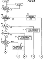
- FIG. 6A there is shown a flow chart of the interrupt mode operation of the apparatus of Figures 1-5.
- the program determines first if this job is presently in the interrupt mode; decisional block 64. If so, the logic assumes that the operator is indicating that the interrupt is completed, and the copier is returned to the interrupted job, logic block 66.
- interrupt button 50 When interrupt button 50 is pressed, additional memory space is allocated in buffer 9 for a higher priority job page, and the control panel is set up with the proper defaults for an interrupt job. Preferable, the control panel will be set to simplex mode and monocolor to conserve memory space since duplex and multi-color copies require more than one image frame on photoconductor belt 12. The operator will be advised that the machine is in the interrupt mode, and that the platen rather than the document handler is to be used. Of course, if the entire buffer were full, the interrupt mode would be disallowed.
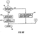
- decisional block 68 if the marking engine were not in the production mode at the time of interrupt, the logic would exit the block to a decisional block 72; whereat it would be determined if the scanner were in operation. If so, functions for handling a job interrupt during scanning are selected; block 74. Such functions might include the shutdown of the document handler; scanning the original documents that are already in the paper path but not feeding any more.
- the logic determines at block 78 ( Figure 6B) if the apparatus is stopped because of a malfunction such as a paper jam, out of supplies, etc. If not, there is apparently no job in the machine; so there is nothing to interrupt. Therefore, the mode is not allowed, and the operator is so informed; steps 80 and 82, respectively.
- Logic block 86 represents the step of exiting from the interrupt mode.
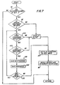
- the logic is queried whether the marking engine would allow an interrupt; decisional block 90.
- An example of when interrupt would not be allowed is if the job image buffer were full. In that case, appropriate instructions would be displayed.
- step 94 If the interrupt mode is allowed (step 90) and no special features have yet been identified (step 92), a flag is set at step 94 so that the edit mode will be re-entered after the interrupt job is completed. Now the copier enters its job interrupt mode, and the selections are set as set forth below; step 96.
- step 92 If the decision at step 92 had been "yes” rather than "no," and all the corners of the area of the original document for that special feature had not yet been identified, the logic exits either step 100 or 102 and enters step 94 discussed above. If the area has been completely defined, the special feature is saved so as to be available when the interrupt job is complete (step 103) and the coordinate data is also saved, step 104. The process is repeated until all identified special features and areas have been saved, step 106. After the area information is saved, those features associated with the entire job and to the current page being editing are saved in backup memory.
- the setup parameters selected for interrupt jobs might preferably include one copy requested, monocolor, normal exposure, 100% reduction, main paper supply, simplex to simplex copying, no covers, no finishing, etc.
- all special features will be turned off, including image editing for the interrupt job. It might be desirable to allow the operator to change the paper supply selection, exposure, margin shift, color selection for an entire page, and reduction/enlargement ratios for the interrupt job.
Description
- This invention relates generally to copying apparatus having an editing mode for identifying areas of original documents of a first production run for special treatment, and more specifically to interrupting the editing mode to complete a higher priority job and to thereafter reinstate the status of the apparatus to complete the remainder of the editing mode of the first production run which was interrupted.
- Copiers having image editing modes are well known. In U.S. Patent No. 4,740,818, electrophotographic reproduction apparatus is described in which an original document to be copied is placed face up on an exposure platen, whereat a wand is used by an operator to identify locations on the original document which define an area for special treatment such as screening, erase, annotation, spot coloration (also called "accent coloring"), relocation in the page format, etc.
- Often, it is necessary to interrupt a production run in mid-stream so that a job of higher priority can be processed. If such interruption occurs during the printing mode, there is generally no problem. However, interruption of the editing mode could well result in operator confusion when the interrupted edit mode is reinstated. Once a special treatment is selected, the area of the original document to which that treatment is to be applied is defined by identifying two or more corners thereof. Should a job be interrupted after the first corner is identified but before the last, the operator might forget how far he or she was into the edit.
- Accordingly, the present invention specifies various stages during the editing process at which an interrupt may and may not occur.
- Copiers are known that include a buffer memory for electronically storing scanned image data and printing instructions for a plurality of pages of a job. Once stored, the pages can be printed as often as desired to produce a plurality of collated sets. If such a copier had a priority interrupt mode operable during scanning, the higher priority job would be loaded into buffer along with the data for the interrupted production run. By the present invention, accommodation is made for the higher priority job data in the such copiers. Preferably, the higher priority job is limited to a single image frame such that duplex copies and multi-color copies which require more than one image frame to produce are excluded. If there is insufficient space in the buffer for storing the data for the higher priority job, the interrupt mode is disabled. once the higher priority job is produced, its data is erased from buffer.
- US-A-4,099,860 discloses a copier with an interruption mode which allows to process a job of higher priority. Selected features of the interrupted job, such as the number of remaining copies, are stored in a memory and recalled to continue the interrupted job, when the job of higher priority is finished.
- According to the present invention, there is provided an image forming apparatus, e.g. document copier as defined in claim 1.
- Essentially, a document copier includes a job image buffer capable of holding a predetermined amount of data. Production means are operable (1) for converting images on original documents to electronic bit stream data in image frame format for input to the job image buffer and (2) for reproducing pages from image frames stored in the job image buffer. The production means operation can be interrupted so that a job of higher priority can be processed, wherein the interrupt means is disabled when there is insufficient space in the job image buffer for storing the data for the higher priority job.
- According to another feature of the present invention, the higher priority job may be limited to a single image frame such that duplex copies and multi-color copies which require more than one image frame to produce may be excluded.
- According to still another feature of the present invention, the data for the higher priority job is erased from the job image buffer after only one copy is produced, whereby multiple copies of said higher priority job cannot be produced.
- The invention, and its objects and advantages, will become more apparent in the detailed description of the preferred embodiments presented below.
- In the detailed description of the preferred embodiments of the invention presented below, reference is made to the accompanying drawings, in which:
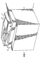
- Figure 1 is a perspective view of one embodiment of an electrophotographic copier for practice of the present invention;
- Figure 2 is a schematic block diagram of the copier of Figure 1;
- Figure 3 is a schematic front elevational view of the copier of Figures 1 and 2 showing the general arrangement of electrophotographic reproduction apparatus in accordance with one embodiment of the invention;
- Figure 4 is a view of an operator control panel of the copier of Figures 1-3;
- Figure 5 is a schematic view of a digitizer tablet which is part of the copier of Figures 1-4; and
- Figures 6A, 6B, and 7 are logic flow charts of the operation of the copier of Figures 1-5.
- Because copiers are well known, the present description will be directed in particular to elements forming part of or cooperating more directly with the present invention. Apparatus not specifically shown or described herein are selectable from those known in the prior art.
- With reference now to Figure 1, a copier 1 is made up of a marking engine 2 and a
scanner 3. The scanner includes a document handler 4 and an optical system enclosed in an optics housing 5. Details of the scanner are disclosed in US-A-4,884,097, published on November 28, 1989, filed in the names of Giannetti et al. on December 24, 1987. The disclosure of that application is incorporated herein by reference. A document editor such as a digitizer tablet is incorporated in the scanner, and will be further explained below. - Referring to Figure 2,
scanner 3 consists of automatic document handler 4 for stream feeding hardcopy input originals to be automatically read by a solid-state device to such as a linear array of charge-coupled devices. The solid-state device scans the input originals, converting their images to electronic bit stream data in page format for input to marking engine 2. This data may be manipulated by image processing electronics 7 having an algorithm to enhance the data to optimize the marking engine electrophotographic process. -
Scanner 3 also includes a control logic package 8 having an operator control panel for the operator to input functions and for messages received from the copier. setup information is input to the scanner and information for finishing and processing of jobs will be sent to marking engine 2. The package consists of control software, interface software, and logic hardware. - Marking engine 2 is the output device that will receive and store bit stream data in its
job image buffer 9 and appropriately process that data for copies. The job image buffer stores the bit stream data for each of the pages being copied and delivers these data to awriting head 10 as necessary for sequential copying. The marking engine incorporates the paper handling, photoconductor and process hardware, and writinghead 10. - Figure 3 schematically illustrates the electrophotographic apparatus of copier 1, including an image transfer member such as
photoconductive belt 12.Belt 12 is moved in a clockwise direction, as represented by arrow 14. - A
primary charging station 16 applies an electrostatic charge to belt 12. At anexposure station 18, projected light from anexposure station 20 dissipates the electrostatic charge on the photoconductive belt to form a latent electrostatic image corresponding to the image of an original to be copied or printed.Exposure station 20 preferable consists of an array of light emitting diodes such as writinghead 10 for exposing the photoconductive belt. - The latent electrostatic image on
belt 12 is developed with toner at adeveloper station 22. The developer station is illustrated as having fourseparate substations - As the toner image on
belt 12 approaches atransfer station 28, animage receiver sheet 30 is fed from asupply 32. After transfer of the toner image to the receiver sheet, the receiver sheet is passed through a pair of heatedfuser rollers belt 12 is effected at acleaning station 38. - Figure 4 illustrates an
operator control panel 40 which is part of control logic package 8scanner 3.Panel 40 includes adisplay 42 upon which messages are shown to indicate to the operator what mode the copier is operating in, what action should be taken next, where malfunctions may be located in the copier, etc.Panel 40 includes soft keys belowdisplay 42, a key pad 44, adigital display 45, a "start"button 46, a "reset/stop"button 48, and a "proof"button 50. Job interrupt may be initiated from one of the soft keys belowdisplay 42. - Figure 5 shows a
digitizer 52 having anexposure platen 54 which in this example may serve as the support for digitizing anoriginal document 56. A corner of the original document is registered in one corner of the platen to establish a coordinate reference system for inputting information into temporary memory regarding the location of the areas to be operated upon. Digitizers are well known in the art, and the reader is referred to various U.S. patents, including 4,562,485, 4,617,596, 4,674,861, and 4,740,818 as examples of copiers with image editing features. - Through
display 42, requests are made that the operator placeoriginal document sheet 56 face-up uponexposure platen 54. Figure 5 shows the upper right corner of the original document sheet registered with a corner reference of the platen. However, one might prefer to adapt the machine so as to register the "staple" corner of the sheet with the appropriate corner reference of the platen. The operator is then requested to select which special treatment is desired; i.e., screening, erase, annotation, spot coloration (also called "accent coloring"), relocation in the page format, etc. - As an example to explain the operation of the editing mode, it is assumed that the original document includes an area P1 which is to be enlarged and relocated in the region P2 of the copy. Once the original document is registered such as with the "staple" corner in a reference corner of the exposure platen, the operator digitizes the "begin" command on a
command strip 57 to call up a stored program which requests, throughdisplay 42 that the operator indicate by means of aconventional wand 58 the position of areas P1 and P2 relative to the reference corner. The wand may be used to touch the sheet at the four corner points of each area. Preferably the points are touched in an order such that a straight line joins adjacent points as in the order a, b, c, and d to define a rectangle. Alternately, the rectangles can be defined by touching only two diagonally opposed corners. The computer control for the digitizing tablet may also be programmed to accept inputs of area data to define other geometrical shapes such as circles. - Transducers located beneath the sheet produce signals relating the position of the points touched relative to the reference corner of the sheet. Alternatively, the tablet may be of the known sonic type wherein a spark formed by a wand creates sound waves in the air which are sensed by microphones placed along the sides of the exposure platen or wherein a sensor is placed in the wand and sources at known points on the sides of the platen emit sonic signals (see, for example, U.S. Patents Nos. 4,012,588 in the name of Davis et al. and 4,124,838 in the name of Kiss). A digitizer controller 60 knowing the times of emitting of the signals and their receipt, can through triangulation principles calculate the location of a point on the platen relative to a known point such as the reference corner shown. Controller 60 is programmed to recognize that the area is bordered by the straight lines joining adjacent points a, b, c, and d and the coordinates for areas P1 and P2 can be thus calculated and stored in temporary memory. This information is outputted on
display 42 showing the areas. - The document is flipped over on the exposure platen with the document sheet appropriately registered such as with the "staple" corner in another reference corner of the platen. Suitable logic or computing means is provided to translate the area defining points determined during the editing mode to points on an image frame of the photoconductor belt's surface. Job interrupt may be initiated from
command strip 57 as well as the soft keys belowdisplay 42. - Referring to Figure 6A, there is shown a flow chart of the interrupt mode operation of the apparatus of Figures 1-5. When job interrupt
button 50 is pushed, as determined by adecisional block 62, the program determines first if this job is presently in the interrupt mode;decisional block 64. If so, the logic assumes that the operator is indicating that the interrupt is completed, and the copier is returned to the interrupted job, logic block 66. - If on the otherhand, the decision at
block 64 was "no" rather than "yes," the logic would progress to adecisional block 68, whereat it would be determined if the marking engine was printing a job. If so, conventional functions for handling an interrupt during printing, including saving selected features of the interrupted job, stopping the production run, and storing in memory the remaining number of copies of the interrupted job plus other desired pertinent machine status information as described in U.S. Patent No. 4,099,860, are implemented;logic block 70. Depending on how the copier is set up, the shut down can be effected either at the end of a set, or at the end of the page currently being produced. - When interrupt
button 50 is pressed, additional memory space is allocated inbuffer 9 for a higher priority job page, and the control panel is set up with the proper defaults for an interrupt job. Preferable, the control panel will be set to simplex mode and monocolor to conserve memory space since duplex and multi-color copies require more than one image frame onphotoconductor belt 12. The operator will be advised that the machine is in the interrupt mode, and that the platen rather than the document handler is to be used. Of course, if the entire buffer were full, the interrupt mode would be disallowed. - Returning to
decisional block 68, if the marking engine were not in the production mode at the time of interrupt, the logic would exit the block to adecisional block 72; whereat it would be determined if the scanner were in operation. If so, functions for handling a job interrupt during scanning are selected;block 74. Such functions might include the shutdown of the document handler; scanning the original documents that are already in the paper path but not feeding any more. - If the scanner is not running, and the interrupt command is received when the apparatus is not in the editing mode as determined at logic
decisional block 76, the logic determines at block 78 (Figure 6B) if the apparatus is stopped because of a malfunction such as a paper jam, out of supplies, etc. If not, there is apparently no job in the machine; so there is nothing to interrupt. Therefore, the mode is not allowed, and the operator is so informed;steps - If, on the otherhand, the apparatus has shut down for a malfunction, the interrupt is again disallowed, but different type messages are displayed; such as those needed to correct the malfunction,
logic step 84. Once this was done, the interrupt would be permitted.Logic block 86 represents the step of exiting from the interrupt mode. - If the decision at
block 76 had been "yes" instead of "no," the logic would exit to block 88, containing functions for handling job interrupt during an editing mode. Figure 7 is a detailed chart of a subroutine effecting those functions. - Initially, the logic is queried whether the marking engine would allow an interrupt;
decisional block 90. An example of when interrupt would not be allowed is if the job image buffer were full. In that case, appropriate instructions would be displayed. - If the interrupt mode is allowed (step 90) and no special features have yet been identified (step 92), a flag is set at
step 94 so that the edit mode will be re-entered after the interrupt job is completed. Now the copier enters its job interrupt mode, and the selections are set as set forth below;step 96. - If the decision at
step 92 had been "yes" rather than "no," and all the corners of the area of the original document for that special feature had not yet been identified, the logic exits either step 100 or 102 and entersstep 94 discussed above. If the area has been completely defined, the special feature is saved so as to be available when the interrupt job is complete (step 103) and the coordinate data is also saved,step 104. The process is repeated until all identified special features and areas have been saved,step 106. After the area information is saved, those features associated with the entire job and to the current page being editing are saved in backup memory. - Referring back to step 96 the setup parameters selected for interrupt jobs might preferably include one copy requested, monocolor, normal exposure, 100% reduction, main paper supply, simplex to simplex copying, no covers, no finishing, etc. Generally, all special features will be turned off, including image editing for the interrupt job. It might be desirable to allow the operator to change the paper supply selection, exposure, margin shift, color selection for an entire page, and reduction/enlargement ratios for the interrupt job.
- The invention has been described in detail with particular reference to preferred embodiments thereof, but it will be understood that variations and modifications can be effected within the scope of the invention.
Claims (5)
- An image forming apparatus (1) comprising:a buffer (9) for storing image data representing a job to be processed;production means (2) for producing pages from said image data stored in said buffer (9);interrupt means for interrupting said production means so that a job of higher priority can be processed; characterized bymeans for disabling said interrupt means when there is insufficient space in said buffer for storing the data for said higher priority job.
- The apparatus of claim 1, wherein said production means includes means operable for converting images on original documents to electronic bit stream data in image frame format for input to said buffer.
- The apparatus of claims 1 or 2, including means for resuming operation of said production means upon completion of the higher priority job.
- The apparatus of claims 1, 2 or 3, further characterized by means (3, 8) for setting said apparatus in a production mode for producing said higher priority job which mode is limited to producing a document using a single image frame such that production of a document that requires more than one image frame to produce is excluded.
- The apparatus (1) of any of claims 1 through 4, further characterized bymeans (2, 3) for producing said higher priority job from data stored in said job image buffer means; andmeans (3, 8, 7) for erasing the data for said higher priority job from said job image buffer means after one copy is produced whereby multiple copies of said higher priority job cannot be produced.
Priority Applications (1)
| Application Number | Priority Date | Filing Date | Title |
|---|---|---|---|
| EP95118040A EP0702274B1 (en) | 1989-06-23 | 1990-06-15 | Image forming apparatus with priority interrupt mode |
Applications Claiming Priority (3)
| Application Number | Priority Date | Filing Date | Title |
|---|---|---|---|
| US371238 | 1989-06-23 | ||
| US07/371,238 US4956667A (en) | 1989-06-23 | 1989-06-23 | Priority interrupt during editing mode |
| EP90910016A EP0433421B1 (en) | 1989-06-23 | 1990-06-15 | Priority interrupt during editing mode |
Related Parent Applications (1)
| Application Number | Title | Priority Date | Filing Date |
|---|---|---|---|
| EP90910016.6 Division | 1990-06-15 |
Related Child Applications (2)
| Application Number | Title | Priority Date | Filing Date |
|---|---|---|---|
| EP95118040.5 Division-Into | 1990-06-15 | ||
| EP95118040A Division EP0702274B1 (en) | 1989-06-23 | 1990-06-15 | Image forming apparatus with priority interrupt mode |
Publications (3)
| Publication Number | Publication Date |
|---|---|
| EP0579288A2 EP0579288A2 (en) | 1994-01-19 |
| EP0579288A3 EP0579288A3 (en) | 1994-02-23 |
| EP0579288B1 true EP0579288B1 (en) | 1996-08-21 |
Family
ID=23463109
Family Applications (3)
| Application Number | Title | Priority Date | Filing Date |
|---|---|---|---|
| EP95118040A Expired - Lifetime EP0702274B1 (en) | 1989-06-23 | 1990-06-15 | Image forming apparatus with priority interrupt mode |
| EP93115979A Expired - Lifetime EP0579288B1 (en) | 1989-06-23 | 1990-06-15 | Image forming apparatus with a priority interrupt mode |
| EP90910016A Expired - Lifetime EP0433421B1 (en) | 1989-06-23 | 1990-06-15 | Priority interrupt during editing mode |
Family Applications Before (1)
| Application Number | Title | Priority Date | Filing Date |
|---|---|---|---|
| EP95118040A Expired - Lifetime EP0702274B1 (en) | 1989-06-23 | 1990-06-15 | Image forming apparatus with priority interrupt mode |
Family Applications After (1)
| Application Number | Title | Priority Date | Filing Date |
|---|---|---|---|
| EP90910016A Expired - Lifetime EP0433421B1 (en) | 1989-06-23 | 1990-06-15 | Priority interrupt during editing mode |
Country Status (5)
| Country | Link |
|---|---|
| US (1) | US4956667A (en) |
| EP (3) | EP0702274B1 (en) |
| JP (2) | JPH04500444A (en) |
| DE (3) | DE69032231T2 (en) |
| WO (1) | WO1991000549A1 (en) |
Families Citing this family (19)
| Publication number | Priority date | Publication date | Assignee | Title |
|---|---|---|---|---|
| JPH03119369A (en) * | 1989-10-02 | 1991-05-21 | Minolta Camera Co Ltd | Multifunctional copying machine |
| US5081494A (en) * | 1990-06-15 | 1992-01-14 | Xerox Corporation | Job supplement for electronic printing machines |
| US5164842A (en) * | 1990-06-29 | 1992-11-17 | Xerox Corporation | Job/page proofing for electronic printers |
| US5206735A (en) * | 1990-06-29 | 1993-04-27 | Xerox Corporation | Job interrupt for electronic copying/printing machines |
| EP0499719B1 (en) * | 1991-02-20 | 1996-12-18 | Océ-Nederland B.V. | Digital image reproduction system |
| US5274468A (en) * | 1991-06-27 | 1993-12-28 | Ojha Purnendu S | Reproduction apparatus and method with user-definable editing and machine operation functions |
| JP3311060B2 (en) * | 1992-02-26 | 2002-08-05 | キヤノン株式会社 | Image forming system |
| US5384633A (en) * | 1993-03-24 | 1995-01-24 | Xerox Corporation | Copy waiting machine interrupt slot mode |
| US5511150A (en) * | 1993-11-29 | 1996-04-23 | Eastman Kodak Company | Copier/printer with improved productivity |
| US5535009A (en) * | 1993-12-28 | 1996-07-09 | Eastman Kodak Company | Copier/printer operating with interrupts |
| US5812907A (en) * | 1994-08-31 | 1998-09-22 | Canon Kabushiki Kaisha | Image processing apparatus which can interrupt a current job to execute another job |
| EP0762724A3 (en) * | 1995-08-31 | 1998-05-20 | Kabushiki Kaisha Toshiba | Image forming apparatus performing interruption process in electronic sorting mode |
| JPH09163067A (en) * | 1995-12-14 | 1997-06-20 | Minolta Co Ltd | Image processor |
| US5933686A (en) * | 1995-12-31 | 1999-08-03 | Minolta Co., Ltd. | Image processing unit having reserve function |
| JP3935252B2 (en) * | 1997-12-26 | 2007-06-20 | キヤノン株式会社 | Image forming apparatus and job processing method |
| DE19840382C2 (en) * | 1998-09-04 | 2001-12-06 | Agfa Gevaert Ag | Method and device for digitally exposing images to light-sensitive material |
| JP2000305421A (en) * | 1999-04-21 | 2000-11-02 | Konica Corp | Image forming device |
| US20060082816A1 (en) * | 2004-10-15 | 2006-04-20 | Lexmark International, Inc. | Printer device and related method for handling print-and-hold jobs |
| US7697861B2 (en) * | 2005-12-28 | 2010-04-13 | Ricoh Company, Limited | Printing apparatus and image forming apparatus |
Citations (1)
| Publication number | Priority date | Publication date | Assignee | Title |
|---|---|---|---|---|
| US4099860A (en) * | 1972-12-05 | 1978-07-11 | Eastman Kodak Company | Copier/duplicator priority interrupt apparatus |
Family Cites Families (7)
| Publication number | Priority date | Publication date | Assignee | Title |
|---|---|---|---|---|
| JPS549920A (en) * | 1977-06-24 | 1979-01-25 | Canon Inc | Automatic original handling device |
| EP0062121B1 (en) * | 1981-04-08 | 1986-07-16 | International Business Machines Corporation | Text processing apparatus with two-stage formatting of text |
| US4597006A (en) * | 1983-05-18 | 1986-06-24 | Vta Technologies, Inc. | Video signal control system |
| JPS6037871A (en) * | 1983-08-10 | 1985-02-27 | Toshiba Corp | Image forming device |
| JPS60130758A (en) * | 1983-12-20 | 1985-07-12 | Toshiba Corp | Image forming device |
| US4740818A (en) * | 1985-12-16 | 1988-04-26 | Eastman Kodak Company | Electrophotographic reproduction apparatus and method with selective screening |
| JPH01185675A (en) * | 1988-01-19 | 1989-07-25 | Minolta Camera Co Ltd | Image forming device |
-
1989
- 1989-06-23 US US07/371,238 patent/US4956667A/en not_active Expired - Lifetime
-
1990
- 1990-06-15 WO PCT/US1990/003412 patent/WO1991000549A1/en active IP Right Grant
- 1990-06-15 EP EP95118040A patent/EP0702274B1/en not_active Expired - Lifetime
- 1990-06-15 DE DE69032231T patent/DE69032231T2/en not_active Expired - Fee Related
- 1990-06-15 DE DE69009420T patent/DE69009420T2/en not_active Expired - Fee Related
- 1990-06-15 DE DE69028218T patent/DE69028218T2/en not_active Expired - Fee Related
- 1990-06-15 EP EP93115979A patent/EP0579288B1/en not_active Expired - Lifetime
- 1990-06-15 JP JP2509237A patent/JPH04500444A/en active Pending
- 1990-06-15 EP EP90910016A patent/EP0433421B1/en not_active Expired - Lifetime
-
1999
- 1999-11-16 JP JP11324993A patent/JP2000216937A/en active Pending
Patent Citations (1)
| Publication number | Priority date | Publication date | Assignee | Title |
|---|---|---|---|---|
| US4099860A (en) * | 1972-12-05 | 1978-07-11 | Eastman Kodak Company | Copier/duplicator priority interrupt apparatus |
Also Published As
| Publication number | Publication date |
|---|---|
| JP2000216937A (en) | 2000-08-04 |
| EP0702274A2 (en) | 1996-03-20 |
| WO1991000549A1 (en) | 1991-01-10 |
| DE69032231T2 (en) | 1998-11-12 |
| EP0702274B1 (en) | 1998-04-08 |
| US4956667A (en) | 1990-09-11 |
| DE69009420D1 (en) | 1994-07-07 |
| EP0433421A1 (en) | 1991-06-26 |
| DE69009420T2 (en) | 1995-01-05 |
| EP0702274A3 (en) | 1996-05-15 |
| EP0579288A3 (en) | 1994-02-23 |
| EP0433421B1 (en) | 1994-06-01 |
| DE69028218D1 (en) | 1996-09-26 |
| JPH04500444A (en) | 1992-01-23 |
| DE69028218T2 (en) | 1997-03-20 |
| EP0579288A2 (en) | 1994-01-19 |
| DE69032231D1 (en) | 1998-05-14 |
Similar Documents
| Publication | Publication Date | Title |
|---|---|---|
| EP0579288B1 (en) | Image forming apparatus with a priority interrupt mode | |
| JP3334025B2 (en) | Image forming device | |
| GB2284319A (en) | Copier/printer with improved productivity | |
| US4980725A (en) | Background accenuating image forming apparatus | |
| EP0725528B1 (en) | Copier apparatus and method with flexible source document entry scanning in an image overlay mode | |
| US5185662A (en) | Method and apparatus for producing copy with selective area treatment | |
| JP3389810B2 (en) | Image forming device | |
| US5794099A (en) | Copier apparatus and method with flexible source document entry scanning with display of options for selection of source | |
| US5983051A (en) | Image formation apparatus executing plurality registered jobs in order | |
| US5299021A (en) | Copier with mode for collating off a platen | |
| JP4318199B2 (en) | Image forming apparatus and copying apparatus | |
| US6654140B1 (en) | Image forming apparatus that permits easy job registration | |
| EP0418029A2 (en) | Reprographic system | |
| JP3142428B2 (en) | Image forming device | |
| JP2617022B2 (en) | Electrophotographic equipment | |
| US5243442A (en) | Copying machine equippd with an image editor | |
| JPH0619618B2 (en) | Image editing copier | |
| JP3418942B2 (en) | Copier | |
| JP3264710B2 (en) | Image forming device | |
| JPS6225770A (en) | Copying device | |
| JPS613182A (en) | Picture editing copying machine | |
| JPH01302364A (en) | Image forming device | |
| JPS626577A (en) | Picture processor | |
| JPH01271780A (en) | Image recording device equipped with information adding function | |
| JPH01235972A (en) | Recorder with information adding function |
Legal Events
| Date | Code | Title | Description |
|---|---|---|---|
| PUAI | Public reference made under article 153(3) epc to a published international application that has entered the european phase |
Free format text: ORIGINAL CODE: 0009012 |
|
| PUAL | Search report despatched |
Free format text: ORIGINAL CODE: 0009013 |
|
| 17P | Request for examination filed |
Effective date: 19931004 |
|
| AC | Divisional application: reference to earlier application |
Ref document number: 433421 Country of ref document: EP |
|
| AK | Designated contracting states |
Kind code of ref document: A2 Designated state(s): DE FR GB NL |
|
| AK | Designated contracting states |
Kind code of ref document: A3 Designated state(s): DE FR GB NL |
|
| 17Q | First examination report despatched |
Effective date: 19950327 |
|
| GRAH | Despatch of communication of intention to grant a patent |
Free format text: ORIGINAL CODE: EPIDOS IGRA |
|
| GRAH | Despatch of communication of intention to grant a patent |
Free format text: ORIGINAL CODE: EPIDOS IGRA |
|
| GRAA | (expected) grant |
Free format text: ORIGINAL CODE: 0009210 |
|
| AC | Divisional application: reference to earlier application |
Ref document number: 433421 Country of ref document: EP |
|
| AK | Designated contracting states |
Kind code of ref document: B1 Designated state(s): DE FR GB NL |
|
| PG25 | Lapsed in a contracting state [announced via postgrant information from national office to epo] |
Ref country code: NL Free format text: LAPSE BECAUSE OF FAILURE TO SUBMIT A TRANSLATION OF THE DESCRIPTION OR TO PAY THE FEE WITHIN THE PRESCRIBED TIME-LIMIT Effective date: 19960821 |
|
| XX | Miscellaneous (additional remarks) |
Free format text: TEILANMELDUNG 95118040.5 EINGEREICHT AM 16/11/95. |
|
| REF | Corresponds to: |
Ref document number: 69028218 Country of ref document: DE Date of ref document: 19960926 |
|
| ET | Fr: translation filed | ||
| NLV1 | Nl: lapsed or annulled due to failure to fulfill the requirements of art. 29p and 29m of the patents act | ||
| PLBE | No opposition filed within time limit |
Free format text: ORIGINAL CODE: 0009261 |
|
| STAA | Information on the status of an ep patent application or granted ep patent |
Free format text: STATUS: NO OPPOSITION FILED WITHIN TIME LIMIT |
|
| 26N | No opposition filed | ||
| REG | Reference to a national code |
Ref country code: GB Ref legal event code: 732E |
|
| PGFP | Annual fee paid to national office [announced via postgrant information from national office to epo] |
Ref country code: GB Payment date: 20010502 Year of fee payment: 12 |
|
| PGFP | Annual fee paid to national office [announced via postgrant information from national office to epo] |
Ref country code: FR Payment date: 20010531 Year of fee payment: 12 |
|
| PGFP | Annual fee paid to national office [announced via postgrant information from national office to epo] |
Ref country code: DE Payment date: 20010627 Year of fee payment: 12 |
|
| REG | Reference to a national code |
Ref country code: GB Ref legal event code: IF02 |
|
| PG25 | Lapsed in a contracting state [announced via postgrant information from national office to epo] |
Ref country code: GB Free format text: LAPSE BECAUSE OF NON-PAYMENT OF DUE FEES Effective date: 20020615 |
|
| PG25 | Lapsed in a contracting state [announced via postgrant information from national office to epo] |
Ref country code: DE Free format text: LAPSE BECAUSE OF NON-PAYMENT OF DUE FEES Effective date: 20030101 |
|
| GBPC | Gb: european patent ceased through non-payment of renewal fee |
Effective date: 20020615 |
|
| PG25 | Lapsed in a contracting state [announced via postgrant information from national office to epo] |
Ref country code: FR Free format text: LAPSE BECAUSE OF NON-PAYMENT OF DUE FEES Effective date: 20030228 |
|
| REG | Reference to a national code |
Ref country code: FR Ref legal event code: ST |