EP0579170A2 - Armored electric resistor for washing machines and the like, including heat-sensitive switching means for protection against overheating - Google Patents
Armored electric resistor for washing machines and the like, including heat-sensitive switching means for protection against overheating Download PDFInfo
- Publication number
- EP0579170A2 EP0579170A2 EP93111199A EP93111199A EP0579170A2 EP 0579170 A2 EP0579170 A2 EP 0579170A2 EP 93111199 A EP93111199 A EP 93111199A EP 93111199 A EP93111199 A EP 93111199A EP 0579170 A2 EP0579170 A2 EP 0579170A2
- Authority
- EP
- European Patent Office
- Prior art keywords
- resistor
- sheath
- contacts
- electric resistor
- armored electric
- Prior art date
- Legal status (The legal status is an assumption and is not a legal conclusion. Google has not performed a legal analysis and makes no representation as to the accuracy of the status listed.)
- Granted
Links
Images

Classifications
-
- H—ELECTRICITY
- H05—ELECTRIC TECHNIQUES NOT OTHERWISE PROVIDED FOR
- H05B—ELECTRIC HEATING; ELECTRIC LIGHT SOURCES NOT OTHERWISE PROVIDED FOR; CIRCUIT ARRANGEMENTS FOR ELECTRIC LIGHT SOURCES, IN GENERAL
- H05B1/00—Details of electric heating devices
- H05B1/02—Automatic switching arrangements specially adapted to apparatus ; Control of heating devices
- H05B1/0202—Switches
- H05B1/0205—Switches using a fusible material
-
- H—ELECTRICITY
- H01—ELECTRIC ELEMENTS
- H01H—ELECTRIC SWITCHES; RELAYS; SELECTORS; EMERGENCY PROTECTIVE DEVICES
- H01H37/00—Thermally-actuated switches
- H01H37/74—Switches in which only the opening movement or only the closing movement of a contact is effected by heating or cooling
- H01H37/76—Contact member actuated by melting of fusible material, actuated due to burning of combustible material or due to explosion of explosive material
-
- H—ELECTRICITY
- H05—ELECTRIC TECHNIQUES NOT OTHERWISE PROVIDED FOR
- H05B—ELECTRIC HEATING; ELECTRIC LIGHT SOURCES NOT OTHERWISE PROVIDED FOR; CIRCUIT ARRANGEMENTS FOR ELECTRIC LIGHT SOURCES, IN GENERAL
- H05B3/00—Ohmic-resistance heating
- H05B3/78—Heating arrangements specially adapted for immersion heating
- H05B3/82—Fixedly-mounted immersion heaters
Definitions
- the present invention relates to an armored electric resistor for washing machines and the like, of the type comprising a tubular resistor protection sheath immersed in the water of a washing tank, and an element for fixing said sheath to the wall of the tank, composed of two metallic flanges with an interposed elastomeric gasket suitable to be deformed in order to adhere, for retention and sealing, to the edges of an accommodation hole formed on said wall, when the flanges are arranged mutually adjacent by means of a tightening bolt.
- the electric power supply of the resistor is subject to the control of a water level sensor which, when tank is full, switches the power supply from the electric filling valve to the resistor, thus preventing said resistor from being supplied with power when there is either no water or the quantity thereof is insufficient.
- the resistor may be powered even in absence of water.
- the temperature of the armored resistor rises rapidly, eventually reaching high values which, besides damaging the resistor itself and the machine which uses it, can also cause the combustion of the textile material loaded in the washing tank.
- Some known systems use fuse means which are inserted in the sheath of the resistor and are electrically connected in series to said resistor. When a preset temperature threshold is reached, said means melt and interrupt the electrical continuity of the resistor, disconnecting it from the power supply.
- microswitch means interposed between at least one terminal of the resistor and the related power supply cable; a metallic rod is associated with said means and passes through the fixing element and connects to the sheath of the resistor. The metallic rod, by virtue of the thermal expansion of said sheath, actuates the button of the microswitch.
- thermostatic switches which are also inserted between at least one terminal of the resistor and the power supply line and are thermally connected to the resistor sheath by means of a metallic probe passing through the fixing element to transfer the heat of said sheath to the heat-sensitive means.
- Thermostat-controlled switch systems despite being more reliable than the preceding ones, in turn have the drawback that they have considerable thermal inertia, due to the low rate at which the probe transmits heat to the heat-sensitive means, so that their intervention is often untimely.
- the aim of the present invention is to eliminate these drawbacks and, within the scope of this general aim, the invention has the important object of providing an armored resistor with heat-sensitive switching means for protection against overheating, which is highly reliable in operation and at the same time has a low manufacturing cost.
- Another important object of the present invention is to provide an armored resistor with switching means for protection against overheating, said switching means being structured in a simple manner and not compromising the tightness of the element for fixing the resistor to the tank of washing machines or the like.
- Another objects of the invention are to provide an armored resistor with switching means for protection against overheating which are structured so as to have minimum bulk, maximum protection against accidental contacts, facilitate the electrical connection of the resistor to the power supply conductors and improve its functionality.
- a further object of the invention is to provide a resistor with connection means structured so as to prevent connection errors during the assembly of the resistor on the user machine.
- the present invention relates to an armored electric resistor with heat-sensitive switching means for protection against overheating, characterized in that said means include fixed and movable contacts, which are normally closed by elastic engagement and are supported respectively by the connectors for connection to the power supply line and by the terminals of the resistor, and pusher elements for the quick opening of said contacts, which are controlled by respective pre-loaded elastic means normally kept under tension by retention elements which are rigidly coupled, so as to prevent movements, by stop elements made of fusible material associated with the sheath of the resistor; when a preset sheath temperature is exceeded, said stop elements melt and release the pre-loaded elastic means which, by acting on the pusher elements, open said contacts and disconnect the resistor.
- each pusher element for opening the contacts is constituted by a steatite cylinder resting on a disk provided, at one end, with a traction element slideably contained in a tubular guide.
- a pre-loaded spring is interposed between the disk and the corresponding adjacent end of the tubular guide and is kept under tension by a fusible-weld connection between the other end of the traction element and the corresponding end of the tubular guide; said fusible weld is kept in contact with the sheath of the resistor by a metallic strap for heat exchange purposes.
- each pusher element for opening the contacts is constituted by a button arranged at the end of the first arm of a lever which can oscillate about a fulcrum and is made to rotate about said lever fulcrum by a pre-loaded spring kept under tension by the retaining action of a plate made of fusible material connecting the end of the second arm of the lever to the sheath of the resistor; the second arm of the lever sealingly passes through the sheath fixing element so that it can oscillate.
- the reference numeral 10 generally designates the armored resistor; the reference numeral 11 designates the protective sheath of the resistor; and the reference numeral 12 designates the element for fixing the resistor to the tank of the washing machine.
- the fixing element 12 is constituted by two superimposed metallic flanges 13 and 14, between which an elastomeric gasket 15 is inserted; said gasket is expanded, in order to provide a retention and sealing action against the edges of the seat formed in the wall of the tank, by the tightening of a bolt 16, which clamps the plates against each other.
- a hollow container 17 is arranged above the plate 14 and is constituted by a cell made of an elastically insulating polymeric material, which is formed by two half-shells 17a and 17b joined along the median plane P of the fixing element and mutually connected by means of rivets made of plastics, which are riveted by ultrasonic means.
- Seats 18 for containing the end portions of the sheath 11, and a pair of cylindrical guides 20 are provided in the half-shells of the cell 17; said guides are arranged respectively adjacent to the seats 18, with respect to which they are inclined at an angle of approximately 8 o .
- a tray 21 is also formed on the outer face of the half-shell 17b and contains and protects three male Faston connectors 22-23-24 mutually spaced by a distance of 10 mm and suitable to receive corresponding female connectors fitted on the power supply cables and the ground cable.
- the tray 21 has a keyed insertion profile, and the profile of the female connectors is correspondingly keyed in order to avoid connection errors.
- Corresponding moving contacts 26a and 26b cooperate with fixed contacts 22a and 24a and are formed by elastically flexible metallic laminae of adequate cross-section. Each moving contact has one end electrically connected to a corresponding terminal 19 of the resistor; its other end is forced into elastic contact engagement with the corresponding fixed contact 22a or 24a respectively.
- said moving contacts are substantially S-shaped and their end is connected to the corresponding terminal 19 of the resistor by means of a forced fit providing, in a known manner, for a hole having a smaller diameter than that of said connector and is surrounded by radial cuts forming corresponding elastically deformable sectors which, when the connector is pressed, prevent the axial sliding of the moving contact.
- a corresponding pusher element 27 is aligned with each moving contact 26 below it; said pusher element is constituted by a steatite cylinder slideably contained in the corresponding cylindrical guide 20.
- Each pusher element 27 rests on the terminal disk 30 of a corresponding traction element 31 slideably contained in a respective tubular guide 32.
- a pre-loaded spring 33 is interposed between the disk 30 and the corresponding adjacent end 32a of the tubular guide 32 and is kept under tension by a fusible-weld connection 34, coupling the other end of the traction element 31 (the one opposite to the disk 30) to the corresponding end of the tubular guide 32.
- the fusible weld 34 is made of a fusible alloy with a melting point of approximately 200 o C, with a variation of plus or minus 10 o C depending on the nature and proportion of the metals composing the alloy.
- the described safety system remains inactive (figure 3), whereas in case of absence of water, when the temperature of the sheath 11 slightly exceeds 200 o C the welds 34 melt and release the traction elements 31. This is followed by the sudden extension of the springs 33 which, by acting on the pushers 27, cause the rapid opening of the corresponding moving contacts 26 (figure 4).
- the tension of the spring 33 is chosen so that it is sufficiently higher than the tension applied by the moving contact lamina 26 on the respective fixed contact, so as to ensure the complete separation of said moving contact from the corresponding fixed contact.
- the end 32a of the tubular guide 32, adjacent to the disk 30, is cup-shaped, so as to receive an elastomeric gasket 36 on which the spring 33 contrasts, deforming said gasket so that it adheres by forced contact engagement against the traction element 31 in order to seal against any leakage of water along the guide 32.
- the moving contacts 260 are constituted by laminae shaped like wire springs which deform elastically by rotating about a pivot 261.
- the free end of said contacts adheres, by elastic contact engagement, to a corresponding fixed contact 240 constituted by the end, folded at right angles, of a wing 241 of each Faston connector 22 and 24, which is in turn folded at right angles with respect to the connector itself.
- a respective pusher element 270 constituted by an oscillating button made of a polymeric material which is subject to the action of a pre-loaded spring 330, acts at said free end of the moving contacts.
- the pusher 270 is fitted on the end of the first arm 311 of a lever 310 which can oscillate about a fulcrum 312.
- the spring 330 is kept under tension by the retaining action of a plate 340, made of a fusible alloy, connecting the end of the second arm 313 of the lever 310 to the sheath 11 of the resistor.
- the fulcrum 312 of the lever is constituted by a spherical expansion sealingly interposed, so that it can perform limited oscillations, between a hemispherical seat formed in the elastomeric gasket 15 and the outer flange 14 of the fixing element 12.
- the second arm 313 of the lever 310 passes through the fixing element 12 in a corresponding conical opening 340 of the elastomeric gasket 15 and in a slot 341 of the internal flange 13, both of which allow the oscillation of the lever.
- the plates 340 melt, releasing the levers 310, and the buttons 270, pushed by the springs 330, cause the rapid opening of the moving contacts 260.
Landscapes
- Chemical & Material Sciences (AREA)
- Engineering & Computer Science (AREA)
- Combustion & Propulsion (AREA)
- Adjustable Resistors (AREA)
- Fuses (AREA)
- Resistance Heating (AREA)
- Thermistors And Varistors (AREA)
- Thermally Actuated Switches (AREA)
Abstract
Description
- The present invention relates to an armored electric resistor for washing machines and the like, of the type comprising a tubular resistor protection sheath immersed in the water of a washing tank, and an element for fixing said sheath to the wall of the tank, composed of two metallic flanges with an interposed elastomeric gasket suitable to be deformed in order to adhere, for retention and sealing, to the edges of an accommodation hole formed on said wall, when the flanges are arranged mutually adjacent by means of a tightening bolt.
- As is known, in washing machines, and more generally in household appliances in which an armored resistor heats water, the electric power supply of the resistor is subject to the control of a water level sensor which, when tank is full, switches the power supply from the electric filling valve to the resistor, thus preventing said resistor from being supplied with power when there is either no water or the quantity thereof is insufficient.
- In normal working conditions, the transfer of heat from the resistor to the water keeps the temperature of said resistor at preset values, preventing its overheating.
- However, in case of malfunction of the level sensor or of any accidental contact in the electric circuit of the machine, the resistor may be powered even in absence of water. In this case, the temperature of the armored resistor rises rapidly, eventually reaching high values which, besides damaging the resistor itself and the machine which uses it, can also cause the combustion of the textile material loaded in the washing tank.
- In order to avoid these drawbacks, systems for protecting the resistor against overheating have already been provided, said systems intervening automatically to break the electric contact between the resistor and the electric power supply line when the temperature of the resistor exceeds a preset value.
- Some known systems use fuse means which are inserted in the sheath of the resistor and are electrically connected in series to said resistor. When a preset temperature threshold is reached, said means melt and interrupt the electrical continuity of the resistor, disconnecting it from the power supply.
- Other known systems use microswitch means interposed between at least one terminal of the resistor and the related power supply cable; a metallic rod is associated with said means and passes through the fixing element and connects to the sheath of the resistor. The metallic rod, by virtue of the thermal expansion of said sheath, actuates the button of the microswitch.
- It is also known to use thermostatic switches, which are also inserted between at least one terminal of the resistor and the power supply line and are thermally connected to the resistor sheath by means of a metallic probe passing through the fixing element to transfer the heat of said sheath to the heat-sensitive means.
- However, these known protection means have not yielded satisfactory results. In particular, the use of fuse means of the first type considerably complicates the manufacturing process of the resistor, which results in high production costs. The solution which uses microswitch means is also economically disadvantageous due to the high cost of its components, and furthermore does not offer satisfactory assurances of reliability due to the possibility that the microswitch actuation rod might jam, for example due to excessive tightening of the bolt of the fixing element and/or due to the presence of lime deposits.
- Thermostat-controlled switch systems, despite being more reliable than the preceding ones, in turn have the drawback that they have considerable thermal inertia, due to the low rate at which the probe transmits heat to the heat-sensitive means, so that their intervention is often untimely.
- The aim of the present invention is to eliminate these drawbacks and, within the scope of this general aim, the invention has the important object of providing an armored resistor with heat-sensitive switching means for protection against overheating, which is highly reliable in operation and at the same time has a low manufacturing cost.
- Another important object of the present invention is to provide an armored resistor with switching means for protection against overheating, said switching means being structured in a simple manner and not compromising the tightness of the element for fixing the resistor to the tank of washing machines or the like.
- Other objects of the invention are to provide an armored resistor with switching means for protection against overheating which are structured so as to have minimum bulk, maximum protection against accidental contacts, facilitate the electrical connection of the resistor to the power supply conductors and improve its functionality.
- In particular, a further object of the invention is to provide a resistor with connection means structured so as to prevent connection errors during the assembly of the resistor on the user machine.
- In order to achieve this aim, these important objects and others which will become apparent from the following detailed description, the present invention relates to an armored electric resistor with heat-sensitive switching means for protection against overheating, characterized in that said means include fixed and movable contacts, which are normally closed by elastic engagement and are supported respectively by the connectors for connection to the power supply line and by the terminals of the resistor, and pusher elements for the quick opening of said contacts, which are controlled by respective pre-loaded elastic means normally kept under tension by retention elements which are rigidly coupled, so as to prevent movements, by stop elements made of fusible material associated with the sheath of the resistor; when a preset sheath temperature is exceeded, said stop elements melt and release the pre-loaded elastic means which, by acting on the pusher elements, open said contacts and disconnect the resistor.
- According to an embodiment of the invention, each pusher element for opening the contacts is constituted by a steatite cylinder resting on a disk provided, at one end, with a traction element slideably contained in a tubular guide. A pre-loaded spring is interposed between the disk and the corresponding adjacent end of the tubular guide and is kept under tension by a fusible-weld connection between the other end of the traction element and the corresponding end of the tubular guide; said fusible weld is kept in contact with the sheath of the resistor by a metallic strap for heat exchange purposes.
- According to a further embodiment, each pusher element for opening the contacts is constituted by a button arranged at the end of the first arm of a lever which can oscillate about a fulcrum and is made to rotate about said lever fulcrum by a pre-loaded spring kept under tension by the retaining action of a plate made of fusible material connecting the end of the second arm of the lever to the sheath of the resistor; the second arm of the lever sealingly passes through the sheath fixing element so that it can oscillate.
- Further characteristics and advantages of the present invention will become apparent from the following detailed description and with reference to the accompanying drawings, given by way of non-limitative example, wherein:
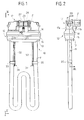
- figure 1 is a front elevation view of an armored resistor with protective switching means according to an embodiment of the invention;
- figure 2 is a front elevation view, taken along the arrows II-II of figure 1;
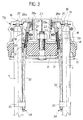
- figure 3 is an enlarged-scale partially sectional view, taken along the plane III-III of figure 2, showing the switching means in closed position;
- figure 4 is an enlarged-scale view of a detail of figure 3, illustrating the switching means in open position after intervention of the heat-sensitive means;
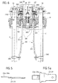
- figures 5 and 5a are respectively a side view and a plan view of the fixed contacts of the switching means of figure 3;
- figure 6 is a sectional view, similar to figure 3, illustrating the device according to another embodiment of the invention, with the switching means in closed position;
- figure 7 is an enlarged-scale view of a detail of figure 6, illustrating the switching means in open position.
- With reference to figures 1 to 5, the
reference numeral 10 generally designates the armored resistor; thereference numeral 11 designates the protective sheath of the resistor; and thereference numeral 12 designates the element for fixing the resistor to the tank of the washing machine. - In a per se known manner, the
fixing element 12 is constituted by two superimposedmetallic flanges elastomeric gasket 15 is inserted; said gasket is expanded, in order to provide a retention and sealing action against the edges of the seat formed in the wall of the tank, by the tightening of abolt 16, which clamps the plates against each other. - According to the invention, a
hollow container 17 is arranged above theplate 14 and is constituted by a cell made of an elastically insulating polymeric material, which is formed by two half-shells Seats 18 for containing the end portions of thesheath 11, and a pair ofcylindrical guides 20 are provided in the half-shells of thecell 17; said guides are arranged respectively adjacent to theseats 18, with respect to which they are inclined at an angle of approximately 8o. Atray 21 is also formed on the outer face of the half-shell 17b and contains and protects three male Faston connectors 22-23-24 mutually spaced by a distance of 10 mm and suitable to receive corresponding female connectors fitted on the power supply cables and the ground cable. Thetray 21 has a keyed insertion profile, and the profile of the female connectors is correspondingly keyed in order to avoid connection errors. - The
power supply connectors shell 17b and form, with theirtab connector 23, suitable to receive a female connector connected to the ground cable, extends with anoffset portion 23a entering aslot 25 formed on theflange 14 of thefixing element 12 and is in electrical contact with said flange, to which it is connected by riveting or upsetting. Corresponding movingcontacts fixed contacts corresponding terminal 19 of the resistor; its other end is forced into elastic contact engagement with the correspondingfixed contact - In order to ensure effective elastic engagement between the fixed and the moving contacts, said moving contacts are substantially S-shaped and their end is connected to the
corresponding terminal 19 of the resistor by means of a forced fit providing, in a known manner, for a hole having a smaller diameter than that of said connector and is surrounded by radial cuts forming corresponding elastically deformable sectors which, when the connector is pressed, prevent the axial sliding of the moving contact. - According to the invention, a
corresponding pusher element 27 is aligned with each moving contact 26 below it; said pusher element is constituted by a steatite cylinder slideably contained in the correspondingcylindrical guide 20. Eachpusher element 27 rests on theterminal disk 30 of acorresponding traction element 31 slideably contained in a respectivetubular guide 32. Apre-loaded spring 33 is interposed between thedisk 30 and the correspondingadjacent end 32a of thetubular guide 32 and is kept under tension by a fusible-weld connection 34, coupling the other end of the traction element 31 (the one opposite to the disk 30) to the corresponding end of thetubular guide 32. Said guide sealingly passes through thefixing element 12 and extends for a convenient length along thesheath 11 of the resistor, against which it is clamped by means of ametallic strap 35. Thefusible weld 34 is made of a fusible alloy with a melting point of approximately 200oC, with a variation of plus or minus 10oC depending on the nature and proportion of the metals composing the alloy. - It is easily understandable that for temperatures below this value, the described safety system remains inactive (figure 3), whereas in case of absence of water, when the temperature of the
sheath 11 slightly exceeds 200oC thewelds 34 melt and release thetraction elements 31. This is followed by the sudden extension of thesprings 33 which, by acting on thepushers 27, cause the rapid opening of the corresponding moving contacts 26 (figure 4). Naturally, the tension of thespring 33 is chosen so that it is sufficiently higher than the tension applied by the moving contact lamina 26 on the respective fixed contact, so as to ensure the complete separation of said moving contact from the corresponding fixed contact. Preferably, theend 32a of thetubular guide 32, adjacent to thedisk 30, is cup-shaped, so as to receive anelastomeric gasket 36 on which thespring 33 contrasts, deforming said gasket so that it adheres by forced contact engagement against thetraction element 31 in order to seal against any leakage of water along theguide 32. - In the embodiment of figures 6 and 7, the
moving contacts 260 are constituted by laminae shaped like wire springs which deform elastically by rotating about apivot 261. The free end of said contacts adheres, by elastic contact engagement, to a correspondingfixed contact 240 constituted by the end, folded at right angles, of awing 241 of each Fastonconnector - A
respective pusher element 270, constituted by an oscillating button made of a polymeric material which is subject to the action of apre-loaded spring 330, acts at said free end of the moving contacts. Thepusher 270 is fitted on the end of thefirst arm 311 of alever 310 which can oscillate about afulcrum 312. Thespring 330 is kept under tension by the retaining action of aplate 340, made of a fusible alloy, connecting the end of thesecond arm 313 of thelever 310 to thesheath 11 of the resistor. Thefulcrum 312 of the lever is constituted by a spherical expansion sealingly interposed, so that it can perform limited oscillations, between a hemispherical seat formed in theelastomeric gasket 15 and theouter flange 14 of thefixing element 12. Thesecond arm 313 of thelever 310 passes through thefixing element 12 in a correspondingconical opening 340 of theelastomeric gasket 15 and in aslot 341 of theinternal flange 13, both of which allow the oscillation of the lever. According to this variation, if the temperature of thesheath 11 rises above the preset value, theplates 340 melt, releasing thelevers 310, and thebuttons 270, pushed by thesprings 330, cause the rapid opening of themoving contacts 260. - Naturally, without altering the concept of the invention, the details of execution and the embodiments may be varied extensively with respect to what is described and illustrated by way of non-limitative example without thereby abandoning the scope of the invention.
- Where technical features mentioned in any claim are followed by reference signs, those reference signs have been included for the sole purpose of increasing the intelligibility of the claims and accordingly such reference signs do not have any limiting effect on the scope of each element identified by way of example by such reference signs.
Claims (13)
- Armored electric resistor (10) for washing machines and the like, comprising a tubular resistor protection sheath (11) suitable to be immersed in the washing tank, an element (12) for fixing said sheath to the wall of the tank and heat-sensitive switching means for protection against overheating, characterized in that said switching means include fixed (22a, 24a) and movable (26a, 26b) contacts, normally closed by elastic engagement and supported respectively by the connectors (24, 26) for connection to the power supply line and by the terminals (19) of the resistor, and pusher elements (27) for the quick opening of said contacts, controlled by respective pre-loaded elastic means (33) normally kept under tension by traction elements (31) which are rigidly coupled, so as to prevent movements, by stop elements (34) made of fusible material associated with the sheath (11) of the resistor; when a preset sheath temperature is exceeded, said stop elements (34) melt and release the pre-loaded elastic means (33) which, by acting on the pusher elements (27), open said contacts (22a, 24a, 26a, 26b) and disconnect the resistor.
- Armored electric resistor according to claim 1, characterized in that each pusher element (27) for opening the contacts is constituted by a cylinder made of insulating material resting on a disk (30) provided at the end with a traction element (31) slideably contained in a tubular guide (32) and in that a pre-loaded spring (33) is interposed between the disk (30) and the corresponding end (32a) of said tubular guide (32) and is kept under tension by a fusible-weld connection (34) between the other end of the traction element (31) and the corresponding end of the tubular guide (32); said fusible weld (34) being kept in contact with the sheath (11) of the resistor by a metal strap (35) for heat exchange.
- Armored electric resistor according to claims 1 and 2, characterized in that said fixed (22a, 24a) and movable (26a, 26b) contacts are contained in a hollow container made of insulating material associated with said element (12) for fixing the resistor and formed by mutually opposite half-shells (17a, 17b) which are mutually coupled.
- Armored electric resistor according to claims 1 to 3, characterized in that said half-shells (17a, 17b), which form the hollow container, are internally provided with a pair of containment seats (18) for said terminals (15) of the resistor and with a pair of guides (20) for said movable cylinders (27) made of insulating material, said cylinders guides being inclined with respect to said resistor terminal seats (18).
- Armored electric resistor according to claims 1 to 4, characterized in that one of said half-shells (17b) which forms the hollow container is externally provided with a tray (21) having a keyed insertion profile for the containment and protection of a set of three male Faston-type connectors (22, 23, 24) suitable to receive female connectors with a correspondingly keyed profile which are fitted onto the power supply and ground conductors.
- Armored electric resistor according to claims 1 and 5, characterized in that the Faston connectors (22, 24), suitable to receive the female connectors of the power supply cables, extend inside the hollow container (17a, 17b) and form, with an extension (24a, 26a), the pair of fixed contacts of said switching means.
- Armored electric resistor according to claims 1 and 5, characterized in that the Faston connector (23), suitable to receive the female connector of the ground cable, extends with an offset portion (23a) entering a slot (25) of the upper flange (14) of said fixing element (12), to which it is connected by riveting or upsetting.
- Armored electric resistor according to claim 1, characterized in that the moving contacts (26) of the switching means are formed by elastically flexible laminae having one end rigidly coupled to the corresponding terminal (19) of the resistor (10).
- Armored electric resistor according to claims 1 and 2, characterized in that said end of the tubular guide (32a), adjacent to said disk (30) of said traction element (31), is cup-shaped and contains an elastomeric gasket (36) on which said pre-loaded spring (33) contrasts, deforming said gasket (36) and making it adhere to said traction element (31) in order to seal against water leaks.
- Armored electric resistor according to claim 1 and any one of claims 3 to 8, characterized in that each of said pusher elements (270) for opening said contacts (240, 260) of said switching means is constituted by a button arranged at the end of a first arm (311) of a respective lever (310) which can oscillate about a fulcrum (312) and can rotate about said fulcrum (312) of the lever by a pre-loaded spring (330), kept under tension by a plate (340) made of fusible material connecting the end of a second arm (313) of the lever (310) to the sheath (11) of the resistor; said second lever arm (313) passing through the sheath fixing element (12) so as to form a seal and so that it can oscillate.
- Armored electric resistor according to claim 10, characterized in that the moving contacts (260) of the switching means are formed by elastically flexible laminae shaped like wire springs.
- Armored electric resistor according to claim 10, characterized in that said oscillation fulcrum (312) of said lever (310) is constituted by a spherical expansion sealingly interposed between a hemispherical seat formed in an elastomeric gasket (15) of said sheath fixing element (12) and the outer flange (14) of said fixing element (12).
- Armored electric resistor according to claims 10 and 12, characterized in that said second arm (313) of said lever (310) passes through said sheath fixing element (12), in a corresponding conical opening (340) of an elastomeric gasket (15) of said sheath fixing element (12) and in a slot (341) of an internal flange (13) of said fixing element (12).
Applications Claiming Priority (2)
| Application Number | Priority Date | Filing Date | Title |
|---|---|---|---|
| ITTO920599 | 1992-07-14 | ||
| ITTO920599A IT1257915B (en) | 1992-07-14 | 1992-07-14 | ARMORED ELECTRIC RESISTANCE FOR WASHING MACHINES AND SIMILAR, INCORPORATING THERMAL SENSITIVE MEANS OF PROTECTION AGAINST OVER TEMPERATURES |
Publications (3)
| Publication Number | Publication Date |
|---|---|
| EP0579170A2 true EP0579170A2 (en) | 1994-01-19 |
| EP0579170A3 EP0579170A3 (en) | 1994-02-02 |
| EP0579170B1 EP0579170B1 (en) | 1998-05-20 |
Family
ID=11410606
Family Applications (1)
| Application Number | Title | Priority Date | Filing Date |
|---|---|---|---|
| EP93111199A Expired - Lifetime EP0579170B1 (en) | 1992-07-14 | 1993-07-13 | Armored electric resistor for washing machines, including heat-sensitive switching means for protection against overheating |
Country Status (4)
| Country | Link |
|---|---|
| EP (1) | EP0579170B1 (en) |
| DE (1) | DE69318630T2 (en) |
| ES (1) | ES2116370T3 (en) |
| IT (1) | IT1257915B (en) |
Cited By (2)
| Publication number | Priority date | Publication date | Assignee | Title |
|---|---|---|---|---|
| DE19505621A1 (en) * | 1995-02-18 | 1996-08-22 | Ego Elektro Blanc & Fischer | Overheating protection for electrical heating devices |
| EP2543762A2 (en) | 2008-09-23 | 2013-01-09 | Indesit Company S.p.A. | Method for detecting a submerged or emerged operating condition of an electric resistance used in a washing machine |
Family Cites Families (6)
| Publication number | Priority date | Publication date | Assignee | Title |
|---|---|---|---|---|
| DE654037C (en) * | 1934-02-07 | 1937-12-08 | Voigt & Haeffner Akt Ges | Automatic temperature-dependent switch on electrically heated devices |
| US2213722A (en) * | 1937-12-30 | 1940-09-03 | John E Smith | Electrical heating unit |
| GB686800A (en) * | 1950-08-25 | 1953-01-28 | R E Thompson & Company Sunbury | Improvements in temperature-sensitive safety cut-outs for electric heaters |
| GB704204A (en) * | 1950-12-07 | 1954-02-17 | Simpson Robert | An improved safety device for use with electrical appliances |
| US2778917A (en) * | 1954-03-22 | 1957-01-22 | Sullivan Valve & Engineering Co | Electrical safety control apparatus |
| GB8508051D0 (en) * | 1985-03-28 | 1985-05-01 | Otter Controlls Ltd | Heating elements |
-
1992
- 1992-07-14 IT ITTO920599A patent/IT1257915B/en active IP Right Grant
-
1993
- 1993-07-13 EP EP93111199A patent/EP0579170B1/en not_active Expired - Lifetime
- 1993-07-13 ES ES93111199T patent/ES2116370T3/en not_active Expired - Lifetime
- 1993-07-13 DE DE69318630T patent/DE69318630T2/en not_active Expired - Fee Related
Cited By (3)
| Publication number | Priority date | Publication date | Assignee | Title |
|---|---|---|---|---|
| DE19505621A1 (en) * | 1995-02-18 | 1996-08-22 | Ego Elektro Blanc & Fischer | Overheating protection for electrical heating devices |
| EP2543762A2 (en) | 2008-09-23 | 2013-01-09 | Indesit Company S.p.A. | Method for detecting a submerged or emerged operating condition of an electric resistance used in a washing machine |
| EP3133199A1 (en) | 2008-09-23 | 2017-02-22 | Whirlpool EMEA S.p.A | Method for removing calcareous deposits from an electric resistance |
Also Published As
| Publication number | Publication date |
|---|---|
| ITTO920599A0 (en) | 1992-07-14 |
| DE69318630D1 (en) | 1998-06-25 |
| DE69318630T2 (en) | 1998-09-10 |
| ITTO920599A1 (en) | 1994-01-14 |
| EP0579170A3 (en) | 1994-02-02 |
| ES2116370T3 (en) | 1998-07-16 |
| IT1257915B (en) | 1996-02-16 |
| EP0579170B1 (en) | 1998-05-20 |
Similar Documents
| Publication | Publication Date | Title |
|---|---|---|
| US4288686A (en) | Thermostat for popcorn cooking containers or the like | |
| US4295114A (en) | Thermo-switch | |
| US5367279A (en) | Overcurrent protection device | |
| US4319126A (en) | Temperature dependent electric current-regulator-or-limiting switching element for electrical appliances: especially electrically heated devices | |
| KR970024353A (en) | SAFETY DEVICE FOR USE IN SECONDARY BATTERY | |
| JP2001052583A (en) | Circuit breaker | |
| EP1075701B1 (en) | Improvements relating to the control of electric heating elements | |
| KR20080074117A (en) | Fluid-heating device comprising a thermal fuse | |
| US3924213A (en) | Thermostat | |
| US4054769A (en) | Microwave oven interlock switch safety | |
| EP1312289B1 (en) | A temperature controller for a liquid heater | |
| EP0579170B1 (en) | Armored electric resistor for washing machines, including heat-sensitive switching means for protection against overheating | |
| EP1586102B1 (en) | Improvements relating to the control of electric heating elements | |
| EP0684623B1 (en) | Appliances having resistive elements and thermal protective apparatus used therewith | |
| EP1072048B1 (en) | Improvements relating to thermal controls for electric heating elements | |
| US3995246A (en) | Device for controlling the temperature and protecting against excessive flow of current of electric installations | |
| GB2193563A (en) | Liquid heater | |
| GB2381385A (en) | Thermal control | |
| US4268813A (en) | Resettable thermal cut-off switch | |
| WO1993016569A1 (en) | Immersion heaters | |
| US5900176A (en) | Protective device for solar hot water systems | |
| GB2153593A (en) | Temperature sensitive safety switch | |
| EP1249851B1 (en) | Improvements relating to the control of electric heating elements | |
| RU2065633C1 (en) | Thermal protective device for electric heating appliance | |
| RU2097823C1 (en) | Temperature controller |
Legal Events
| Date | Code | Title | Description |
|---|---|---|---|
| PUAI | Public reference made under article 153(3) epc to a published international application that has entered the european phase |
Free format text: ORIGINAL CODE: 0009012 |
|
| PUAL | Search report despatched |
Free format text: ORIGINAL CODE: 0009013 |
|
| AK | Designated contracting states |
Kind code of ref document: A2 Designated state(s): DE ES FR GB |
|
| AK | Designated contracting states |
Kind code of ref document: A3 Designated state(s): DE ES FR GB |
|
| 17P | Request for examination filed |
Effective date: 19940725 |
|
| 17Q | First examination report despatched |
Effective date: 19961014 |
|
| GRAG | Despatch of communication of intention to grant |
Free format text: ORIGINAL CODE: EPIDOS AGRA |
|
| GRAG | Despatch of communication of intention to grant |
Free format text: ORIGINAL CODE: EPIDOS AGRA |
|
| GRAH | Despatch of communication of intention to grant a patent |
Free format text: ORIGINAL CODE: EPIDOS IGRA |
|
| GRAH | Despatch of communication of intention to grant a patent |
Free format text: ORIGINAL CODE: EPIDOS IGRA |
|
| GRAA | (expected) grant |
Free format text: ORIGINAL CODE: 0009210 |
|
| AK | Designated contracting states |
Kind code of ref document: B1 Designated state(s): DE ES FR GB |
|
| REF | Corresponds to: |
Ref document number: 69318630 Country of ref document: DE Date of ref document: 19980625 |
|
| ET | Fr: translation filed | ||
| REG | Reference to a national code |
Ref country code: ES Ref legal event code: FG2A Ref document number: 2116370 Country of ref document: ES Kind code of ref document: T3 |
|
| PGFP | Annual fee paid to national office [announced via postgrant information from national office to epo] |
Ref country code: GB Payment date: 19980810 Year of fee payment: 6 |
|
| PLBE | No opposition filed within time limit |
Free format text: ORIGINAL CODE: 0009261 |
|
| STAA | Information on the status of an ep patent application or granted ep patent |
Free format text: STATUS: NO OPPOSITION FILED WITHIN TIME LIMIT |
|
| 26N | No opposition filed | ||
| PG25 | Lapsed in a contracting state [announced via postgrant information from national office to epo] |
Ref country code: GB Free format text: LAPSE BECAUSE OF NON-PAYMENT OF DUE FEES Effective date: 19990713 |
|
| GBPC | Gb: european patent ceased through non-payment of renewal fee |
Effective date: 19990713 |
|
| PGFP | Annual fee paid to national office [announced via postgrant information from national office to epo] |
Ref country code: ES Payment date: 20070628 Year of fee payment: 15 |
|
| PGFP | Annual fee paid to national office [announced via postgrant information from national office to epo] |
Ref country code: DE Payment date: 20070927 Year of fee payment: 15 |
|
| PGFP | Annual fee paid to national office [announced via postgrant information from national office to epo] |
Ref country code: FR Payment date: 20070628 Year of fee payment: 15 |
|
| PG25 | Lapsed in a contracting state [announced via postgrant information from national office to epo] |
Ref country code: DE Free format text: LAPSE BECAUSE OF NON-PAYMENT OF DUE FEES Effective date: 20090203 |
|
| REG | Reference to a national code |
Ref country code: FR Ref legal event code: ST Effective date: 20090331 |
|
| PG25 | Lapsed in a contracting state [announced via postgrant information from national office to epo] |
Ref country code: FR Free format text: LAPSE BECAUSE OF NON-PAYMENT OF DUE FEES Effective date: 20080731 |
|
| REG | Reference to a national code |
Ref country code: ES Ref legal event code: FD2A Effective date: 20080714 |
|
| PG25 | Lapsed in a contracting state [announced via postgrant information from national office to epo] |
Ref country code: ES Free format text: LAPSE BECAUSE OF NON-PAYMENT OF DUE FEES Effective date: 20080714 |