EP0579110B1 - Schaltung für schaltbare Steckdose - Google Patents
Schaltung für schaltbare Steckdose Download PDFInfo
- Publication number
- EP0579110B1 EP0579110B1 EP93110908A EP93110908A EP0579110B1 EP 0579110 B1 EP0579110 B1 EP 0579110B1 EP 93110908 A EP93110908 A EP 93110908A EP 93110908 A EP93110908 A EP 93110908A EP 0579110 B1 EP0579110 B1 EP 0579110B1
- Authority
- EP
- European Patent Office
- Prior art keywords
- relay coil
- switch
- circuit
- relay
- power source
- Prior art date
- Legal status (The legal status is an assumption and is not a legal conclusion. Google has not performed a legal analysis and makes no representation as to the accuracy of the status listed.)
- Expired - Lifetime
Links
Images
Classifications
-
- H—ELECTRICITY
- H02—GENERATION; CONVERSION OR DISTRIBUTION OF ELECTRIC POWER
- H02J—ELECTRIC POWER NETWORKS; CIRCUIT ARRANGEMENTS OR SYSTEMS FOR SUPPLYING OR DISTRIBUTING ELECTRIC POWER; SYSTEMS FOR STORING ELECTRIC ENERGY
- H02J3/00—Circuit arrangements for AC mains or AC distribution networks
- H02J3/26—Arrangements for eliminating or reducing asymmetry in polyphase networks
-
- H—ELECTRICITY
- H01—ELECTRIC ELEMENTS
- H01H—ELECTRIC SWITCHES; RELAYS; SELECTORS; EMERGENCY PROTECTIVE DEVICES
- H01H47/00—Circuit arrangements not adapted to a particular application of the relay and designed to obtain desired operating characteristics or to provide energising current
- H01H47/22—Circuit arrangements not adapted to a particular application of the relay and designed to obtain desired operating characteristics or to provide energising current for supplying energising current for relay coil
- H01H47/226—Circuit arrangements not adapted to a particular application of the relay and designed to obtain desired operating characteristics or to provide energising current for supplying energising current for relay coil for bistable relays
-
- Y—GENERAL TAGGING OF NEW TECHNOLOGICAL DEVELOPMENTS; GENERAL TAGGING OF CROSS-SECTIONAL TECHNOLOGIES SPANNING OVER SEVERAL SECTIONS OF THE IPC; TECHNICAL SUBJECTS COVERED BY FORMER USPC CROSS-REFERENCE ART COLLECTIONS [XRACs] AND DIGESTS
- Y02—TECHNOLOGIES OR APPLICATIONS FOR MITIGATION OR ADAPTATION AGAINST CLIMATE CHANGE
- Y02E—REDUCTION OF GREENHOUSE GAS [GHG] EMISSIONS, RELATED TO ENERGY GENERATION, TRANSMISSION OR DISTRIBUTION
- Y02E40/00—Technologies for an efficient electrical power generation, transmission or distribution
- Y02E40/50—Arrangements for eliminating or reducing asymmetry in polyphase networks
Definitions
- the invention relates to a control circuit for controlling a latching relay according to the preamble of claim 1.
- a control circuit of said kind (US-A-3,683,239) a single-pole, double-throw switch is provided to conduct positive or negative polarity to the first end of a solenoid coil, the second end thereof being connected through a second switch to the respective other polarity.
- the second switch changes its position and the current is shut off. Therefore, there is no permanent conducting state of the coil dependent from the position of the first switch, nor is there a neutral position of the first switch.
- one or more branch circuits are wired to distribute electrical power to load devices, such as light fixtures or outlet receptacles.
- load devices such as light fixtures or outlet receptacles.
- the receptacle or fixture is hardwired directly to the branch circuit with power to the device being turned on or off at the device itself.
- a light fixture might include a pull cord for actuating a switch, while a small appliance might include a power switch.
- EP-A-556754 state of the art according to Art. 54(3) EPC, assigned to the assignee hereof, discloses a power switching circuit for selectively and automatically connecting an electrical load to any one of a plurality of branch power circuits. This circuit uses either a manually operated branch circuit selection switch or automatically connecting an electrical load to any one of a plurality of branch power circuits.
- the present invention is intended to improve upon the power switching systems discussed above, in a novel and simple manner.
- the invention is defined in claim 1.
- a control circuit controlling switching of a latching relay having a relay coil and an electrical contact switched by the relay coil.
- the relay coil is latched when connected to a positive polarity voltage source and unlatched when connected to a negative polarity voltage source.
- the control circuit includes a power source developing a voltage at a select potential.
- a first switch is selectively operated to be in a neutral state or an actuated state, the first switch conducting electricity incident to being in the actuated state and not conducting electricity incident to being in the neutral state.
- a second switch is selectively operated to be in a neutral state or an actuated state, the second switch conducting electricity incident to being in the actuated state and not conducting electricity incident to being in the neutral state.
- Circuit means are provided for connecting the first and second switches between the power source and the relay coil so that when the first switch is in the actuated state it conducts electricity to apply the potential of the power source to the relay coil at positive polarity to latch the relay coil, and when the second switch is in the actuated state it conducts electricity to apply the potential of the power source to the relay coil at negative polarity to unlatch the relay coil.
- Current limit means electrically connected between the second switch and the relay coil limit current conducted to unlatch the relay coil.
- the current limit means comprises a resistor.
- resistor is in series connection with the second switch circuit.
- the first and second switch circuits together comprise a three-position switch having a movable contact and two fixed contacts.
- the first switch circuit consists of the first fixed contact and the movable contact with the first switched circuit being in the neutral state when the movable contact is remote from the first fixed contact and the actuated state when the movable contact is in contact with the first fixed contact.
- the second switch circuit consists of the second fixed contact and the movable contact, and the second switch circuit is in the neutral state when the movable contact is remote from the second fixed contact and in the actuated state when the movable contact is in contact with the second fixed contact.
- the first and second switch circuits each comprises a switching transistor.
- the first and second switch circuits each comprises a pair of switching transistors connected to opposite sides of the relay coil.
- a first transistor of the first switch circuit connects a first side of the relay coil to a high side of the power source and a second transistor of the first switch circuit connects a second side of the relay coil to a low side of the power source
- a first transistor of the second switch circuit pair connects the second side of the relay coil to the high side of the power source and a second transistor of the second switch circuit connects the first side of the relay coil to a low side of the power source.
- first and second switch circuits are connected to provide an H-bridge circuit.
- a switched receptacle comprising a power source developing a voltage at a select potential.
- a latching relay has a relay coil and an electrical contact switched by the relay coil, the relay coil being latched when connected to a positive polarity voltage source and unlatched when connected to a negative polarity voltage source.
- An outlet receptacle is connected in series with the electrical contact to the power source.
- a first switch circuit is selectively operated to be in a neutral state or an actuated state, the first switch circuit conducting electricity incident to being in the actuated state and not conducting electricity incident to being in the neutral state.
- a second switch circuit is selectively operated to be in a neutral state or an actuated state, the second switch circuit conducting electricity incident to being in the actuated state and not conducting electricity incident to being in the neutral state.
- Circuit means are provided for connecting the first and second switch circuits between the power source and the relay coil, so that when the first switch circuit is in the actuated state it conducts electricity to apply the potential of the power source to the relay coil at positive polarity to latch the relay coil, and when the second switch circuit is in the actuated state it conducts electricity to apply the potential of the power source to the relay coil at negative polarity to unlatch the relay coil.
- Current limit means are electrically connected to the second switch circuit for limiting current conducted to unlatch the relay coil.
- a switched receptacle comprising a power source developing a voltage at a select potential and a latching relay having a relay coil and an electrical contact switched by the relay coil, the relay coil being latched when connected to a positive polarity voltage source and unlatched when connected to a negative polarity voltage source.
- An outlet receptacle is connected in series with the electrical contact to the power source.
- An H-bridge switching circuit is connected between the power source and the relay coil.
- Control means control operation of the H-bridge switching circuit between a set mode and a reset mode, the set mode comprising controlling the H-bridge switching circuit to apply the potential of the power source to the relay coil at positive polarity to latch the relay coil.
- the reset mode comprises controlling the H-bridge switching circuit to apply the potential of the power source to the relay coil at negative polarity to unlatch the relay coil.
- Current limit means operatively connected to the H-bridge circuit limits current conducted to unlatch the relay coil.
- the disclosed subject matter insures that a flux density in the set mode is no greater than that which is needed to actuate the latching relay while allowing the latch to remain in the actuated position even if this power is terminated.
- Current limiting is provided for resetting so that zero flux density results when unlatching.
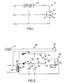
- the switched receptacle 10 includes an outlet receptacle 12 of conventional construction.
- the outlet receptacle 12 includes a first input connection 14, a second input connection 16 and a third input connection 18.
- These three input connections 14, 16 and 18 receive the prongs of a conventional three-prong plug (not shown).
- the outlet receptacle 12 is used for supplying power to the plug from a conventional source of AC power, illustrated by terminals labeled L, G and N.
- the terminal L represents the high side of the power source
- the terminal N the low side of the power source
- the terminal G is ground.
- the terminal N is connected to the second input connection 16.
- the terminal G is connected to the third input connection 18.
- the terminal L is connected to the first input connection 14 via a control block 20.
- control block 20 includes suitable circuitry, described below, for controlling application of power to the outlet receptacle 12. Although not shown, the control block 20 could be used for selectively applying power to a light fixture or other type loading device, as necessary or desired. Moreover, the control block 20 can also be used for selectively connecting the second input connection 16 to the N terminal as specified in EP-A-556 754.
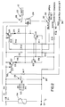
- a schematic diagram illustrates the control 20 according to a first embodiment of the invention.
- the control 20 includes a latching relay 22 having a relay coil 24 and an electrical contact 26 switched by the relay coil 24.
- the relay coil 24 is latched when connected to a positive polarity voltage source and unlatched when connected to a negative polarity voltage source.
- the electrical contact 26 is connected between the L terminal and the load 12 for selectively applying power to the same.
- the latching relay 22 is permanently magnetized so that upon actuation by a relatively high current of positive polarity an included plunger is magnetically retained in an actuated position to close the contact 26.
- a current limit is provided so that zero flux density results after unlatching the latching relay 22.
- the control circuit 20 includes a power supply circuit 28, an H-bridge switching circuit 30 and control circuit 32.
- the power supply circuit 28 is connected to the 120 volt power source terminals L and N. Particularly, a surge protector 34 is connected across the inputs to protect the control circuit 20.
- a half-wave rectifier D1 rectifies the AC power.
- a voltage divider consisting of resistors R1, R2, R3, R4, R5 and R6, along with a filter capacitor C1, develop a DC voltage of approximately 24 volts across the capacitor C1 for powering the latching relay coil 24.
- the H-bridge circuit 30 is used for controlling polarity of power supplied from the power supply circuit 28 to the latching relay 22.
- the H-bridge circuit 30 includes PNP transistors Q2 and Q5 having their emitters connected to a high side of the power supply 28.
- the collector of the transistor Q2 is connected via a diode D3 to a high side of the relay coil 24 and via a voltage divider comprising resistors R8 and R9 to the neutral terminal N.
- the junction between the resistors R8 and R9 is connected to the base of an NPN transistor Q4 having its collector connected to a low side of the latching relay coil 24.
- the emitter of the transistor Q4 is connected to the junction of a resistor R14 and capacitor C2 connected across the power supply 28.
- the capacitor C2 supplies energy to drive the relay coil 24.
- the resistor R14 decouples the capacitor C2 from the H-bridge switching circuit 30.
- the collector of the transistor Q5 is connected via a diode D5 and current limiting resistor R13 to the low side of the latching relay coil 24.
- the collector of the transistor Q5 is also connected to a voltage divider consisting of resistors R10 and R11 to the negative terminal N.
- the junction between the resistors R10 and R11 is connected to the base of an NPN transistor Q3.
- a collector of the transistor Q3 is connected to the high side of the relay coil 24.
- the emitter of the transistor Q3 is connected to the junction between the capacitor C2 and the resistor R14.
- the H-bridge switching circuit 30 is remotely controlled by a suitable circuitry as desired.
- a suitable circuitry as desired.
- the control circuit 32 includes a set input terminal 36, a reset terminal 38 and a common terminal 40.
- the common terminal 40 is connected via resistors R15 and R16 to the negative terminal N.
- the set terminal 36 is connected via current limit resistors R17 and R7 to the base of the transistor Q2.
- the reset terminal 38 is connected via resistors R12 and R18 to the base of the transistor Q5.
- control 20 The operation of the control 20 is described assuming that in its initial state the latching relay 22 is unlatched.
- the remote controlling circuit may be operated in any known manner for providing electrical connection between the switch common terminal 40 and the set terminal 36. Doing so switches the transistor Q2 to on, which in turn through the resistor R8 turns the transistor Q4 on. This connects the high side of the relay coil 24 to the high side of the power source 28 via the transistor Q2 and the low side of the relay coil 24 to the low side of the power supply 28 through the transistor Q4.
- the positive polarity current level is controlled such that the relationship with the relay coil 24 is sufficient that the positive ampere turns will create a flux density to hold the relay coil latch even after termination of power. As such, only a momentary actuation of the set terminal 36 is required.
- the reset terminal 38 is connected by the remote controlling circuit to the common terminal 40 to turn the transistor Q5 on.
- the transistor Q5 connects the low side of the latching relay coil 24 to the high side of the power supply 28.
- the transistor Q5 also drives the transistor Q3 via the resistor R10 to connect the high side of the relay coil to the low side of the power supply 28 to provide negative polarity power across the relay coil 24.
- the current is limited by the current limit resistor R13 so that the negative ampere turns will create a zero flux density to reverse the latch.
- the current limit resistor R13 prevents an unwanted negative flux density in the relay coil 24.
- a control 50 according to an alternative embodiment of the invention is illustrated.
- the control 50 includes a latching relay 52 having a relay coil 54 and electrical contact 56.
- the latching relay 52 is similar to the latching relay 22 discussed above relative to Fig. 2.
- the electrical contact 56 is used for selectively providing power from a power terminal L to a load in the form of the outlet receptacle 12, see Fig. 1.
- the control 50 includes a power supply circuit 58 and a selector switch 60.
- the power supply circuit 58 includes a transformer 62 having a primary winding 64 connected across power terminals L and N.
- the transformer 62 includes a secondary winding 66.
- the transformer 62 in the illustrated embodiment steps the nominal primary voltage, 120 volts AC, to 18 volts AC across the secondary winding 66.
- a high side of the secondary winding 66 is connected to a forward biased diode 68 to a first fixed contact 70 of the selector switch 60.
- a filter capacitor 72 is connected between the low side of the secondary winding 66 and the junction between the diode 68 and first fixed contact 70.
- a reverse biased diode 74 is also connected to the high side of the secondary winding 66 and via a current limit resistor 76 to a second fixed contact 78 of the selector switch 60.
- a filter capacitor 80 is connected between the low side of the secondary winding 66 and the junction between the diode 74 and current limit resistor 76.
- the selector switch 60 comprises a single pole double throw center off selector switch having a movable contact 82 normally spaced from the fixed contacts 70 and 78.
- the movable contact 82 is connected to a high side of the relay coil 54.
- the low side of the relay coil 54 is connected to the low side of the secondary winding 66.
- the movable contact 82 is moved from the center, neutral position to an actuated position in contact with the first fixed contact 70. This connects the relay coil 54 to the source of positive polarity power to latch the relay coil 54, as discussed above.
- the relay 52 remains latched after the movable contact 82 returns to the central, neutral position and the contact 56 remains closed.
- the movable contact 82 is momentarily positioned in contact with the second fixed contact 78 to provide negative polarity power connected across the relay coil 54 to unlatch the same and open the electrical contact 56.
- the current limit resistor 76 insures that a zero flux density is provided in the latching relay 52, as above.
- a latching relay is latched or set by applying a positive polarity DC voltage across its coil and is unlatched to reset by applying a negative polarity DC voltage across its coil.
- a flux density is provided in the set position which is no greater than that which is needed to actuate the latching relay while allowing the relay to remain latched in the actuated position even if power is terminated.
- a specific ampere turn results in zero flux density owing to the current limit resistor so that the latch relay can be pulled back to its open position when reset without a negative flux density being created.
- a switched power receptacle including a control circuit controlling switching of a latching relay which limits current conducted to unlatch the relay.
Landscapes
- Engineering & Computer Science (AREA)
- Power Engineering (AREA)
- Details Of Connecting Devices For Male And Female Coupling (AREA)
- Relay Circuits (AREA)
Claims (8)
- Steuerschaltung (20; 50) zur Steuerung eines bipolaren Relais (22; 52), das eine Relaisspule (24; 54) und einen elektrischen Kontakt (26; 56) aufweist und von einer Art ist, daß, wenn die erste Seite der Spule (24; 54) mit positiver Polarität verbunden wird, das Relais einrastet und, wenn die erste Seite mit negativer Polarität verbunden wird, ausrastet, mit folgenden Merkmalen der Steuerschaltung (20, 50):eine Stromquelle (28; 58), die eine Spannung mit einem vorgewählten Potential abgibt;ein Wählschalter (32; 60), der bestimmt, ob positive oder negative Polarität mit der ersten Seite der Relaisspule (24) verbunden wird;Schaltungsmittel (D3, D5; 68, 74) zur Verbindung der Stromquelle (28, 58) mit der Relaisspule (24, 54); undeine Strombegrenzungseinrichtung (R13; 76) zur Begrenzung des zum Ausrasten der Relaisspule (24) geführten Stromes,dadurch gekennzeichnet,daß der Wahlschalter (32, 58) drei Stellungen aufweist,nämlich eine neutrale Stellung,eine erste betätigte Stellung undeine zweite betätigte Stellung,daß ein erster Schaltkreis (R7, Q2, R8, R9, Q4; 70, 82) durch den Wahlschalter (32, 58) selektiv betätigt wird, um in einen leitenden Zustand zum Einrasten des Relais (22, 52) zu gelangen, wenn der Wahlschalter in seiner ersten betätigten Stellung ist, sowie in einen nichtleitenden Zustand, wenn der Wahlschalter in seiner neutralen Stellung ist, unddaß ein zweiter Schaltkreis (R18, Q5, R10, R11, Q3; 78, 82), der die Strombegrenzungseinrichtung (R13; 76) enthält, durch den Wahlschalter (32, 58) selektiv betätigt wird, um in einen leitenden Zustand zum Ausrasten des Relais (22, 52) zu gelangen, wenn der Wahlschalter in seiner zweiten betätigten Stellung ist, und in einen nichtleitenden Zustand, wenn der Wahlschalter in seiner neutralen Stellung steht.
- Steuerschaltung nach Anspruch 1,
dadurch gekennzeichnet, daß die
Strombegrenzungseinrichtung einen Widerstand (R13, 76) enthält. - Steuerschaltung nach Anspruch 1 oder 2,
dadurch gekennzeichnet, daß die Stromquelle (28; 56)
Kondensatoreinrichtungen (C1, C2; 72, 80) enthält, die zwischen Leitungen von positiver und negativer Polarität geschaltet sind. - Steuerschaltung nach einem der Ansprüche 1 bis 3,
dadurch gekennzeichnet, daß die ersten und zweiten
Schaltkreise jeweils einen Schalttransistor (Q2, Q3) aufweisen. - Steuerschaltung nach einem der Ansprüche 1 bis 4,
dadurch gekennzeichnet, daß die ersten und zweiten
Schaltkreise jeweils ein Paar von Schalttransistoren (Q2, Q4 und Q3, Q5) enthalten, die mit der ersten und zweiten Seite, also den entgegengesetzten Seiten der Relaisspule (24), verbunden sind. - Steuerschaltung nach einem der Ansprüche 1 bis 5,
dadurch gekennzeichnet, daß die ersten und zweiten
Schaltkreise zur Bildung einer H-Brückenschaltung (30) miteinander verbunden sind. - Steuerschaltung nach Anspruch 5 oder 6,
dadurch gekennzeichnet, daß der erste Transistor (Q2) des ersten Schaltkreispaares die erste Seite der Relaisspule (24) mit positiver Polarität der Stromquelle (28) und der zweite Transistor (Q4) des ersten Schaltkreises die zweite Seite der Relaisspule (24) mit negativer Polarität der Stromquelle (28) verbinden und daß der erste Transistor (Q3) des zweiten Schaltkreispaares die zweite Seite der Relaisspule (24) mit der positiven Polarität der Stromquelle (28) und der zweite Transistor (Q5) des zweiten Schaltkreises die erste Seite der Relaisspule (24) mit der negativen Polarität der Stromquelle (28) verbinden. - Kombination der Steuerschaltung (20) gemäß einem der Ansprüche 1 bis 7 und einer geschalteten Dose (12) in Serie mit dem elektrischen Kontakt (26; 56).
Applications Claiming Priority (2)
| Application Number | Priority Date | Filing Date | Title |
|---|---|---|---|
| US07/914,964 US5345360A (en) | 1992-02-18 | 1992-07-16 | Switched receptacle circuit |
| US914964 | 1992-07-16 |
Publications (2)
| Publication Number | Publication Date |
|---|---|
| EP0579110A1 EP0579110A1 (de) | 1994-01-19 |
| EP0579110B1 true EP0579110B1 (de) | 1996-10-09 |
Family
ID=25435012
Family Applications (1)
| Application Number | Title | Priority Date | Filing Date |
|---|---|---|---|
| EP93110908A Expired - Lifetime EP0579110B1 (de) | 1992-07-16 | 1993-07-08 | Schaltung für schaltbare Steckdose |
Country Status (3)
| Country | Link |
|---|---|
| US (1) | US5345360A (de) |
| EP (1) | EP0579110B1 (de) |
| DE (1) | DE69305261T2 (de) |
Families Citing this family (6)
| Publication number | Priority date | Publication date | Assignee | Title |
|---|---|---|---|---|
| KR100801042B1 (ko) * | 2005-09-02 | 2008-02-11 | 김선영 | 자동전원차단콘센트 |
| EP1929591A4 (de) * | 2005-09-02 | 2013-04-03 | Kim Sun Young | Steckerbuchse mit automatischem standby-stromausschalten |
| TWI460582B (zh) * | 2009-10-13 | 2014-11-11 | Sget Corp | Wisdom Learning Control Method of Standby Power Saving Controller |
| US20110095728A1 (en) | 2009-10-28 | 2011-04-28 | Superior Communications, Inc. | Method and apparatus for recharging batteries in a more efficient manner |
| DE102012208122B4 (de) * | 2012-05-15 | 2013-12-24 | Siemens Aktiengesellschaft | Schaltschütz |
| US10396556B2 (en) * | 2014-10-20 | 2019-08-27 | Q Factory 33 Llc | 120VAC to 240VAC power converter, adapter and methods of use |
Family Cites Families (10)
| Publication number | Priority date | Publication date | Assignee | Title |
|---|---|---|---|---|
| US3273039A (en) * | 1963-04-24 | 1966-09-13 | Fox Prod Co | Polarity correcting circuits |
| US3562602A (en) * | 1967-12-13 | 1971-02-09 | Northern Electric Co | Control circuit and method of control for latching relay |
| US3686508A (en) * | 1970-11-13 | 1972-08-22 | Clairmont D Arave | Momentary impulse control |
| US3683239A (en) * | 1971-06-17 | 1972-08-08 | Oded E Sturman | Self-latching solenoid actuator |
| US3731179A (en) * | 1972-09-22 | 1973-05-01 | Gen Electric | Adjustable high voltage power supply with output polarity switching |
| DE2753765C2 (de) * | 1976-12-03 | 1986-03-20 | Hitachi, Ltd., Tokio/Tokyo | Relaisansteuerschaltung |
| DE3278957D1 (en) * | 1981-05-22 | 1988-09-29 | Lucas Ind Plc | Relay circuit and relay therefor |
| JPS58121521A (ja) * | 1982-01-13 | 1983-07-19 | オムロン株式会社 | 電子式タイマ装置 |
| GB8507418D0 (en) * | 1985-03-21 | 1985-05-01 | Smiths Industries Plc | Mains signalling networks & systems |
| US5016134A (en) * | 1990-08-08 | 1991-05-14 | Amp Incorporated | Driver circuit for single coil magnetic latching relay |
-
1992
- 1992-07-16 US US07/914,964 patent/US5345360A/en not_active Expired - Fee Related
-
1993
- 1993-07-08 DE DE69305261T patent/DE69305261T2/de not_active Expired - Fee Related
- 1993-07-08 EP EP93110908A patent/EP0579110B1/de not_active Expired - Lifetime
Also Published As
| Publication number | Publication date |
|---|---|
| US5345360A (en) | 1994-09-06 |
| EP0579110A1 (de) | 1994-01-19 |
| DE69305261T2 (de) | 1997-04-30 |
| DE69305261D1 (de) | 1996-11-14 |
Similar Documents
| Publication | Publication Date | Title |
|---|---|---|
| US5406439A (en) | Feedback of relay status | |
| EP0621659B1 (de) | Hysterese in einer Steckeranwesenheitsüberprüfungsschaltung | |
| US5774322A (en) | Three wire power supply circuit | |
| US4833339A (en) | Load control system | |
| US3872319A (en) | Lazy-man type switching circuit | |
| EP1894446B1 (de) | Dimmerschalter für beleuchtungsschaltungen mit einem dreiwegschalter | |
| US7830042B2 (en) | Dimmer switch for use with lighting circuits having three-way switches | |
| US5170068A (en) | Master electrical load control system | |
| US6232675B1 (en) | Power distribution apparatus comprising relay devices for controlling current flow along power paths of the power distribution apparatus | |
| US20080129124A1 (en) | Hybrid electrical switching device | |
| US5237207A (en) | Master electrical load control system | |
| AU707589B2 (en) | Techniques for controlling remote lamp loads | |
| EP0579110B1 (de) | Schaltung für schaltbare Steckdose | |
| US5359486A (en) | Method and circuit for synchronization of relay operation | |
| US5418679A (en) | Circuit for overriding the cripple mode so that the relay remains latched | |
| JPH1146U (ja) | 電力切り換え回路を有するソケット | |
| US4213059A (en) | Power switching circuit | |
| US4112313A (en) | Timer control arrangement for use with a wall switch | |
| KR100326960B1 (ko) | 단권변압기의강압비제어장치 | |
| US3979599A (en) | Operatively interlocked electronic system | |
| US7280337B2 (en) | Circuit breaker including a non-mechanical, electronic status or control circuit | |
| NO158480B (no) | Styrekobling for et belysningsanlegg. | |
| US7102253B2 (en) | MOSFET based, high voltage, electronic relays for AC power switching and inductive loads | |
| US5539261A (en) | Mechanical alternate action to electrical pulse converter | |
| KR0179870B1 (ko) | 모터 구동 제어 회로 |
Legal Events
| Date | Code | Title | Description |
|---|---|---|---|
| PUAI | Public reference made under article 153(3) epc to a published international application that has entered the european phase |
Free format text: ORIGINAL CODE: 0009012 |
|
| AK | Designated contracting states |
Kind code of ref document: A1 Designated state(s): DE FR GB IT |
|
| 17P | Request for examination filed |
Effective date: 19940601 |
|
| 17Q | First examination report despatched |
Effective date: 19950503 |
|
| GRAG | Despatch of communication of intention to grant |
Free format text: ORIGINAL CODE: EPIDOS AGRA |
|
| GRAH | Despatch of communication of intention to grant a patent |
Free format text: ORIGINAL CODE: EPIDOS IGRA |
|
| ITF | It: translation for a ep patent filed | ||
| GRAH | Despatch of communication of intention to grant a patent |
Free format text: ORIGINAL CODE: EPIDOS IGRA |
|
| GRAA | (expected) grant |
Free format text: ORIGINAL CODE: 0009210 |
|
| AK | Designated contracting states |
Kind code of ref document: B1 Designated state(s): DE FR GB IT |
|
| ET | Fr: translation filed | ||
| REF | Corresponds to: |
Ref document number: 69305261 Country of ref document: DE Date of ref document: 19961114 |
|
| PLBE | No opposition filed within time limit |
Free format text: ORIGINAL CODE: 0009261 |
|
| STAA | Information on the status of an ep patent application or granted ep patent |
Free format text: STATUS: NO OPPOSITION FILED WITHIN TIME LIMIT |
|
| 26N | No opposition filed | ||
| PGFP | Annual fee paid to national office [announced via postgrant information from national office to epo] |
Ref country code: GB Payment date: 19990614 Year of fee payment: 7 |
|
| PGFP | Annual fee paid to national office [announced via postgrant information from national office to epo] |
Ref country code: FR Payment date: 19990707 Year of fee payment: 7 |
|
| PGFP | Annual fee paid to national office [announced via postgrant information from national office to epo] |
Ref country code: DE Payment date: 19990730 Year of fee payment: 7 |
|
| PG25 | Lapsed in a contracting state [announced via postgrant information from national office to epo] |
Ref country code: GB Free format text: LAPSE BECAUSE OF NON-PAYMENT OF DUE FEES Effective date: 20000708 |
|
| GBPC | Gb: european patent ceased through non-payment of renewal fee |
Effective date: 20000708 |
|
| PG25 | Lapsed in a contracting state [announced via postgrant information from national office to epo] |
Ref country code: FR Free format text: LAPSE BECAUSE OF NON-PAYMENT OF DUE FEES Effective date: 20010330 |
|
| REG | Reference to a national code |
Ref country code: FR Ref legal event code: ST |
|
| PG25 | Lapsed in a contracting state [announced via postgrant information from national office to epo] |
Ref country code: DE Free format text: LAPSE BECAUSE OF NON-PAYMENT OF DUE FEES Effective date: 20010501 |
|
| PG25 | Lapsed in a contracting state [announced via postgrant information from national office to epo] |
Ref country code: IT Free format text: LAPSE BECAUSE OF NON-PAYMENT OF DUE FEES;WARNING: LAPSES OF ITALIAN PATENTS WITH EFFECTIVE DATE BEFORE 2007 MAY HAVE OCCURRED AT ANY TIME BEFORE 2007. THE CORRECT EFFECTIVE DATE MAY BE DIFFERENT FROM THE ONE RECORDED. Effective date: 20050708 |