EP0578908B1 - Medical diagnostic apparatus utilizing line-of-sight detection - Google Patents
Medical diagnostic apparatus utilizing line-of-sight detection Download PDFInfo
- Publication number
- EP0578908B1 EP0578908B1 EP93100563A EP93100563A EP0578908B1 EP 0578908 B1 EP0578908 B1 EP 0578908B1 EP 93100563 A EP93100563 A EP 93100563A EP 93100563 A EP93100563 A EP 93100563A EP 0578908 B1 EP0578908 B1 EP 0578908B1
- Authority
- EP
- European Patent Office
- Prior art keywords
- movement
- subject
- sight
- output
- line
- Prior art date
- Legal status (The legal status is an assumption and is not a legal conclusion. Google has not performed a legal analysis and makes no representation as to the accuracy of the status listed.)
- Expired - Lifetime
Links
- 238000001514 detection method Methods 0.000 title claims description 17
- 230000004424 eye movement Effects 0.000 claims description 52
- 230000004886 head movement Effects 0.000 claims description 51
- 201000010099 disease Diseases 0.000 claims description 15
- 208000037265 diseases, disorders, signs and symptoms Diseases 0.000 claims description 15
- 230000003925 brain function Effects 0.000 claims description 10
- 210000003128 head Anatomy 0.000 description 33
- 208000024827 Alzheimer disease Diseases 0.000 description 26
- 238000005070 sampling Methods 0.000 description 6
- 238000000034 method Methods 0.000 description 5
- 230000004044 response Effects 0.000 description 5
- 208000026106 cerebrovascular disease Diseases 0.000 description 4
- 238000003745 diagnosis Methods 0.000 description 4
- 208000024891 symptom Diseases 0.000 description 4
- 210000005252 bulbus oculi Anatomy 0.000 description 3
- 230000003247 decreasing effect Effects 0.000 description 3
- 230000001419 dependent effect Effects 0.000 description 3
- 210000001508 eye Anatomy 0.000 description 3
- 238000012544 monitoring process Methods 0.000 description 3
- 230000032683 aging Effects 0.000 description 2
- 230000015556 catabolic process Effects 0.000 description 2
- 238000003759 clinical diagnosis Methods 0.000 description 2
- 238000006731 degradation reaction Methods 0.000 description 2
- 238000011161 development Methods 0.000 description 2
- 230000018109 developmental process Effects 0.000 description 2
- 238000010586 diagram Methods 0.000 description 2
- 206010013932 dyslexia Diseases 0.000 description 2
- 230000006870 function Effects 0.000 description 2
- 230000000302 ischemic effect Effects 0.000 description 2
- 210000001152 parietal lobe Anatomy 0.000 description 2
- 238000002310 reflectometry Methods 0.000 description 2
- 206010003062 Apraxia Diseases 0.000 description 1
- 208000017854 Balint syndrome Diseases 0.000 description 1
- 206010008190 Cerebrovascular accident Diseases 0.000 description 1
- 206010012289 Dementia Diseases 0.000 description 1
- 206010039966 Senile dementia Diseases 0.000 description 1
- 208000006011 Stroke Diseases 0.000 description 1
- 230000002159 abnormal effect Effects 0.000 description 1
- 230000001154 acute effect Effects 0.000 description 1
- 230000002490 cerebral effect Effects 0.000 description 1
- 230000001149 cognitive effect Effects 0.000 description 1
- 230000006735 deficit Effects 0.000 description 1
- 239000003814 drug Substances 0.000 description 1
- 238000013399 early diagnosis Methods 0.000 description 1
- 230000000694 effects Effects 0.000 description 1
- 238000007689 inspection Methods 0.000 description 1
- 230000003557 neuropsychological effect Effects 0.000 description 1
- 230000008569 process Effects 0.000 description 1
- 230000004434 saccadic eye movement Effects 0.000 description 1
- 238000000926 separation method Methods 0.000 description 1
- 230000009466 transformation Effects 0.000 description 1
- 230000000007 visual effect Effects 0.000 description 1
Images




Classifications
-
- A—HUMAN NECESSITIES
- A61—MEDICAL OR VETERINARY SCIENCE; HYGIENE
- A61B—DIAGNOSIS; SURGERY; IDENTIFICATION
- A61B5/00—Measuring for diagnostic purposes; Identification of persons
- A61B5/103—Measuring devices for testing the shape, pattern, colour, size or movement of the body or parts thereof, for diagnostic purposes
- A61B5/11—Measuring movement of the entire body or parts thereof, e.g. head or hand tremor or mobility of a limb
-
- A—HUMAN NECESSITIES
- A61—MEDICAL OR VETERINARY SCIENCE; HYGIENE
- A61B—DIAGNOSIS; SURGERY; IDENTIFICATION
- A61B3/00—Apparatus for testing the eyes; Instruments for examining the eyes
- A61B3/10—Objective types, i.e. instruments for examining the eyes independent of the patients' perceptions or reactions
- A61B3/113—Objective types, i.e. instruments for examining the eyes independent of the patients' perceptions or reactions for determining or recording eye movement
-
- A—HUMAN NECESSITIES
- A61—MEDICAL OR VETERINARY SCIENCE; HYGIENE
- A61B—DIAGNOSIS; SURGERY; IDENTIFICATION
- A61B5/00—Measuring for diagnostic purposes; Identification of persons
- A61B5/40—Detecting, measuring or recording for evaluating the nervous system
- A61B5/4076—Diagnosing or monitoring particular conditions of the nervous system
- A61B5/4088—Diagnosing of monitoring cognitive diseases, e.g. Alzheimer, prion diseases or dementia
-
- G—PHYSICS
- G16—INFORMATION AND COMMUNICATION TECHNOLOGY [ICT] SPECIALLY ADAPTED FOR SPECIFIC APPLICATION FIELDS
- G16H—HEALTHCARE INFORMATICS, i.e. INFORMATION AND COMMUNICATION TECHNOLOGY [ICT] SPECIALLY ADAPTED FOR THE HANDLING OR PROCESSING OF MEDICAL OR HEALTHCARE DATA
- G16H15/00—ICT specially adapted for medical reports, e.g. generation or transmission thereof
-
- A—HUMAN NECESSITIES
- A61—MEDICAL OR VETERINARY SCIENCE; HYGIENE
- A61B—DIAGNOSIS; SURGERY; IDENTIFICATION
- A61B5/00—Measuring for diagnostic purposes; Identification of persons
- A61B5/68—Arrangements of detecting, measuring or recording means, e.g. sensors, in relation to patient
- A61B5/6801—Arrangements of detecting, measuring or recording means, e.g. sensors, in relation to patient specially adapted to be attached to or worn on the body surface
- A61B5/6802—Sensor mounted on worn items
- A61B5/6803—Head-worn items, e.g. helmets, masks, headphones or goggles
-
- G—PHYSICS
- G16—INFORMATION AND COMMUNICATION TECHNOLOGY [ICT] SPECIALLY ADAPTED FOR SPECIFIC APPLICATION FIELDS
- G16H—HEALTHCARE INFORMATICS, i.e. INFORMATION AND COMMUNICATION TECHNOLOGY [ICT] SPECIALLY ADAPTED FOR THE HANDLING OR PROCESSING OF MEDICAL OR HEALTHCARE DATA
- G16H40/00—ICT specially adapted for the management or administration of healthcare resources or facilities; ICT specially adapted for the management or operation of medical equipment or devices
- G16H40/60—ICT specially adapted for the management or administration of healthcare resources or facilities; ICT specially adapted for the management or operation of medical equipment or devices for the operation of medical equipment or devices
- G16H40/63—ICT specially adapted for the management or administration of healthcare resources or facilities; ICT specially adapted for the management or operation of medical equipment or devices for the operation of medical equipment or devices for local operation
Definitions
- the present invention relates to a medical diagnostic apparatus utilizing line-of-sight detection. More specifically, the present invention relates to a medical diagnostic apparatus which enables diagnoses of diseases related to brain function such as dementia by detecting line-of-sight of a subject.
- the number of patients suffering from Alzheimer's disease is estimated to be four million in the United States and about a million in Japan.
- senile dementia such as cerebrovascular disease popular among Japanese
- the cause of Alzheimer's disease is not known, and much effort has made to find the cause so as to enable early diagnosis and early medical treatment.
- Hachinski's ischemic score has been proposed as a method of discriminating these two diseases. According to this ischemic score, a point is given dependent on whether or not the patient has an anamnesis of apoplexy, cerebral infraction or the like and if the points exceeds a prescribed number, it is determined as the cerebrovascular disease, and otherwise it is determined to be Alzheimer's disease. However, discrimination is still difficult by this method if the patient has no such anamnesis.
- a medical diagnosis apparatus which utilizes the detection of line-of-sight for diagnosing dyslexia.
- This apparatus comprises eye movement detectors, a CRT for presenting a target to a subject and a computer which is responsive to the output of the eye movement detectors while the subject is gazing at a target which is presented to him.
- the line-of-sight of the subject is calculated in order to determine whether or not the subject is suffering from dyslexia.
- the results of these calculations are outputted in form of e.g. a graph on a suitable output means such as a CRT display, a storage disk, a strip chart or a printer.
- such a device does not utilize the information comprised in the components of the velocity of the spacial movement of the line-of-sight in order to determine whether the subject is suffering from a disease which is related to brain function.
- whether or not the disease is related to the brain function is determined referring to the spatial movement of the line-of-sight when the subject is gazing the target, so that the movement of the line-of-sight particular in diseases related to brain function such as Alzheimer's disease can be easily recognized, which is useful for medical and clinical diagnosis and rehabilitation.
- head movement of the subject is detected, and referring to the head movement and the movement of the line-of-sight while the subject is gazing at the presented target, whether or not the disease is related to brain function is determined.
- targets are presented from different angles with respect to the subject.
- rotation velocity component and parallel velocity component of the head movement of the subject are calculated and output in response to the detected head movement, and in addition, the eye ball velocity component is calculated and output in response to the eye movement of the subject.
- Fig. 1 is a schematic block diagram of one embodiment of the present invention.
- Fig. 2 shows an example in which the eye movement detecting portion and the head movement detecting portion shown in Fig. 1 are attached to goggles.
- Fig. 3 shows a specific example of the head movement detecting portion.
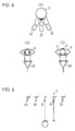
- Fig. 4 shows a specific example of the eye movement detecting portion.
- Fig. 5 is an illustration of a target presenting apparatus shown in Fig. 1.
- Fig. 6 shows a principle of the head coordinate system with the subject being the center.
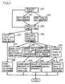
- Fig. 7 is a flow chart showing specific operation of one embodiment of the present invention.
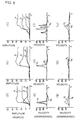
- Fig. 8 shows an example of display in accordance with one embodiment of the present invention, which shows an example of a locus of movement of the line-of-sight provided by adding the head movement and the eye movement from 0° to 25° targets.
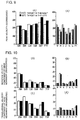
- Fig. 9 shows an example of display of the peak velocity of the eye movement.
- Fig. 10 shows rotation velocity component and the average velocity component of the head movement.
- Fig. 11 shows an example of an amplitude of the line-of-sight provided by adding the head movement and the eye movement between gazing points.
- Fig. 12 shows an example of head share of the head movement with respect to the line-of-sight sight provided by adding the head movement and the eye movement between gazing points.
- Fig. 1 is a schematic block diagram of one embodiment of the present invention.
- an eye movement detecting portion 2 detects eye movement of a subject, and the detection output thereof is applied to a calculating portion 1.
- a head movement detecting portion 3 detects the head movement of the subject, and the detection output thereof is applied to the calculating portion 1.
- the calculating portion 1 calculates the movement of the line-of-sight noting the movement of the line-of-sight of the subject to provide the velocity of the eye movement, the velocity of the head movement, the amplitude of the line-of-sight, characteristics of the movement of the line-of-sight, and the ratio of eye movement and of head movement in the movement of the line-of-sight, that is, head share, and the results are output to an output portion 4.
- a CRT display for example, is used as the output portion 4.
- the calculating portion 1 provides an instruction to the target presenting apparatus 5 to have the target presented to the subject.
- Fig. 2 shows an example in which the eye movement detecting portion 2 and the head movement detecting portion 3 shown in Fig. 1 are attached to goggles
- Fig. 3 shows a specific example of the head movement detecting portion
- Fig. 4 shows a specific example of the eye movement detecting portion 2.
- the goggles 8 shown in Fig. 2 which the subject wares have the eye movement detection portion 2 attached to a lower portion of one side thereof.
- the eye movement detecting portion 2 includes a light emitting diode 21 provided at the center and the photodiodes 22 and 23 provided on both sides thereof as shown in Fig. 4.
- a light emitting diode radiating infrared rays having relatively wide directivity of about ⁇ 21° is used as the light emitting diode 21, while ones having acute directivity of about ⁇ 10° are used as the photodiodes 22 and 23.
- the light beam emitted from the light emitting diode 21 to the eye ball 9 is reflected from the iris of the eye 10 and from the white of the eye 11 with different reflectivity, and the difference in reflectivity is amplified by an operational amplifier 25. If the difference is calculated, a horizontal output (left and right) is obtained as shown in Fig. 4(b), and if the sum is calculated by an operation amplifier 24, a vertical (up and down) output is obtained as shown in Fig. 4(c).
- the head movement detecting portion 3 is formed of a magnetic sensor as shown in Fig. 3. More specifically, the head movement detecting portion 3 includes a orthogonal coil serving as a source 31 and an orthogonal coil serving as a sensor 32. In accordance with an instruction from a control portion 33, a driving circuit 34 drives the orthogonal coil of the source 31 to generate a magnetic field. When the subject wearing the head movement detecting portion 3 moves, a voltage is induced in the sensor 32, which voltage is detected by the detecting circuit 35, the detected output therefrom is calculated by the control portion 33, and thus data corresponding to the movement of the head is output.
- Fig. 5 is an illustration of the target presenting apparatus 5 shown in Fig. 1.
- a target board is provided at a position apart by 1m from the subject, on which board light emitting diodes 51 - 55 are attached shifted by 25° from each other with respect to the subject at the center.
- the light emitting diodes 51 - 55 are lit in the order of 0° ⁇ 25° ⁇ 0° ⁇ 50° ⁇ 0° ⁇ -25° ⁇ 0° ⁇ -50° ⁇ 0° in response to the instructions from the calculating portion 1 shown in Fig. 1.
- Fig. 6 is an illustration showing the principle of the head coordinate system with the subject being the center.
- the head coordinate system detected by the head movement detecting portion 3 will be described.
- the head coordinate system includes two systems, that is, XY coordinate system realized by the translational movement of the subject with respect to the object of monitoring such as shown in Fig. 6(a), and a polar coordinate system based on the rotation movement of the head such as shown in Fig. 6(b).
- the amount of head movement in respective coordinate systems are defined as (Hx, Hy, Hz), (H ⁇ , H ⁇ , H ⁇ ).
- the direction toward the object of monitoring is represented by the Y axis
- the horizontal movement is represented by the X axis
- the vertical movement is represented by the Z axis, as an example.
- H ⁇ represents the rotation of the X axis, that is, the movement of one's neck upward or downward.
- H ⁇ represents the rotation of the Y axis, that is, the movement of inclining ones neck once from the left shoulder to the right shoulder.
- H ⁇ represents rotation in the Z axis, that is, rotation of one's neck in the left or right direction.
- Fig. 7 is a flow chart showing the operation of one embodiment of the present invention
- Figs. 8 - 12 show examples of display in accordance with one embodiment of the present invention.
- the calculating portion 1 in Fig. 1 have the target presenting apparatus 5 as in the same figure which presents the target to the subject. More specifically, the calculating portion 1 has the light emitting diodes 51 - 55 lit in the order of, for example, 0° ⁇ 25° ⁇ 0° ⁇ 50° ⁇ 0° ⁇ -25° ⁇ 0° ⁇ -50° ⁇ 0° as shown in Fig. 5, successively.
- the eye movement detecting portion 2 detects the eye movement of the subject, applies the data of the eye movement to the calculating portion 1.
- the head movement detecting portion 3 detects the head movement, and applies data of the head movement to the calculating portion 1.
- the calculating portion 1 takes the amount of head movement (Hx, Hy, Hz) and (H ⁇ , H ⁇ , H ⁇ ) of the head coordinate system described above with reference to Fig. 6 as the data of head movement, and in step SP3, it takes the eye coordinate system (Xe, Ye) as the data of the eye movement.
- the calculating portion 1 effects calculation of the equations (1) to (8) described above in each of the sampling periods i, i+1, i+2 ....
- H ⁇ i , H ⁇ i , H ⁇ i , Hx i , Hy i , Hz i , X'e i , Y'e i , Vx i and Vy i in each sampling period are obtained.
- the calculating portion 1 calculates the locus of the line-of-sight, the locus of the eye movement, the locus of the angle of head rotation and the locus of translational movement of the head. More specifically, the calculating portion 1 connects the line-of-sight (Vx i , Vy i ) and (Vx i+1 , Vy i+1 ) in the sampling period i, and calculates the locus of the line-of-sight. Further, the calculating portion 1 connects by the locus the eye movements (X'e i , Y'e i ) and (X'e i+1 , Y'e i+1 ) in the sampling period i, so as to calculate the locus of the eye movement.
- the calculating portion 1 calculates the locus of the angles of the head rotation (H ⁇ i , H ⁇ i ), (H ⁇ i+1 , H ⁇ i+1 ) in the sampling period i, so as to calculate the locus of the angle of the head rotation.
- the calculating portion 1 connects by a locus the translational movements of the head (Ex i , Ey i ) and (Ex i+1 , Ey i+1 ) to provide a locus of the translational movement of the head.
- the calculating portion 1 calculates velocities of various components in step SP6.
- the velocity v 1 of the line-of-sight is calculated by the following equation (9) where Ts represents the sampling period.
- v 1 ⁇ (Vx i+1 - Vx i ) 2 + (Vy i+1 - Vy i ) 2 ⁇ /Ts
- v 2 ⁇ (X'e i+1 - X'e i ) 2 + (Y'e i+1 - Y'e i ) 2 ⁇ /Ts
- v 3 ⁇ (H ⁇ i+1 - H ⁇ i ) 2 + (H ⁇ i+1 - H ⁇ i ) 2 ⁇ /Ts
- v 4 ⁇ (Ex i+1 - Ex i ) 2 + (Ey i+1 - Ey i ) 2 ⁇ /Ts
- the locus a of the line-of-sight, the locus b of the eye movement, the locus c of the angle of head rotation and the locus d of the translational movement of the head calculated in the above described manner are displayed as shown in Figs. 8(a) - (c) in step SP5, and the respective velocities v 1 - v 4 are displayed as shown in Figs. 8(d) - (i) in step SP7.
- FIG. 8 (a), (d) and (g) show the data of a young healthy person.
- Figs. 8(b), (e) and (h) show the data of an aged healthy person.
- Figs. 8(c), (f) and (i) show data of a patient suffering from Alzheimer's disease.
- Figs. 8(a) - (c) show the locus a of the line-of-sight, the locus b of the eye movement, the locus c of the angle of head rotation and the locus d of the translational movement of the head with the time axis being the abscissa.
- FIG. 8(d), (e) and (f) show the velocity v 1 of the line-of-sight and the velocity V 2 of the eye movement with the time axis being the abscissa.
- Figs. 8(g), (h) and (i) show the velocity v 3 of the angle of head rotation and the velocity v 4 of the translational movement of the head with the time axis being the abscissa.
- the waveform (c+d) indicating the head movement of the patient of Alzheimer's disease is smaller than the one of the young healthy person, and as shown in Fig.
- the peak of the velocity v 1 of the line-of-sight and the peak of the velocity v 2 of the eye movement of the patient of Alzheimer's disease are larger than the young and aged healthy persons. Namely, it is recognized at one sight that the patient cannot reach straight the target but he reaches the target through some steps.
- the calculating portion 1 determines whether the disease comes from advance in age or the disease is Alzheimer's disease, and outputs the result to the output portion 4 in step SP8.
- step SP9 the calculating portion 1 calculates the peak velocity and the average velocity of the movement of the line-of-sight provided by adding samples of the head movement and the eye movement adjacent to each other on time basis, and displays the result at the output portion 4. As a result, the peak velocity is displayed in the manner as shown in Fig. 9 at the output portion 4. Further, in step SP10, the calculating portion 1 compares speed anisotropy of the left and right directions.
- Fig. 9(a) is an example of display of the peak velocities of six young and aged healthy persons, that is, A (24 years old), B (29 years old), C (35 years old), D (58 years old), E (67 years old) and F (75 years old).
- Fig. 9(a) is an example of display of the peak velocities of six young and aged healthy persons, that is, A (24 years old), B (29 years old), C (35 years old), D (58 years old), E (67 years old) and F (75 years old).
- FIG. 9(b) is an example of display of the peak velocities of seven patients suffering from Alzheimer's disease.
- the velocities in the left and right directions of the young and healthy persons are approximately uniform, while the velocity in the right direction is faster by 50°/sec to 100°/sec than the velocity in the left direction in the group of the patients of the Alzheimer's disease. This is used as a reference to discriminate Alzheimer's disease, and the result of discrimination is output to the output portion 4.
- step SP11 the calculating portion 1 calculates the average velocity component of the head movement, and outputs the result to the output portion 4 in the manner shown in Fig. 10.
- Fig. 10 (a) and (c) are examples of the healthy person, and (b) and (d) are examples of a patient suffering from Alzheimer's disease.
- the calculating portion 1 determines whether or not the velocity of the head movement is decreased in step SP12, and discriminates Alzheimer's disease from troubles popular among old persons.
- step SP13 after the gazing point separation, the calculating portion 1 calculates the head movement between gazing points, the eye movement, and the amplitude and head share of the movement of the line-of-sight obtained by adding the head and eye movements, and outputs the result to the output portion 4.
- the results are as shown in Figs. 11 and 12.
- Fig. 11 shows an example of the amplitude of the line-of-sight obtained by adding the head movement and the eye movement between gazing points.
- Fig. 12 shows an example of head share with respect to the line-of-sight obtained by adding the head movement and the eye movement between gazing points.
- step SP14 the calculating portion 1 discriminates a healthy person from a patient of Alzheimer's disease dependent on whether or not the gazing is imperfect.
- the determination of the gazing point is disclosed in, for example, Japanese Patent Laying-Open No. 2-156199 in which the velocity of the line-of-sight is used as a reference.
- the head share is decreased as the age is advanced in case of healthy persons.
- the head share of the patient of the Alzheimer's disease is further decreased and it is as small as 20% or less. Therefore in step SP15, the calculating portion 1 compares the ratio of decrease of the head share, and referring to the ratio of the head share, it determines the advance of the phenomena of aging and the advance of Alzheimer's disease.
- the calculation portion 1 provides the determinations such as shown in the following table 1.
- Table 1 DETERMINATION SHEET Name of Patient (1)Number of Stepwise Eye Movement (2)Anisotropy in velocity in left/right directions (3)Decrease of velocity of Head Movement (4)Imperfect Gazing (5)Decrease of Head Share ABC o o o o o DEF o o x x o XYZ x x o o o
- the doctor can discriminates the advance of the phenomena of aging from the advance of the Alzheimer's disease quickly.
- the output portion 4 shown in Fig. 1 is not limited to a CRT display, and the output may be provided to a telephone circuit through a printer or a modem.
- targets are presented to a subject, the eye movement of the subject at that time is detected, the spatial movement of the line-of-sight of the subject is calculated in response to the detected output and it is determined whether or not the disease is related to the brain function. Therefore, by referring to the movement of the line-of-sight, Alzheimer's disease can be immediately discriminated from the cerebrovascular disease, and this invention is promising in the field of clinical diagnosis and in the field of rehabilitation.
Landscapes
- Health & Medical Sciences (AREA)
- Life Sciences & Earth Sciences (AREA)
- Engineering & Computer Science (AREA)
- Public Health (AREA)
- General Health & Medical Sciences (AREA)
- Medical Informatics (AREA)
- Biomedical Technology (AREA)
- Veterinary Medicine (AREA)
- Animal Behavior & Ethology (AREA)
- Physics & Mathematics (AREA)
- Surgery (AREA)
- Biophysics (AREA)
- Molecular Biology (AREA)
- Heart & Thoracic Surgery (AREA)
- Neurology (AREA)
- Physiology (AREA)
- Pathology (AREA)
- Ophthalmology & Optometry (AREA)
- Human Computer Interaction (AREA)
- Neurosurgery (AREA)
- Developmental Disabilities (AREA)
- Child & Adolescent Psychology (AREA)
- Psychology (AREA)
- Dentistry (AREA)
- Oral & Maxillofacial Surgery (AREA)
- Epidemiology (AREA)
- Primary Health Care (AREA)
- Hospice & Palliative Care (AREA)
- Psychiatry (AREA)
- Eye Examination Apparatus (AREA)
Description
- The present invention relates to a medical diagnostic apparatus utilizing line-of-sight detection. More specifically, the present invention relates to a medical diagnostic apparatus which enables diagnoses of diseases related to brain function such as dementia by detecting line-of-sight of a subject.
- The number of patients suffering from Alzheimer's disease is estimated to be four million in the United States and about a million in Japan. Compared with senile dementia such as cerebrovascular disease popular among Japanese, the cause of Alzheimer's disease is not known, and much effort has made to find the cause so as to enable early diagnosis and early medical treatment. However, it is difficult to discriminate Alzheimer's disease from cerebrovascular disease when there is no typical symptoms. There has been a strong demand of accurate method of discrimination, since development of disease, pharmaceutical treatment and so on are different for these diseases.
- Hachinski's ischemic score has been proposed as a method of discriminating these two diseases. According to this ischemic score, a point is given dependent on whether or not the patient has an anamnesis of apoplexy, cerebral infraction or the like and if the points exceeds a prescribed number, it is determined as the cerebrovascular disease, and otherwise it is determined to be Alzheimer's disease. However, discrimination is still difficult by this method if the patient has no such anamnesis.
- It has been known that neuropsychological symptom which is considered to be an impairment of "tool disfunction" such as visual cognitive disfunction appears from relatively early period of Alzheimer's disease. In view of this fact, Fujii et al. has reported the following analysis carried out by utilizing eye movement. More specifically, a problem of copying a cube on the right side while watching an original of the cube on the left side is presented. Even a patient who is in the initial stage I of Alzheimer's disease and does not show apparent constructional apraxia is reported to show characteristic symptom similar to a so called Balint syndrome; that is, the patient cannot stare at one point, or more specifically, abnormal distribution of gazing point appears, saccade deviated from both the presented cube and the depicted drawing by the patient is generated, or the point of gazing is fixed at the same point for a long period of time. In Alzheimer's disease, it is supposed from MRI (nuclear magnetic periorbital inspection) that there is caused disfunction of parietal lobe which is related to spatial vision. Accordingly, constructional disfunction derived from degradation in function of the rear association areas with the parietal lobe being the center, degradation of function of positional recognition of a target point or recognition of depth derived from disfunction of external spatial vision such as disfunction of eye movement, disfunction of coordinate transformation system between the coordinate of eye movement system and the coordinate of the center of one's body axis, or visual-motor disfunction, is supposed to be a possible cause of the aforementioned symptoms.
- From US 4,889,422 a medical diagnosis apparatus is known which utilizes the detection of line-of-sight for diagnosing dyslexia. However, Alzheimer's disease might in principle also be detectable with such an apparatus. This apparatus comprises eye movement detectors, a CRT for presenting a target to a subject and a computer which is responsive to the output of the eye movement detectors while the subject is gazing at a target which is presented to him. The line-of-sight of the subject is calculated in order to determine whether or not the subject is suffering from dyslexia. The results of these calculations are outputted in form of e.g. a graph on a suitable output means such as a CRT display, a storage disk, a strip chart or a printer.
- However, even though e.g. reading velocity is also considered with such a device when the head is fixed in order to avoid head movements, such a device does not utilize the information comprised in the components of the velocity of the spacial movement of the line-of-sight in order to determine whether the subject is suffering from a disease which is related to brain function.
- From US 4,582,403 a head movement correction technique is known according to which the line-of-sight is corrected for head movement in order to establish the correct eye movement.
- From EP 0 281 717 A1 and from the Proceedings of the annual international conference of the IEEE engineering in medicine and biology society, vol. 13, No. 4, 31/10/91, pp. 1700, 1701 similar apparatuses are known.
- It is the object of the present invention to provide a medical diagnosis apparatus which facilitates diagnosis of diseases related to brain function.
- This object is solved by a medical diagnosis apparatus according to
claim 1. - Further developments of the present invention can be obtained from the subclaims.
- According to the present invention, whether or not the disease is related to the brain function is determined referring to the spatial movement of the line-of-sight when the subject is gazing the target, so that the movement of the line-of-sight particular in diseases related to brain function such as Alzheimer's disease can be easily recognized, which is useful for medical and clinical diagnosis and rehabilitation.
- In a more preferred embodiment of the present invention, head movement of the subject is detected, and referring to the head movement and the movement of the line-of-sight while the subject is gazing at the presented target, whether or not the disease is related to brain function is determined.
- Further, in a preferred embodiment of the present invention, targets are presented from different angles with respect to the subject.
- Further, in a more preferred embodiment of the present invention, rotation velocity component and parallel velocity component of the head movement of the subject are calculated and output in response to the detected head movement, and in addition, the eye ball velocity component is calculated and output in response to the eye movement of the subject.
- The foregoing and other objects, features, aspects and advantages of the present invention will become more apparent from the following detailed description of the present invention when taken in conjunction with the accompanying drawings.
- Fig. 1 is a schematic block diagram of one embodiment of the present invention.
- Fig. 2 shows an example in which the eye movement detecting portion and the head movement detecting portion shown in Fig. 1 are attached to goggles.
- Fig. 3 shows a specific example of the head movement detecting portion.
- Fig. 4 shows a specific example of the eye movement detecting portion.
- Fig. 5 is an illustration of a target presenting apparatus shown in Fig. 1.
- Fig. 6 shows a principle of the head coordinate system with the subject being the center.
- Fig. 7 is a flow chart showing specific operation of one embodiment of the present invention.
- Fig. 8 shows an example of display in accordance with one embodiment of the present invention, which shows an example of a locus of movement of the line-of-sight provided by adding the head movement and the eye movement from 0° to 25° targets.
- Fig. 9 shows an example of display of the peak velocity of the eye movement.
- Fig. 10 shows rotation velocity component and the average velocity component of the head movement.
- Fig. 11 shows an example of an amplitude of the line-of-sight provided by adding the head movement and the eye movement between gazing points.
- Fig. 12 shows an example of head share of the head movement with respect to the line-of-sight sight provided by adding the head movement and the eye movement between gazing points.
- Fig. 1 is a schematic block diagram of one embodiment of the present invention. Referring to Fig. 1, an eye
movement detecting portion 2 detects eye movement of a subject, and the detection output thereof is applied to a calculatingportion 1. A headmovement detecting portion 3 detects the head movement of the subject, and the detection output thereof is applied to the calculatingportion 1. In response to the detection output from the eyemovement detecting portion 2 and the headmovement detecting portion 3 when the subject is gazing at a specific target, the calculatingportion 1 calculates the movement of the line-of-sight noting the movement of the line-of-sight of the subject to provide the velocity of the eye movement, the velocity of the head movement, the amplitude of the line-of-sight, characteristics of the movement of the line-of-sight, and the ratio of eye movement and of head movement in the movement of the line-of-sight, that is, head share, and the results are output to anoutput portion 4. A CRT display, for example, is used as theoutput portion 4. In addition, the calculatingportion 1 provides an instruction to thetarget presenting apparatus 5 to have the target presented to the subject. - Fig. 2 shows an example in which the eye
movement detecting portion 2 and the headmovement detecting portion 3 shown in Fig. 1 are attached to goggles, Fig. 3 shows a specific example of the head movement detecting portion, and Fig. 4 shows a specific example of the eyemovement detecting portion 2. - The
goggles 8 shown in Fig. 2 which the subject wares have the eyemovement detection portion 2 attached to a lower portion of one side thereof. The eyemovement detecting portion 2 includes alight emitting diode 21 provided at the center and thephotodiodes light emitting diode 21, while ones having acute directivity of about ±10° are used as thephotodiodes light emitting diode 21 to theeye ball 9 is reflected from the iris of theeye 10 and from the white of theeye 11 with different reflectivity, and the difference in reflectivity is amplified by anoperational amplifier 25. If the difference is calculated, a horizontal output (left and right) is obtained as shown in Fig. 4(b), and if the sum is calculated by anoperation amplifier 24, a vertical (up and down) output is obtained as shown in Fig. 4(c). - The head
movement detecting portion 3 is formed of a magnetic sensor as shown in Fig. 3. More specifically, the headmovement detecting portion 3 includes a orthogonal coil serving as asource 31 and an orthogonal coil serving as asensor 32. In accordance with an instruction from acontrol portion 33, adriving circuit 34 drives the orthogonal coil of thesource 31 to generate a magnetic field. When the subject wearing the headmovement detecting portion 3 moves, a voltage is induced in thesensor 32, which voltage is detected by the detectingcircuit 35, the detected output therefrom is calculated by thecontrol portion 33, and thus data corresponding to the movement of the head is output. - Fig. 5 is an illustration of the
target presenting apparatus 5 shown in Fig. 1. Referring to Fig. 5, a target board is provided at a position apart by 1m from the subject, on which board light emitting diodes 51 - 55 are attached shifted by 25° from each other with respect to the subject at the center. The light emitting diodes 51 - 55 are lit in the order of 0° → 25° → 0° → 50° → 0° → -25° → 0° → -50° → 0° in response to the instructions from the calculatingportion 1 shown in Fig. 1. - Fig. 6 is an illustration showing the principle of the head coordinate system with the subject being the center. Referring to Fig. 6, the head coordinate system detected by the head
movement detecting portion 3 will be described. The head coordinate system includes two systems, that is, XY coordinate system realized by the translational movement of the subject with respect to the object of monitoring such as shown in Fig. 6(a), and a polar coordinate system based on the rotation movement of the head such as shown in Fig. 6(b). The amount of head movement in respective coordinate systems are defined as (Hx, Hy, Hz), (Hψ, Hφ, Hθ). In this embodiment, the direction toward the object of monitoring is represented by the Y axis, the horizontal movement is represented by the X axis and the vertical movement is represented by the Z axis, as an example. Hφ represents the rotation of the X axis, that is, the movement of one's neck upward or downward. Hθ represents the rotation of the Y axis, that is, the movement of inclining ones neck once from the left shoulder to the right shoulder. Hψ represents rotation in the Z axis, that is, rotation of one's neck in the left or right direction. - The line-of-sight changes by the horizontal movement of the head (Hx, Hy, Hz), and when this movement is changed in the equivalent of rotation angle of the eye ball (Ex, Ey), the following equations are obtained.

- When the neck is inclined by Hθ to the left shoulder or to the right shoulder, the coordinate of the eye movement system rotates. Therefore, the eye movement coordinate system (Xe, Ye) inclined by Hθ must be changed to the coordinate system (Xe', Ye') which is orthogonal to the original object of monitoring.

- The movement of the line-of-sight (Xh, Yh) realized by the head movement is represented by the following equations (5) and (6) derived from the equations (1) and (2).

- Therefore, the movement of the line-of-sight (Vx, Vy) taking the head movement into account is represented by the following equations (7) and (8), from equations (3) to (6).

- By employing the equations (7) and (8) above, the ordinary movement of one's line-of-sight effected by combining head movement and eye movement can be reproduced.
- Fig. 7 is a flow chart showing the operation of one embodiment of the present invention, and Figs. 8 - 12 show examples of display in accordance with one embodiment of the present invention.
- Referring to Figs. 1 - 12, a specific operation of one embodiment of the present invention will be described. In step (simply denoted by SP in the drawings) SP1, the calculating
portion 1 in Fig. 1 have thetarget presenting apparatus 5 as in the same figure which presents the target to the subject. More specifically, the calculatingportion 1 has the light emitting diodes 51 - 55 lit in the order of, for example, 0° → 25° → 0° → 50° → 0° → -25° → 0° → -50° → 0° as shown in Fig. 5, successively. At this time, the eyemovement detecting portion 2 detects the eye movement of the subject, applies the data of the eye movement to the calculatingportion 1. The headmovement detecting portion 3 detects the head movement, and applies data of the head movement to the calculatingportion 1. In step SP2, the calculatingportion 1 takes the amount of head movement (Hx, Hy, Hz) and (Hψ, Hφ, Hθ) of the head coordinate system described above with reference to Fig. 6 as the data of head movement, and in step SP3, it takes the eye coordinate system (Xe, Ye) as the data of the eye movement. In step SP4, the calculatingportion 1 effects calculation of the equations (1) to (8) described above in each of the sampling periods i, i+1, i+2 .... Thus, Hψi, Hφi, Hθi, Hxi, Hyi, Hzi, X'ei, Y'ei, Vxi and Vyi in each sampling period are obtained. - In step SP5, the calculating
portion 1 calculates the locus of the line-of-sight, the locus of the eye movement, the locus of the angle of head rotation and the locus of translational movement of the head. More specifically, the calculatingportion 1 connects the line-of-sight (Vxi, Vyi) and (Vxi+1, Vyi+1) in the sampling period i, and calculates the locus of the line-of-sight. Further, the calculatingportion 1 connects by the locus the eye movements (X'ei, Y'ei) and (X'ei+1, Y'ei+1) in the sampling period i, so as to calculate the locus of the eye movement. Further, the calculatingportion 1 calculates the locus of the angles of the head rotation (Hψi, Hφi), (Hψi+1, Hφi+1) in the sampling period i, so as to calculate the locus of the angle of the head rotation. The calculatingportion 1 connects by a locus the translational movements of the head (Exi, Eyi) and (Exi+1, Eyi+1) to provide a locus of the translational movement of the head. - The calculating
portion 1 calculates velocities of various components in step SP6. The velocity v1 of the line-of-sight is calculated by the following equation (9) where Ts represents the sampling period.
- The velocity v2 of the eye movement is calculated by the following equation (10):

- The velocity v3 of the angle of head rotation is calculated by the following equation (11):

- The velocity v4 of the translational movement of the head is calculated by the following equation (12):

- The locus a of the line-of-sight, the locus b of the eye movement, the locus c of the angle of head rotation and the locus d of the translational movement of the head calculated in the above described manner are displayed as shown in Figs. 8(a) - (c) in step SP5, and the respective velocities v1 - v4 are displayed as shown in Figs. 8(d) - (i) in step SP7.
- Referring to Fig. 8, (a), (d) and (g) show the data of a young healthy person. Figs. 8(b), (e) and (h) show the data of an aged healthy person. Figs. 8(c), (f) and (i) show data of a patient suffering from Alzheimer's disease. Figs. 8(a) - (c) show the locus a of the line-of-sight, the locus b of the eye movement, the locus c of the angle of head rotation and the locus d of the translational movement of the head with the time axis being the abscissa. Figs. 8(d), (e) and (f) show the velocity v1 of the line-of-sight and the velocity V2 of the eye movement with the time axis being the abscissa. Figs. 8(g), (h) and (i) show the velocity v3 of the angle of head rotation and the velocity v4 of the translational movement of the head with the time axis being the abscissa. As is apparent from Fig. 8(c), the waveform (c+d) indicating the head movement of the patient of Alzheimer's disease is smaller than the one of the young healthy person, and as shown in Fig. 8(f), the peak of the velocity v1 of the line-of-sight and the peak of the velocity v2 of the eye movement of the patient of Alzheimer's disease are larger than the young and aged healthy persons. Namely, it is recognized at one sight that the patient cannot reach straight the target but he reaches the target through some steps. Dependent on whether the stepwise eye movement seen from Figs. 8(a) - (c) or the number of peaks of the velocity of the eye movement as can be seen from Figs. 8(d) - (f) is two or more with the average of the young healthy person being 1, the calculating
portion 1 determines whether the disease comes from advance in age or the disease is Alzheimer's disease, and outputs the result to theoutput portion 4 in step SP8. - In step SP9, the calculating
portion 1 calculates the peak velocity and the average velocity of the movement of the line-of-sight provided by adding samples of the head movement and the eye movement adjacent to each other on time basis, and displays the result at theoutput portion 4. As a result, the peak velocity is displayed in the manner as shown in Fig. 9 at theoutput portion 4. Further, in step SP10, the calculatingportion 1 compares speed anisotropy of the left and right directions. Fig. 9(a) is an example of display of the peak velocities of six young and aged healthy persons, that is, A (24 years old), B (29 years old), C (35 years old), D (58 years old), E (67 years old) and F (75 years old). Fig. 9(b) is an example of display of the peak velocities of seven patients suffering from Alzheimer's disease. As is apparent from the comparison between Figs. 9(a) and (b), the velocities in the left and right directions of the young and healthy persons are approximately uniform, while the velocity in the right direction is faster by 50°/sec to 100°/sec than the velocity in the left direction in the group of the patients of the Alzheimer's disease. This is used as a reference to discriminate Alzheimer's disease, and the result of discrimination is output to theoutput portion 4. - In step SP11, the calculating
portion 1 calculates the average velocity component of the head movement, and outputs the result to theoutput portion 4 in the manner shown in Fig. 10. Referring to Fig. 10, (a) and (c) are examples of the healthy person, and (b) and (d) are examples of a patient suffering from Alzheimer's disease. As is apparent from Fig. 10, compared with young and old healthy persons, the patient of Alzheimer's disease have slower average velocity especially in the rotation component of the head movement. Thus, the calculatingportion 1 determines whether or not the velocity of the head movement is decreased in step SP12, and discriminates Alzheimer's disease from troubles popular among old persons. - In step SP13, after the gazing point separation, the calculating
portion 1 calculates the head movement between gazing points, the eye movement, and the amplitude and head share of the movement of the line-of-sight obtained by adding the head and eye movements, and outputs the result to theoutput portion 4. The results are as shown in Figs. 11 and 12. Fig. 11 shows an example of the amplitude of the line-of-sight obtained by adding the head movement and the eye movement between gazing points. Fig. 12 shows an example of head share with respect to the line-of-sight obtained by adding the head movement and the eye movement between gazing points. As is apparent from Fig. 11, there is an undershoot of 20° or more in the case of a patient of Alzheimer's disease as compared with the healthy person with respect to a target of, for example, 50°, which means that the gazing is imperfect. Accordingly, in step SP14, the calculatingportion 1 discriminates a healthy person from a patient of Alzheimer's disease dependent on whether or not the gazing is imperfect. The determination of the gazing point is disclosed in, for example, Japanese Patent Laying-Open No. 2-156199 in which the velocity of the line-of-sight is used as a reference. - As is apparent from Fig. 12, the head share is decreased as the age is advanced in case of healthy persons. However, the head share of the patient of the Alzheimer's disease is further decreased and it is as small as 20% or less. Therefore in step SP15, the calculating
portion 1 compares the ratio of decrease of the head share, and referring to the ratio of the head share, it determines the advance of the phenomena of aging and the advance of Alzheimer's disease. - When the processes in the steps SP1 - SP15 are finished, the
calculation portion 1 provides the determinations such as shown in the following table 1.Table 1 DETERMINATION SHEET Name of Patient (1)Number of Stepwise Eye Movement (2)Anisotropy in velocity in left/right directions (3)Decrease of velocity of Head Movement (4)Imperfect Gazing (5)Decrease of Head Share ABC o o o o o DEF o o x x o XYZ x x o o o - By using such a sheet for determination, referring to the results of Figs. 8 - 12 provided simultaneously, the doctor can discriminates the advance of the phenomena of aging from the advance of the Alzheimer's disease quickly.
- The
output portion 4 shown in Fig. 1 is not limited to a CRT display, and the output may be provided to a telephone circuit through a printer or a modem. - As described above, in accordance with this embodiment of the present invention, targets are presented to a subject, the eye movement of the subject at that time is detected, the spatial movement of the line-of-sight of the subject is calculated in response to the detected output and it is determined whether or not the disease is related to the brain function. Therefore, by referring to the movement of the line-of-sight, Alzheimer's disease can be immediately discriminated from the cerebrovascular disease, and this invention is promising in the field of clinical diagnosis and in the field of rehabilitation.
Claims (6)
- A medical diagnostic apparatus utilizing line-of-sight detection for diagnosing a disease related to brain function by detecting the line-of-sight of a subject, comprising:eye movement detecting means (2) for detecting eye movement of said subject;target presenting means (5) for presenting a target to said subject;calculating means (1) responsive to a detection output from said eye movement detecting means while said subject is gazing at a target presented by said target presenting means for calculating spatial movement of the line-of-sight of said subject; andoutput means (4) for outputting the movement of the line-of-sight calculated by said calculating means and information indicating whether or not the disease is related to the brain function, characterised in that said calculating means (1) also calculate a component of the velocity of the spatial movement of the line-of-sight of said subject to determine whether or not the disease is related to brain function and in that said information is obtained on the basis of said component of the velocity of the line of sight.
- The medical diagnostic apparatus utilizing line-of-sight detection according to claim 1, further comprisinghead movement detecting means for detecting head movement of said subject, whereinsaid calculating means includes means responsive to a detection output from said head movement detecting means while said subject is gazing at the target and to the detection output from said eye movement detecting means for detecting spatial movement of the line-of-sight of said subject to output the result to said output means.
- The medical diagnostic apparatus utilizing line-of-sight detection according to claim 1 or 2, whereinsaid target presenting means includes means (51 - 55) for presenting targets from different angles with respect to said subject.
- The medical diagnostic apparatus utilizing line-of-sight detection according to claim 2 or 3, whereinsaid calculating means includes means responsive to the detection output from said head movement detecting means for calculating rotation velocity component of the head movement of said subject to output the result to said output means.
- The medical diagnostic apparatus according to one of claims 1 to 4, whereinsaid calculating means includes means responsive to the detection output from said head movement detecting means for calculating translational velocity component of the head movement of said subject to output the result to said output means.
- The medical diagnostic apparatus according to one of claims 1 to 5, whereinsaid calculating means includes means responsive to the detection output from said eye movement detecting means for calculating the velocity component of the eye movement of said subject to output the result to said output means.
Applications Claiming Priority (2)
| Application Number | Priority Date | Filing Date | Title |
|---|---|---|---|
| JP4182227A JPH0655203B2 (en) | 1992-07-09 | 1992-07-09 | Medical diagnostic device using line-of-sight detection |
| JP182227/92 | 1992-07-09 |
Publications (3)
| Publication Number | Publication Date |
|---|---|
| EP0578908A2 EP0578908A2 (en) | 1994-01-19 |
| EP0578908A3 EP0578908A3 (en) | 1995-02-22 |
| EP0578908B1 true EP0578908B1 (en) | 1997-07-09 |
Family
ID=16114571
Family Applications (1)
| Application Number | Title | Priority Date | Filing Date |
|---|---|---|---|
| EP93100563A Expired - Lifetime EP0578908B1 (en) | 1992-07-09 | 1993-01-15 | Medical diagnostic apparatus utilizing line-of-sight detection |
Country Status (6)
| Country | Link |
|---|---|
| US (1) | US5311879A (en) |
| EP (1) | EP0578908B1 (en) |
| JP (1) | JPH0655203B2 (en) |
| KR (1) | KR960006650B1 (en) |
| CA (1) | CA2086066C (en) |
| DE (1) | DE69311980T2 (en) |
Families Citing this family (32)
| Publication number | Priority date | Publication date | Assignee | Title |
|---|---|---|---|---|
| US6359601B1 (en) | 1993-09-14 | 2002-03-19 | Francis J. Maguire, Jr. | Method and apparatus for eye tracking |
| US6778150B1 (en) * | 1993-09-14 | 2004-08-17 | Francis J. Maguire, Jr. | Method and apparatus for eye tracking |
| JP3293308B2 (en) * | 1994-03-10 | 2002-06-17 | 三菱電機株式会社 | Person state detection device |
| US6181371B1 (en) * | 1995-05-30 | 2001-01-30 | Francis J Maguire, Jr. | Apparatus for inducing attitudinal head movements for passive virtual reality |
| US7453451B1 (en) | 1999-03-16 | 2008-11-18 | Maguire Francis J Jr | Moveable headrest for viewing images from different directions |
| US5956125A (en) * | 1997-06-19 | 1999-09-21 | Bioprobes, Inc. | System and method for screening for dementia |
| DE19809591A1 (en) * | 1998-03-06 | 1999-09-09 | Neuhof | Apparatus and method for presenting moving or still visual impressions for automatically and comprehensively acquiring many parameters of the viewer |
| US6652458B2 (en) * | 2000-06-20 | 2003-11-25 | The Mclean Hospital Corporation | ADHD detection by eye saccades |
| EP1357831A2 (en) * | 2001-02-09 | 2003-11-05 | Sensomotoric Instruments GmbH | Multidimensional eye tracking and position measurement system |
| WO2002065898A2 (en) * | 2001-02-19 | 2002-08-29 | Fraunhofer-Gesellschaft zur Förderung der angewandten Forschung e.V. | Device and method for determining the viewing direction in terms of a fixed reference co-ordinates system |
| US7959674B2 (en) * | 2002-07-16 | 2011-06-14 | Medtronic, Inc. | Suture locking assembly and method of use |
| JP3598385B2 (en) * | 2002-10-17 | 2004-12-08 | 独立行政法人情報通信研究機構 | Higher brain dysfunction diagnostic device |
| US20090270717A1 (en) | 2008-04-25 | 2009-10-29 | Welch Allyn, Inc. | Apparatus and method for diagnosis of optically identifiable ophthalmic conditions |
| US7708403B2 (en) | 2003-10-30 | 2010-05-04 | Welch Allyn, Inc. | Apparatus and method for diagnosis of optically identifiable ophthalmic conditions |
| US7575321B2 (en) | 2003-10-30 | 2009-08-18 | Welch Allyn, Inc. | Apparatus and method of diagnosis of optically identifiable ophthalmic conditions |
| US8016770B2 (en) | 2004-05-26 | 2011-09-13 | Panasonic Electric Works Co., Ltd. | Cognitive function training unit |
| US20080058681A1 (en) * | 2006-08-30 | 2008-03-06 | Casali Henry Eloy S | Portable system for monitoring the position of a patient's head during videonystagmography tests (VNG) or electronystagmography (ENG) |
| ITRM20070526A1 (en) * | 2007-10-05 | 2009-04-06 | Univ Roma | PROCUREMENT AND PROCESSING OF INFORMATION RELATING TO HUMAN EYE ACTIVITIES |
| KR101032832B1 (en) * | 2009-04-20 | 2011-05-06 | 김종성 | Combustion Method of Complete Combustion High Efficiency Hot Air Fan Using Liquefied Oxygen as Heat Source |
| KR102179931B1 (en) * | 2013-03-11 | 2020-11-18 | 칠드런스 헬스케어 오브 애틀란타, 인크. | Systems and methods for detection of cognitive and developmental conditions |
| IL308285B2 (en) | 2013-03-11 | 2024-11-01 | Magic Leap Inc | System and method for augmented and virtual reality |
| KR102271198B1 (en) * | 2013-03-15 | 2021-06-29 | 매직 립, 인코포레이티드 | Display system and method |
| US10506924B2 (en) * | 2013-04-10 | 2019-12-17 | Auckland Uniservices Limited | Head and eye tracking |
| TWI489320B (en) * | 2013-10-25 | 2015-06-21 | Utechzone Co Ltd | Method and apparatus for marking electronic document |
| JP7123539B2 (en) * | 2017-09-21 | 2022-08-23 | 日清オイリオグループ株式会社 | Diagnosis support information provision device |
| US11231612B2 (en) | 2017-10-26 | 2022-01-25 | Magic Leap, Inc. | Broadband adaptive lens assembly with variable optical power for augmented reality display |
| EP3711680B1 (en) | 2017-11-14 | 2025-01-01 | Osaka University | Cognitive dysfunction diagnostic apparatus and cognitive dysfunction diagnostic program |
| IT201800003484A1 (en) * | 2018-03-13 | 2019-09-13 | Alessandro Florian | SYSTEM AND METHOD FOR THE RE-EDUCATION OF THE OCULO-VESTIBULAR SYSTEM |
| JP2021536592A (en) | 2018-08-31 | 2021-12-27 | マジック リープ, インコーポレイテッドMagic Leap, Inc. | Spatically decomposed dynamic dimming for augmented reality devices |
| CN113544570B (en) | 2019-01-11 | 2025-02-14 | 奇跃公司 | Time-multiplexed display of virtual content at various depths |
| CN110693459B (en) * | 2019-10-31 | 2022-04-29 | 北京乐器研究所 | Application of diagnosing Alzheimer's disease and device for diagnosing Alzheimer's disease |
| CN115315217B (en) | 2020-03-27 | 2026-01-02 | 国立大学法人大阪大学 | Cognitive Impairment Diagnostic Devices and Recording Media for Cognitive Impairment Diagnostic Procedures |
Citations (1)
| Publication number | Priority date | Publication date | Assignee | Title |
|---|---|---|---|---|
| US4582403A (en) * | 1984-03-05 | 1986-04-15 | Weinblatt Lee S | Head movement correction technique for eye-movement monitoring system |
Family Cites Families (7)
| Publication number | Priority date | Publication date | Assignee | Title |
|---|---|---|---|---|
| US4158920A (en) * | 1977-02-23 | 1979-06-26 | Walker Norman K | Method and apparatus for testing for brain dysfunction in a human |
| US4838681A (en) * | 1986-01-28 | 1989-06-13 | George Pavlidis | Method and means for detecting dyslexia |
| US4889422A (en) * | 1986-01-28 | 1989-12-26 | George Pavlidis | Method and means for detecting dyslexia |
| FR2608036B1 (en) * | 1986-12-11 | 1989-03-03 | Inst Nat Sante Rech Med | METHOD FOR DETECTING THE DIRECTION OF LOOKING BY ANALYSIS OF THE ELECTROOCULOGRAPHIC SIGNAL AND DEVICE FOR CARRYING OUT SAID METHOD |
| US4848340A (en) * | 1988-02-10 | 1989-07-18 | Intelligent Surgical Lasers | Eyetracker and method of use |
| JPH02156199A (en) * | 1988-12-08 | 1990-06-15 | Ishikawajima Harima Heavy Ind Co Ltd | Solidification of radioactive waste |
| JPH02164335A (en) * | 1988-12-16 | 1990-06-25 | Konan Camera Kenkyusho:Kk | Eyeball motion analyzing device |
-
1992
- 1992-07-09 JP JP4182227A patent/JPH0655203B2/en not_active Expired - Fee Related
- 1992-12-18 US US07/995,651 patent/US5311879A/en not_active Expired - Fee Related
- 1992-12-22 CA CA002086066A patent/CA2086066C/en not_active Expired - Fee Related
-
1993
- 1993-01-15 DE DE69311980T patent/DE69311980T2/en not_active Expired - Fee Related
- 1993-01-15 EP EP93100563A patent/EP0578908B1/en not_active Expired - Lifetime
- 1993-03-12 KR KR1019930003712A patent/KR960006650B1/en not_active Expired - Fee Related
Patent Citations (1)
| Publication number | Priority date | Publication date | Assignee | Title |
|---|---|---|---|---|
| US4582403A (en) * | 1984-03-05 | 1986-04-15 | Weinblatt Lee S | Head movement correction technique for eye-movement monitoring system |
Also Published As
| Publication number | Publication date |
|---|---|
| JPH0670885A (en) | 1994-03-15 |
| JPH0655203B2 (en) | 1994-07-27 |
| KR940001859A (en) | 1994-02-16 |
| KR960006650B1 (en) | 1996-05-22 |
| US5311879A (en) | 1994-05-17 |
| EP0578908A2 (en) | 1994-01-19 |
| CA2086066A1 (en) | 1994-01-10 |
| CA2086066C (en) | 1996-04-30 |
| DE69311980T2 (en) | 1998-01-02 |
| DE69311980D1 (en) | 1997-08-14 |
| EP0578908A3 (en) | 1995-02-22 |
Similar Documents
| Publication | Publication Date | Title |
|---|---|---|
| US5311879A (en) | Medical diagnostic apparatus utilizing line-of-sight detection | |
| EP0578907B1 (en) | Medical diagnostic apparatus utilizing line-of-sight detection | |
| EP0587976B1 (en) | An apparatus for examining gaze shift in depth direction | |
| US5365941A (en) | Apparatus for detecting small involuntary movement | |
| EP0582772B1 (en) | An apparatus for medical diagnosis of brain diseases | |
| EP0590231B1 (en) | An apparatus for analyzing depth perception | |
| US9439592B2 (en) | Eye tracking headset and system for neuropsychological testing including the detection of brain damage | |
| US6381339B1 (en) | Image system evaluation method and apparatus using eye motion tracking | |
| HK1007412B (en) | An apparatus for medical diagnosis of brain diseases | |
| US20040234103A1 (en) | Method and apparatus for detection of drowsiness and quantitative control of biological processes | |
| JP2001509693A (en) | Visual field inspection method and apparatus | |
| CN109634431B (en) | Media-free floating projection visual tracking interactive system | |
| WO2015051272A1 (en) | Eye movement monitoring of brain function | |
| KR20010041665A (en) | Method and device for evaluating an kinetic pattern | |
| Cherif et al. | An adaptive calibration of an infrared light device used for gaze tracking | |
| KR20150140814A (en) | Head and eye tracking | |
| EP4043943A1 (en) | Gaze detection-based smart glasses display device | |
| Viaud-Delmon et al. | Multisensory integration for spatial orientation in trait anxiety subjects: absence of visual dependence | |
| Eigler et al. | Improving detection of coronary morphological features from digital angiograms. Effect of stenosis-stabilized display. | |
| Komatsu et al. | Behavioral evidence of filling-in at the blind spot of the monkey | |
| Wu et al. | Computerised infrared imaging system for studying thermal activation on the skull following somatic stimulation in small animals | |
| Fujii et al. | Disorganized eye head coordination in Alzheimer's disease |
Legal Events
| Date | Code | Title | Description |
|---|---|---|---|
| PUAI | Public reference made under article 153(3) epc to a published international application that has entered the european phase |
Free format text: ORIGINAL CODE: 0009012 |
|
| AK | Designated contracting states |
Kind code of ref document: A2 Designated state(s): DE FR GB NL SE |
|
| PUAL | Search report despatched |
Free format text: ORIGINAL CODE: 0009013 |
|
| AK | Designated contracting states |
Kind code of ref document: A3 Designated state(s): DE FR GB NL SE |
|
| 17P | Request for examination filed |
Effective date: 19950320 |
|
| 17Q | First examination report despatched |
Effective date: 19960521 |
|
| GRAG | Despatch of communication of intention to grant |
Free format text: ORIGINAL CODE: EPIDOS AGRA |
|
| GRAH | Despatch of communication of intention to grant a patent |
Free format text: ORIGINAL CODE: EPIDOS IGRA |
|
| GRAH | Despatch of communication of intention to grant a patent |
Free format text: ORIGINAL CODE: EPIDOS IGRA |
|
| GRAA | (expected) grant |
Free format text: ORIGINAL CODE: 0009210 |
|
| AK | Designated contracting states |
Kind code of ref document: B1 Designated state(s): DE FR GB NL SE |
|
| ET | Fr: translation filed | ||
| REF | Corresponds to: |
Ref document number: 69311980 Country of ref document: DE Date of ref document: 19970814 |
|
| PLBE | No opposition filed within time limit |
Free format text: ORIGINAL CODE: 0009261 |
|
| STAA | Information on the status of an ep patent application or granted ep patent |
Free format text: STATUS: NO OPPOSITION FILED WITHIN TIME LIMIT |
|
| 26N | No opposition filed | ||
| PGFP | Annual fee paid to national office [announced via postgrant information from national office to epo] |
Ref country code: NL Payment date: 20011220 Year of fee payment: 10 |
|
| REG | Reference to a national code |
Ref country code: GB Ref legal event code: IF02 |
|
| PGFP | Annual fee paid to national office [announced via postgrant information from national office to epo] |
Ref country code: GB Payment date: 20020102 Year of fee payment: 10 |
|
| PGFP | Annual fee paid to national office [announced via postgrant information from national office to epo] |
Ref country code: SE Payment date: 20020124 Year of fee payment: 10 |
|
| PGFP | Annual fee paid to national office [announced via postgrant information from national office to epo] |
Ref country code: FR Payment date: 20020129 Year of fee payment: 10 |
|
| PGFP | Annual fee paid to national office [announced via postgrant information from national office to epo] |
Ref country code: DE Payment date: 20020201 Year of fee payment: 10 |
|
| PG25 | Lapsed in a contracting state [announced via postgrant information from national office to epo] |
Ref country code: GB Free format text: LAPSE BECAUSE OF NON-PAYMENT OF DUE FEES Effective date: 20030115 |
|
| PG25 | Lapsed in a contracting state [announced via postgrant information from national office to epo] |
Ref country code: SE Free format text: LAPSE BECAUSE OF NON-PAYMENT OF DUE FEES Effective date: 20030116 |
|
| PG25 | Lapsed in a contracting state [announced via postgrant information from national office to epo] |
Ref country code: NL Free format text: LAPSE BECAUSE OF NON-PAYMENT OF DUE FEES Effective date: 20030801 Ref country code: DE Free format text: LAPSE BECAUSE OF NON-PAYMENT OF DUE FEES Effective date: 20030801 |
|
| EUG | Se: european patent has lapsed | ||
| GBPC | Gb: european patent ceased through non-payment of renewal fee | ||
| PG25 | Lapsed in a contracting state [announced via postgrant information from national office to epo] |
Ref country code: FR Free format text: LAPSE BECAUSE OF NON-PAYMENT OF DUE FEES Effective date: 20030930 |
|
| NLV4 | Nl: lapsed or anulled due to non-payment of the annual fee |
Effective date: 20030801 |
|
| REG | Reference to a national code |
Ref country code: FR Ref legal event code: ST |