EP0577845B1 - Device for positioning member and excavating direction control device for excavator employing said device - Google Patents
Device for positioning member and excavating direction control device for excavator employing said device Download PDFInfo
- Publication number
- EP0577845B1 EP0577845B1 EP93902509A EP93902509A EP0577845B1 EP 0577845 B1 EP0577845 B1 EP 0577845B1 EP 93902509 A EP93902509 A EP 93902509A EP 93902509 A EP93902509 A EP 93902509A EP 0577845 B1 EP0577845 B1 EP 0577845B1
- Authority
- EP
- European Patent Office
- Prior art keywords
- circumferential surface
- annular member
- inner circumferential
- circular inner
- annular
- Prior art date
- Legal status (The legal status is an assumption and is not a legal conclusion. Google has not performed a legal analysis and makes no representation as to the accuracy of the status listed.)
- Expired - Lifetime
Links
Images




Classifications
-
- E—FIXED CONSTRUCTIONS
- E21—EARTH OR ROCK DRILLING; MINING
- E21B—EARTH OR ROCK DRILLING; OBTAINING OIL, GAS, WATER, SOLUBLE OR MELTABLE MATERIALS OR A SLURRY OF MINERALS FROM WELLS
- E21B7/00—Special methods or apparatus for drilling
- E21B7/04—Directional drilling
- E21B7/06—Deflecting the direction of boreholes
- E21B7/062—Deflecting the direction of boreholes the tool shaft rotating inside a non-rotating guide travelling with the shaft
Definitions
- the present invention relates to a positioning device for positioning a member to be driven such as an operational shaft, a probe or the like, in accordance with the preamble of claim 1.
- a positioning device for positioning a member to be driven such as an operational shaft, a probe or the like, in accordance with the preamble of claim 1.
- Such a device is disclosed in EP-A-0 467 335.
- the present invention specifically relates to a drilling-direction control device for a drilling system for oil wells or the like, wherein harmonic drive mechanisms are utilized to deflect a rotational drill shaft in a direction approximately perpendicular to its rotational axis, to thereby control the drilling direction of a drill bit mounted on the end of the rotational drill shaft.
- the drilling direction of a drill bit In oil well drilling, the drilling direction of a drill bit must be shifted so as to avoid rock beds or the like and continue the drilling operation. Also, in case that the drilling direction of a drill bit falls in a condition deviated from a desired one, it must be controlled so as to adjust the orientation thereof to the desired direction.
- a positioning device is known from EP-A-O 467 335. Both the first and the second annular member have identical shape. The second member is disposed axially spaced from the first member, and a drill shaft to be positioned extends through the center of the circular opening formed in each of the first and the second annular member.
- the purpose of the present invention is to realize a positioning device capable of positioning a member with a high degree of resolution by using a harmonic drive mechanism of the hollow type.
- a specific object of the present invention is to realize a drilling-direction control device for a drilling system such as of an oil well drilling system, which employs harmonic drive mechanisms of the hollow type so that it can be constituted in a compact manner and is capable of controlling a drilling direction with a high degree of resolution.
- a device for positioning a member according to the present invention comprises the features defined in claim 1.
- a positioning device for a drilling system is defined in claim 2.
- a member to be positioned is connected to the second annular member so that it is moved integrally with the center of the circular inner circumferential surface of the second annular member.
- the position of the center of the circular inner circumferential surface of the second annular member can be defined as a sum of vectors representing movements of the centers of the circular inner circumferential surfaces of the respective annular members. Therefore, the first and second annular members are controlled of their rotational angular positions and relative rotation so that the center of the member to be positioned can be positioned at any points within a circle having a radius summed by the amounts of deviation of both circular inner circumferential surfaces.
- a drilling-direction control device for a drilling system employs the above-constituted positioning device to partially deflect a rotational drill shaft of the drilling system, to thereby control the drilling direction. More specifically, the drilling direction control device of the present invention has first and second harmonic drive mechanisms of the hollow type arranged coaxially, wherein the first harmonic drive mechanism is connected with a first annular member and the second harmonic drive mechanism is connected with a second annular member.
- the second annular member has a circular inner circumferential surface which is formed so as to fixedly receive therein the rotational drill shaft of the drilling system.
- the rotational drill shaft is arranged so that it penetrates through the circular inner circumferential surface of the second annular member and hollow portions of the first and second harmonic drive mechanisms.
- Figures 1 to 5 illustrate an embodiment of the present invention, wherein a drilling-direction control device of an oil well drilling system is constituted according to the present invention.
- FIG. 1 illustrates an overall structure of an oil well drilling system of the present embodiment.
- reference numerals 1 and 2 denote an oil well drilling system and a rotational drill shaft thereof, respectively.
- the rotational drill shaft has a drill collar 3 connected coaxially on the end thereof, and a drilling bit 4 is mounted on the end of the drill collar 3.
- the rotational drill shaft 2 is connected of its upper side with a drive unit (not shown) for driving thereof.
- a drilling direction control device 5 is arranged adjacent to an upper side of the drill collar 3 in a manner enclosing the rotational drill shaft 2.
- a shaft retaining mechanism 6 is provided upper side of the drilling direction control device 5 for maintaining the moving direction of a portion of the rotational drill shaft 2 supported thereby in a predetermined direction, usually in the vertical direction.
- FIG. 2 shows a schematic section of the drilling direction control device 5 of the present embodiment.
- the drilling direction control device 5 basically comprises a tubular housing 7 arranged surrounding the rotational drill shaft, hollow type first and second harmonic drive mechanisms 8 and 9 arranged inside of the tubular housing 7 in a manner that they are positioned apart from each other in the vertical direction, and a double eccentric mechanism section 10 positioned between the first and second harmonic drive mechanisms inside the tubular housing 7.
- the double eccentric mechanism section 10 comprises a cylindrical member 11 fixedly mounted on the inner surface of the housing 7, a first annular member 12 rotatably supported inside the circular member 11, and a second annular member 13 rotatably supported inside the first annular member 12.
- the housing 7 is formed on its outer circumferential surface with rotation-preventing projections (not shown) which are designed to penetrate into the inner wall of a wellbore to prevent the housing from rotating during drilling operations.
- the first harmonic drive mechanism 8 has first and second rigid circular splines 81 and 82, a circular flexible spline 83 arranged inside the rigid circular splines 81 and 82, and an elliptical-shaped wave generator 84 arranged inside the circular flexible spline 83.
- the wave generator 84 is comprised by an elliptical-shaped rigid cam plate 841 and a ball bearing mechanism 842 inserted between the cam plate and the flexible circular spline 83.
- the rigid cam plate 841 is formed in its center portion with a hollow portion 841a, through which the rotational drill shaft 2 extends loosely.
- the first rigid circular spline 81 is fixedly mounted on a flange formed integrally on the inner surface of the housing 7.
- the second rigid circular spline 82 is connected to the second annular member 13 positioned innermost of the double eccentric mechanism section 10 so that the spline 82 and the second annular member 13 rotate integrally.
- the wave generator 84 is connected via an electromagnetic clutch mechanism 16 to the rotational drill shaft 2 so that the rotational force from the rotational drill shaft 2 can be transferred to the wave generator 84.
- the second harmonic drive mechanism 9 positioned lower side has a similar structure as that of the first harmonic drive mechanism 8. That is, it has first and second circular rigid splines 91 and 92, a circular flexible spline 93 and an elliptical-shaped wave generator 94.
- the wave generator 94 has a rigid cam plate formed therein with a hollow portion 941a, through which the rotational drill shaft 2 extends loosely.
- the first rigid circular spline 91 is fixedly mounted on the inner surface of the housing 7.
- the second rigid circular spline 92 is connected to the first annular member 12 positioned midst of the double eccentric mechanism section 10 so as to rotate integrally.
- the wave generator 94 is connected to the rotational drill shaft 2 via an electromagnetic clutch mechanism 26 so that the rotational force of the shaft 2 can be transferred to the wave generator 94.
- the outermost cylindrical member 11 of this section 10 has a circular inner circumferential surface 11a centered on the shaft center defined by the above-mentioned shaft retaining mechanism 6, or the rotational axis A of the shaft 2.
- the first annular member 12 has a circular outer circumferential surface 12a supported rotatably by the circular inner circumferential surface 11a via a roller bearing mechanism 17.
- the first annular member 12 is formed therein with a circular inner circumferential surface 12a centered on point B deviated from the rotational axis A of the shaft 2 by a distance "e".
- the second annular member 13 has a circular outer circumferential surface 13a rotatably supported by the circular inner circumferential surface 12b via a roller bearing mechanism 18.
- the second annular member 13 is formed therein with a circular inner circumferential surface 13b centered on point C deviated from the center B of the circular inner circumferential surface 12b by the same distance "e".
- This circular inner circumferential surface 13b rotatably supports the outer surface of the rotational drill shaft 2 via a roller bearing mechanism 19.
- the center of the circular inner circumferential surface supporting the rotational drill shaft 2 can be moved in any direction within a predetermined distance by controlling the rotational angular positions of and relative rotational amount of the first and second annular members 12 and 13.
- the locus of the center B is represented by a circle having a radius e around the center A.
- the circular inner circumferential surface 13b of the second annular member 13 has the center C which is deviated from the center B by a distance "e”
- the locus of the center C is represented by a circle having a radius e around the center B.
- the center C can be moved in a desired potion within a circle having a radius of 2e around the center A. Therefore, the portion of the rotational drill shaft 2 supported by the double eccentric mechanism section 10 can be deflected in any direction on a plane perpendicular to the rotational axis by a distance up to "2e".
- the center of the upper side portion of the rotational drill shaft 2 is supported by the shaft retaining mechanism 6 so that it is maintained on the rotational axis A.
- the end of the shaft 2 is changed of its moving direction (drilling direction) along a line L passing from the center A of the shaft retaining mechanism 6 to the center C of the double eccentric mechanism section 10.
- the center C of the portion of the rotational drill shaft 2 extending through the drilling direction control device 5 can be positioned on the rotational axis A of the shaft 2 where the adjustment of the drilling direction is not required.
- Figure 5 shows schematically a controlling system of the drilling-direction control device 5 for changing the drilling direction as mentioned above.
- reference numeral 200 denotes a host computer unit for overall control of the oil well drilling system 1
- reference numeral 201 is a controller for the drilling-direction control device 5.
- the host computer unit 200 outputs a control signal 202S representing the orientation and angle of the drilling direction, which is supplied to the controller 201.
- the controller 201 has a desired-rotational-position calculating circuit 202 for calculating desired rotational positions of the respective annular members 12 and 13 in accordance with the received control signal 202S.
- the controller 201 also has a real-rotational-position detecting circuit 203 for detecting the real rotational positions of the respective annular members 12 and 13, based on detected signals 211S and 212S from detection units 211 and 212 which are mounted on the annular members 12 and 13. Further, the controller 201 has a drive signal generating circuit 204 which generates drive signals 204S for controllably driving the harmonic drive mechanisms 8 and 9 so that the real rotational positions of the annular members 12 and 13 are brought to desired rotational positions, respectively. The drive signals 204S are supplied to drive control units 213 and 214 for the harmonic drive mechanisms.
- the respective drive control units 213 and 214 control the electromagnetic couplings 16 and 26 to drive the harmonic drive mechanisms 8 and 9, whereby the rigid circular splines 82 and 92, which are output elements of the harmonic drive mechanisms, are rotated to the desired rotational positions and fixed thereto.
- the above-mentioned operation can be carried out in accordance with control programs prestored in the host computer 200.
- a pair of harmonic drive mechanisms of the hollow type are employed to change the rotational angular positions and relative rotation of the first and second annular members 12 and 13, whereby the portion of the rotational drill shaft extending through the circular inner circumferential surface of the second annular member is deflected in any direction on a plane perpendicular to the rotational axis by a predetermined distance. Therefore, drilling direction can be changed in any desired direction.
- the harmonic drive mechanisms utilized for the present embodiment are those of high resolution and responsibility, it is capable of performing drilling direction control with excellent controllability.
- the harmonic drive mechanisms utilized for the present embodiment are of the hollow type, the drilling-direction control device can be assembled around the rotational drill shaft compactly, and therefore it is advantageous that the mounting space for the device is small.
- FIG. 6 and 7 shows a positioning device for a column shaft according to the present invention.
- the positioning device 30 of the present embodiment has a hollow type actuator 31, an output side of which is connected to a double eccentric mechanism section 32 of the same structure as that of the first embodiment.
- the column shaft 33 extends through the actuator 31 and the double eccentric mechanism section 32.
- the actuator 31 is comprised of a cup-shaped harmonic drive mechanism 34 of the hollow type and a hollow type AC servomotor 35 coaxially connected to the harmonic drive mechanism 34.
- the AC servomotor 35 has a hollow output shaft 35a connected to a wave generator 34a of the harmonic drive mechanism 34.
- the lower-speed output element that is, the cup-shaped flexible spline 34b has a flange 34c defining the bottom portion thereof, to which first and second annular members 322 and 323 of the double eccentric mechanism section 32 are connected via first and second electromagnetic couplings 36 and 37, respectively.
- an outermost cylindrical member of the double eccentric mechanism section 32 (corresponding to the cylindrical member 11 of the first embodiment) is formed integrally on the inner surface of a housing 38 of the positioning device.
- the first annular member 322 is rotatably supported on a circular inner circumferential surface 321a of the housing 7 via a roller bearing mechanism 324.
- the first annular member 322 has a circular inner circumferential surface 322b, whose center B is located on a position deviated from the center A of the circular inner circumferential surface 321a by a distance "e”.
- the second annular member 323 is rotatably supported by the first circular inner circumferential surface 322b via a roller bearing mechanism 325.
- the second annular member 323 has a circular inner circumferential surface 323b, whose center C is deviated from the center B of the circular inner circumferential surface 322b by the same distance "e”.
- the first and second electromagnetic couplings 36 and 37 are controlled of their connecting and disconnecting states to adjust the rotational angular positions and relative rotation of the first and second annular members 322 and 323, whereby it is possible to position the circular inner circumferential surface 323b of the second annular member, that is, the center 33a thereof, in any direction within a range of radius 2e around the center A.
- the positioning device of the present invention has the following structure:
- the first annular member is rotatably supported by the circular inner circumferential surface of the circular member
- the second annular member is rotatably supported by the circular inner circumferential surface of the first annular member.
- the circular inner circumferential surface of the first annular member is positioned deviated from the center of the circular member
- the circular inner circumferential surface of the second annular member is also positioned deviated from the center of the circular inner circumferential surface of the first annular member.
- the hollow type harmonic drive mechanism is employed to rotate the first and second annular members with respect to each other.
- a member to be positioned is supported by the circular inner circumferential surface of the second annular member, and the first and second annular members are controllably rotated, whereby the member to be positioned can be located in any direction within a range of a predetermined radius.
- the harmonic drive mechanism employed is of high accuracy and responsibility, positioning of the member can be carried out with excellent controllability and high resolution.
- the hollow structure is employed so as to arrange the member to be positioned in the hollow portion, it is advantageous that the mounting space for the device is small and that the device can be constituted in a compact manner.
- the drilling-direction control device of the present invention employs the above-mentioned positioning device to deflect the rotational drill shaft of the drilling system. Therefore, the rotational shaft can be precisely deflected in any direction perpendicular to the rotational axis thereof. In addition, it is advantageous that the device can be constituted compactly.
Landscapes
- Life Sciences & Earth Sciences (AREA)
- Engineering & Computer Science (AREA)
- Geology (AREA)
- Mining & Mineral Resources (AREA)
- Physics & Mathematics (AREA)
- Environmental & Geological Engineering (AREA)
- Fluid Mechanics (AREA)
- General Life Sciences & Earth Sciences (AREA)
- Geochemistry & Mineralogy (AREA)
- Earth Drilling (AREA)
- Drilling And Boring (AREA)
Abstract
Description
- The present invention relates to a positioning device for positioning a member to be driven such as an operational shaft, a probe or the like, in accordance with the preamble of
claim 1. Such a device is disclosed in EP-A-0 467 335. - The present invention specifically relates to a drilling-direction control device for a drilling system for oil wells or the like, wherein harmonic drive mechanisms are utilized to deflect a rotational drill shaft in a direction approximately perpendicular to its rotational axis, to thereby control the drilling direction of a drill bit mounted on the end of the rotational drill shaft.
- In recent years, such machining process as requiring accurate and fine machining has been increased due to developments of the machine tool technology employing numerical controlling system, IC manufacturing technology and the like. In order to realize a highly accurate machining, the cutting bit or the workpiece have to be precisely brought to a desired position.
- In oil well drilling, the drilling direction of a drill bit must be shifted so as to avoid rock beds or the like and continue the drilling operation. Also, in case that the drilling direction of a drill bit falls in a condition deviated from a desired one, it must be controlled so as to adjust the orientation thereof to the desired direction.
- A positioning device according to the preamble of
claim 1 is known from EP-A-O 467 335. Both the first and the second annular member have identical shape. The second member is disposed axially spaced from the first member, and a drill shaft to be positioned extends through the center of the circular opening formed in each of the first and the second annular member. - The purpose of the present invention is to realize a positioning device capable of positioning a member with a high degree of resolution by using a harmonic drive mechanism of the hollow type.
- A specific object of the present invention is to realize a drilling-direction control device for a drilling system such as of an oil well drilling system, which employs harmonic drive mechanisms of the hollow type so that it can be constituted in a compact manner and is capable of controlling a drilling direction with a high degree of resolution.
- In order to achieve the above purpose, a device for positioning a member according to the present invention, comprises the features defined in
claim 1. - A positioning device for a drilling system is defined in
claim 2. - A member to be positioned is connected to the second annular member so that it is moved integrally with the center of the circular inner circumferential surface of the second annular member. In this condition, by rotating the first and second annular members relative to each other, the position of the center of the circular inner circumferential surface of the second annular member can be defined as a sum of vectors representing movements of the centers of the circular inner circumferential surfaces of the respective annular members. Therefore, the first and second annular members are controlled of their rotational angular positions and relative rotation so that the center of the member to be positioned can be positioned at any points within a circle having a radius summed by the amounts of deviation of both circular inner circumferential surfaces.
- A drilling-direction control device for a drilling system according to the present invention employs the above-constituted positioning device to partially deflect a rotational drill shaft of the drilling system, to thereby control the drilling direction. More specifically, the drilling direction control device of the present invention has first and second harmonic drive mechanisms of the hollow type arranged coaxially, wherein the first harmonic drive mechanism is connected with a first annular member and the second harmonic drive mechanism is connected with a second annular member.
- The second annular member has a circular inner circumferential surface which is formed so as to fixedly receive therein the rotational drill shaft of the drilling system. The rotational drill shaft is arranged so that it penetrates through the circular inner circumferential surface of the second annular member and hollow portions of the first and second harmonic drive mechanisms. With this arrangement, by rotating the first and second annular members relative to each other, the center of the circular inner circumferential surface of the second annular member can be moved in any position within a circle having a predetermined radius as mentioned above. In other words, the portion of the rotational drill shaft supported by the circular inner circumferential surface of the second annular member can be deflected by a certain amount in any direction perpendicular to its rotational axis, whereby the drilling direction can be changed.
-
- Figure 1 is a schematic view of an overall structure of an oil well drilling system according to the present invention;
- Figure 2 is a schematic view of a drilling-direction control device provided to the oil well drilling system of Figure 1;
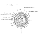
- Figure 3 illustrates a double eccentric mechanism section of the drilling-direction control device of Figure 2;
- Figure 4 shows the operation of the drilling-direction control device of Figure 2;
- Figure 5 is a schematic block diagram of the control system for the drilling-direction control system of Figure 2;
- Figure 6 is a schematic view of a positioning device according to the present invention; and,
- Figure 7 illustrates a double eccentric mechanism section of the positioning device of Figure 6.
- Referring now to the drawings, embodiments of the present invention will be described.
- Figures 1 to 5 illustrate an embodiment of the present invention, wherein a drilling-direction control device of an oil well drilling system is constituted according to the present invention.
- Figure 1 illustrates an overall structure of an oil well drilling system of the present embodiment. In this figure,
reference numerals drill collar 3 connected coaxially on the end thereof, and adrilling bit 4 is mounted on the end of thedrill collar 3. Therotational drill shaft 2 is connected of its upper side with a drive unit (not shown) for driving thereof. A drillingdirection control device 5 is arranged adjacent to an upper side of thedrill collar 3 in a manner enclosing therotational drill shaft 2. Ashaft retaining mechanism 6 is provided upper side of the drillingdirection control device 5 for maintaining the moving direction of a portion of therotational drill shaft 2 supported thereby in a predetermined direction, usually in the vertical direction. - Figure 2 shows a schematic section of the drilling
direction control device 5 of the present embodiment. The drillingdirection control device 5 basically comprises atubular housing 7 arranged surrounding the rotational drill shaft, hollow type first and secondharmonic drive mechanisms tubular housing 7 in a manner that they are positioned apart from each other in the vertical direction, and a doubleeccentric mechanism section 10 positioned between the first and second harmonic drive mechanisms inside thetubular housing 7. The doubleeccentric mechanism section 10 comprises acylindrical member 11 fixedly mounted on the inner surface of thehousing 7, a firstannular member 12 rotatably supported inside thecircular member 11, and a secondannular member 13 rotatably supported inside the firstannular member 12. Thehousing 7 is formed on its outer circumferential surface with rotation-preventing projections (not shown) which are designed to penetrate into the inner wall of a wellbore to prevent the housing from rotating during drilling operations. - The first
harmonic drive mechanism 8 has first and second rigidcircular splines flexible spline 83 arranged inside the rigidcircular splines shaped wave generator 84 arranged inside the circularflexible spline 83. Thewave generator 84 is comprised by an elliptical-shapedrigid cam plate 841 and aball bearing mechanism 842 inserted between the cam plate and the flexiblecircular spline 83. Therigid cam plate 841 is formed in its center portion with ahollow portion 841a, through which therotational drill shaft 2 extends loosely. The first rigidcircular spline 81 is fixedly mounted on a flange formed integrally on the inner surface of thehousing 7. The second rigidcircular spline 82 is connected to the secondannular member 13 positioned innermost of the doubleeccentric mechanism section 10 so that thespline 82 and the secondannular member 13 rotate integrally. In addition, according to the present embodiment, thewave generator 84 is connected via anelectromagnetic clutch mechanism 16 to therotational drill shaft 2 so that the rotational force from therotational drill shaft 2 can be transferred to thewave generator 84. - The second
harmonic drive mechanism 9 positioned lower side has a similar structure as that of the firstharmonic drive mechanism 8. That is, it has first and second circularrigid splines flexible spline 93 and an elliptical-shaped wave generator 94. Thewave generator 94 has a rigid cam plate formed therein with ahollow portion 941a, through which therotational drill shaft 2 extends loosely. The first rigidcircular spline 91 is fixedly mounted on the inner surface of thehousing 7. The second rigidcircular spline 92 is connected to the firstannular member 12 positioned midst of the doubleeccentric mechanism section 10 so as to rotate integrally. Thewave generator 94 is connected to therotational drill shaft 2 via anelectromagnetic clutch mechanism 26 so that the rotational force of theshaft 2 can be transferred to thewave generator 94. - Referring also to Figure 3, the structure of the double
eccentric mechanism section 10 will be described. The outermostcylindrical member 11 of thissection 10 has a circular innercircumferential surface 11a centered on the shaft center defined by the above-mentionedshaft retaining mechanism 6, or the rotational axis A of theshaft 2. The firstannular member 12 has a circular outer circumferential surface 12a supported rotatably by the circular innercircumferential surface 11a via aroller bearing mechanism 17. The firstannular member 12 is formed therein with a circular inner circumferential surface 12a centered on point B deviated from the rotational axis A of theshaft 2 by a distance "e". The secondannular member 13 has a circular outercircumferential surface 13a rotatably supported by the circular innercircumferential surface 12b via aroller bearing mechanism 18. The secondannular member 13 is formed therein with a circular inner circumferential surface 13b centered on point C deviated from the center B of the circular innercircumferential surface 12b by the same distance "e". This circular inner circumferential surface 13b rotatably supports the outer surface of therotational drill shaft 2 via aroller bearing mechanism 19. - According to the double
eccentric mechanism section 10 as constituted above, the center of the circular inner circumferential surface supporting therotational drill shaft 2 can be moved in any direction within a predetermined distance by controlling the rotational angular positions of and relative rotational amount of the first and secondannular members - With reference to Figure 4, since the circular inner
circumferential surface 12b of the firstannular member 12 has the center B which is deviated from the rotational center A of theshaft 2 by a distance "e", the locus of the center B is represented by a circle having a radius e around the center A. Further, since the circular inner circumferential surface 13b of the secondannular member 13 has the center C which is deviated from the center B by a distance "e", the locus of the center C is represented by a circle having a radius e around the center B. Hence, the center C can be moved in a desired potion within a circle having a radius of 2e around the center A. Therefore, the portion of therotational drill shaft 2 supported by the doubleeccentric mechanism section 10 can be deflected in any direction on a plane perpendicular to the rotational axis by a distance up to "2e". - Whereas, in the present embodiment, the center of the upper side portion of the
rotational drill shaft 2 is supported by theshaft retaining mechanism 6 so that it is maintained on the rotational axis A. Thus, as shown in Figure 2, the end of theshaft 2 is changed of its moving direction (drilling direction) along a line L passing from the center A of theshaft retaining mechanism 6 to the center C of the doubleeccentric mechanism section 10. - In the present embodiment, since a degree of deviation of of each of the centers B and C of the circular inner circumferential surfaces formed in the first and second
annular members rotational drill shaft 2 extending through the drillingdirection control device 5 can be positioned on the rotational axis A of theshaft 2 where the adjustment of the drilling direction is not required. - Figure 5 shows schematically a controlling system of the drilling-
direction control device 5 for changing the drilling direction as mentioned above. In this figure,reference numeral 200 denotes a host computer unit for overall control of the oilwell drilling system 1, andreference numeral 201 is a controller for the drilling-direction control device 5. Thehost computer unit 200 outputs a control signal 202S representing the orientation and angle of the drilling direction, which is supplied to thecontroller 201. Thecontroller 201 has a desired-rotational-position calculating circuit 202 for calculating desired rotational positions of the respectiveannular members controller 201 also has a real-rotational-position detecting circuit 203 for detecting the real rotational positions of the respectiveannular members detection units annular members controller 201 has a drivesignal generating circuit 204 which generates drive signals 204S for controllably driving theharmonic drive mechanisms annular members electromagnetic couplings harmonic drive mechanisms circular splines host computer 200. - As mentioned above, according to the drilling-direction control device of the present embodiment, a pair of harmonic drive mechanisms of the hollow type are employed to change the rotational angular positions and relative rotation of the first and second
annular members - Figures 6 and 7 shows a positioning device for a column shaft according to the present invention. The
positioning device 30 of the present embodiment has ahollow type actuator 31, an output side of which is connected to a doubleeccentric mechanism section 32 of the same structure as that of the first embodiment. Thecolumn shaft 33 extends through theactuator 31 and the doubleeccentric mechanism section 32. Theactuator 31 is comprised of a cup-shapedharmonic drive mechanism 34 of the hollow type and a hollowtype AC servomotor 35 coaxially connected to theharmonic drive mechanism 34. TheAC servomotor 35 has ahollow output shaft 35a connected to awave generator 34a of theharmonic drive mechanism 34. The lower-speed output element, that is, the cup-shapedflexible spline 34b has aflange 34c defining the bottom portion thereof, to which first and secondannular members eccentric mechanism section 32 are connected via first and secondelectromagnetic couplings - In the present embodiment, an outermost cylindrical member of the double eccentric mechanism section 32 (corresponding to the
cylindrical member 11 of the first embodiment) is formed integrally on the inner surface of ahousing 38 of the positioning device. Thus, the firstannular member 322 is rotatably supported on a circular innercircumferential surface 321a of thehousing 7 via aroller bearing mechanism 324. The firstannular member 322 has a circular innercircumferential surface 322b, whose center B is located on a position deviated from the center A of the circular innercircumferential surface 321a by a distance "e". The secondannular member 323 is rotatably supported by the first circular innercircumferential surface 322b via aroller bearing mechanism 325. The secondannular member 323 has a circular innercircumferential surface 323b, whose center C is deviated from the center B of the circular innercircumferential surface 322b by the same distance "e". - According to the present embodiment, similar to the first embodiment, the first and second
electromagnetic couplings annular members circumferential surface 323b of the second annular member, that is, the center 33a thereof, in any direction within a range of radius 2e around the center A. - As explained above, the positioning device of the present invention has the following structure: The first annular member is rotatably supported by the circular inner circumferential surface of the circular member, and the second annular member is rotatably supported by the circular inner circumferential surface of the first annular member. Further, the circular inner circumferential surface of the first annular member is positioned deviated from the center of the circular member, and the circular inner circumferential surface of the second annular member is also positioned deviated from the center of the circular inner circumferential surface of the first annular member. Furthermore, the hollow type harmonic drive mechanism is employed to rotate the first and second annular members with respect to each other. Therefore, a member to be positioned is supported by the circular inner circumferential surface of the second annular member, and the first and second annular members are controllably rotated, whereby the member to be positioned can be located in any direction within a range of a predetermined radius. In addition, since the harmonic drive mechanism employed is of high accuracy and responsibility, positioning of the member can be carried out with excellent controllability and high resolution. Further, since the hollow structure is employed so as to arrange the member to be positioned in the hollow portion, it is advantageous that the mounting space for the device is small and that the device can be constituted in a compact manner.
- On the other hand, the drilling-direction control device of the present invention employs the above-mentioned positioning device to deflect the rotational drill shaft of the drilling system. Therefore, the rotational shaft can be precisely deflected in any direction perpendicular to the rotational axis thereof. In addition, it is advantageous that the device can be constituted compactly.
Claims (2)
- A positioning device (5, 30) for a member (2, 33) comprising a cylindrical member (11, 38), a first annular member (12, 322) which is rotatably supported by a circular inner circumferential surface (11a, 321a) of said cylindrical member (11, 28) and has a circular inner circumferential surface (12a, 322b) formed in a position deviated from said circular member (11, 28), a second annular member (13, 323), which has a circular inner circumferential surface (13b, 323b) formed in a position deviated from said circular inner circumferential surface (12a, 322b) of said first annular member (12, 322), and a hollow type harmonic drive mechanism (8, 9; 34) for rotating said first and second annular member (12, 13; 322, 323) about their axes relative to each other, whereby said first and second annular members (12, 13; 322, 323) are rotated relative to each other, to thereby carry out a positioning of said member (2, 33) to be positioned,
characterized in that said second annular member (13, 323) is rotatably supported by said circular inner circumferential surface (12a, 322b) of said first annular member (12, 322), wherein a degree of deviation of said circular inner circumferential surface (12a, 322b) of said first annular member (12, 322b) from said cylindrical member (11, 38) is set equal to that of deviation of said circular inner circumferential surface (13b, 323b) of said second annular member (13, 323) from said first annular member (12, 322), and wherein the member (2, 33) to be positioned is connected to said second annular member (13, 323) so that it moves integrally with a center of said circular inner circumferential surface (13b, 322b) of said second annular member (13, 323). - A device according to claim 1 for a drilling system (1), wherein said harmonic drive mechanism includes first and second harmonic drive mechanisms (8, 9) of the hollow type arranged coaxially, said first harmonic drive mechanism (8) is connected with said first annular member (12), and said second harmonic drive mechanism (9) is connected with said second annular member (13), and wherein a rotational drill shaft (2) of said drilling system (1) as said member to be positioned is arranged so that an outer surface thereof is supported by said circular inner circumferential surface (13b) of said second annular member (13), whereby said first and second annular members (12, 13) are rotated relative to each other to move said circular inner circumferential surface (13b) of said second annular member (13) eccentrically, to thereby deflect a portion of said rotational drill shaft (2) supported by said circular inner circumferential surface (13b) in a predetermined direction.
Applications Claiming Priority (3)
| Application Number | Priority Date | Filing Date | Title |
|---|---|---|---|
| JP32591/92 | 1992-01-23 | ||
| JP4032591A JP2995118B2 (en) | 1992-01-23 | 1992-01-23 | Member positioning device and excavation direction control device for excavator using this device |
| PCT/JP1993/000068 WO1993015300A1 (en) | 1992-01-23 | 1993-01-20 | Device for positioning member and excavating direction control device for excavator employing said device |
Publications (3)
| Publication Number | Publication Date |
|---|---|
| EP0577845A1 EP0577845A1 (en) | 1994-01-12 |
| EP0577845A4 EP0577845A4 (en) | 1994-06-22 |
| EP0577845B1 true EP0577845B1 (en) | 1997-09-24 |
Family
ID=12363108
Family Applications (1)
| Application Number | Title | Priority Date | Filing Date |
|---|---|---|---|
| EP93902509A Expired - Lifetime EP0577845B1 (en) | 1992-01-23 | 1993-01-20 | Device for positioning member and excavating direction control device for excavator employing said device |
Country Status (6)
| Country | Link |
|---|---|
| US (1) | US5353884A (en) |
| EP (1) | EP0577845B1 (en) |
| JP (1) | JP2995118B2 (en) |
| CA (1) | CA2106754C (en) |
| DE (1) | DE69314104T2 (en) |
| WO (1) | WO1993015300A1 (en) |
Cited By (1)
| Publication number | Priority date | Publication date | Assignee | Title |
|---|---|---|---|---|
| US9500031B2 (en) | 2012-11-12 | 2016-11-22 | Aps Technology, Inc. | Rotary steerable drilling apparatus |
Families Citing this family (25)
| Publication number | Priority date | Publication date | Assignee | Title |
|---|---|---|---|---|
| US5875859A (en) * | 1995-03-28 | 1999-03-02 | Japan National Oil Corporation | Device for controlling the drilling direction of drill bit |
| US6340063B1 (en) | 1998-01-21 | 2002-01-22 | Halliburton Energy Services, Inc. | Steerable rotary directional drilling method |
| US7306058B2 (en) | 1998-01-21 | 2007-12-11 | Halliburton Energy Services, Inc. | Anti-rotation device for a steerable rotary drilling device |
| US6234259B1 (en) | 1999-05-06 | 2001-05-22 | Vector Magnetics Inc. | Multiple cam directional controller for steerable rotary drill |
| US6948572B2 (en) * | 1999-07-12 | 2005-09-27 | Halliburton Energy Services, Inc. | Command method for a steerable rotary drilling device |
| CA2474228C (en) | 1999-07-12 | 2008-03-11 | Halliburton Energy Services, Inc. | Directional drilling method for a steerable rotary drilling device |
| US6618604B2 (en) * | 2000-12-28 | 2003-09-09 | Ge Medical Systems Global Technology Company, Llc. | Method and apparatus for correcting the offset induced by field effect transistor photo-conductive effects in a solid state x-ray detector |
| GB0101633D0 (en) | 2001-01-23 | 2001-03-07 | Andergauge Ltd | Drilling apparatus |
| CA2494237C (en) * | 2001-06-28 | 2008-03-25 | Halliburton Energy Services, Inc. | Drill tool shaft-to-housing locking device |
| CA2448723C (en) * | 2003-11-07 | 2008-05-13 | Halliburton Energy Services, Inc. | Variable gauge drilling apparatus and method of assembly thereof |
| US7243739B2 (en) * | 2004-03-11 | 2007-07-17 | Rankin Iii Robert E | Coiled tubing directional drilling apparatus |
| US7798041B2 (en) | 2004-04-15 | 2010-09-21 | Milwaukee Electric Tool Corporation | Miter adjustment assembly for a saw |
| US7287605B2 (en) * | 2004-11-02 | 2007-10-30 | Scientific Drilling International | Steerable drilling apparatus having a differential displacement side-force exerting mechanism |
| NO334262B1 (en) * | 2007-06-20 | 2014-01-20 | 2TD Drilling AS | Device for directional control of drilling tools |
| CN102400644B (en) * | 2010-09-15 | 2014-04-23 | 长江大学 | Stepless adjustable borehole trace control tool |
| CA2749316C (en) * | 2011-08-22 | 2013-08-20 | Devico As | Adjustable eccentric bushing assembly for a wireline-operated directional core barrel drill |
| GB2501461A (en) * | 2012-03-12 | 2013-10-30 | Tercel Ip Ltd | A downhole drive |
| US9134452B2 (en) | 2012-12-10 | 2015-09-15 | Schlumberger Technology Corporation | Weighting function for inclination and azimuth computation |
| US9366087B2 (en) | 2013-01-29 | 2016-06-14 | Schlumberger Technology Corporation | High dogleg steerable tool |
| US9573198B1 (en) | 2013-06-06 | 2017-02-21 | The Boeing Company | Double eccentric positioning apparatus |
| US9068809B1 (en) | 2013-06-06 | 2015-06-30 | The Boeing Company | Quasi-virtual locate/drill/shim process |
| US9932820B2 (en) | 2013-07-26 | 2018-04-03 | Schlumberger Technology Corporation | Dynamic calibration of axial accelerometers and magnetometers |
| WO2015076826A1 (en) | 2013-11-22 | 2015-05-28 | Halliburton Energy Services, Inc. | Down hole harmonic drive transmission |
| WO2015137934A1 (en) * | 2014-03-12 | 2015-09-17 | Halliburton Energy Services, Inc. | Steerable rotary drilling devices incorporating a tilt drive shaft |
| US10521551B2 (en) | 2015-11-16 | 2019-12-31 | The Boeing Company | Methods for shimming flexible bodies |
Family Cites Families (26)
| Publication number | Priority date | Publication date | Assignee | Title |
|---|---|---|---|---|
| US2745635A (en) * | 1953-07-20 | 1956-05-15 | John A Zublin | Apparatus for drilling wells of large radii curved bores |
| US3023821A (en) * | 1955-03-01 | 1962-03-06 | Walter H Etherington | Well tool |
| US2891769A (en) * | 1955-05-02 | 1959-06-23 | Directional Engineering Compan | Directional drilling tool |
| US3042125A (en) * | 1957-06-10 | 1962-07-03 | Duncan Dan Mclean | Full hole deflection tool |
| US2919897A (en) * | 1958-07-07 | 1960-01-05 | Regan Forge & Eng Co | Deflection drilling tool |
| US3043381A (en) * | 1960-05-05 | 1962-07-10 | Jr Branch M Mcneely | Means for controlling directional deviations in a well bore |
| US3713599A (en) * | 1970-04-27 | 1973-01-30 | Western Electric Co | Apparatus for distributing a strand |
| US3650338A (en) * | 1970-05-25 | 1972-03-21 | Branch M Mcneely Jr | Rotary bit guide |
| US4058163A (en) * | 1973-08-06 | 1977-11-15 | Yandell James L | Selectively actuated vibrating apparatus connected with well bore member |
| JPS52105611A (en) * | 1976-03-02 | 1977-09-05 | Komatsu Mfg Co Ltd | Drilling apparatus |
| US4346768A (en) * | 1977-05-12 | 1982-08-31 | Ross Frederick W | Impact device with sinusoidal rotary-to-reciprocative converter |
| US4303135A (en) * | 1977-08-18 | 1981-12-01 | Benoit Lloyd F | Directional drilling sub |
| FR2491989A2 (en) * | 1980-10-13 | 1982-04-16 | Inst Francais Du Petrole | VARIABLE ANGLE ELBOW CONNECTION FOR DIRECTED DRILLING |
| US4436163A (en) * | 1978-12-13 | 1984-03-13 | Black & Decker Inc. | Arrangement for converting rotary motion to reciprocatory motion |
| US4394881A (en) * | 1980-06-12 | 1983-07-26 | Shirley Kirk R | Drill steering apparatus |
| GB2091780B (en) * | 1981-01-23 | 1984-08-01 | Coal Industry Patents Ltd | Drilling methods and equipment |
| DE3219362C1 (en) * | 1982-05-22 | 1983-04-21 | Wirth Maschinen- und Bohrgeräte-Fabrik GmbH, 5140 Erkelenz | Method and device for drilling holes |
| US4506590A (en) * | 1982-07-28 | 1985-03-26 | Shimadzu Coporation | Hydraulic rotary actuator |
| US4632191A (en) * | 1985-04-05 | 1986-12-30 | Gas Research Institute | Steering system for percussion boring tools |
| JPH07116900B2 (en) * | 1986-10-13 | 1995-12-18 | 株式会社日さく | Modified boring equipment |
| JPH0784896B2 (en) * | 1986-11-05 | 1995-09-13 | 株式会社ハーモニック・ドライブ・システムズ | Flexible mesh type gear device |
| JP2503027B2 (en) * | 1987-09-21 | 1996-06-05 | 株式会社ハーモニック・ドライブ・システムズ | Flexible mesh gear |
| CA2002135C (en) * | 1988-11-03 | 1999-02-02 | James Bain Noble | Directional drilling apparatus and method |
| DE4017761A1 (en) * | 1990-06-01 | 1991-12-05 | Eastman Christensen Co | DRILLING TOOL FOR DRILLING HOLES IN SUBSTRATE ROCK INFORMATION |
| JPH0814233B2 (en) * | 1990-07-18 | 1996-02-14 | 株式会社ハーモニック・ドライブ・システムズ | Attitude control device for member and excavation direction control device for excavator |
| JP2697982B2 (en) | 1991-11-29 | 1998-01-19 | 株式会社ハーモニック・ドライブ・システムズ | Excavator direction control device |
-
1992
- 1992-01-23 JP JP4032591A patent/JP2995118B2/en not_active Expired - Lifetime
-
1993
- 1993-01-20 US US08/117,204 patent/US5353884A/en not_active Expired - Lifetime
- 1993-01-20 EP EP93902509A patent/EP0577845B1/en not_active Expired - Lifetime
- 1993-01-20 DE DE69314104T patent/DE69314104T2/en not_active Expired - Lifetime
- 1993-01-20 WO PCT/JP1993/000068 patent/WO1993015300A1/en not_active Ceased
- 1993-01-20 CA CA002106754A patent/CA2106754C/en not_active Expired - Lifetime
Cited By (1)
| Publication number | Priority date | Publication date | Assignee | Title |
|---|---|---|---|---|
| US9500031B2 (en) | 2012-11-12 | 2016-11-22 | Aps Technology, Inc. | Rotary steerable drilling apparatus |
Also Published As
| Publication number | Publication date |
|---|---|
| CA2106754A1 (en) | 1993-07-24 |
| JP2995118B2 (en) | 1999-12-27 |
| CA2106754C (en) | 2001-05-08 |
| DE69314104D1 (en) | 1997-10-30 |
| EP0577845A4 (en) | 1994-06-22 |
| EP0577845A1 (en) | 1994-01-12 |
| WO1993015300A1 (en) | 1993-08-05 |
| JPH05202689A (en) | 1993-08-10 |
| DE69314104T2 (en) | 1998-04-16 |
| US5353884A (en) | 1994-10-11 |
Similar Documents
| Publication | Publication Date | Title |
|---|---|---|
| CA2106754C (en) | Positioning device for a member and drilling-direction control device for a drilling system employing said positioning device | |
| EP0467335B1 (en) | Attitude control device and drilling-direction control device | |
| US6109372A (en) | Rotary steerable well drilling system utilizing hydraulic servo-loop | |
| US6158529A (en) | Rotary steerable well drilling system utilizing sliding sleeve | |
| EP1106777B1 (en) | Method and apparatus for steering a directional drilling tool | |
| RU2317396C2 (en) | Drilling bit unit with lead bit for rotary drilling with drilling direction control | |
| EP1479870B1 (en) | Locking mechanism for drilling direction control device | |
| CN114382408B (en) | Guided drilling equipment | |
| EP0728910B1 (en) | Steerable rotary drilling system | |
| EP1402144B1 (en) | A wellbore directional steering tool | |
| EP0441890B1 (en) | Directional drilling apparatus and method | |
| CN1965143B (en) | Rotary vector gear for use in rotary steerable tools | |
| EP0209318A2 (en) | Control of drilling courses in the drilling of bore holes | |
| JP2697982B2 (en) | Excavator direction control device | |
| US6375542B1 (en) | Hydrostatic spindle unit with automatic self centering of the workpiece | |
| JPH08270369A (en) | Excavator direction control device | |
| CN113073938A (en) | Rotary guide tool | |
| CN116753243A (en) | Dynamic directional rotary guiding force transmission bearing system | |
| GB2325016A (en) | Steerable rotary drilling system | |
| RU2847451C1 (en) | Controlled drilling device | |
| CN111827979B (en) | Attitude monitoring device and method for static offset rotary geosteering system | |
| RU2029048C1 (en) | Deflecting tool for drilling inclined and directional wells | |
| SU1386379A1 (en) | Automatic self-centering rotatable chuck | |
| CN122039977A (en) | Guide hole deflection control device and method in shaft tunneling construction | |
| JPH08270370A (en) | Angle detection device in excavation direction control device of excavator |
Legal Events
| Date | Code | Title | Description |
|---|---|---|---|
| PUAI | Public reference made under article 153(3) epc to a published international application that has entered the european phase |
Free format text: ORIGINAL CODE: 0009012 |
|
| AK | Designated contracting states |
Kind code of ref document: A1 Designated state(s): DE FR GB |
|
| 17P | Request for examination filed |
Effective date: 19940121 |
|
| A4 | Supplementary search report drawn up and despatched | ||
| AK | Designated contracting states |
Kind code of ref document: A4 Designated state(s): DE FR GB |
|
| 17Q | First examination report despatched |
Effective date: 19951005 |
|
| GRAG | Despatch of communication of intention to grant |
Free format text: ORIGINAL CODE: EPIDOS AGRA |
|
| GRAH | Despatch of communication of intention to grant a patent |
Free format text: ORIGINAL CODE: EPIDOS IGRA |
|
| GRAH | Despatch of communication of intention to grant a patent |
Free format text: ORIGINAL CODE: EPIDOS IGRA |
|
| GRAA | (expected) grant |
Free format text: ORIGINAL CODE: 0009210 |
|
| AK | Designated contracting states |
Kind code of ref document: B1 Designated state(s): DE FR GB |
|
| REF | Corresponds to: |
Ref document number: 69314104 Country of ref document: DE Date of ref document: 19971030 |
|
| ET | Fr: translation filed | ||
| PLBE | No opposition filed within time limit |
Free format text: ORIGINAL CODE: 0009261 |
|
| STAA | Information on the status of an ep patent application or granted ep patent |
Free format text: STATUS: NO OPPOSITION FILED WITHIN TIME LIMIT |
|
| 26N | No opposition filed | ||
| REG | Reference to a national code |
Ref country code: GB Ref legal event code: 732E |
|
| REG | Reference to a national code |
Ref country code: FR Ref legal event code: TP |
|
| REG | Reference to a national code |
Ref country code: GB Ref legal event code: IF02 |
|
| REG | Reference to a national code |
Ref country code: FR Ref legal event code: TP |
|
| REG | Reference to a national code |
Ref country code: FR Ref legal event code: CA |
|
| PGFP | Annual fee paid to national office [announced via postgrant information from national office to epo] |
Ref country code: FR Payment date: 20120202 Year of fee payment: 20 |
|
| PGFP | Annual fee paid to national office [announced via postgrant information from national office to epo] |
Ref country code: DE Payment date: 20120118 Year of fee payment: 20 |
|
| PGFP | Annual fee paid to national office [announced via postgrant information from national office to epo] |
Ref country code: GB Payment date: 20120118 Year of fee payment: 20 |
|
| REG | Reference to a national code |
Ref country code: DE Ref legal event code: R071 Ref document number: 69314104 Country of ref document: DE |
|
| REG | Reference to a national code |
Ref country code: DE Ref legal event code: R071 Ref document number: 69314104 Country of ref document: DE |
|
| REG | Reference to a national code |
Ref country code: GB Ref legal event code: PE20 Expiry date: 20130119 |
|
| PG25 | Lapsed in a contracting state [announced via postgrant information from national office to epo] |
Ref country code: GB Free format text: LAPSE BECAUSE OF EXPIRATION OF PROTECTION Effective date: 20130119 Ref country code: DE Free format text: LAPSE BECAUSE OF EXPIRATION OF PROTECTION Effective date: 20130122 |