EP0577482A1 - Electrohydraulic actuator especially for controlling a motor vehicle clutch - Google Patents
Electrohydraulic actuator especially for controlling a motor vehicle clutch Download PDFInfo
- Publication number
- EP0577482A1 EP0577482A1 EP93401640A EP93401640A EP0577482A1 EP 0577482 A1 EP0577482 A1 EP 0577482A1 EP 93401640 A EP93401640 A EP 93401640A EP 93401640 A EP93401640 A EP 93401640A EP 0577482 A1 EP0577482 A1 EP 0577482A1
- Authority
- EP
- European Patent Office
- Prior art keywords
- drawer
- pressure
- cutting
- communication
- chamber
- Prior art date
- Legal status (The legal status is an assumption and is not a legal conclusion. Google has not performed a legal analysis and makes no representation as to the accuracy of the status listed.)
- Granted
Links
- 238000005520 cutting process Methods 0.000 claims abstract description 32
- 238000004891 communication Methods 0.000 claims abstract description 30
- 230000001105 regulatory effect Effects 0.000 claims abstract description 7
- 230000001276 controlling effect Effects 0.000 claims abstract description 4
- 239000012530 fluid Substances 0.000 description 11
- 230000005291 magnetic effect Effects 0.000 description 8
- XEEYBQQBJWHFJM-UHFFFAOYSA-N Iron Chemical compound [Fe] XEEYBQQBJWHFJM-UHFFFAOYSA-N 0.000 description 4
- 239000003302 ferromagnetic material Substances 0.000 description 3
- 230000002093 peripheral effect Effects 0.000 description 3
- 208000031968 Cadaver Diseases 0.000 description 2
- 230000003042 antagnostic effect Effects 0.000 description 2
- 230000015572 biosynthetic process Effects 0.000 description 2
- 238000002788 crimping Methods 0.000 description 2
- 238000005553 drilling Methods 0.000 description 2
- 229910052742 iron Inorganic materials 0.000 description 2
- 238000010009 beating Methods 0.000 description 1
- 230000000295 complement effect Effects 0.000 description 1
- 230000003247 decreasing effect Effects 0.000 description 1
- 238000006073 displacement reaction Methods 0.000 description 1
- 230000000694 effects Effects 0.000 description 1
- 230000010365 information processing Effects 0.000 description 1
- 238000003754 machining Methods 0.000 description 1
- 238000004519 manufacturing process Methods 0.000 description 1
- 238000011084 recovery Methods 0.000 description 1
- 238000007789 sealing Methods 0.000 description 1
Images

Classifications
-
- F—MECHANICAL ENGINEERING; LIGHTING; HEATING; WEAPONS; BLASTING
- F16—ENGINEERING ELEMENTS AND UNITS; GENERAL MEASURES FOR PRODUCING AND MAINTAINING EFFECTIVE FUNCTIONING OF MACHINES OR INSTALLATIONS; THERMAL INSULATION IN GENERAL
- F16H—GEARING
- F16H61/00—Control functions within control units of change-speed- or reversing-gearings for conveying rotary motion ; Control of exclusively fluid gearing, friction gearing, gearings with endless flexible members or other particular types of gearing
- F16H61/02—Control functions within control units of change-speed- or reversing-gearings for conveying rotary motion ; Control of exclusively fluid gearing, friction gearing, gearings with endless flexible members or other particular types of gearing characterised by the signals used
- F16H61/0202—Control functions within control units of change-speed- or reversing-gearings for conveying rotary motion ; Control of exclusively fluid gearing, friction gearing, gearings with endless flexible members or other particular types of gearing characterised by the signals used the signals being electric
- F16H61/0251—Elements specially adapted for electric control units, e.g. valves for converting electrical signals to fluid signals
-
- F—MECHANICAL ENGINEERING; LIGHTING; HEATING; WEAPONS; BLASTING
- F16—ENGINEERING ELEMENTS AND UNITS; GENERAL MEASURES FOR PRODUCING AND MAINTAINING EFFECTIVE FUNCTIONING OF MACHINES OR INSTALLATIONS; THERMAL INSULATION IN GENERAL
- F16D—COUPLINGS FOR TRANSMITTING ROTATION; CLUTCHES; BRAKES
- F16D48/00—External control of clutches
- F16D48/02—Control by fluid pressure
-
- F—MECHANICAL ENGINEERING; LIGHTING; HEATING; WEAPONS; BLASTING
- F16—ENGINEERING ELEMENTS AND UNITS; GENERAL MEASURES FOR PRODUCING AND MAINTAINING EFFECTIVE FUNCTIONING OF MACHINES OR INSTALLATIONS; THERMAL INSULATION IN GENERAL
- F16D—COUPLINGS FOR TRANSMITTING ROTATION; CLUTCHES; BRAKES
- F16D48/00—External control of clutches
- F16D48/06—Control by electric or electronic means, e.g. of fluid pressure
- F16D48/066—Control of fluid pressure, e.g. using an accumulator
-
- F—MECHANICAL ENGINEERING; LIGHTING; HEATING; WEAPONS; BLASTING
- F16—ENGINEERING ELEMENTS AND UNITS; GENERAL MEASURES FOR PRODUCING AND MAINTAINING EFFECTIVE FUNCTIONING OF MACHINES OR INSTALLATIONS; THERMAL INSULATION IN GENERAL
- F16D—COUPLINGS FOR TRANSMITTING ROTATION; CLUTCHES; BRAKES
- F16D48/00—External control of clutches
- F16D48/02—Control by fluid pressure
- F16D2048/0221—Valves for clutch control systems; Details thereof
-
- F—MECHANICAL ENGINEERING; LIGHTING; HEATING; WEAPONS; BLASTING
- F16—ENGINEERING ELEMENTS AND UNITS; GENERAL MEASURES FOR PRODUCING AND MAINTAINING EFFECTIVE FUNCTIONING OF MACHINES OR INSTALLATIONS; THERMAL INSULATION IN GENERAL
- F16D—COUPLINGS FOR TRANSMITTING ROTATION; CLUTCHES; BRAKES
- F16D48/00—External control of clutches
- F16D48/02—Control by fluid pressure
- F16D2048/0224—Details of conduits, connectors or the adaptors therefor specially adapted for clutch control
-
- F—MECHANICAL ENGINEERING; LIGHTING; HEATING; WEAPONS; BLASTING
- F16—ENGINEERING ELEMENTS AND UNITS; GENERAL MEASURES FOR PRODUCING AND MAINTAINING EFFECTIVE FUNCTIONING OF MACHINES OR INSTALLATIONS; THERMAL INSULATION IN GENERAL
- F16D—COUPLINGS FOR TRANSMITTING ROTATION; CLUTCHES; BRAKES
- F16D48/00—External control of clutches
- F16D48/02—Control by fluid pressure
- F16D2048/0257—Hydraulic circuit layouts, i.e. details of hydraulic circuit elements or the arrangement thereof
- F16D2048/0281—Complex circuits with more than two valves in series or special arrangements thereof not provided for in previous groups
Definitions
- the present invention relates to an electro-hydraulic actuator, in particular for controlling a friction clutch of a motor vehicle.
- control of a friction clutch for a motor vehicle comprises a hydraulic circuit, a pressure source, a fluid control module or actuator with fluid, a wheelhouse capable of acting on the clutch disengaging device, in this case a diaphragm.
- the fluid control module includes an electro-hydraulic actuator for automatic clutch operation.
- This electro-hydraulic actuator comprises an electrovalve connected to an information processing and control unit.
- This unit receives information from sensors, for example rotational speed sensors of the driven shaft and the driving shaft, a position sensor of the accelerator pedal, or a carburetor throttle position sensor, a gearbox engaged sensor and a sensor associated with the gearshift lever.
- sensors for example rotational speed sensors of the driven shaft and the driving shaft, a position sensor of the accelerator pedal, or a carburetor throttle position sensor, a gearbox engaged sensor and a sensor associated with the gearshift lever.
- said computer programmed accordingly, sends control information to the solenoid valve, of the proportional type, to vary the pressure in the control chamber (operating pressure), that includes said fluid control module.
- control module automatically activates, thanks to the computer, the wheelhouse to modify the state of the clutch between its engaged clutch position and its disengaged clutch position and vice versa.
- the solenoid valve is three-way and includes a cutting drawer or valve movable under the action of the magnetic field created by a coil to close a seat and close a transfer channel.
- a spring is associated with said valve to constantly bias the latter towards its seat.
- This solenoid valve is of the flap type and uses a control solenoid supplied by the computer at a duty cycle, which switches the cutting slide from an open position to a closed position according to the duty cycle.
- the electro-hydraulic actuator further includes a main drawer or pressure control drawer controlled by the cutting valve and suitable for covering and discovering grooves.
- One of the grooves is connected to a supply pressure inlet, the other to the return duct and to the tank cover by means of a groove delimited by the seat, and the third to the use pipe.
- the front end of the drawer is suitable for closing more or less a transfer channel in communication with the return pipe to the tank via the seat.
- This electro-hydraulic actuator makes it possible to dispense with an assembly with pistons arranged in tandem and therefore makes it possible to reduce the transverse size of the actuator.
- the supply body which comprises the fluid control module, is shaped to form a cylindrical receptacle for a main cylinder and also to form a cylindrical receptacle for the electro-hydraulic actuator.
- the pilot pressure of the main drawer is taken from the operating pressure. It is a decreasing function thereof which limits performance at high operating pressures due to friction disturbing the pilot pressure.
- This main drawer does not have a stable average position and the pressure delivered can undergo variations.
- the cutting of the pressure generates vibrations on the pressure used and the supply pressure. In the closed position, leaks can appear due to the low recoveries required by the cutting dynamics.
- the regulation drawer extends perpendicular to the cutting drawer. When mounting in its receptacle, this regulation drawer can be deformed, and in any case, care must be taken.
- the object of the present invention is to overcome these drawbacks in a simple and economical manner.
- an electro-hydraulic actuator of the above-mentioned type of the kind comprising a body with a supply inlet or inlet and a use outlet, is characterized in that it comprises a pressure reducing drawer which is on the one hand, in communication with the supply inlet and therefore the pressure source and, on the other hand, with the cutting drawer, in that the cutting drawer is in communication with a demarcated control chamber by the pressure regulating drawer and in that the pressure regulation drawer extends parallel to the cutting drawer.
- the spring associated with the cutting drawer, has a significantly reduced calibration due to the fact that the cutting drawer is subjected to a pressure which depends on the pressure reducing drawer. Power consumption is therefore reduced.
- the pilot pressure is independent of the pressure delivered and the supply pressure. The pressure delivered acts inside the main drawer.
- the electro-hydraulic actuator according to the invention is mounted inside a supply body 241 for controlling a clutch, as described in the above-mentioned document EP-A-0 493 992, the content of which is considered to be annexed to the present invention.
- EP-A-0 493 992 the content of which is considered to be annexed to the present invention.
- the same references will be used for the elements common to the present invention and to those of the above-mentioned document.
- the body 241 constitutes a receptacle 245 for the reception of the main cylinder 135 inside which slides the main piston 136 carrying the transfer part 234.
- This body also constitutes a cylindrical receptacle below the main cylinder for watertight mounting of the electro-hydraulic actuator 352 according to the invention here by screwing.
- This electro-hydraulic actuator 352 comprises in axial succession a main body 100, an interface body 110 and an electromagnet 120.
- This arrangement facilitates the manufacture of the actuator and makes it possible to orient the drawers 1,2,3, described below, in the longitudinal direction.
- a pressure regulating drawer 1 or main drawer Inside the main body are longitudinally mounted a pressure regulating drawer 1 or main drawer, and according to the invention a pressure reducing drawer 2 or secondary drawer.
- the drawers 1 and 2 are therefore mounted parallel to one another and here on either side of the longitudinal axis of symmetry 50 of the actuator 352.
- the electromagnet comprises, in a manner known per se, a coil 4 with its support mounted in a body made of ferromagnetic material 41,43, such as soft iron, and a cutting drawer 3, centrally hollow and mounted centrally in the body 41,43 more particularly in a blind hole 30 of the latter opening at the level of the body 110.
- the body 41,43 is in two parts, namely a dorsal core 41 and a carcass 43 for axially trapping the coil 4 and its support.
- a seal 44 is interposed between the dorsal face of the carcass 42 and the front face of the core 41. The seal 44 is surrounded by the support of the coil 4.
- the cutting drawer 3 is also made of ferromagnetic material, here soft iron, and is subjected to the action of a spring 31 bearing against the bottom of the blind hole 30 (the front face of the core 41) and against a stop ring 32, such as a circlip, mounted inside the internal bore of the drawer 3.
- the drawer 3 is also subjected to the action of the magnetic field created by the coil 4, the action of the magnetic field being antagonistic with respect to that of the spring 31.
- the drawer 3 is thus intended to close a seat 37 or to open it, said seat 37 being formed in favor of the dorsal face of the interface body 110.
- a flap type solenoid valve is created, the coil receiving, as in the aforementioned document EP-A-0 493 992, information from the computer.
- This coil 4 switches the cutting drawer 3 from an open position to a closed position according to the duty cycle.
- the front end of the drawer 3 has a groove 33, while its rear end carries a seal 46 capable of cooperating with the front face of the core 41.
- the electromagnet 120 is surrounded by a ring 34, the ends of which are folded down in contact with the dorsal face of the core 41 and with the interface body 110, provided at its external periphery with a groove 111 with a cross section in the form of V for this purpose.
- the electromagnet 12 is attached by crimping onto the interface body 110.
- This interface body 110 is fixed by screwing to the main body 100.
- the core 41 and the carcass 43 are hollowed out to delimit with the ring 34 an annular cavity for housing the coil 4 with its support.
- the main body 100 is provided with two longitudinal through holes 10,20 for respectively mounting the main drawer 1 and the drawer 2, which thus, according to a characteristic of the invention, are mounted in the longitudinal direction parallel to the cutting drawer 3.
- the holes 10 and 20 extend generally symmetrically with respect to the axis 50, on either side of the latter.
- the pressure regulation drawer 1 is provided centrally with a blind hole 13 for housing a helical spring 11 inside said hole 13. This spring bears on the bottom of the blind hole 13 and on a shutter piston 5, forming a cap, also mounted in the bore 10. The piston 5 is directed towards the front face of the main body 100.
- the drawer 1 therefore makes it possible to regulate the operating pressure.
- the pressure reducing drawer 2 is subjected to the action of a spring 21 bearing on the front face of the drawer 2 while being mounted in the bore 20.
- the springs 11 and 21 urge the drawers 1,2 in the direction of the body 110 interface and therefore the dorsal face of the body 100.
- the outer periphery of the drawer 1 has a groove 14 suitable for discovering or closing a groove 70 in communication, as described below, by a transverse channel 71 opening into a peripheral groove 72 of the body 100, with the use (here with the line 204), that is to say with the control chamber 173 delimited by the main cylinder 135.
- the groove 70 is formed by means of the bore 10.
- This groove 80 shows a pressure inlet groove in communication with the peripheral groove 14 of the drawer 1.
- This groove 80 connected to the pressure source as described below, such as that intended for power steering or alternatively a specific central unit is in communication with the slide 2, the body 100 being pierced transversely through and through for this purpose to form a channel 81.
- the channel 71 is in communication with a longitudinal bore 95 opening at the level of the front face of the main body 100.
- the channel 81 is in communication with a longitudinal bore 94 opening out at the front face of the main body 100.
- the holes 94.95 are arranged symmetrically on either side of the axis of symmetry passing through the center of the holes 10.20 ( Figure 3).
- the bore 95 is in communication with the supply line 204 for supplying the control chamber 173, while the hole 94 is in communication with the supply line 202 of the body 241.
- the channels 71,81 and the grooves 72,80 are offset axially and three seals are provided ( Figure 2) to seal the grooves 72,80.
- the channels 71,81 open at each of their ends respectively in the grooves 72,80.
- Channel 71 intercepts the holes 10.95, while channel 81 intercepts the holes 10.94.
- the electro-hydraulic actuator has a body 100,110,120 with a supply inlet or inlet 81,80-94 and a use outlet 71,72-95.
- the holes 94.95 are used, the body 100 cooperating with sealing with the internal bore 244 of the receptacle 244 of the valve 352.
- the grooves 71.80 are closed.
- the drawer 2 is provided internally with a T-shaped bore 25.
- the bore 25 of the drawer 2 is in axial communication with the interface body 110 and transversely with the channel 81 which it covers more or less with the formation of a restriction bearing the reference 8 in FIG. 2.
- the drawer 2 is capable of abutting against a seal 90 interposed axially between the dorsal face of the body 100 and the front face of the interface body 110.
- This seal 90 is drilled to allow the circulation of the fluid as described below.
- the drawer 1 has internally a bore, generally T-shaped, formed by the blind hole 13 of longitudinal orientation and by a perpendicular channel bearing the reference 15.
- the T-shaped bore is closed by the piston 5.
- the channel 15 communicates with the groove 70 and the channel 71.
- the drawer 1 also more or less covers the groove 70 with the formation of restrictions bearing the references 7,7 'in FIG. 2.
- the restriction 7 occurs at the level of the grooves 14,70, while the restriction 7' intervenes between the groove 70 and a groove 63 described below.
- This groove 63 allows a return to the reservoir and is in communication with the return line to the reservoir 212 by virtue of the groove 184 formed at the rear of the receptacle 244.
- cylindrical groove 14 has in section a flat bottom and inclined sides for good progressiveness during the covering and the uncovering of the groove 70 by the drawer.
- the drawer 1 subjected internally to the pressure of use, makes it possible to regulate the pressure in the channel of use 204 and therefore to regulate the pressure of use thanks to the restrictions 7,7 ′.
- a pilot chamber 16 is formed between the slide 1 and the interface body 110.
- a chamber reduction 26 is formed between the drawer 2 and the interface body 110. These chambers are delimited by the gasket 90.
- the movement of the drawers 1 and 2 is determined by the pressure prevailing in the chambers 16 and 26 respectively, as well as by the antagonistic action of the springs, here of the type with flange, respectively 11.21 and that by the operating pressure acting on the opposing piston 5.
- the working pressure acts on a smaller surface than the end face of the drawer 1 delimiting the chamber 16.
- the pressure in the chamber 16 can be reduced compared to the working pressure prevailing in the hole 13 .
- a tortuous channel 93 is drilled in the interface body 110 and the seal 90 to connect the chamber 16 to a groove or cutting chamber 36 formed in the body 41,43 (the front face of the carcass 43) via the drawer 3
- the cylindrical groove 36 has in section a flat bottom and inclined sides. One of the inclined sides allows communication between the chamber 36 and the drawer 3. This chamber 36 is covered by the body 110.
- an O-ring seal (figure) between the body 110, the carcass 43 and the ring 34 to prevent any leakage.
- the drawer 3 is thus able to close or open the chamber 36.
- a longitudinal bore 92 is formed in the body 110 and the seal 90 and allows communication between the cutting drawer 3 and the reduction chamber 26 via the room 36.
- This chamber 36 externally surrounds the drawer 3, the internal bore of which forms a reserve chamber.
- the device operates as follows: the supply pressure arrives in the groove 80 through the drilling 94 and channel 81, then enters the peripheral groove 14 of drawer 1, which is thus allowed to move in one direction or the other against the force exerted by the spring 11 and by the opposing piston 5. This drawer thus more or less uncovers the groove 70, which makes it possible to modulate the supply pressure of the use (pressure in the chamber 173), thanks to the restrictions 7,7 '.
- the fluid through the channel 81 and the restriction 8, comes into communication with the T-hole 25 of the drawer 2, which is thus allowed to move in one direction or the other, against the action. exerted by the spring 21, then the fluid transits from the channel 25 to the chamber 26, then through the bore 92, forming a channel, and reaches the groove 36.
- the drawer 3 which has at its front and rear ends respectively a groove 33 and a groove 46, is capable of closing or uncovering more or less the seat 37 formed opposite in the body 110, and thus interrupt communication between the chamber 36 and the chamber 16 via the channel 93, which opens into the central bore of the drawer 3. Thanks to the grooves 33 and 46 of the drawer 3, it is formed balancing chambers avoiding any abrupt end of stroke contact of the drawer 3 on the body 110 and the carcass 43. The communication between the groove 36 and the channel 93 is thus more or less interrupted, so that the pressure in the pilot chamber 16 is variable, being more or less high.
- the pressure reducing drawer makes it possible to lower the supply pressure which reaches the chamber 36.
- the variable supply pressure is of the order of 20 to 40 bars
- the pressure in the chamber 26 will be of the order of 5 bars, the pressure in the control chamber 16 thus varying from 0 to 5 bars.
- the movement of the drawer 1 makes it possible to reduce the operating pressure in practice from 0 to 20 bars.
- the drawer 3 of the electromagnet 120 therefore controls the regulation drawer 1 or main drawer.
- the channel 60 opens into the groove 63 in communication with the groove 184.
- the pressure in the chamber 16 depends on the nozzle 61 and when the drawer 3 is in contact with its seat 37, the pressure in the chamber 16 gradually drops due to the nozzle 61.
- the front face of the body 100 is provided with a transverse groove 63 in the form of a dovetail.
- This groove ( Figure 3) allows communication with the pipe 212 above and also the mounting of a jumper 64, of complementary shape, serving as support for the piston 5 and the spring 21.
- the drawers 1 and 2 cannot escape and are not likely to be deformed when mounting the solenoid valve 352 in its receptacle ( Figure 1).
- the present invention is not limited to the embodiment described.
- the supply inlet and the outlet for use can be carried out using the grooves 70.80.
- the solenoid valve has good response times, that the friction is reduced as well as the current consumption, the slide 3 being easily displaceable owing to the fact that it is lightly charged by the spring 31 and the made of the pressure reduction drawer 2 characteristic of the invention with the pilot chamber 16.
- the solenoid valve is also very compact radially and its assembly is easily done by threading, all the drawers 1 to 3, of cylindrical shape, extending longitudinally.
- the actuator can control not a clutch as in Figure 1, but the operation of a gearbox or the like.
- the seal 44 provides both a break in the magnetic path (the magnetic field passing through the ring 34 advantageously made of ferromagnetic material), and a fluid seal to the dry parts of the coil 4.
- This seal 44 also allows easy control of the flap clearance of the drawer 3.
- a precise rib is thus defined between the head of the stop, suitable for coming into contact with the front face of the body 110, and the foot of the stop, suitable for coming into contact with the front face of the core 41.
- the magnetic field is determined by this air gap, and closes through the parts 41,3,42.
- seal 90 also acts as a stop for the drawers 1,2 so that the noise is reduced.
- This seal also closes the horizontal part of the passage 93 coaxial with the drawer 3. This seal is drilled for communication of the passage 93 with the chamber 16.
- the drawer 3 controls by its beating (axial displacement) the pressure coming from the chamber 36 towards the shockproof groove 33, then towards the chamber 16, which makes it possible to increase the controlled flow rates for the same magnetic force.
- the drawer 3 is balanced with respect to the hydraulic pressures and is therefore subjected to the action of the magnetic field closing by the air gap 46 and also the opposing springs 31.
- the slide 1 is in equilibrium under the effect of the pilot pressure prevailing in the chamber 16, the opposing closing springs 11 the opposing pressure prevailing in the chamber 13.
- the internal (hole 13) and external piston sections are therefore a function applications.
- a fixing plate 400 fixed by screwing into the body 241 allows the main body 100 to be pressed against the bottom of the bore 244 and to compress the aforementioned seals associated with the holes in the pipes 94.95.
- the cooperation of the plate 400 with the body 100 makes it possible to reduce the chain of the sides.
- This plate 400 centers the body 110 and has a central bore shaped to create a polarizing device in cooperation with the external surface of the body 110, in order to mount the valve 352 in the correct position.
- the bodies 100 and 110 can be fixed differently between them, for example by screwing outside the holes 94, 95 then of blind form. Tie rods can be used to fix the body 110 to the bodies 44,43.
Landscapes
- Engineering & Computer Science (AREA)
- General Engineering & Computer Science (AREA)
- Physics & Mathematics (AREA)
- Fluid Mechanics (AREA)
- Mechanical Engineering (AREA)
- Hydraulic Clutches, Magnetic Clutches, Fluid Clutches, And Fluid Joints (AREA)
- Magnetically Actuated Valves (AREA)
- Actuator (AREA)
Abstract
Description
La présente invention concerne un actuateur électro-hydraulique, notamment pour la commande d'un embrayage à friction de véhicule automobile.The present invention relates to an electro-hydraulic actuator, in particular for controlling a friction clutch of a motor vehicle.
Un tel actuateur est décrit dans le documents EP-A-0 493 992. Dans ce document, la commande d'un embrayage à friction pour véhicule automobile comporte un circuit hydraulique, une source de pression, un module de commande à fluide ou actionneur à fluide, une timonerie propre à agir sur le dispositif débrayeur de l'embrayage en l'occurrence un diaphragme.Such an actuator is described in documents EP-A-0 493 992. In this document, the control of a friction clutch for a motor vehicle comprises a hydraulic circuit, a pressure source, a fluid control module or actuator with fluid, a wheelhouse capable of acting on the clutch disengaging device, in this case a diaphragm.
Le module de commande à fluide comporte un actionneur électro-hydraulique pour la manoeuvre automatique de l'embrayage. Cet actionneur électro-hydraulique comporte une électrovalve reliée à une unité de traitement des informations et de commande.The fluid control module includes an electro-hydraulic actuator for automatic clutch operation. This electro-hydraulic actuator comprises an electrovalve connected to an information processing and control unit.
Cette unité, usuellement sous forme d'un calculateur électronique, reçoit des informations provenant de capteurs par exemple des capteurs de vitesse de rotation de l'arbre mené et de l'arbre menant, un capteur de position de la pédale d'accélérateur, ou un capteur de position du papillon du carburateur, un capteur du rapport engagé de la boîte de vitesses et un capteur associé au levier de changement de vitesses.This unit, usually in the form of an electronic computer, receives information from sensors, for example rotational speed sensors of the driven shaft and the driving shaft, a position sensor of the accelerator pedal, or a carburetor throttle position sensor, a gearbox engaged sensor and a sensor associated with the gearshift lever.
A partir des informations qu'il reçoit des susmentionnés capteurs, ledit calculateur, programmé en conséquence, envoie une information de commande à l'électrovalve, du type proportionnel, pour faire varier la pression dans la chambre de commande (pression d'utilisation), que comporte ledit module de commande à fluide.From the information it receives from the above-mentioned sensors, said computer, programmed accordingly, sends control information to the solenoid valve, of the proportional type, to vary the pressure in the control chamber (operating pressure), that includes said fluid control module.
Ainsi le module de commande actionne automatiquement, grâce au calculateur, la timonerie pour modifier l'état de l'embrayage entre sa position embrayage engagé et sa position embrayage désengagé et vice versa.Thus, the control module automatically activates, thanks to the computer, the wheelhouse to modify the state of the clutch between its engaged clutch position and its disengaged clutch position and vice versa.
Dans ce document l'électrovalve est à trois voies et comporte un tiroir de découpage ou soupape mobile sous l'action du champ magnétique créé par une bobine pour obturer un siège et fermer un canal de transfert. Un ressort est associé à ladite soupape pour solliciter constamment celle-ci en direction de son siège.In this document, the solenoid valve is three-way and includes a cutting drawer or valve movable under the action of the magnetic field created by a coil to close a seat and close a transfer channel. A spring is associated with said valve to constantly bias the latter towards its seat.
Cette électrovalve est du type à battement et utilise un solénoïde de commande alimenté par le calculateur selon un rapport cyclique, qui commute le tiroir de découpage d'une position ouverte à une position fermée suivant le rapport cyclique.This solenoid valve is of the flap type and uses a control solenoid supplied by the computer at a duty cycle, which switches the cutting slide from an open position to a closed position according to the duty cycle.
L'actionneur électro-hydraulique comporte en outre un tiroir principal ou tiroir de régulation de pression piloté par la soupape de découpage et propre à recouvrir et à découvrir des gorges.The electro-hydraulic actuator further includes a main drawer or pressure control drawer controlled by the cutting valve and suitable for covering and discovering grooves.
Une des gorges est reliée à une arrivée de pression d'alimentation, l'autre au conduit de retour et à la bâche du réservoir à la faveur d'une gorge délimitée par le siège, et la troisième à la canalisation d'utilisation.One of the grooves is connected to a supply pressure inlet, the other to the return duct and to the tank cover by means of a groove delimited by the seat, and the third to the use pipe.
L'extrémité avant du tiroir est propre à obturer plus ou moins un canal de transfert en communication avec la canalisation de retour au réservoir via le siège.The front end of the drawer is suitable for closing more or less a transfer channel in communication with the return pipe to the tank via the seat.
Cet actionneur électro-hydraulique permet de s'affranchir d'un montage avec des pistons agencés en tandem et donc permet de réduire la taille transversale de l'actionneur.This electro-hydraulic actuator makes it possible to dispense with an assembly with pistons arranged in tandem and therefore makes it possible to reduce the transverse size of the actuator.
Le corps d'alimentation, que comporte le module de commande à fluide, est conformé pour former un réceptacle cylindrique pour un cylindre principal et également pour former un réceptacle cylindrique pour l'actionneur électro-hydraulique.The supply body, which comprises the fluid control module, is shaped to form a cylindrical receptacle for a main cylinder and also to form a cylindrical receptacle for the electro-hydraulic actuator.
Bien que donnant satisfaction, cette disposition présente des inconvénients. En effet, le tiroir principal est soumis à l'action du ressort dont le tarage est fonction de la pression délivrée par ce même tiroir.Although satisfactory, this arrangement has drawbacks. Indeed, the main drawer is subjected to the action of the spring, the calibration of which is a function of the pressure delivered by this same drawer.
La pression de pilotage du tiroir principal est prélevée sur la pression d'utilisation. Elle est une fonction décroissante de celle-ci ce qui limite les performances aux hautes pressions d'utilisation à cause des frottements perturbant la pression de pilotage.The pilot pressure of the main drawer is taken from the operating pressure. It is a decreasing function thereof which limits performance at high operating pressures due to friction disturbing the pilot pressure.
Ce tiroir principal n'a pas une position moyenne stable et la pression délivrée peut subir des variations.This main drawer does not have a stable average position and the pressure delivered can undergo variations.
Cette pression n'est pas négligeable, en sorte que le ressort exerce un effort important sur le tiroir de découpage et qu'en conséquence la consommation de courant alimentant la bobine est augmentée.This pressure is not negligible, so that the spring exerts a significant force on the cutting drawer and that consequently the current consumption supplying the coil is increased.
En outre, le découpage de la pression engendre des vibrations sur la pression utilisée et la pression d'alimentation. En position fermée des fuites peuvent apparaître du fait des faibles recouvrements necessités par la dynamique de découpage.In addition, the cutting of the pressure generates vibrations on the pressure used and the supply pressure. In the closed position, leaks can appear due to the low recoveries required by the cutting dynamics.
De plus, le tiroir de régulation s'étend perpendiculairement par rapport au tiroir de découpage. Lors du montage dans son réceptacle, ce tiroir de régulation peut être déformé, et de toute manière, il faut prendre des précautions.In addition, the regulation drawer extends perpendicular to the cutting drawer. When mounting in its receptacle, this regulation drawer can be deformed, and in any case, care must be taken.
La présente invention a pour objet de pallier, de manière simple et économique, ces inconvénients.The object of the present invention is to overcome these drawbacks in a simple and economical manner.
Suivant l'invention un actionneur électro-hydraulique du type sus-indiqué, du genre comportant un corps avec une entrée ou arrivée d'alimentation et une sortie d'utilisation, est caractérisé en ce qu'il comporte un tiroir réducteur de pression qui est, d'une part, en communication avec l'arrivée d'alimentation et donc la source de pression et, d'autre part, avec le tiroir de découpage, en ce que le tiroir de découpage est en communication avec une chambre de pilotage délimitée par le tiroir de régulation de pression et en ce que le tiroir de régulation de pression s'étend parallèlement au tiroir de découpage.According to the invention an electro-hydraulic actuator of the above-mentioned type, of the kind comprising a body with a supply inlet or inlet and a use outlet, is characterized in that it comprises a pressure reducing drawer which is on the one hand, in communication with the supply inlet and therefore the pressure source and, on the other hand, with the cutting drawer, in that the cutting drawer is in communication with a demarcated control chamber by the pressure regulating drawer and in that the pressure regulation drawer extends parallel to the cutting drawer.
Grâce à l'invention, le ressort, associé au tiroir de découpage, a un tarage nettement réduit du fait que le tiroir de découpage est soumis à une pression qui dépend du tiroir réducteur de pression. La consommation électrique est donc réduite. La pression de pilotage est indépendante de la pression délivrée et de la pression d'alimentation. La pression délivrée agit à l'intérieur du tiroir principal.Thanks to the invention, the spring, associated with the cutting drawer, has a significantly reduced calibration due to the fact that the cutting drawer is subjected to a pressure which depends on the pressure reducing drawer. Power consumption is therefore reduced. The pilot pressure is independent of the pressure delivered and the supply pressure. The pressure delivered acts inside the main drawer.
En outre du fait de l'agencement du tiroir régulateur de pression, aucune déformation de celui-ci n'est à craindre lors du montage aisé par enfilage axial dans son réceptacle prévu dans le corps du module hydraulique de commande.In addition, due to the arrangement of the pressure regulator drawer, no deformation of the latter is to be feared during easy mounting by axial threading in its receptacle provided in the body of the hydraulic control module.
La description qui va suivre illustre l'invention en regard des dessins annexés dans lesquels :
- la figure 1 est une vue schématique en coupe du module de commande à fluide comportant l'actionneur électro-hydraulique selon l'invention ;
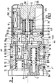
- la figure 2 est une vue en coupe axiale de l'actionneur électro-hydraulique selon l'invention ;
- la figure 3 est une vue selon la
flèche 3 de la figure 2, - la figure 4 est une vue partielle montrant la fixation du corps principal sur le corps d'interface de l'actionneur.
- Figure 1 is a schematic sectional view of the fluid control module comprising the electro-hydraulic actuator according to the invention;
- Figure 2 is an axial sectional view of the electro-hydraulic actuator according to the invention;
- FIG. 3 is a view according to
arrow 3 in FIG. 2, - FIG. 4 is a partial view showing the fixing of the main body to the interface body of the actuator.
L'actionneur électro-hydraulique selon l'invention se monte à l'intérieur d'un corps d'alimentation 241 pour la commande d'un embrayage, tel que décrit dans le susmentionné document EP-A-0 493 992 dont le contenu est considéré comme annexé à la présente invention. Par simplification les mêmes références seront reprises pour les éléments communs à la présente invention et à ceux du susmentionné document.The electro-hydraulic actuator according to the invention is mounted inside a supply body 241 for controlling a clutch, as described in the above-mentioned document EP-A-0 493 992, the content of which is considered to be annexed to the present invention. For simplification, the same references will be used for the elements common to the present invention and to those of the above-mentioned document.
Ainsi le corps 241 constitue un réceptacle 245 pour la réception du cylindre principal 135 à l'intérieur duquel coulisse le piston principal 136 portant la pièce de transfert 234. Ce corps constitue également un réceptacle cylindrique en-dessous du cylindre principal pour montage étanche de l'actionneur électro-hydraulique 352 selon l'invention ici par vissage.Thus the body 241 constitutes a receptacle 245 for the reception of the main cylinder 135 inside which slides the main piston 136 carrying the
Cet actionneur électro-hydraulique 352 comporte en succession axiale un corps principal 100, un corps d'interface 110 et un électro-aimant 120.This electro-
Cette disposition facilite la fabrication de l'actionneur et permet d'orienter les tiroirs 1,2,3, décrits ci-après, dans le sens longitudinal.This arrangement facilitates the manufacture of the actuator and makes it possible to orient the
A l'intérieur du corps principal sont montés longitudinalement un tiroir de régulation de pression 1 ou tiroir principal, et selon l'invention un tiroir réducteur de pression 2 ou tiroir secondaire. Les tiroirs 1 et 2 sont donc montés parallèlement l'un par rapport à l'autre et ici de part et d'autre de l'axe de symétrie longitudinal 50 de l'actionneur 352.Inside the main body are longitudinally mounted a pressure regulating
L'électro-aimant comporte, de manière connue en soi, une bobine 4 avec son support montée dans un corps en matériau ferromagnétique 41,43, tel que du fer doux, et un tiroir de découpage 3, centralement creux et monté centralement dans le corps 41,43 plus particulièrement dans un trou borgne 30 de celui-ci débouchant au niveau du corps 110. Le corps 41,43 est en deux parties, à savoir un noyau 41 dorsal et une carcasse 43 avant pour emprisonner axialement la bobine 4 et son support. Un joint d'étanchéité 44 est interposé entre la face dorsale de la carcasse 42 et la face avant du noyau 41. Le joint 44 est entouré par le support de la bobine 4.The electromagnet comprises, in a manner known per se, a coil 4 with its support mounted in a body made of
Le tiroir de découpage 3 est également en matériau ferromagnétique, ici du fer doux, et est soumis à l'action d'un ressort 31 prenant appui contre le fond du trou borgne 30 (la face avant du noyau 41) et contre un anneau de butée 32, tel qu'un circlips, monté à l'intérieur de l'alésage interne du tiroir 3. Le tiroir 3 est également soumis à l'action du champ magnétique crée par la bobine 4, l'action du champ magnétique étant antagoniste par rapport à celle du ressort 31.The
Le tiroir 3 est ainsi destiné à obturer un siège 37 ou à ouvrir celui-ci, ledit siège 37 étant formé à la faveur de la face dorsale du corps d'interface 110.The
Ainsi il est créé une électrovalve du type à battement, la bobine recevant, comme dans le susmentionné document EP-A-0 493 992, des informations du calculateur. Cette bobine 4 commute le tiroir de découpage 3 d'une position ouverte à une position fermée suivant le rapport cyclique.Thus, a flap type solenoid valve is created, the coil receiving, as in the aforementioned document EP-A-0 493 992, information from the computer. This coil 4 switches the
L'extrémité avant du tiroir 3 présente une gorge 33, tandis que son extrémité arrière porte un joint d'étanchéité 46 propre à coopérer avec la face avant du noyau 41.The front end of the
L'électro-aimant 120 est entouré par une bague 34 dont les extrémités sont rabattues au contact avec la face dorsale du noyau 41 et avec le corps d'interface 110, doté à sa périphérie externe d'une gorge 111 à section en forme de V à cet effet. Ainsi l'électro-aimant 12 est rapporté par sertissage sur le corps d'interface 110. Ce corps d'interface 110 est fixé par vissage sur le corps principal 100. Comme visible à la figure 2, le noyau 41 et la carcasse 43 sont creusés pour délimiter avec la bague 34 une cavité annulaire de logement de la bobine 4 avec son support.The
Le corps principal 100 est doté de deux perçages traversants longitudinaux 10,20 pour respectivement montage du tiroir principal 1 et du tiroir 2, qui ainsi, suivant une caractéristique de l'invention, sont montés dans le sens longitudinal parallèlement par rapport au tiroir de découpage 3. Les perçages 10 et 20 s'étendent globalement symétriquement par rapport à l'axe 50, de part et d'autre de celui-ci.The
Le tiroir de régulation de pression 1 est doté centralement d'un trou borgne 13 pour logement d'un ressort hélicoïdal 11 à l'intérieur dudit trou 13. Ce ressort prend appui sur le fond du trou borgne 13 et sur un piston obturateur 5, formant capuchon, monté également dans le perçage 10. Le piston 5 est dirigé vers la face avant du corps principal 100. Le tiroir 1 permet donc de réguler la pression d'utilisation.The
Le tiroir réducteur de pression 2 est soumis à l'action d'un ressort 21 prenant appui sur la face avant du tiroir 2 en étant monté dans le perçage 20. Ainsi les ressorts 11 et 21 sollicitent les tiroirs 1,2 en direction du corps d'interface 110 et donc de la face dorsale du corps 100.The
La périphérie externe du tiroir 1 présente une gorge 14 propre à venir découvrir ou refermer une gorge 70 en communication, de manière décrite ci-après, par un canal transversal 71 débouchant dans une gorge périphérique 72 du corps 100, avec l'utilisation (ici avec la canalisation 204) c'est-à-dire avec la chambre de commande 173 délimitée par le cylindre principal 135. La gorge 70 est formée à la faveur du perçage 10.The outer periphery of the
On voit en 80 une gorge d'arrivée de pression en communication avec la gorge périphérique 14 du tiroir 1. Cette gorge 80, reliée à la source de pression de manière décrite ci-après, telle celle destinée à la direction assistée ou en variante une centrale spécifique, est en communication avec le tiroir 2, le corps 100 étant percé transversalement de part en part à cet effet pour formation d'un canal 81.80 shows a pressure inlet groove in communication with the peripheral groove 14 of the
Plus précisément, le canal 71 est en communication avec un perçage longitudinal 95 débouchant au niveau de la face avant du corps principal 100.More specifically, the
De même, le canal 81 est en communication avec un perçage longitudinal 94 débouchant au niveau de la face avant du corps principal 100.Likewise, the
Les perçages 94,95 sont disposés symétriquement de part et d'autre de l'axe de symétrie passant par le centre des perçages 10,20 (figure 3).The holes 94.95 are arranged symmetrically on either side of the axis of symmetry passing through the center of the holes 10.20 (Figure 3).
Le perçage 95 est en communication avec la canalisation 204 d'alimentation de la chambre de commande 173, tandis que le perçage 94 est en communication avec la canalisation d'arrivée 202 du corps 241.The
Les canaux 71,81 et les gorges 72,80 sont décalées axialement et trois joints d'étanchéité sont prévus (figure 2) pour étancher les gorges 72,80.The
Les canaux 71,81 débouchent à chacune de leurs extrémités respectivement dans les gorges 72,80.The
Le canal 71 intercepte les perçages 10,95, tandis que le canal 81 intercepte les perçages 10,94.
Ainsi qu'on l'aura compris, on peut alimenter l'utilisation à partir des gorges 72,80 ou des perçages 94,95, et c'est la raison pour laquelle à la figure 2 les flèches ont été associées aux gorges 72,80.As we will have understood, we can feed the use from the grooves 72.80 or the holes 94.95, and this is the reason why in FIG. 2 the arrows have been associated with the
Ainsi l'actionneur électro-hydraulique présente un corps 100,110,120 avec une entrée ou arrivée d'alimentation 81,80-94 et une sortie d'utilisation 71,72-95. Ici on utilise les perçages 94,95, le corps 100 cooperant à étanchéité avec l'alésage interne 244 du réceptacle 244 de la valve 352. Ainsi, grâce aux joints de la figure 2 et au réceptacle 244 les gorges 71,80 sont fermés.Thus the electro-hydraulic actuator has a body 100,110,120 with a supply inlet or
De manière connue en soi, le tiroir 2 est doté intérieurement d'un alésage 25 en forme de T. L'alésage 25 du tiroir 2 est en communication axialement avec le corps d'interface 110 et transversalement avec le canal 81 qu'il recouvre plus ou moins avec formation d'une restriction portant la référence 8 à la figure 2.In a manner known per se, the
Plus précisément, le tiroir 2 est propre à venir en butée contre un joint 90 interposé axialement entre la face dorsale du corps 100 et la face avant du corps d'interface 110.More specifically, the
Ce joint 90 est percé pour permettre la circulation du fluide de manière décrite ci-après.This
De même le tiroir 1 présente intérieurement un alésage, globalement en forme de T, formé par le trou borgne 13 d'orientation longitudinale et par un canal perpendiculaire portant la référence 15. L'alésage en forme de T est fermé par le piston 5.Likewise, the
Le canal 15 communique avec la gorge 70 et le canal 71.The channel 15 communicates with the
Le tiroir 1 recouvre également plus ou moins la gorge 70 avec formation de restrictions portant les références 7,7' à la figure 2. La restriction 7 intervient au niveau des gorges 14,70, tandis que la restriction 7' intervient entre la gorge 70 et une rainure 63 décrite ci-après. Cette rainure 63 permet un retour au réservoir et est en communication avec la canalisation de retour au reservoir 212 grâce à la gorge 184 formée à l'arrière du réceptacle 244.The
On notera que la gorge 14 cylindrique a en section un fond plat et des flancs inclinés pour une bonne progressivité lors du recouvrement et du découvrement de la gorge 70 par le tiroir.It will be noted that the cylindrical groove 14 has in section a flat bottom and inclined sides for good progressiveness during the covering and the uncovering of the
Ainsi le tiroir 1, soumis intérieurement à la pression de l'utilisation, permet de réguler la pression dans le canal d'utilisation 204 et donc de réguler la pression d'utilisation grâce aux restrictions 7,7'.Thus the
Une chambre de pilotage 16 est formée entre le tiroir 1 et le corps d'interface 110. De même une chambre de réduction 26 est formée entre le tiroir 2 et le corps d'interface 110. Ces chambres sont délimitées par le joint 90.A pilot chamber 16 is formed between the
Ainsi qu'on l'aura compris, de manière connue en soi, le mouvement des tiroirs 1 et 2 est déterminé par la pression régnant respectivement dans les chambres 16 et 26, ainsi que par l'action antagoniste des ressorts, ici du type à boudin, respectivement 11,21 et que par la pression d'utilisation agissant sur le piston antagoniste 5.As will be understood, in a manner known per se, the movement of the
On notera que la pression d'utilisation agit sur une surface moindre que la face d'extrémité du tiroir 1 délimitant la chambre 16. Ainsi la pression dans la chambre 16 peut être réduite par rapport à la pression d'utilisation régnant dans le trou 13.It will be noted that the working pressure acts on a smaller surface than the end face of the
Un canal tortueux 93 est percé dans le corps d'interface 110 et le joint 90 pour relier la chambre 16 à une gorge ou chambre de découpage 36 formée dans le corps 41,43 (la face avant de la carcasse 43) via le tiroir 3. La gorge 36 cylindrique a en section un fond plat et des flancs inclinés. L'un des flancs inclinés permet une communication de la chambre 36 avec le tiroir 3. Cette chambre 36 est recouverte par le corps 110.A
On notera la présence d'un joint d'étanchéité torique (figure) entre le corps 110, la carcasse 43 et la bague 34 pour éviter toute fuite. Le tiroir 3 est ainsi apte à obturer ou à ouvrir la chambre 36. De même, un perçage longitudinal 92 est formé dans le corps 110 et le joint 90 et permet une communication entre le tiroir de découpage 3 et la chambre de réduction 26 via la chambre 36.Note the presence of an O-ring seal (figure) between the
Cette chambre 36 entoure extérieurement le tiroir 3, dont l'alésage interne forme une chambre de réserve.This
Le dispositif fonctionne de la manière suivante : la pression d'alimentation arrive dans la gorge 80 par le perçage 94 et le canal 81, puis pénètre dans la gorge périphérique 14 du tiroir 1, qui est ainsi admis à se déplacer dans un sens ou dans l'autre à l'encontre de la force exercée par le ressort 11 et par le piston antagoniste 5. Ce tiroir découvre ainsi plus ou moins la gorge 70, ce qui permet de moduler la pression d'alimentation de l'utilisation (pression dans la chambre 173), grâce aux restrictions 7,7'.The device operates as follows: the supply pressure arrives in the
Corollairement le fluide, par le canal 81 et la restriction 8, entre en communication avec le perçage en T 25 du tiroir 2, qui est admis ainsi à se déplacer dans un sens ou dans l'autre, à l'encontre de l'action exercée par le ressort 21, puis le fluide transite du canal 25 à la chambre 26, puis à travers le perçage 92, formant canal, et parvient dans la gorge 36.As a corollary, the fluid, through the
Le tiroir 3, qui présente à ses extrémités avant et arrière respectivement une gorge 33 et une gorge 46, est apte à obturer ou découvrir plus ou moins le siège 37 formé en regard dans le corps 110, et à interrompre ainsi une communication entre la chambre 36 et la chambre 16 via le canal 93, qui débouche dans l'alésage central du tiroir 3. Grâce aux gorges 33 et 46 du tiroir 3, il est formé des chambres d'équilibrage évitant tout contact brutal de fin de course du tiroir 3 sur le corps 110 et la carcasse 43. La communication, entre la gorge 36 et le canal 93, est ainsi plus ou moins interrompue, en sorte que la pression dans la chambre de pilotage 16 est variable en étant plus ou moins haute.The
Ainsi qu'on l'aura compris, le tiroir réducteur de pression permet d'abaisser la pression d'alimentation qui parvient dans la chambre 36. Par exemple si la pression d'alimentation variable est de l'ordre de 20 à 40 bars, la pression dans la chambre 26 sera de l'ordre de 5 bars, la pression dans la chambre de pilotage 16 variant ainsi de 0 à 5 bars.As will be understood, the pressure reducing drawer makes it possible to lower the supply pressure which reaches the
Grâce aux restrictions 7,7' le déplacement du tiroir 1 permet de réduire la pression d'utilisation en pratique de 0 à 20 bars.Thanks to the restrictions 7,7 ', the movement of the
Ainsi la pression dans la chambre de pilotage 16 dépend du mouvement du tiroir de découpage 3 et donc des signaux envoyés par le calculateur à la bobine 4.Thus the pressure in the control chamber 16 depends on the movement of the
Le tiroir 3 de l'électro-aimant 120 pilote donc le tiroir de régulation 1 ou tiroir principal.The
Bien entendu, il est prévu dans le corps 100 un canal 60 de retour à la bâche ou réservoir (canalisation 212) avec un gicleur 61 pour communication de la chambre 16 avec la bâche. Le canal 60 débouche dans la rainure 63 en communication avec la gorge 184.Of course, there is provided in the body 100 a
Ainsi la pression dans la chambre 16 dépend du gicleur 61 et lorsque le tiroir 3 est en contact avec son siège 37, la pression dans la chambre 16 chute progressivement à cause du gicleur 61.Thus the pressure in the chamber 16 depends on the
Suivant une autre caractéristique, la face avant du corps 100 est dotée d'une rainure transversale 63 en forme de queue d'aronde. Cette rainure (figure 3) permet une communication avec la canalisation 212 de manière précitée et également le montage d'un cavalier 64, de forme complémentaire, servant d'appui au piston 5 et au ressort 21. Ainsi les tiroirs 1 et 2 ne peuvent s'échapper et ne risquent pas d'être déformés lors du montage de l'électrovalve 352 dans son réceptacle (figure 1).According to another characteristic, the front face of the
Bien entendu, la présente invention n'est pas limitée à l'exemple de réalisation décrit. En particulier l'arrivée d'alimentation et la sortie d'utilisation peuvent être réalisées à la faveur des gorges 70,80.Of course, the present invention is not limited to the embodiment described. In particular, the supply inlet and the outlet for use can be carried out using the grooves 70.80.
On notera que la fixation du corps principal 100 avec le corps d'interface 110 est réalisée à l'aide de vis 500 montées dans les perçages 94,95 d'intervention de joints d'étanchéité 501 comme visible à la figure 4.It will be noted that the fixing of the
On appréciera d'une manière générale que l'électrovalve a des bons temps de réponse, que les frottements sont réduits ainsi que la consommation de courant, le tiroir 3 étant aisément déplaçable du fait qu'il est chargé faiblement par le ressort 31 et du fait du tiroir de réduction de pression 2 caractéristique de l'invention avec la chambre de pilotage 16.It will generally be appreciated that the solenoid valve has good response times, that the friction is reduced as well as the current consumption, the
L'électrovalve est également très compacte radialement et son montage se fait aisément par enfilage, tous les tiroirs 1 à 3, de forme cylindrique, s'étendant longitudinalement.The solenoid valve is also very compact radially and its assembly is easily done by threading, all the
Bien entendu l'actionneur peut commander non pas un embrayage comme dans la figure 1, mais la manoeuvre d'une boîte de vitesses ou autres.Of course the actuator can control not a clutch as in Figure 1, but the operation of a gearbox or the like.
Ainsi qu'il ressort à l'évidence de la déscription et des dessins le joints d'étanchéité 44 assure à la fois une rupture du chemin magnétique (le champs magnétique passant par la bague 34 avantageusement en matériau ferromagnétique), et une étanchéité du fluide vers les parties séches de la bobine 4.As is evident from the description and the drawings, the
Ce joint 44 permet également un contrôle aisé du jeu de battement du tiroir 3.This
En effet, lors de la fixation des corps 41,43 et 110 par sertissage à l'aide de la bague 34, il suffit d'introduire une butée épaulée dans le canal 93, qui, après traversée du ressorts 31 est propre à servir de butée au noyau 41.Indeed, during the fixing of the
Une côte précise est ainsi définie entre la tête de la butée, propre à venir en contact avec la face avant du corps 110, et le pied de la butée, propre à venir en contact avec la face avant du noyau 41.A precise rib is thus defined between the head of the stop, suitable for coming into contact with the front face of the
On notera qu'ainsi un entrefer 46 déterminé existe entre l'extrémité arrière du tiroir 3 et la face avant du noyau 41.It will be noted that thus a
Le champs magnétique est déterminé par cet entrefer, et se referme à travers les pièces 41,3,42.The magnetic field is determined by this air gap, and closes through the
On notera que le joint 90 d'étanchéité fait également office de butée par les tiroirs 1,2 en sorte que les bruits sont réduits. Ce joint obture également la partie horizontale du passage 93 coaxiale au tiroir 3. Ce joint est percé pour communication du passage 93 avec la chambre 16.It will be noted that the
Le tiroir 3 contrôle par son battement (déplacement axial) la pression venant de la chambre 36 vers la gorge antichoc 33, puis vers la chambre 16, ce qui permet d'augmenter les débits contrôlés pour une même force magnétique.The
Le tiroir 3 est équilibré vis-à-vis des pressions hydrauliques et est donc soumis à l'action du champs magnétique se refermant par l'entrefer 46 et également le ressorts antagoniste 31.The
Le tiroir 1 est en équilibre sous l'effet de la pression de pilotage régnant dans la chambre 16, le ressorts antagoniste de fermeture 11 la pression antagoniste régnant dans la chambre 13. Les sections internes (trou 13) et externe du piston sont donc fonction des applications.The
On appréciéra que le guidage du tiroir 1 est augmenté par l'intermédiare du perçage au alésage 10 se prolongeant dans la rainure 62.It will be appreciated that the guide of the
On notera également que l'usinage du corps principal est aisé grâce aux perçages 94,95, aux canaux 71,72, aux gorges 70,72,80 et à la rainure 63. Ce corps 100 est d'un emploi universel, l'entrée et la sortie du fluide pouvant se faire de deux manières différentes, et c'est la raison pour laquelle on a prévu des joints (figure 1) pour rendre étanche l'entrée des perçages 94 et 95 au niveau du fond du réceptacle 244 et de l'entrée des conduites menant respectivement à l'entrée 202 et à la chambre 204.It will also be noted that the machining of the main body is easy thanks to the holes 94.95, the channels 71.72, the grooves 70.72.80 and the
On notera qu'une plaque de fixation 400 fixée par vissage dans le corps 241 (figure 1) permet de plaquer le corps principal 100 contre le fond de l'alésage 244 et de comprimer les joints précités associés aux percages au conduites 94,95. La coopération de la plaque 400 avec le corps 100 permet de réduire la chaîne des côtés.It will be noted that a fixing
Cette plaque 400 centre le corps 110 et présente un alésage centrale conformé pour créer un détrompeur en coopération avec la surface externe du corps 110, afin de monter la valve 352 dans la bonne position.This
Bien entendu on peut fixer autrement entre eux les corps 100 et 110, par exemple par vissage en dehors des perçages 94,95 alors de forme borgne. On peut faire appel à des tirants pour fixer le corps 110 aux corps 44,43.Of course, the
Claims (10)
Applications Claiming Priority (2)
| Application Number | Priority Date | Filing Date | Title |
|---|---|---|---|
| FR9207819A FR2692942B1 (en) | 1992-06-25 | 1992-06-25 | ELECTRO-HYDRAULIC ACTUATOR, IN PARTICULAR FOR THE CONTROL OF A CLUTCH OF A MOTOR VEHICLE. |
| FR9207819 | 1992-06-25 |
Publications (2)
| Publication Number | Publication Date |
|---|---|
| EP0577482A1 true EP0577482A1 (en) | 1994-01-05 |
| EP0577482B1 EP0577482B1 (en) | 1996-03-13 |
Family
ID=9431190
Family Applications (1)
| Application Number | Title | Priority Date | Filing Date |
|---|---|---|---|
| EP93401640A Expired - Lifetime EP0577482B1 (en) | 1992-06-25 | 1993-06-25 | Electrohydraulic actuator especially for controlling a motor vehicle clutch |
Country Status (4)
| Country | Link |
|---|---|
| EP (1) | EP0577482B1 (en) |
| DE (1) | DE69301782T2 (en) |
| ES (1) | ES2086202T3 (en) |
| FR (1) | FR2692942B1 (en) |
Families Citing this family (1)
| Publication number | Priority date | Publication date | Assignee | Title |
|---|---|---|---|---|
| JP2001343032A (en) * | 2000-06-01 | 2001-12-14 | Komatsu Ltd | Fluid pressure control valve of clutch or brake and fluid pressure control method |
Citations (5)
| Publication number | Priority date | Publication date | Assignee | Title |
|---|---|---|---|---|
| GB1097869A (en) * | 1965-08-30 | 1968-01-03 | Ford Motor Co | Friction clutch control system |
| US4513850A (en) * | 1983-02-09 | 1985-04-30 | Allis-Chalmers Corporation | Electrohydraulic power shift transmission system |
| US4836057A (en) * | 1985-02-19 | 1989-06-06 | Kabushiki Kaisha Komatsu Seisakusho | Method of controlling speed change clutches in a transmission |
| US5035312A (en) * | 1987-03-25 | 1991-07-30 | Kabushiki Kaisha Komatsu Seisakusho | Apparatus for controlling hydraulic pressure for clutch |
| EP0493992A1 (en) * | 1990-12-07 | 1992-07-08 | Valeo | Control actuator of a friction clutch with a diaphragm, especially for a motor vehicle |
-
1992
- 1992-06-25 FR FR9207819A patent/FR2692942B1/en not_active Expired - Fee Related
-
1993
- 1993-06-25 EP EP93401640A patent/EP0577482B1/en not_active Expired - Lifetime
- 1993-06-25 ES ES93401640T patent/ES2086202T3/en not_active Expired - Lifetime
- 1993-06-25 DE DE69301782T patent/DE69301782T2/en not_active Expired - Fee Related
Patent Citations (5)
| Publication number | Priority date | Publication date | Assignee | Title |
|---|---|---|---|---|
| GB1097869A (en) * | 1965-08-30 | 1968-01-03 | Ford Motor Co | Friction clutch control system |
| US4513850A (en) * | 1983-02-09 | 1985-04-30 | Allis-Chalmers Corporation | Electrohydraulic power shift transmission system |
| US4836057A (en) * | 1985-02-19 | 1989-06-06 | Kabushiki Kaisha Komatsu Seisakusho | Method of controlling speed change clutches in a transmission |
| US5035312A (en) * | 1987-03-25 | 1991-07-30 | Kabushiki Kaisha Komatsu Seisakusho | Apparatus for controlling hydraulic pressure for clutch |
| EP0493992A1 (en) * | 1990-12-07 | 1992-07-08 | Valeo | Control actuator of a friction clutch with a diaphragm, especially for a motor vehicle |
Also Published As
| Publication number | Publication date |
|---|---|
| FR2692942B1 (en) | 1995-07-28 |
| ES2086202T3 (en) | 1996-06-16 |
| FR2692942A1 (en) | 1993-12-31 |
| EP0577482B1 (en) | 1996-03-13 |
| DE69301782D1 (en) | 1996-04-18 |
| DE69301782T2 (en) | 1996-09-19 |
Similar Documents
| Publication | Publication Date | Title |
|---|---|---|
| US7621386B2 (en) | Viscous fan drive having modified land design and armature venting | |
| EP0016436B1 (en) | Servo valve | |
| FR2935771A1 (en) | DEVICE FOR CONTROLLING THE SUPPLY OF A SYSTEM WITH A FLUID | |
| EP0493992B1 (en) | Control actuator of a friction clutch with a diaphragm, especially for a motor vehicle | |
| EP0194927B1 (en) | Pressure control servo device for a hydraulic installation, particularly for vehicle servo steering | |
| FR2703730A1 (en) | Improvements to liquid cooling circuits for internal combustion engines. | |
| EP1643139B1 (en) | Exchange valve device | |
| CA1162130A (en) | Hydrodynamic torque converter with bridging means | |
| EP0577482B1 (en) | Electrohydraulic actuator especially for controlling a motor vehicle clutch | |
| EP0173625B1 (en) | Fluid pressure-actuated device with wear compensation, especially for friction clutch mechanisms | |
| FR2764649A1 (en) | FUEL METERING VALVE FOR A FUEL INJECTION SYSTEM OF AN INTERNAL COMBUSTION ENGINE | |
| EP1486843B1 (en) | Thermostatic valve for a fluid circulation circuit and internal combustion engine provided with a fluid circulation circuit comprising such a valve | |
| EP0072732B1 (en) | A fluid flow regulator for a servosteering installation | |
| EP0306368B1 (en) | Pressure compensator valve for a hydraulic proportional directional valve, and hydraulic directional valve comprising it | |
| FR2461826A1 (en) | FUEL INJECTION PUMP FOR INTERNAL COMBUSTION ENGINES | |
| FR2578919A1 (en) | CONTROLLED FLOW CONTROL DEVICE FOR HYDRAULIC SYSTEM, PARTICULARLY FOR POWER STEERING OF VEHICLE | |
| EP3163076A1 (en) | Hydraulic machine with two displacements and safety valve | |
| EP3098456B1 (en) | Servovale with pilot stage of the jet type | |
| EP0202154B1 (en) | Flow control servo device for a hydraulic installation, particularly for servo steering an automotive vehicle | |
| FR2749544A1 (en) | IMPROVED DEVICE FOR HYDRAULICALLY CONTROLLING A CLUTCH OF A MOTOR VEHICLE | |
| EP0117207A1 (en) | Hydraulic distribution device | |
| FR2892486A1 (en) | VALVE WITH AMORTIE OPENING | |
| EP1375951A1 (en) | Clutch control system | |
| FR2566492A1 (en) | Device for actuating a friction clutch. | |
| EP0290700A1 (en) | Modulation unit for fluid under pressure, particularly for a servo steering of a vehicle |
Legal Events
| Date | Code | Title | Description |
|---|---|---|---|
| PUAI | Public reference made under article 153(3) epc to a published international application that has entered the european phase |
Free format text: ORIGINAL CODE: 0009012 |
|
| AK | Designated contracting states |
Kind code of ref document: A1 Designated state(s): DE ES FR GB IT |
|
| 17P | Request for examination filed |
Effective date: 19940528 |
|
| 17Q | First examination report despatched |
Effective date: 19950125 |
|
| GRAH | Despatch of communication of intention to grant a patent |
Free format text: ORIGINAL CODE: EPIDOS IGRA |
|
| GRAA | (expected) grant |
Free format text: ORIGINAL CODE: 0009210 |
|
| AK | Designated contracting states |
Kind code of ref document: B1 Designated state(s): DE ES FR GB IT |
|
| REF | Corresponds to: |
Ref document number: 69301782 Country of ref document: DE Date of ref document: 19960418 |
|
| ITF | It: translation for a ep patent filed | ||
| REG | Reference to a national code |
Ref country code: ES Ref legal event code: FG2A Ref document number: 2086202 Country of ref document: ES Kind code of ref document: T3 |
|
| GBT | Gb: translation of ep patent filed (gb section 77(6)(a)/1977) |
Effective date: 19960618 |
|
| PLBE | No opposition filed within time limit |
Free format text: ORIGINAL CODE: 0009261 |
|
| STAA | Information on the status of an ep patent application or granted ep patent |
Free format text: STATUS: NO OPPOSITION FILED WITHIN TIME LIMIT |
|
| 26N | No opposition filed | ||
| REG | Reference to a national code |
Ref country code: GB Ref legal event code: IF02 |
|
| REG | Reference to a national code |
Ref country code: FR Ref legal event code: TP |
|
| PGFP | Annual fee paid to national office [announced via postgrant information from national office to epo] |
Ref country code: GB Payment date: 20060606 Year of fee payment: 14 |
|
| PGFP | Annual fee paid to national office [announced via postgrant information from national office to epo] |
Ref country code: ES Payment date: 20060616 Year of fee payment: 14 |
|
| PGFP | Annual fee paid to national office [announced via postgrant information from national office to epo] |
Ref country code: DE Payment date: 20070612 Year of fee payment: 15 |
|
| PGFP | Annual fee paid to national office [announced via postgrant information from national office to epo] |
Ref country code: IT Payment date: 20070616 Year of fee payment: 15 |
|
| GBPC | Gb: european patent ceased through non-payment of renewal fee |
Effective date: 20070625 |
|
| PGFP | Annual fee paid to national office [announced via postgrant information from national office to epo] |
Ref country code: FR Payment date: 20070629 Year of fee payment: 15 |
|
| PG25 | Lapsed in a contracting state [announced via postgrant information from national office to epo] |
Ref country code: GB Free format text: LAPSE BECAUSE OF NON-PAYMENT OF DUE FEES Effective date: 20070625 |
|
| REG | Reference to a national code |
Ref country code: ES Ref legal event code: FD2A Effective date: 20070626 |
|
| PG25 | Lapsed in a contracting state [announced via postgrant information from national office to epo] |
Ref country code: ES Free format text: LAPSE BECAUSE OF NON-PAYMENT OF DUE FEES Effective date: 20070626 |
|
| REG | Reference to a national code |
Ref country code: FR Ref legal event code: ST Effective date: 20090228 |
|
| PG25 | Lapsed in a contracting state [announced via postgrant information from national office to epo] |
Ref country code: DE Free format text: LAPSE BECAUSE OF NON-PAYMENT OF DUE FEES Effective date: 20090101 |
|
| PG25 | Lapsed in a contracting state [announced via postgrant information from national office to epo] |
Ref country code: IT Free format text: LAPSE BECAUSE OF NON-PAYMENT OF DUE FEES Effective date: 20080625 Ref country code: FR Free format text: LAPSE BECAUSE OF NON-PAYMENT OF DUE FEES Effective date: 20080630 |