EP0577049A1 - Photographic film cassette, camera for use therewith and method of manufacturing the cassette - Google Patents
Photographic film cassette, camera for use therewith and method of manufacturing the cassette Download PDFInfo
- Publication number
- EP0577049A1 EP0577049A1 EP93110295A EP93110295A EP0577049A1 EP 0577049 A1 EP0577049 A1 EP 0577049A1 EP 93110295 A EP93110295 A EP 93110295A EP 93110295 A EP93110295 A EP 93110295A EP 0577049 A1 EP0577049 A1 EP 0577049A1
- Authority
- EP
- European Patent Office
- Prior art keywords
- photographic film
- cassette
- projections
- pair
- passageway
- Prior art date
- Legal status (The legal status is an assumption and is not a legal conclusion. Google has not performed a legal analysis and makes no representation as to the accuracy of the status listed.)
- Granted
Links
Images


Classifications
-
- G—PHYSICS
- G03—PHOTOGRAPHY; CINEMATOGRAPHY; ANALOGOUS TECHNIQUES USING WAVES OTHER THAN OPTICAL WAVES; ELECTROGRAPHY; HOLOGRAPHY
- G03B—APPARATUS OR ARRANGEMENTS FOR TAKING PHOTOGRAPHS OR FOR PROJECTING OR VIEWING THEM; APPARATUS OR ARRANGEMENTS EMPLOYING ANALOGOUS TECHNIQUES USING WAVES OTHER THAN OPTICAL WAVES; ACCESSORIES THEREFOR
- G03B17/00—Details of cameras or camera bodies; Accessories therefor
- G03B17/28—Locating light-sensitive material within camera
- G03B17/30—Locating spools or other rotatable holders of coiled film
-
- G—PHYSICS
- G03—PHOTOGRAPHY; CINEMATOGRAPHY; ANALOGOUS TECHNIQUES USING WAVES OTHER THAN OPTICAL WAVES; ELECTROGRAPHY; HOLOGRAPHY
- G03B—APPARATUS OR ARRANGEMENTS FOR TAKING PHOTOGRAPHS OR FOR PROJECTING OR VIEWING THEM; APPARATUS OR ARRANGEMENTS EMPLOYING ANALOGOUS TECHNIQUES USING WAVES OTHER THAN OPTICAL WAVES; ACCESSORIES THEREFOR
- G03B2217/00—Details of cameras or camera bodies; Accessories therefor
- G03B2217/26—Holders for containing light-sensitive material and adapted to be inserted within the camera
- G03B2217/261—Details of spools
Abstract
Description
- The present invention relates to a photographic film cassette, a camera for use therewith, and a method of manufacturing the cassette. More particularly, the present invention relates to an improvement of a photographic film cassette in which a leader of a photographic film can be advanced to the outside of a cassette shell when a spool is rotated in an unwinding direction, and a camera and a manufacture method relevant to such a cassette.
- A known photographic film cassette includes a photographic film positioned so that a leader does not protrude from the cassette shell prior to loading a camera with it. Such a cassette is loaded into a camera favorably with great ease. A simple photographic film-transporting mechanism of the camera is typically used with this type of cassette, and includes a construction which rotates a spool to unwind a photographic film strip (hereinafter called as film), thereby causing the leader to move through a passageway for the photographic film and exit from the cassette, as suggested in USP 4,834,306 and USP 5,174,519. To prevent ambient light from entering the cassette shell, plush or light-trapping ribbons are conventionally attached to the inside of the passageway. It is also disclosed in USP 4,221,479 that a movable closing structure openably and light-tightly encloses the inside of the cassette shell.
- The closing structure, when loading a camera with the cassette, is opened by a camera, before the advancing mechanism incorporated in the camera rotates the spool in the unwinding direction so as to advance the leader. The closing structure is closed when the photographic film is wound back into the cassette shell after the exposure of the photographic film is completed, and protects the exposed photographic film inside from being subjected to ambient light inadvertently. Substitution of the closing structure for plush during advancement of the photographic film is favorable, because less load is applied to the leader in use of the closing structure than by plush, so as to facilitate the advancement of the leader in rotating the spool.
- It is well known that the photographic film is constituted by applying photosensitive emulsion to one surface of a support, which is formed e.g. of cellulose triacetate (TAC). In the manufacturing process, the photographic film is dried after applying the coating of emulsion to the support. The photographic film is shrunk while dried, to degrees different between the emulsion surface and the back surface. As illustrated in Fig. 25, an
emulsion surface 2a is shrunk more than aback surface 2b, so as to make aphotographic film 2 curl and make convex at theback surface 2b like an archway, or eaves trough. When aspool 40a is rotated, aleader 2d of thephotographic film 2 is exited through apassage mouth 5 from acassette shell 40b, with an arch-curled amount of W. - The photographic film cassette in Fig. 25 incorporates a
shutter member 194 as closing structure openable at thepassage mouth 5, which lacks plush. The bothsurfaces photographic film 2 come in direct contact with walls inside thepassage mouth 5. The curling of thephotographic film 2 like an archway causes the inside of thecassette shell 40b to rub thephotographic film 2, in particular theback surface 2b, until thecassette shell 40b scratches thephotographic film 2. In printing picture frames on thephotographic film 2 as exposed, such scratches on thephotographic film 2 would be conspicuously enlarged on photoprints as obtained, so as to lower the quality of the photoprints. - In view of the foregoing problems, an object of the present invention is to provide a photographic film cassette, a camera for use therewith, and a method of manufacturing the cassette, in which scratches unfavorable to the image quality of photographic film can be avoided.
- Another object of the present invention is to provide a photographic film cassette, a camera for use therewith, and a method of manufacturing the cassette, in which a movable closing structure, openably and light-tightly enclosing the inside of the cassette shell, can be formed with great ease.
- In order to achieve the above and other objects and advantages of this invention, a passageway is formed communicatively between the passage mouth and the roll chamber for passing the photographic film, and is formed between opposite first and second inside faces as spaced. The first inside face faces on the emulsion surface of the photographic film. The second inside face faces on the back surface of the photographic film. A first pair of projections are formed on the first inside face for coming in contact with the emulsion surface in an outside of exposure-designated areas relative to a width of the photographic film. A second pair of projections are formed on the second inside face for coming in contact with the back surface in an outside of exposure-designated areas relative to the width of the photographic film, so as to regulate tendency of the photographic film to curl relative to the width in cooperation with the first pair of projections.
- According to the present invention, scratches unfavorable to the image quality of photographic film can be avoided. Light can be shielded at the passageway, without use of plush or light-trapping ribbons.
- Further, a shutter rod is arranged in the passageway for preventing ambient light from entering the roll chamber, and is rotatably supported between the first and second shell halves to be displaceable between closed and open positions in the passageway. A slot is formed through the shutter rod and has first and second opposite walls. When the shutter rod stands in the closed position, the walls block the passageway so as to shield ambient light. When the shutter rod stands in the open position, the slot is aligned with the passageway so as to allow the photographic film to pass. To produce the photographic film cassette, a first single mold is used for forming the first wall of the slot having the first pair of projections.
- The shutter member thus constructed can be formed with great ease, because no movable part, called a slide core, is required in molding the shutter member to be movable in the molds, in addition to the molds respectively for the core side and the cavity side, for the purpose of forming the projections in the slot.
- A camera for use with the cassette comprises a cassette chamber for containing the cassette shell. Rotating means is arranged in the cassette chamber for rotating the spool, which is rotated in the unwinding direction so as to exit the leader of the photographic film through the passage mouth. A receiving gate is formed with the cassette chamber for receiving the photographic film exited from the passage mouth with the cassette shell loaded, and has front and rear walls. A third pair of projections are formed on the front wall for coming in contact with the photographic film in an outside of exposure-designated areas relative to the width of the photographic film. A fourth pair of projections are formed on the rear wall for coming in contact with the photographic film in an outside of exposure-designated areas relative to the width of the photographic film, in positions inward from the third pair of projections relative to the width, so as to regulate tendency of the photographic film to curl relative to the width in cooperation with the third pair of projections.
- To prevent the photographic film from damage in a different manner from the present invention, it would be conceived to widen the range of a passageway in the direction of the thickness of the photographic film. However, this would be impractical and unfavorable, because it would enlarge the size of the photographic film cassette, and be inconsistent with cameras which demands an exit of the photographic film from the cassette while well positioned for being received in the camera. However, the novel cassette or camera according to the present invention avoids scratches without enlarging the size of the photographic film cassette. This is also favorable in well positioning the photographic film for being received in the camera.
- The above objects and advantages of the present invention will become more apparent from the following detailed description when read in connection with the accompanying drawings, in which:
- Fig. 1 is an exploded perspective view illustrating a photographic film cassette according to the present invention;
- Fig. 2 is a cross section illustrating the cassette in which a shutter plate is closed;
- Fig. 3 is a cross section illustrating the cassette in which the shutter plate is opened;
- Fig. 4 is a plan view illustrating a passage mouth with the shutter plate open;
- Fig. 5 is a plan view illustrating a passage mouth with photographic film exited through it;
- Fig. 6 is a partial view in cross section illustrating the cassette with the photographic film exited;
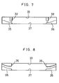
- Figs. 7 and 8 are explanatory views in plan view illustrating other preferred embodiments;
- Fig. 9 is an exploded perspective view illustrating a photographic film cassette having a movable shutter rod;
- Fig. 10 is a perspective view illustrating the shutter rod;
- Fig. 11 is a cross section illustrating the cassette in which a shutter rod is closed;
- Fig. 12 is a cross section illustrating the cassette in which the shutter rod is opened;
- Fig. 13 is a plan view illustrating a passage mouth with photographic film exited through it;
- Fig. 14 is a perspective view illustrating another preferred shutter rod;
- Fig. 15 is an explanatory view illustrating the cassette in Figs. 9 to 13, standing loaded in a suitable camera;
- Fig. 16 is an explanatory view illustrating the cassette with the shutter rod in Fig. 14, standing loaded in a suitable camera;
- Fig. 17 is a cross section illustrating the shutter rod in Figs. 9 to 13 while molded with a pair of molds, as viewed on Line XVII-XVII in Fig. 10;
- Fig. 18 is a cross section illustrating the shutter rod in Figs. 9 to 13 while molded with the molds, as viewed on Line XVIII-XVIII in Fig. 10;
- Fig. 19 is an explanatory view in exploded perspective illustrating the cavity-side mold;
- Fig. 20 is an explanatory view in exploded perspective illustrating the core-side mold;
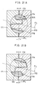
- Fig. 21A and 21B are cross sections illustrating a shutter rod while molded with other preferred molds, the former taken on line across the upper ridge and the latter taken on line across the lower ridge;
- Fig. 22 is a horizontal section illustrating a novel camera;
- Fig. 23 is an explanatory view in cross section illustrating a gate for receiving the photographic film;
- Fig. 24 is a cross section illustrating a conventional photographic film cassette; and
- Fig. 25 is an exploded perspective view illustrating the cassette.
-
- In Fig. 1 illustrating a novel photographic film cassette. A
cassette shell 10 consists of a pair ofshell halves photographic film 2 is wound around aspool 12. Thecassette shell 10 incorporates ashutter plate 14. These relevant parts are made from resin, besides thefilm 2. - The
upper shell half 7 is provided with a pair ofarcuate ridges 15 in a roll chamber 10a in thecassette shell 10. Thelower shell half 8 is provided with a pair ofarcuate ridges 16, as illustrated in Fig. 2. While thecassette shell 10 contains thespool 12 with thephotographic film 2 wound, theridges roll 2d of thephotographic film 2 so as to prevent thephotographic film 2 from loosening around thespool 12. Note that theridges photographic film 2 in positions in the outside of picture frames, to be created on thephotographic film 2, with reference to the width of thephotographic film 2. Thus thephotographic film 2 is protected from being rubbed and scratched even under contact with theridges photographic film 2. -
Ports communicative mouth 20 are formed between theports lower shell half 8 is formed aseparator claw 24 on the innermost position of theport 8a. When theroll 2d of thephotographic film 2 is rotated by rotation of thespool 12, theclaw 24 separates aleader 2c of thephotographic film 2 from theroll 2d. Thespool 12 is provided with a pair offlanges 12a formed integrally. Thephotographic film 2 is wound between theflanges 12a so as to wind inward anemulsion surface 2a of thephotographic film 2. A trailer of thephotographic film 2 is retained or anchored on thespool 12 in a manner known to public. - The
lower port 8a is provided with asemi-cylindrical recess 25 directed across passage of thephotographic film 2. Theshutter plate 14 is inserted in therecess 25 in a rotatable manner. Theshutter plate 14 is provided with a pair ofshaft portions 14a for being borne rotatably, and a plate portion 14c between theshaft portions 14a. The plate portion 14c has aninside face 27 to be directed to the inside of thecassette shell 10 when theshutter plate 14 is shut. A pair ofridges 28 are formed on theinside face 27. Theridges 28 are so inclined that, when theshutter plate 14 is open, their height increases toward thepassage mouth 20 from the roll chamber 10a in order to guide smoothly saidphotographic film 2 exiting from said roll chamber 10a. One distal end of theshutter plate 14 has a key 29, which appears through an end face of thecassette shell 10 externally, when theshutter plate 14 is assembled. When the photographic film cassette is loaded in a camera, the key 29 is rotated by arelevant opener mechanism 30 incorporated in the camera. - The
upper port 7a has aninside face 33, on which a pair ofridges 32 are formed. Theridges 32 are so inclined that their height increases toward thepassage mouth 20 from the roll chamber 10a in order to guide smoothly saidphotographic film 2 exiting from said roll chamber 10a. Arrangement of theridges ridges 28 is greater than Interval B between theridges 32, namely A > B. Range S of the picture frames to be recorded on thephotographic film 2, with respect to the width of thephotographic film 2, is smaller than Interval B. Range S is determined by an exposure aperture of the camera for use with the novel cassette. - The operation of the novel cassette will be now described. Before use, as illustrated in Fig. 2, the
leader 2c of thephotographic film 2 is completely contained within thecassette shell 10. Theshutter plate 14 is closed, of which the plate portion 14c closes thepassageway 22. Note that, in the closed position, theshutter plate 14 may be retained securely. To do this, theshutter plate 14 may be clicked with theports 7a and/or 8a, and may be biased toward the closed position with a spring. - A camera is loaded with the cassette. Upon closing a lid of the camera covering a face of the cassette, the
cassette opener 30 is engaged with the key 29 and swings it clockwise in Fig. 1. Theshutter plate 14 swings to retract the plate portion 14c from thepassageway 22, so as to open thepassageway 22. Theinside face 27 comes to be the bottom of thepassageway 22 and receives theemulsion surface 2a of thephotographic film 2. As illustrated in Fig. 4, the positions of erection of theridges 28 on theface 27 are outside theridges 32 on theface 33. - A motor in the camera for feeding the
photographic film 2 is then driven, to rotate thespool 12 in the clockwise direction. Thephotographic film 2 is rotated together with thespool 12. Theleader 2c abuts on, and is separated by, theclaw 24, and is directed to thepassageway 22. Thephotographic film 2 around thespool 12 is in contact with theridges leader 2c is advanced toward thepassage mouth 20 in the course of rotation of thespool 12. - While the
photographic film 2 is passed through thepassageway 22, theemulsion surface 2a is supported on theridges 28. Aback surface 2b of thephotographic film 2 is pressed by theridges 32. As illustrated in Figs. 5 and 6, thephotographic film 2 is effectively regulated to make theemulsion surface 2a somewhat convex, namely in the direction opposite to the original characteristic of curling of thephotographic film 2 being convex at theback surface 2b like an archway. Theridges photographic film 2 outside Range S where exposure is designated for creating frames, and do not effect any influence on the image quality even when theridges surface - Therefore, the
ridges photographic film 2, without contact between Range S of thephotographic film 2 and thecassette shell 10. Although provided with no elastic parts such as plush, the novel light-shielding structure having theshutter plate 14 will never scratch frames or exposure-designated areas. It is possible to utilize plastics for constructing the parts of the novel cassette including theshutter plate 14 and thecassette shell 10. - Samples 1 to 3 of the novel cassette were produced for tests, while varying Clearance C, as illustrated in Fig. 4, defined between the
lower ridges 28 and theupper ridges 32 with reference to the direction of the thickness of thephotographic film 2 as passed. Thephotographic film 2 were advanced outward from the cassette. It was observed how much thefilm 2 was curled in the widthwise direction, and whether and how thesurfaces photographic film 2 in use was SHG film (trade name) manufactured by Fuji Photo Film Co., Ltd. and having speed of ISO 100. It was observed that thephotographic film 2, when in a free state, had such an arch-curling characteristic that the widthwise middle of thephotographic film 2 had been protruded from the lengthwise edges of thephotographic film 2 at the amount of W (see Fig. 25) equaling to 5.7 mm. Thephotographic film 2 was positioned through thepassageway 22 centrally with respect to the width of thephotographic film 2, and subjected to measurement of the curling of thephotographic film 2 as passed through thepassageway 22.Clearance C (in mm) Arch-Curled Amount (in mm) Sample 1 0.25 0.5 Sample 20.15 0.4 Sample 3 0.0 0.3 - As can be observed from the table above, the
ridges photographic film 2. Note that Sample 3 was compared to a Comparable Example lacking theridges film 2 according to the Sample 3 was below one fifth as many as the number of scratches as created according to Comparable Example. The few scratches as created on thefilm 2 according to Sample 3 were, also, shallower than those as created according to Comparable Example. - Figs. 7 and 8 illustrate other preferred embodiments, in which ridges in the passageway are varied. As observed through the
passage mouth 20, the embodiment in Fig. 7 has a pair of steppedconcave portions 35 formed on thelower face 27 on a shutter plate for contact with theemulsion surface 2a. In Fig. 8, theridges 32 on theupper face 33 are replaced with a pair of steppedconvex portions 36. These also regulate the widthwise curling characteristic of thephotographic film 2 as exited from the cassette. - Figs. 9 and 10 illustrate a further preferred embodiment having a
shutter rod 114 instead of the shutter plate. Elements similar to the above embodiments are designated with identical reference numerals. Theshutter rod 114 has a slot formed in it for passing thephotographic film 2 formed in it. The slot has lower andupper walls Ridges 128 are formed on thelower wall 127 to receive theemulsion surface 2a.Ridges 132 are formed on theupper wall 133 to receive theback surface 2b. In Figs. 9 and 10, the slot is depicted larger than it is actually, for convenience in understanding. - When the
shutter rod 114 is open to communicate thepassageway 22 with themouth 20, thephotographic film 2 is passed through theshutter rod 114, as illustrated in Fig. 11. When theshutter rod 114 is closed to block themouth 20 from thepassageway 22, thephotographic film 2 is contained and protected from ambient light by thewalls shutter rod 114 is swung by an opener mechanism incorporated in a camera. When thephotographic film 2 is passed through theshutter rod 114, theridges photographic film 2 to make theemulsion surface 2a somewhat convex, namely in the direction opposite to original curling of thephotographic film 2 being convex at theback surface 2b to be like an archway. - A comparable example or prior art is shown in Fig. 24, in which a cassette would have a
shutter rod 194 lacking theridges photographic film 2 would be initially advanced out of thecassette shell 40b loaded in a camera, theleader 2c of thephotographic film 2 would be moved substantially along apath line 190 tangential to the outermost turn of theroll 2d and a receiving gate in the camera. When thephotographic film 2 would stand in a closing phase in outward advancement with theroll 2d almost smallest, the photographic film would be moved substantially along apath line 191 tangential to the core of aspool 40a and the receiving gate in the camera. - As a slot inside the
shutter rod 194 would lack any ridges, thephotographic film 2 would be scratched by the inside of the slot, upon passage through theshutter rod 194 without being guided on any ridges during movement. To protect thephotographic film 2 from scratches, it would be necessary to cross first and second path lines on one another not outside, but inside theshutter rod 194, where the first is a path of thephotographic film 2 extending from theroll 2d to the passageway when theroll 2d is largest, and the second is a path of thephotographic film 2 extending from thespool 40a to the passageway when theroll 2d is smallest. In view of prevention of thephotographic film 2 from contact with a shutter rod, anovel shutter rod 154 as illustrated in Figs. 14 and 16 is provided with pairs ofridges shutter rod 194 in Fig. 24.Path lines shutter rod 154, because the path lines 130 and 131 are tangential to theridges shutter rod 154 is similar to theshutter rod 114 in Figs. 9 to 13, but different in that theopposite ridges upper ridges 152 and thelower ridges 158 with reference to the direction of the thickness of thephotographic film 2 as passed, is over zero. - This is favorable in facility in forming relevantly a receiving
gate 140 open to a cassette chamber 141 in a camera, for use with the cassette, for receiving thephotographic film 2 as advanced from the cassette, because theshutter rod 154 causes theleader 2c to pass through thepassage mouth 20 while regulated in the direction across the thickness of thephotographic film 2. A front wall of the receivinggate 140 can be so formed that an angle ϑ of being open toward the cassette and to the fore is less steep, namely 30 degrees or below, in order to receive theleader 2c still under the recovering tendency to curl to the fore. - Fig. 15 illustrates the
shutter rod 114 depicted in Figs. 8 to 13, providing the same operation as in Fig. 14. Apath line 130a of thephotographic film 2 of when theroll 2d is largest and tangential to theridge 128 intersects within theshutter rod 114 apath line 131a of thephotographic film 2 of when theroll 2d is smallest and tangential to theridge 128. Apath line 130b of thephotographic film 2 of when theroll 2d is largest and tangential to theridge 132 intersects within theshutter rod 114 apath line 131b of thephotographic film 2 of when theroll 2d is smallest and tangential to theridge 132. Arelevant receiving gate 140 open to acassette chamber 136 can be formed easily. A front wall of the receivinggate 140 can be so formed that an opening angle ϑ is less steep, namely 30 degrees or below. - Figs. 17 to 20 illustrate a cavity-
side mold 160 and a core-side mold 161, which are used for forming theshutter rod 114 with theridges molds ridges ridges shutter rod 114, thus substantially avoid the path of thephotographic film 2 as passed through theshutter rod 114. Thephotographic film 2 is protected from scratches, as prevented from contact with a burr or roughness formed by the parting lines on theshutter rod 114. In other words, theupper wall 133 having theridges 132 is formed by use of thesingle mold 160, thelower wall 127 having theridges 128 is formed by use of thesingle mold 161. Note that theshutter rod 114 is depicted in Fig. 17 in a cross section taken on line along theupper ridges 132, and is depicted in Fig. 18 in a cross section taken on line along thelower ridges 128. - The slot in the
shutter rod 114 has a negative clearance, namely theupper ridges 132 are projected toward thelower wall 127 beyond the tops of thelower ridges 128. In other words, thelower ridges 128 andupper ridges 132 are lapped in the direction of the thickness of thephotographic film 2. Despite the negative clearance, the slot with the ridges can be formed by simple use of the twomolds ridges mold 160 is provided with astep 180, on which astep 181 on themold 161 is fitted. This construction of combination of thesteps portion 161a inserted in a recess 160a is favorable to form with ease theopposite ridges - Parting lines between two molds, as illustrated in Figs. 21A and 21B, can be such that they are located near, but deviated from, the contact surface at ridges in a slot to avoid direct abutment of the
photographic film 2.Molds shutter rod 174, have partinglines 165 which are determined, not on tops of, but on inclinations ofridges photographic film 2. - Figs. 22 and 23 illustrate a novel camera incorporating a curl-regulating structure for function similar to the above structures in the novel cassettes. Elements similar to the above embodiments are designated with identical reference numerals. A
photographic film cassette 40 is of a conventional type for use with the novel camera, and is inserted into acassette chamber 42. Anexposure aperture 43 defines areas to be exposed on thephotographic film 2. - Behind the
exposure aperture 43 is formed aphotographic film path 45, of which a receivinggate 45a is open to thecassette chamber 42. Although thecassette 40 does not have any structure for regulating the curling characteristic of thephotographic film 2, the receivinggate 45a is constructed to regulate the curling characteristic of the photographic film 2: a front wall of thegate 45a facing on theemulsion surface 2a is provided with a pair of steppedportions 46 so as to support the lengthwise edge of thephotographic film 2; a back wall of thegate 45a facing on theback surface 2b is provided with a pair ofridges 47 so as to press thephotographic film 2 in positions inside the steppedportions 46 but outside the exposure-designated areas on thephotographic film 2. - To use the camera, a
back lid 42a of thecassette chamber 42 is closed. Arotatable shutter structure 194 of thecassette 40 is rotated by theopener mechanism 30 of the camera, to open a passageway of thecassette 40. Thespool 40a is rotated in the direction of unwinding thephotographic film 2. Theleader 2c is advanced through thepassage mouth 20, exited, and received into thegate 45a of the camera. Although thephotographic film 2 originally has tendency of curling to make convex theback surface 2a like an archway, advancement of thephotographic film 2 between the steppedportions 46 and theridges 47 regulates the widthwise curling characteristic of thephotographic film 2, in the manner in Fig. 23. - Successive rotation of the
spool 40a advances theleader 2c through thepath 45 in front of apressure plate 48, and attains a take-upchamber 49 of the camera. Theleader 2c is taken up on a take-upspool 50, which then drives and draws thephotographic film 2 until a first exposure-designated area is positioned behind theexposure aperture 43. In position upstream from theexposure aperture 43, curling tendency of thephotographic film 2 is regulated. Thus theback surface 2a of thephotographic film 2 is protected from being rubbed on the back wall of thepath 45 or thepressure plate 48, and from being damaged with unacceptable scratches. Although it would be conventional that thepressure plate 48 solely would keep thephotographic film 2 flat on theexposure aperture 43, the curl-regulating structure of the novel camera is helpful in flattening more reliably thephotographic film 2 on theexposure aperture 43. - Samples 4 to 6 of the novel camera were produced for tests, while varying a clearance defined between the
lower steps 46 and theupper ridges 47 with reference to the direction of the thickness of thephotographic film 2 as passed, like Clearance C in Fig. 4. Thephotographic film 2 were passed through the receivinggate 45a. It was observed how much thefilm 2 was curled in the widthwise direction, and whether and how thesurfaces photographic film 2 in use was SHG film (trade name) manufactured by Fuji Photo Film Co., Ltd. and having speed of ISO 400. Thephotographic film 2, when in a free state, had such a curling characteristic that the widthwise middle of thephotographic film 2 was protruded from the lengthwise edges of thephotographic film 2 at the amount of W (see Fig. 25) equaling to 3.2 mm.Clearance (in mm) Arch-Curled Amount (in mm) Sample 4 0.2 1.0 Sample 50.0 0.4 Sample 6 -0.2 0.0 - The
photographic film 2 was subjected to measurement of the curling of thephotographic film 2 as passed across the upstream side of theexposure aperture 43 through thepath 45. A curling tendency of thephotographic film 2 is regulated by thesteps 46 and theupper ridges 47. Sample 6 had a negative clearance, namely theridges 47 were projected toward the front wall beyond the tops of thesteps 46, in other words, thesteps 46 andridges 47 were lapped in the direction of the thickness of thephotographic film 2. Sample 6 in particular completely removed the curling tendency of thephotographic film 2. Note that the a novel camera having the curl-regulating structure can be used, not only with theconventional cassette 40, but also with the novel cassettes incorporating the curl-regulating structure. - Note that the
ridges steps passageway 22, without use of a shutter plate or shutter rod. Theports passageway 22 may be a separate part which can be like a single frame attachable to thecassette shell 10, and which can be provided with theopposite ridges gate 45a may be a separate part which can be like a single frame attachable to thephotographic film path 45 in the camera, and which can be provided with theopposite steps - As resin for constructing the novel cassette, in view of intensity and rigidity, high-impact polystyrene (HIPS), styrene/butadiene block copolymer resin (SB), acrylonitrile-butadiene-styrene resin (ABS), polycarbonate resin (PC), polypropylene resin (PP), polybutylene terephthalate (PBT), polyethylene terephthalate (PET), polyamide (PA), among others can be used.
- For the pair of shell halves, HIPS, SB, and PC are preferably used among the above resins. Particularly, styrene type resin is preferable, such as HIPS and SB (e.g. ASAFLEX (trade name) manufactured by Asahi Chemical Industry Co., Ltd., CLEARENE (trade name) manufactured by Denka Co., and K-RESIN (trade name) manufacture by Philips Oil Co.). A mixture of SB and general-purpose polystyrene (GPPS) and a mixture of SB and HIPS is preferable as well. To impart the light-shielding characteristic to the shell halves, carbon black is added to the resin at 0.05 - 3.0 wt%. To improve the moldability and resistance to wear and abrasion in friction between resinous parts or between the resin and the photographic film, silicone oil is added to the rein at 0.5 - 3 wt%. It is preferable to add carbon black at 0.3 - 1.5 wt%, and silicone oil at 1.0 - 2.5 wt%.
- For the shutter plate or shutter rod, HIPS, SB, high-density polyethylene resin (HDPE) and PA can be used. HDPE and PA are advantageous in high resistance to wear and abrasion in friction against the photographic film. There could be deformation of crystalline resin in use, such as HDPE and PA, which causes the cassette to exhibit unsatisfactory light shielding performance. To avoid unsatisfactory light-shielding, the molds for molding the shutter members may be prepared while taking into consideration possible deformation of resin, namely the shutter members may be preformed. SB in use may be mixed with GPPS, HIPS, or other resin compatible with SB. It is preferable to use mixture of SB with at least 30 % of GPPS, or mixture of SB with at least 30 % of HIPS. To the resin for the shutter member, it is preferable to add carbon black and silicone oil, at amounts in the ranges similar to those for the shell halves.
- In consideration of disposal of waste after using the cassette, it is preferable to use the same resin of styrene type for such parts of the one cassette, as shell halves, spool core, spool flanges and shutter member. Use of the same resin is favorable in remolding and regenerating the resin by crashing and pelleting empty cassettes collectively after removal of the exposed photographic film, in view of protection of environment and economy of natural resources.
- Although the present invention has been fully described by way of the preferred embodiments thereof with reference to the accompanying drawings, various changes and modifications will be apparent to those having skill in this field. Therefore, unless otherwise these changes and modifications depart from the scope of the present invention, they should be construed as included therein.
Claims (28)
- A photographic film cassette including a cassette shell (10) having a roll chamber (10a), a spool (12, 40a) contained in said roll chamber rotatably, and photographic film (2) having an emulsion surface (2a) and a back surface (2b) and being wound on said spool in a form of a roll (2d), with said emulsion surface wound inside, said photographic film having a leader (2c) which is exited through a passage mouth (20) when said spool is rotated in an unwinding direction, said photographic film cassette comprising:
a passageway (22) formed communicatively between said passage mouth and said roll chamber for passing said photographic film, said passageway being formed between opposite first and second inside faces (27, 33; 127, 133) as spaced, said first inside face facing on said emulsion surface of said photographic film, and said second inside face facing on said back surface of said photographic film;
a first pair of projections (28, 35, 128, 158, 178) formed on said first inside face for coming in contact with said emulsion surface in an outside of exposure-designated areas relative to a width of said photographic film; and
a second pair of projections (32, 36, 132, 152, 172) formed on said second inside face for coming in contact with said back surface in an outside of exposure-designated areas relative to said width of said photographic film, so as to regulate tendency of said photographic film to curl relative to said width in cooperation with said first pair of projections. - A photographic film cassette as defined in claim 1, wherein said first and second pairs of projections (28, 32; 32, 35; 35, 36; 128, 132; 152, 158; 172, 178) are adapted to make said emulsion surface convex or flat relative to said width of said photographic film.
- A photographic film cassette as defined in claim 2, wherein said first pair of projections (35) have concave faces coming in contact with said photographic film (2), and said second pair of projections (32) are shaped in bars to press said photographic film against said concave faces.
- A photographic film cassette as defined in claim 2, wherein said first pair of projections (35) have concave faces coming in contact with said photographic film (2), and said second pair of projections (36) have convex faces corresponding to said concave faces.
- A photographic film cassette as defined in claim 2, wherein said second pair of projections (32, 132, 152, 172) come in contact with said photographic film (2) in positions inward from said first pair of projections (28, 128, 158, 178) relative to said width of said photographic film.
- A photographic film cassette as defined in claim 5, wherein top faces of said first and second pairs of projections (28, 32; 128, 132; 152, 158; 172, 178) are so inclined as to increase a height of said top faces toward said passage mouth from said roll chamber in order to guide smoothly said photographic film (2) exiting from said roll chamber (10a).
- A photographic film cassette as defined in claim 5, wherein said passageway (22) is provided with a shutter (14, 114, 154, 174) for preventing ambient light from entering said roll chamber (10a), said shutter is displaceable between closed and open positions in said passageway, and, when in said closed position, blocks said passageway so as to shield ambient light, and, when in said open position, opens said passageway so as to allow said photographic film (2) to pass.
- A photographic film cassette as defined in claim 7, wherein first and second lines (130, 131) intersect in a range where said shutter (14, 114, 154) is displaced to open/block said passageway (22), where said first line is a locus of said photographic film (2) extending from said roll (2d) toward said passageway while said cassette shell (10) contains substantially all of said photographic film, and said second line is a locus of said photographic film extending from said spool (12, 40a) toward said passageway while substantially all of said photographic film is out of said cassette shell.
- A photographic film cassette as defined in claim 8, further comprising a separator claw (24) arranged on said first inside face (27, 127) at a side of said roll chamber (10a) for separating said leader (2c) from said roll (2d) wound around said spool (12, 40a).
- A photographic film cassette as defined in claim 9, wherein both ends of said shutter (14, 114, 154) are provided with shafts supported on said cassette shell (10) rotatably, and at least one of said two shafts appears externally through said cassette shell to be operable.
- A photographic film cassette as defined in claim 10, which is used with a camera comprising:
a cassette chamber (141) for containing said cassette shell (10); and
a receiving gate (140) formed with said cassette chamber for receiving said photographic film (2) exited from said passage mouth with said cassette shell loaded, said receiving gate having front and rear walls, and ϑ ≦ 30°, where ϑ is an angle at which said front wall is open to a fore relative to a path of said photographic film passing through said receiving gate. - A photographic film cassette as defined in claim 10, wherein said shutter is a plate (14) constituting a portion of either of said first and second inside faces, and, when in said closed position, is erected, and, when in said open position, is so laid that said first inside face is opposite to said second inside face.
- A photographic film cassette as defined in claim 12, wherein said shutter plate (14) constitutes a portion of said first inside face.
- A photographic film cassette as defined in claim 11, wherein said shutter is a rod (114, 154, 174) rotatably supported between said first and second shell halves (7, 8), a slot is formed through said rod and has a pair of walls (127, 133) constituting portions of said first and second inside faces, and, when said rod stands in said closed position, said walls block said passageway (22), and, when said rod stands in said open position, said slot is aligned with said passageway.
- A photographic film cassette as defined in claim 14, wherein said first and second pairs of projections (152, 158) are so arranged that C ≧ 0, where C is a clearance defined between said first and second opposite pairs of projections with reference to a direction of a thickness of said photographic film as passed.
- A photographic film cassette as defined in claim 14, wherein said second pair of projections (132) are projected toward said first inside face (127) beyond tops of said first pair of projections (128).
- A photographic film cassette as defined in claim 14, wherein said inside faces on said walls of said slot in said shutter rod (174) is formed by first and second single molds (170, 171) defining a parting line between said molds, and said parting line is formed to avoid tops of said first and second pairs of projections of said shutter rod.
- A photographic film cassette as defined in claim 14, wherein said second inside face on said second wall (133) having said second pair of projections (132, 152) is formed by a single first mold (160).
- A photographic film cassette as defined in claim 18, wherein said first inside face on said first wall (127) having said first pair of projections (128, 158) is formed by a single second mold (161).
- A photographic film cassette as defined in claim 19, wherein top faces of said first and second pairs of projections (28, 32; 128, 132; 152, 158) are so inclined as to increase a height of said top faces toward said passage mouth from said roll chamber in order to guide smoothly said photographic film (2) exiting from said roll chamber (10a).
- A photographic film cassette as defined in claim 1, which is used with a camera comprising:
a cassette chamber (42) for containing said cassette shell (10);
means arranged in said cassette chamber for rotating said spool, which is rotated in said unwinding direction so as to exit said leader of said photographic film through said passage mouth;
a receiving gate (45a) formed with said cassette chamber for receiving said photographic film exited from said passage mouth with said cassette shell loaded, said receiving gate having front and rear walls;
a third pair of projections (46) formed on said front wall for coming in contact with said photographic film in an outside of exposure-designated areas relative to said width of said photographic film; and
a fourth pair of projections (47) formed on said rear wall for coming in contact with said photographic film in an outside of exposure-designated areas relative to said width of said photographic film, in positions inward from said third pair of projections relative to said width, so as to regulate tendency of said photographic film to curl relative to said width in cooperation with said third pair of projections. - A photographic film cassette as defined in claim 21, wherein top faces of said fourth pair of projections (47) are so inclined as to increase a height of said top faces toward an inside of said receiving gate in order to guide smoothly said photographic film (2) exited from said cassette shell (10).
- A photographic film cassette as defined in claim 22, wherein said passageway (22) is provided with a shutter (14, 114, 154, 174) for preventing ambient light from entering said roll chamber (10a), said shutter is displaceable between closed and open positions in said passageway, and, when in said closed position, blocks said passageway so as to shield ambient light, and, when in said open position, opens said passageway so as to allow said photographic film (2) to pass.
- A method of producing a photographic film cassette including a cassette shell (10) having a roll chamber (10a), a spool (12, 40a) contained in said roll chamber rotatably, and photographic film (2) wound on said spool in a form of a roll (2d), said photographic film having a leader (2c) which is exited through a passage mouth (20) when said spool is rotated in an unwinding direction, said photographic film cassette comprising:
a passageway (22) formed communicatively between said passage mouth and said roll chamber for passing said photographic film, said passageway being formed between opposite first and second inside faces (127, 133) as spaced;
a shutter rod (114, 154) arranged in said passageway for preventing ambient light from entering said roll chamber, said shutter rod being rotatably supported between said first and second shell halves (7, 8) to be displaceable between closed and open positions in said passageway, a slot being formed through said shutter rod and having first and second opposite walls (127, 133), and, when said shutter rod stands in said closed position, said walls blocking said passageway so as to shield ambient light, and, when said shutter rod stands in said open position, said slot being aligned with said passageway so as to allow said photographic film to pass;
a first pair of projections (128, 158; 132, 152) formed on said first wall for coming in contact with said photographic film; and
a second pair of projections (132, 152; 128, 158) formed on said second wall for coming in contact with said photographic film so as to regulate tendency of said photographic film to curl relative to said width, in cooperation with said first pair of projections;
said method comprising:
using a first single mold (160, 161) for forming said first wall having said first pair of projections. - A photographic film cassette producing method as defined in claim 24, further comprising using a second single mold (161) for forming said second wall (133) having said second pair of projections (133, 152).
- A camera for use with a photographic film cassette including a spool (12, 40a) contained in a cassette shell (10) rotatably, and photographic film (2) wound on said spool in a form of a roll (2d), said photographic film having a leader (2c) which is exited through a passage mouth (20) when said spool is rotated in an unwinding direction, said camera comprising:
a cassette chamber (42) for containing said cassette shell;
means arranged in said cassette chamber for rotating said spool, which is rotated in said unwinding direction so as to exit said leader of said photographic film through said passage mouth;
a receiving gate (45a) formed with said cassette chamber for receiving said photographic film exited from said passage mouth with said cassette shell loaded, said receiving gate having front and rear walls;
a first pair of projections (46) formed on said front wall for coming in contact with said photographic film in an outside of exposure-designated areas relative to said width of said photographic film; and
a second pair of projections (47) formed on said rear wall for coming in contact with said photographic film in an outside of exposure-designated areas relative to said width of said photographic film, in positions inward from said first pair of projections relative to said width, so as to regulate tendency of said photographic film to curl relative to said width in cooperation with said first pair of projections. - A camera as defined in claim 26, wherein top faces of said second pair of projections (47) are so inclined as to increase a height of said top faces toward an inside of said receiving gate in order to guide smoothly said photographic film (2) exited from said cassette shell (10).
- A camera as defined in claim 27, wherein said passageway (22) is provided with a shutter (14, 114, 154, 174, 194) for preventing ambient light from entering said roll chamber (10a), said shutter is displaceable between closed and open positions in said passageway, and, when in said closed position, blocks said passageway so as to shield ambient light, and, when in said open position, opens said passageway so as to allow said photographic film (2) to pass.
Applications Claiming Priority (3)
| Application Number | Priority Date | Filing Date | Title |
|---|---|---|---|
| JP17095192 | 1992-06-29 | ||
| JP170951/92 | 1992-06-29 | ||
| JP04259157A JP3142087B2 (en) | 1992-06-29 | 1992-09-01 | Photographic film cartridge and its manufacturing method |
Publications (2)
| Publication Number | Publication Date |
|---|---|
| EP0577049A1 true EP0577049A1 (en) | 1994-01-05 |
| EP0577049B1 EP0577049B1 (en) | 1998-02-04 |
Family
ID=26493805
Family Applications (1)
| Application Number | Title | Priority Date | Filing Date |
|---|---|---|---|
| EP93110295A Expired - Lifetime EP0577049B1 (en) | 1992-06-29 | 1993-06-28 | Photographic film cassette, camera for use therewith and method of manufacturing the cassette |
Country Status (2)
| Country | Link |
|---|---|
| EP (1) | EP0577049B1 (en) |
| JP (1) | JP3142087B2 (en) |
Cited By (1)
| Publication number | Priority date | Publication date | Assignee | Title |
|---|---|---|---|---|
| CN112652241A (en) * | 2020-12-02 | 2021-04-13 | 合肥维信诺科技有限公司 | Crimping device and crimping test device |
Families Citing this family (2)
| Publication number | Priority date | Publication date | Assignee | Title |
|---|---|---|---|---|
| US5933657A (en) * | 1995-08-29 | 1999-08-03 | Eastman Kodak Company | Making of film scrolls for prewind cameras |
| JPH11145581A (en) | 1997-11-10 | 1999-05-28 | Hitachi Seiko Ltd | Method and equipment for drilling printed board |
Citations (3)
| Publication number | Priority date | Publication date | Assignee | Title |
|---|---|---|---|---|
| EP0091077A2 (en) * | 1982-04-02 | 1983-10-12 | Polaroid Corporation | Photographic film assemblage |
| EP0453864A2 (en) * | 1990-04-20 | 1991-10-30 | Fuji Photo Film Co., Ltd. | A photographic film cassette |
| US5112003A (en) * | 1991-06-24 | 1992-05-12 | Eastman Kodak Company | Film cassette with shutter light-lock |
Family Cites Families (1)
| Publication number | Priority date | Publication date | Assignee | Title |
|---|---|---|---|---|
| DE69026038T2 (en) * | 1989-12-06 | 1997-01-16 | Fuji Photo Film Co Ltd | Self-advancing cassette |
-
1992
- 1992-09-01 JP JP04259157A patent/JP3142087B2/en not_active Expired - Fee Related
-
1993
- 1993-06-28 EP EP93110295A patent/EP0577049B1/en not_active Expired - Lifetime
Patent Citations (3)
| Publication number | Priority date | Publication date | Assignee | Title |
|---|---|---|---|---|
| EP0091077A2 (en) * | 1982-04-02 | 1983-10-12 | Polaroid Corporation | Photographic film assemblage |
| EP0453864A2 (en) * | 1990-04-20 | 1991-10-30 | Fuji Photo Film Co., Ltd. | A photographic film cassette |
| US5112003A (en) * | 1991-06-24 | 1992-05-12 | Eastman Kodak Company | Film cassette with shutter light-lock |
Cited By (1)
| Publication number | Priority date | Publication date | Assignee | Title |
|---|---|---|---|---|
| CN112652241A (en) * | 2020-12-02 | 2021-04-13 | 合肥维信诺科技有限公司 | Crimping device and crimping test device |
Also Published As
| Publication number | Publication date |
|---|---|
| JP3142087B2 (en) | 2001-03-07 |
| EP0577049B1 (en) | 1998-02-04 |
| JPH0675336A (en) | 1994-03-18 |
Similar Documents
| Publication | Publication Date | Title |
|---|---|---|
| US5452036A (en) | Photographic film cartridge, lens-fitted film unit for use therewith, and assembling/disassembling method for the film unit | |
| US5311231A (en) | Lens-fitted photographic film unit and method for assembling the same | |
| EP1024396B1 (en) | Lens-carrying film unit having protective cover | |
| US5477299A (en) | Photographic film cassette with a moveable closing structure, camera for use therewith, and method of manufacturing the cassette | |
| JP2728267B2 (en) | Cameras using light tight cartridges | |
| EP0577049B1 (en) | Photographic film cassette, camera for use therewith and method of manufacturing the cassette | |
| JPH08171180A (en) | Production of film-integrated type camera | |
| EP0665459B1 (en) | Light-shielding door of film cassette with notches that mate with film support rails of camera | |
| JP2925858B2 (en) | Film unit with film patrone and lens | |
| GB2116944A (en) | Adapter for a miniature type tape cassette | |
| JP2741927B2 (en) | Film cartridge | |
| US5897234A (en) | Camera having film support plate and cartridge chamber cover for providing a film passageway | |
| JP3308319B2 (en) | Film unit with film patrone and lens | |
| JP2914594B2 (en) | Photo film patrone and camera | |
| JPH1039398A (en) | Camera | |
| US5754911A (en) | Lens-fitted photo film unit with lid to prevent cassette dropping from cassette chamber | |
| JP2846303B2 (en) | Cameras using light tight cartridges | |
| US5473398A (en) | Opened light-shielding door of film cassette overlaps extension of film gate device to bridge a gap between the cassette and gate device | |
| JP2856371B2 (en) | Film unit with lens | |
| JP3280813B2 (en) | Film unit with lens and method of manufacturing the same | |
| JP2993806B2 (en) | camera | |
| JPH0535394Y2 (en) | ||
| JPH06301157A (en) | Photographic film cartridge | |
| JPH08171176A (en) | Film cartridge and method for processing film cartridge | |
| JPH08146502A (en) | Film integrated type camera |
Legal Events
| Date | Code | Title | Description |
|---|---|---|---|
| PUAI | Public reference made under article 153(3) epc to a published international application that has entered the european phase |
Free format text: ORIGINAL CODE: 0009012 |
|
| AK | Designated contracting states |
Kind code of ref document: A1 Designated state(s): DE FR GB NL |
|
| 17P | Request for examination filed |
Effective date: 19940520 |
|
| 17Q | First examination report despatched |
Effective date: 19950920 |
|
| GRAG | Despatch of communication of intention to grant |
Free format text: ORIGINAL CODE: EPIDOS AGRA |
|
| GRAG | Despatch of communication of intention to grant |
Free format text: ORIGINAL CODE: EPIDOS AGRA |
|
| GRAH | Despatch of communication of intention to grant a patent |
Free format text: ORIGINAL CODE: EPIDOS IGRA |
|
| GRAH | Despatch of communication of intention to grant a patent |
Free format text: ORIGINAL CODE: EPIDOS IGRA |
|
| GRAA | (expected) grant |
Free format text: ORIGINAL CODE: 0009210 |
|
| AK | Designated contracting states |
Kind code of ref document: B1 Designated state(s): DE FR GB NL |
|
| PG25 | Lapsed in a contracting state [announced via postgrant information from national office to epo] |
Ref country code: NL Free format text: LAPSE BECAUSE OF FAILURE TO SUBMIT A TRANSLATION OF THE DESCRIPTION OR TO PAY THE FEE WITHIN THE PRESCRIBED TIME-LIMIT Effective date: 19980204 |
|
| REF | Corresponds to: |
Ref document number: 69316794 Country of ref document: DE Date of ref document: 19980312 |
|
| ET | Fr: translation filed | ||
| NLV1 | Nl: lapsed or annulled due to failure to fulfill the requirements of art. 29p and 29m of the patents act | ||
| PLBE | No opposition filed within time limit |
Free format text: ORIGINAL CODE: 0009261 |
|
| STAA | Information on the status of an ep patent application or granted ep patent |
Free format text: STATUS: NO OPPOSITION FILED WITHIN TIME LIMIT |
|
| 26N | No opposition filed | ||
| REG | Reference to a national code |
Ref country code: GB Ref legal event code: IF02 |
|
| REG | Reference to a national code |
Ref country code: GB Ref legal event code: 732E |
|
| REG | Reference to a national code |
Ref country code: FR Ref legal event code: TP Ref country code: FR Ref legal event code: CD |
|
| PGFP | Annual fee paid to national office [announced via postgrant information from national office to epo] |
Ref country code: DE Payment date: 20080703 Year of fee payment: 16 |
|
| PGFP | Annual fee paid to national office [announced via postgrant information from national office to epo] |
Ref country code: FR Payment date: 20080617 Year of fee payment: 16 |
|
| PGFP | Annual fee paid to national office [announced via postgrant information from national office to epo] |
Ref country code: GB Payment date: 20080702 Year of fee payment: 16 |
|
| GBPC | Gb: european patent ceased through non-payment of renewal fee |
Effective date: 20090628 |
|
| REG | Reference to a national code |
Ref country code: FR Ref legal event code: ST Effective date: 20100226 |
|
| PG25 | Lapsed in a contracting state [announced via postgrant information from national office to epo] |
Ref country code: FR Free format text: LAPSE BECAUSE OF NON-PAYMENT OF DUE FEES Effective date: 20090630 |
|
| PG25 | Lapsed in a contracting state [announced via postgrant information from national office to epo] |
Ref country code: GB Free format text: LAPSE BECAUSE OF NON-PAYMENT OF DUE FEES Effective date: 20090628 |
|
| PG25 | Lapsed in a contracting state [announced via postgrant information from national office to epo] |
Ref country code: DE Free format text: LAPSE BECAUSE OF NON-PAYMENT OF DUE FEES Effective date: 20100101 |